EP1331708A1 - Laser, optical amplifiers, and methods of obtaining laser light and amplifying optical signals - Google Patents
Laser, optical amplifiers, and methods of obtaining laser light and amplifying optical signals Download PDFInfo
- Publication number
- EP1331708A1 EP1331708A1 EP02290172A EP02290172A EP1331708A1 EP 1331708 A1 EP1331708 A1 EP 1331708A1 EP 02290172 A EP02290172 A EP 02290172A EP 02290172 A EP02290172 A EP 02290172A EP 1331708 A1 EP1331708 A1 EP 1331708A1
- Authority
- EP
- European Patent Office
- Prior art keywords
- raman
- laser
- wavelength
- cavity
- wavelengths
- Prior art date
- Legal status (The legal status is an assumption and is not a legal conclusion. Google has not performed a legal analysis and makes no representation as to the accuracy of the status listed.)
- Withdrawn
Links
Images
Classifications
-
- H—ELECTRICITY
- H01—ELECTRIC ELEMENTS
- H01S—DEVICES USING THE PROCESS OF LIGHT AMPLIFICATION BY STIMULATED EMISSION OF RADIATION [LASER] TO AMPLIFY OR GENERATE LIGHT; DEVICES USING STIMULATED EMISSION OF ELECTROMAGNETIC RADIATION IN WAVE RANGES OTHER THAN OPTICAL
- H01S3/00—Lasers, i.e. devices using stimulated emission of electromagnetic radiation in the infrared, visible or ultraviolet wave range
- H01S3/30—Lasers, i.e. devices using stimulated emission of electromagnetic radiation in the infrared, visible or ultraviolet wave range using scattering effects, e.g. stimulated Brillouin or Raman effects
- H01S3/302—Lasers, i.e. devices using stimulated emission of electromagnetic radiation in the infrared, visible or ultraviolet wave range using scattering effects, e.g. stimulated Brillouin or Raman effects in an optical fibre
-
- H—ELECTRICITY
- H01—ELECTRIC ELEMENTS
- H01S—DEVICES USING THE PROCESS OF LIGHT AMPLIFICATION BY STIMULATED EMISSION OF RADIATION [LASER] TO AMPLIFY OR GENERATE LIGHT; DEVICES USING STIMULATED EMISSION OF ELECTROMAGNETIC RADIATION IN WAVE RANGES OTHER THAN OPTICAL
- H01S3/00—Lasers, i.e. devices using stimulated emission of electromagnetic radiation in the infrared, visible or ultraviolet wave range
- H01S3/05—Construction or shape of optical resonators; Accommodation of active medium therein; Shape of active medium
- H01S3/06—Construction or shape of active medium
- H01S3/063—Waveguide lasers, i.e. whereby the dimensions of the waveguide are of the order of the light wavelength
- H01S3/067—Fibre lasers
- H01S3/06791—Fibre ring lasers
-
- H—ELECTRICITY
- H01—ELECTRIC ELEMENTS
- H01S—DEVICES USING THE PROCESS OF LIGHT AMPLIFICATION BY STIMULATED EMISSION OF RADIATION [LASER] TO AMPLIFY OR GENERATE LIGHT; DEVICES USING STIMULATED EMISSION OF ELECTROMAGNETIC RADIATION IN WAVE RANGES OTHER THAN OPTICAL
- H01S3/00—Lasers, i.e. devices using stimulated emission of electromagnetic radiation in the infrared, visible or ultraviolet wave range
- H01S3/09—Processes or apparatus for excitation, e.g. pumping
- H01S3/091—Processes or apparatus for excitation, e.g. pumping using optical pumping
- H01S3/094—Processes or apparatus for excitation, e.g. pumping using optical pumping by coherent light
- H01S3/094003—Processes or apparatus for excitation, e.g. pumping using optical pumping by coherent light the pumped medium being a fibre
- H01S3/094015—Processes or apparatus for excitation, e.g. pumping using optical pumping by coherent light the pumped medium being a fibre with pump light recycling, i.e. with reinjection of the unused pump light back into the fiber, e.g. by reflectors or circulators
-
- H—ELECTRICITY
- H01—ELECTRIC ELEMENTS
- H01S—DEVICES USING THE PROCESS OF LIGHT AMPLIFICATION BY STIMULATED EMISSION OF RADIATION [LASER] TO AMPLIFY OR GENERATE LIGHT; DEVICES USING STIMULATED EMISSION OF ELECTROMAGNETIC RADIATION IN WAVE RANGES OTHER THAN OPTICAL
- H01S3/00—Lasers, i.e. devices using stimulated emission of electromagnetic radiation in the infrared, visible or ultraviolet wave range
- H01S3/09—Processes or apparatus for excitation, e.g. pumping
- H01S3/091—Processes or apparatus for excitation, e.g. pumping using optical pumping
- H01S3/094—Processes or apparatus for excitation, e.g. pumping using optical pumping by coherent light
- H01S3/094042—Processes or apparatus for excitation, e.g. pumping using optical pumping by coherent light of a fibre laser
- H01S3/094046—Processes or apparatus for excitation, e.g. pumping using optical pumping by coherent light of a fibre laser of a Raman fibre laser
-
- H—ELECTRICITY
- H01—ELECTRIC ELEMENTS
- H01S—DEVICES USING THE PROCESS OF LIGHT AMPLIFICATION BY STIMULATED EMISSION OF RADIATION [LASER] TO AMPLIFY OR GENERATE LIGHT; DEVICES USING STIMULATED EMISSION OF ELECTROMAGNETIC RADIATION IN WAVE RANGES OTHER THAN OPTICAL
- H01S3/00—Lasers, i.e. devices using stimulated emission of electromagnetic radiation in the infrared, visible or ultraviolet wave range
- H01S3/10—Controlling the intensity, frequency, phase, polarisation or direction of the emitted radiation, e.g. switching, gating, modulating or demodulating
- H01S3/106—Controlling the intensity, frequency, phase, polarisation or direction of the emitted radiation, e.g. switching, gating, modulating or demodulating by controlling devices placed within the cavity
- H01S3/1062—Controlling the intensity, frequency, phase, polarisation or direction of the emitted radiation, e.g. switching, gating, modulating or demodulating by controlling devices placed within the cavity using a controlled passive interferometer, e.g. a Fabry-Perot etalon
Definitions
- This invention relates to lasers and optical amplifiers and to methods of obtaining laser light and amplifying optical signals, primarily in the fields of optical communications and optical data processing.
- Raman amplifiers have a number of attractive features for use in these fields, in particular that they can have high gain over a broad frequency band, but this depends on providing adequate pump energy at the appropriate wavelength. In particular, if they are to be compatible with the "span" lengths of existing fibre optic telecommunication systems, a pump power of at least 1W is needed. This is just about achievable by a semiconductor diode laser in the laboratory, but is a long way from commercial practice, and the best practical option at present available is to multiplex in various ways the output from a number of separate semiconductor laser diodes.
- Raman amplifiers are potentially capable of much higher power output than diode lasers, but this is not easily achieved with convenient active materials at the frequencies of interest for communications applications, in particular.
- an amplifier for the S-band of the infra-red optical communications spectrum requires a pump wavelength of about 1380 to 1400 nm, and if this is to be derived from a 1062 nm Yb-doped double-clad fibre laser using Ge-doped silica Raman gain fibre, then five successive Raman shifts of 434 cm -1 (13 THz) each are required, so that the Raman laser must be active at five different wavelengths.
- a Raman laser comprises a laser cavity containing Raman-active medium, an optical pump coupled to the laser cavity, and means for promoting lasing at plural wavelengths (hereinafter called the "Raman wavelengths") corresponding to the first and successive Raman shifts in the said medium and is characterised in that the said means is a single wavelength-selective element in the cavity and selects at least four periodically related wavelengths, being the first four Raman wavelengths.
- a linear laser cavity either with a wavelength-selective reflector that reflects at the Raman wavelengths defining at least one of the cavity ends or with a wavelength-selective transmission element that is transparent at the Raman wavelengths between reflectors defining the cavity ends.
- a cavity with ring topology with a selective transmission element that is transparent at the Raman wavelengths, and preferably also at the pump wavelength.
- the wavelength-selective element is a Fabry-Perot etalon with a free spectral range corresponding to the Raman shift of the medium.
- the design of such etalons, typically by precision multi-coating, to achieve desired transmission (or reflection) wavelengths and free spectral range is well understood and does not need to be detailed in this application.
- the laser includes a filter to absorb wavelengths corresponding to Raman orders beyond that of the desired output wavelength, in order that they shall not give rise to interactions that may consume pump energy; or alternatively an angled wavelength-selective reflector might be used to remove such undesired wavelengths from the cavity.
- laser radiation will unless prevented propagate in both directions. This is not a problem at the intermediate Raman wavelengths, but is inconvenient at the output wavelength, unless dual outputs are desired (say to pump two amplifiers simultaneously or to pump a fibre amplifier from both of its ends).
- bi-directional propagation is prevented by using a wavelength-division multiplexor/demultiplexor pair to separate radiation at the output frequency into a bypass route and including in that route an optical isolator so that the bypass route is accessible in one direction only.
- a wavelength-division multiplexor coupler and reflector may be used to intercept and reverse radiation at the output wavelength that is propagating in the direction away from the desired output.
- the invention also provides an optical amplifier comprising an optical cavity containing an optically active species capable of population inversion, an optical pump for producing population inversion in that species, and means for passing an optical signal through the optical cavity, characterised in that the pump is a laser in accordance with the invention.
- the active species is Raman-active.
- the cavity is a fibre cavity, and in such case, the amplifier may also function as a transmission fibre.
- the invention also includes a method of obtaining laser light which comprises providing a laser cavity containing Raman-active medium and an optical pump coupled to the laser cavity, and promoting lasing at plural Raman-shifted wavelengths by inserting in the cavity a wavelength-selective element that selects at least four periodically-related wavelengths, being the first four Raman wavelengths.
- the invention further includes a method of amplifying an optical signal comprising passing the signal through a cavity containing an optically active material capable of population inversion, and obtaining such population inversion by pumping with laser radiation obtained by the method of the invention.
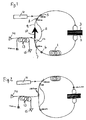
- the Raman laser of figure 1 comprises a fibre loop cavity formed predominantly by a length of Ge-doped silica fibre 1, which is Raman-active with a shift of 434 cm -1 (or in frequency terms, 13THz).
- a selective reflector in the form of a Fabry-Perot etalon 2 designed to have a free spectral range of 434 cm -1 and one of its transmission maxima at 1062 nm. It is thus transparent at the pump wavelength and at many of the Raman wavelengths of the system, including at least the first 5 Raman wavelengths, but has transmission minima between each adjacent pair of these wavelengths to prevent (or at least minimise) any possible laser action at undesirable wavelengths.
- a filter 3 that is transparent at wavelengths in the approximate range from 1062 to 1400 nm, but absorbs radiation with longer wavelengths, which will mainly be Raman radiation of the 6th order or higher.
- a source laser 4 for instance a Yb-doped double-clad fibre laser
- a 1062 nm wavelength-division multiplexor 5 is efficiently coupled into the loop using a 1062 nm wavelength-division multiplexor 5.
- this is of the micro-optic filter type, with three arms only, and in this case a Bragg grating 6 tuned to that wavelength is preferably provided in the main fibre loop to reflect pump radiation and so improve its utilisation.
- a 4-arm multiplexor with a 1062 nm reflecting Bragg grating on its fourth arm.
- the loop is split and recombined by a pair of wavelength-division multiplexor/demultiplexors 7 and 8 so that radiation of the 5th Raman order, that is at 1380 nm, is directed to the bypass route 9 in which an optical isolator 10 allows radiation to pass only in the clockwise direction, while all other relevant wavelengths (that is at least the pump radiation and the first to fourth Raman orders) are directed to the main route 11 in which they pass freely in either direction.
- Laser light output is taken from a power splitter 12, preferably located, as shown, on the route 8 where only the output wavelength is present at any substantial level.
- the output of the laser is shown as being used to pump a counter-propagating Raman fibre laser 13 which receives an optical signal from source 14 and outputs it in amplified form to receiving apparatus 15.
- the alternative form of the invention shown in figure 2 is essentially the same, except that the output laser radiation is taken from the loop in a direction counter to the pump direction by a 1380 nm multiplexor 16 having in its fourth arm a Bragg grating 17 tuned to that wavelength, which receives output-wavelength radiation that may be propagating in the anticlockwise direction and returns it in a clockwise direction from which it is able to reach the output.
- the isolator (10, Figure 1) is thus made unnecessary.
- the doped fibre 1 is re-positioned so that gain still occurs as close as practicable to the output of the laser.
Landscapes
- Physics & Mathematics (AREA)
- Electromagnetism (AREA)
- Engineering & Computer Science (AREA)
- Plasma & Fusion (AREA)
- Optics & Photonics (AREA)
- Lasers (AREA)
- Optical Modulation, Optical Deflection, Nonlinear Optics, Optical Demodulation, Optical Logic Elements (AREA)
Abstract
Description
- This invention relates to lasers and optical amplifiers and to methods of obtaining laser light and amplifying optical signals, primarily in the fields of optical communications and optical data processing.
- Raman amplifiers have a number of attractive features for use in these fields, in particular that they can have high gain over a broad frequency band, but this depends on providing adequate pump energy at the appropriate wavelength. In particular, if they are to be compatible with the "span" lengths of existing fibre optic telecommunication systems, a pump power of at least 1W is needed. This is just about achievable by a semiconductor diode laser in the laboratory, but is a long way from commercial practice, and the best practical option at present available is to multiplex in various ways the output from a number of separate semiconductor laser diodes.
- It has been recognised that Raman amplifiers are potentially capable of much higher power output than diode lasers, but this is not easily achieved with convenient active materials at the frequencies of interest for communications applications, in particular. For example, an amplifier for the S-band of the infra-red optical communications spectrum requires a pump wavelength of about 1380 to 1400 nm, and if this is to be derived from a 1062 nm Yb-doped double-clad fibre laser using Ge-doped silica Raman gain fibre, then five successive Raman shifts of 434 cm-1 (13 THz) each are required, so that the Raman laser must be active at five different wavelengths. In principle, this could be achieved using five pairs of fibre Bragg gratings to define the lasing wavelengths, but such a construction may have poor energy efficiency because of unwanted reflections. In addition, it has been shown that UV exposure used to write gratings can induce a small transmission loss, and this can significantly reduce the efficiency of a laser in which light has to pass through many gratings.
- Nielsen et al have described in IEEE Photonics Technology Letters vol 10 no.10, October 1998 a partial solution to this problem using a circular Raman laser/Raman amplifier topology, but this still requires three in-cavity Bragg gratings in an embodiment for use in the band around 1300 nm; we estimate that extension of this technique to the "S" band around 1500 nm would require at least two and probably three pairs of additional gratings to define additional lasing wavelengths.
- In accordance with one aspect of the invention, a Raman laser comprises a laser cavity containing Raman-active medium, an optical pump coupled to the laser cavity, and means for promoting lasing at plural wavelengths (hereinafter called the "Raman wavelengths") corresponding to the first and successive Raman shifts in the said medium and is characterised in that the said means is a single wavelength-selective element in the cavity and selects at least four periodically related wavelengths, being the first four Raman wavelengths.
- For operation in the S band using a typical germano-silicate Raman-active fibre, we expect that five such wavelengths will need to be selected.
- It is possible to use a linear laser cavity, either with a wavelength-selective reflector that reflects at the Raman wavelengths defining at least one of the cavity ends or with a wavelength-selective transmission element that is transparent at the Raman wavelengths between reflectors defining the cavity ends. We much prefer, however, to use a cavity with ring topology with a selective transmission element that is transparent at the Raman wavelengths, and preferably also at the pump wavelength.
- Preferably the wavelength-selective element is a Fabry-Perot etalon with a free spectral range corresponding to the Raman shift of the medium. The design of such etalons, typically by precision multi-coating, to achieve desired transmission (or reflection) wavelengths and free spectral range is well understood and does not need to be detailed in this application.
- Preferably the laser includes a filter to absorb wavelengths corresponding to Raman orders beyond that of the desired output wavelength, in order that they shall not give rise to interactions that may consume pump energy; or alternatively an angled wavelength-selective reflector might be used to remove such undesired wavelengths from the cavity.
- In the preferred ring topology, laser radiation will unless prevented propagate in both directions. This is not a problem at the intermediate Raman wavelengths, but is inconvenient at the output wavelength, unless dual outputs are desired (say to pump two amplifiers simultaneously or to pump a fibre amplifier from both of its ends). Preferably bi-directional propagation is prevented by using a wavelength-division multiplexor/demultiplexor pair to separate radiation at the output frequency into a bypass route and including in that route an optical isolator so that the bypass route is accessible in one direction only. Alternatively, a wavelength-division multiplexor coupler and reflector may be used to intercept and reverse radiation at the output wavelength that is propagating in the direction away from the desired output.
- The invention also provides an optical amplifier comprising an optical cavity containing an optically active species capable of population inversion, an optical pump for producing population inversion in that species, and means for passing an optical signal through the optical cavity, characterised in that the pump is a laser in accordance with the invention.
- Preferably the active species is Raman-active.
- Preferably the cavity is a fibre cavity, and in such case, the amplifier may also function as a transmission fibre.
The invention also includes a method of obtaining laser light which comprises providing a laser cavity containing Raman-active medium and an optical pump coupled to the laser cavity, and promoting lasing at plural Raman-shifted wavelengths by inserting in the cavity a wavelength-selective element that selects at least four periodically-related wavelengths, being the first four Raman wavelengths. - The invention further includes a method of amplifying an optical signal comprising passing the signal through a cavity containing an optically active material capable of population inversion, and obtaining such population inversion by pumping with laser radiation obtained by the method of the invention.
- The invention will be further described, by way of example, with reference to the accompanying drawings in which each of Figures 1 and 2 is a diagrammatic representation of one form of laser-amplifier in accordance with the invention.
- The Raman laser of figure 1 comprises a fibre loop cavity formed predominantly by a length of Ge-doped silica fibre 1, which is Raman-active with a shift of 434 cm-1 (or in frequency terms, 13THz). Into the loop is inserted a selective reflector in the form of a Fabry-Perot etalon 2 designed to have a free spectral range of 434 cm-1 and one of its transmission maxima at 1062 nm. It is thus transparent at the pump wavelength and at many of the Raman wavelengths of the system, including at least the first 5 Raman wavelengths, but has transmission minima between each adjacent pair of these wavelengths to prevent (or at least minimise) any possible laser action at undesirable wavelengths.
- Also inserted in the loop is a
filter 3 that is transparent at wavelengths in the approximate range from 1062 to 1400 nm, but absorbs radiation with longer wavelengths, which will mainly be Raman radiation of the 6th order or higher. - Pump radiation at 1062 nm from a source laser 4 (for instance a Yb-doped double-clad fibre laser) is efficiently coupled into the loop using a 1062 nm wavelength-
division multiplexor 5. As shown, this is of the micro-optic filter type, with three arms only, and in this case a Bragg grating 6 tuned to that wavelength is preferably provided in the main fibre loop to reflect pump radiation and so improve its utilisation. Alternatively, it is possible to use a 4-arm multiplexor with a 1062 nm reflecting Bragg grating on its fourth arm. - The loop is split and recombined by a pair of wavelength-division multiplexor/
demultiplexors 7 and 8 so that radiation of the 5th Raman order, that is at 1380 nm, is directed to thebypass route 9 in which an optical isolator 10 allows radiation to pass only in the clockwise direction, while all other relevant wavelengths (that is at least the pump radiation and the first to fourth Raman orders) are directed to the main route 11 in which they pass freely in either direction. - Laser light output is taken from a power splitter 12, preferably located, as shown, on the
route 8 where only the output wavelength is present at any substantial level. - For the purpose of illustration, the output of the laser is shown as being used to pump a counter-propagating
Raman fibre laser 13 which receives an optical signal fromsource 14 and outputs it in amplified form to receivingapparatus 15. - The alternative form of the invention shown in figure 2 is essentially the same, except that the output laser radiation is taken from the loop in a direction counter to the pump direction by a 1380 nm multiplexor 16 having in its fourth arm a Bragg grating 17 tuned to that wavelength, which receives output-wavelength radiation that may be propagating in the anticlockwise direction and returns it in a clockwise direction from which it is able to reach the output. The isolator (10, Figure 1) is thus made unnecessary. The doped fibre 1 is re-positioned so that gain still occurs as close as practicable to the output of the laser.
- Any discussion of the background to the invention herein is included to explain the context of the invention. Where any document or information is referred to as "known", it is admitted only that it was known to at least one member of the public somewhere prior to the date of this application. Unless the content of the reference otherwise clearly indicates, no admission is made that such knowledge was available to the public or to experts in the art to which the invention relates in any particular country (whether a member-state of the PCT or not), nor that it was known or disclosed before the invention was made or prior to any claimed date. Further, no admission is made that any document or information forms part of the common general knowledge of the art either on a world-wide basis or in any country and it is not believed that any of it does so, with the exception of the design and manufacture of etalons.
Claims (28)
- A Raman laser comprising a laser cavity containing Raman-active medium, an optical pump coupled to the laser cavity, and means for promoting lasing at plural wavelengths ("the Raman wavelengths") corresponding to the first and successive Raman shifts in the said medium characterised in that the said means is a single wavelength-selective element in the cavity and selects at least four periodically-related wavelengths, being the first four Raman wavelengths.
- A Raman laser as claimed in claim 1 in which the said cavity has a ring topology and the selective element is a selective transmission element that is transparent at the Raman wavelengths.
- A Raman laser as claimed in claim 1 or claim 2 in which the selective transmission element is transparent at the first five Raman wavelengths and at the pump wavelength.
- A Raman laser as claimed in any one of claims 1-3 comprising a wavelength-division multiplexor/demultiplexor pair effective to separate radiation at output frequency into a bypass route and including in that route an optical isolator so that the bypass route is accessible in one direction only.
- A Raman laser as claimed in any one of claims 1-3 in which a wavelength-division multiplexor coupler and reflector is set to intercept and reverse radiation at the output wavelength that is propagating in the direction away from the desired output.
- A Raman laser as claimed in any one of claims 1-5 in which the wavelength-selective reflector is a Fabry-Perot etalon with a free spectral range corresponding to the Raman shift of the medium.
- A Raman laser as claimed in any one of claims 1-6 including a filter to absorb wavelengths corresponding to Raman orders beyond that of the desired output wavelength.
- An optical amplifier comprising an optical cavity containing an optically active species capable of population inversion, an optical pump for producing population inversion in that species, and means for passing an optical signal through the optical cavity, characterised in that the pump is a laser in accordance with any one of claims 1-7.
- An optical amplifier as claimed in claim 8 in which the active species is Raman-active.
- An optical amplifier as claimed in claim 9 in which the cavity is a fibre cavity and the amplifier also functions as a transmission fibre.
- A method of obtaining laser light which comprises providing a laser cavity containing Raman-active medium and an optical pump coupled to the laser cavity, and promoting lasing at plural Raman-shifted wavelengths by inserting in the cavity a wavelength-selective element that selects at least four periodically-related wavelengths, being the first four Raman wavelengths.
- A method as claimed in claim 11 in which the said cavity has a ring topology and the selective element is a selective transmission element that is transparent at the Raman-shifted wavelengths.
- A method as claimed in claim 11 or claim 12 comprising using a selective transmission element that is transparent at the first five Raman wavelengths and at the pump wavelength.
- A method as claimed in any one of claims 11-13 comprising using a wavelength-division multiplexor/demultiplexor pair to separate radiation at output frequency into a bypass route and including in that route an optical isolator so that said radiation may traverse the bypass route in one direction only.
- A method as claimed in any one of claims 11-14 comprising using a wavelength-division multiplexor coupler and reflector to intercept and reverse radiation at the output wavelength that is propagating in the direction away from the desired output.
- A method as claimed in any one of claims 11-15 comprising using as the wavelength-selective element a Fabry-Perot etalon with a free spectral range corresponding to the Raman shift of the medium.
- A method as claimed in any one of claims 11-16 comprising including a filter to absorb wavelengths corresponding to Raman orders beyond that of the desired output wavelength.
- A method of amplifying an optical signal comprising passing the signal through a cavity containing an optically active material capable of population inversion, and obtaining such population inversion by pumping with laser radiation obtained by the method claimed in any one of claims 11-17.
- A method as claimed in claim 118 comprising using as the said optically active material one that is Raman-active.
- An method as claimed in claim 19 in which the cavity is a fibre cavity comprising using the amplifier also as a transmission fibre.
- A laser substantially as described with reference to Figure 1.
- A laser substantially as described with reference to Figure 2.
- An optical amplifier substantially as described with reference to Figure 1.
- An optical amplifier substantially as described with reference to Figure 2.
- A method of generating laser radiation substantially as described with reference to Figure 1.
- A method of generating laser radiation substantially as described with reference to Figure 2.
- A method of amplifying an optical signal substantially as described with reference to Figure 1.
- A method of amplifying an optical signal substantially as described with reference to Figure 2.
Priority Applications (1)
| Application Number | Priority Date | Filing Date | Title |
|---|---|---|---|
| EP02290172A EP1331708A1 (en) | 2002-01-24 | 2002-01-24 | Laser, optical amplifiers, and methods of obtaining laser light and amplifying optical signals |
Applications Claiming Priority (1)
| Application Number | Priority Date | Filing Date | Title |
|---|---|---|---|
| EP02290172A EP1331708A1 (en) | 2002-01-24 | 2002-01-24 | Laser, optical amplifiers, and methods of obtaining laser light and amplifying optical signals |
Publications (1)
| Publication Number | Publication Date |
|---|---|
| EP1331708A1 true EP1331708A1 (en) | 2003-07-30 |
Family
ID=8185707
Family Applications (1)
| Application Number | Title | Priority Date | Filing Date |
|---|---|---|---|
| EP02290172A Withdrawn EP1331708A1 (en) | 2002-01-24 | 2002-01-24 | Laser, optical amplifiers, and methods of obtaining laser light and amplifying optical signals |
Country Status (1)
| Country | Link |
|---|---|
| EP (1) | EP1331708A1 (en) |
Cited By (1)
| Publication number | Priority date | Publication date | Assignee | Title |
|---|---|---|---|---|
| WO2006032110A1 (en) * | 2004-09-23 | 2006-03-30 | Macquarie University | A selectable multiwavelength laser |
Citations (2)
| Publication number | Priority date | Publication date | Assignee | Title |
|---|---|---|---|---|
| US6052393A (en) * | 1996-12-23 | 2000-04-18 | The Regents Of The University Of Michigan | Broadband Sagnac Raman amplifiers and cascade lasers |
| WO2001054238A1 (en) * | 2000-01-24 | 2001-07-26 | Sdl, Inc. | Cascaded raman resonator with sampled grating structure |
-
2002
- 2002-01-24 EP EP02290172A patent/EP1331708A1/en not_active Withdrawn
Patent Citations (2)
| Publication number | Priority date | Publication date | Assignee | Title |
|---|---|---|---|---|
| US6052393A (en) * | 1996-12-23 | 2000-04-18 | The Regents Of The University Of Michigan | Broadband Sagnac Raman amplifiers and cascade lasers |
| WO2001054238A1 (en) * | 2000-01-24 | 2001-07-26 | Sdl, Inc. | Cascaded raman resonator with sampled grating structure |
Non-Patent Citations (3)
| Title |
|---|
| CHANG D I ET AL: "Efficient cascaded Raman generation and signal amplification at 1.3 mum in GeO2-doped single-mode fibre", OPTICS COMMUNICATIONS, NORTH-HOLLAND PUBLISHING CO. AMSTERDAM, NL, vol. 142, no. 4-6, 15 October 1997 (1997-10-15), pages 289 - 293, XP004093999, ISSN: 0030-4018 * |
| KOCH F ET AL: "CW, multiple wavelength, room temperature, Raman fiber ring laser with external 19 channel, 10GHz pulse generation in a single electro-absorption modulator", OFC 2001. OPTICAL FIBER COMMUNICATION CONFERENCE AND EXHIBIT. TECHNICAL DIGEST POSTCONFERENCE EDITION (IEEE CAT. 01CH37171), OFC 2001. OPTICAL FIBER COMMUNICATION CONFERENCE AND EXHIBITION. TECHNICAL DIGEST, ANAHEIM, CA, USA, 17-22 MARCH 2001, 2001, Washington, DC, USA, Opt. Soc. America, USA, pages WDD7 - 1-3 vol.3, XP002213396, ISBN: 1-55752-655-9 * |
| NIELSEN T N ET AL: "8 X 10 GB7S 1.3-MUM UNREPEATERED TRANSMISSION OVER A DISTANCE OF 141 KM WITH RAMAN POST - AND PRE-AMPLIFIERS", IEEE PHOTONICS TECHNOLOGY LETTERS, IEEE INC. NEW YORK, US, vol. 10, no. 10, 1 October 1998 (1998-10-01), pages 1492 - 1494, XP000786689, ISSN: 1041-1135 * |
Cited By (1)
| Publication number | Priority date | Publication date | Assignee | Title |
|---|---|---|---|---|
| WO2006032110A1 (en) * | 2004-09-23 | 2006-03-30 | Macquarie University | A selectable multiwavelength laser |
Similar Documents
| Publication | Publication Date | Title |
|---|---|---|
| US6195200B1 (en) | High power multiwavelength light source | |
| US6529314B1 (en) | Method and apparatus using four wave mixing for optical wavelength conversion | |
| EP0938172B1 (en) | Apparatus comprising an improved cascaded optical fiber raman device | |
| US6625180B2 (en) | Raman fiber laser | |
| US6374006B1 (en) | Chirped period gratings for raman amplification in circulator loop cavities | |
| US5572357A (en) | Optical system for amplifying signal light | |
| EP0984532B1 (en) | Article comprising an optical fiber cascaded Raman resonator | |
| US5991070A (en) | Optical amplifier with oscillating pump energy | |
| US6567430B1 (en) | Raman oscillator including an intracavity filter and amplifiers utilizing same | |
| JPH09232661A (en) | Optical system and device using natural luminescence evenly amplified in spectrum | |
| JP2000232248A (en) | Multi-wavelength exciting light multiplexing device, and multi-wavelength exciting light source and optical amplifier incooperating the device | |
| EP1318579A1 (en) | Multi-wavelength raman laser | |
| US7463411B2 (en) | Optical fiber amplifier | |
| JP2002006348A (en) | Optical amplifier | |
| US6721088B2 (en) | Single-source multiple-order raman amplifier for optical transmission systems | |
| KR100622015B1 (en) | Amplified spontaneous emission reflector-based gain-clamped fiber amplifier | |
| KR100438426B1 (en) | Unpolarized multi lambda source | |
| JPH053356A (en) | Optical fiber amplifier | |
| EP1331708A1 (en) | Laser, optical amplifiers, and methods of obtaining laser light and amplifying optical signals | |
| US7095554B2 (en) | Pumping method and unit for optical amplifiers | |
| EP0964486A2 (en) | Optical fiber amplifier | |
| WO2002093697A2 (en) | Fiber laser having a suppressor | |
| EP0939465A2 (en) | Light-source with WDM function, and optical amplifier and two-way optical transmission applied therewith | |
| JP2000031573A (en) | Optical amplifier | |
| RU2152676C1 (en) | Fiber laser (design versions) |
Legal Events
| Date | Code | Title | Description |
|---|---|---|---|
| PUAI | Public reference made under article 153(3) epc to a published international application that has entered the european phase |
Free format text: ORIGINAL CODE: 0009012 |
|
| AK | Designated contracting states |
Designated state(s): AT BE CH CY DE DK ES FI FR GB GR IE IT LI LU MC NL PT SE TR |
|
| AX | Request for extension of the european patent |
Extension state: AL LT LV MK RO SI |
|
| 17P | Request for examination filed |
Effective date: 20031217 |
|
| AKX | Designation fees paid |
Designated state(s): FR GB |
|
| 17Q | First examination report despatched |
Effective date: 20040316 |
|
| REG | Reference to a national code |
Ref country code: DE Ref legal event code: 8566 |
|
| STAA | Information on the status of an ep patent application or granted ep patent |
Free format text: STATUS: THE APPLICATION IS DEEMED TO BE WITHDRAWN |
|
| 18D | Application deemed to be withdrawn |
Effective date: 20050419 |