EP1331686A2 - Waveguide adaptor assembly and method - Google Patents
Waveguide adaptor assembly and method Download PDFInfo
- Publication number
- EP1331686A2 EP1331686A2 EP03000604A EP03000604A EP1331686A2 EP 1331686 A2 EP1331686 A2 EP 1331686A2 EP 03000604 A EP03000604 A EP 03000604A EP 03000604 A EP03000604 A EP 03000604A EP 1331686 A2 EP1331686 A2 EP 1331686A2
- Authority
- EP
- European Patent Office
- Prior art keywords
- waveguide
- flange
- adaptor
- flanges
- interface
- Prior art date
- Legal status (The legal status is an assumption and is not a legal conclusion. Google has not performed a legal analysis and makes no representation as to the accuracy of the status listed.)
- Granted
Links
Images




Classifications
-
- H—ELECTRICITY
- H01—ELECTRIC ELEMENTS
- H01P—WAVEGUIDES; RESONATORS, LINES, OR OTHER DEVICES OF THE WAVEGUIDE TYPE
- H01P1/00—Auxiliary devices
- H01P1/04—Fixed joints
- H01P1/042—Hollow waveguide joints
-
- Y—GENERAL TAGGING OF NEW TECHNOLOGICAL DEVELOPMENTS; GENERAL TAGGING OF CROSS-SECTIONAL TECHNOLOGIES SPANNING OVER SEVERAL SECTIONS OF THE IPC; TECHNICAL SUBJECTS COVERED BY FORMER USPC CROSS-REFERENCE ART COLLECTIONS [XRACs] AND DIGESTS
- Y10—TECHNICAL SUBJECTS COVERED BY FORMER USPC
- Y10T—TECHNICAL SUBJECTS COVERED BY FORMER US CLASSIFICATION
- Y10T29/00—Metal working
- Y10T29/49—Method of mechanical manufacture
- Y10T29/49002—Electrical device making
- Y10T29/49016—Antenna or wave energy "plumbing" making
Definitions
- the present invention relates generally to waveguides, and more particularly, but not by way of limitation, to a method of and apparatus for coupling a waveguide flange assembly to a waveguide.
- Waveguides are commonly used for transmitting electromagnetic wave energy from one point to another.
- One of the more extensive commercial uses of waveguides is the transmission of electromagnetic signals from transmitting or receiving equipment. This transmission may occur, for example, between an equipment shelter and an antenna, often mounted on a tall tower.
- the waveguide consists of a hollow metallic tube of defined cross-section, uniform in extent in the direction of propagation. Within the hollow tube, the electric and magnetic fields are confined, and, since the tubes are normally filled with air, dielectric losses are minimal.
- Commercially available waveguides may be either of the rigid wall or flexible variety and their cross sectional shapes may be rectangular, circular and elliptical. Such waveguide shapes are, for example, disclosed in U.S. Patent Nos. 3,822,411 to Merle and 4,047,133 to Merle.
- waveguides It is generally necessary for waveguides to be coupled to transmitting or receiving equipment at some point. Both the design of the waveguide, as well as coupling systems for use therewith, are critical to the efficiency of the overall system and thus certain design parameters must be applied. For example, it is well known to preclude the generation of field variations with height and their attendant unwanted modes. It is similarly well-known to securely mount a waveguide within a waveguide flange connector in order to prevent reflection losses and impendence mismatches. Reliable and secure mountings are not, however, always easy to accomplish. It is for this reason that waveguide flange and coupling assemblies have been designed and implemented for connecting waveguides one to the other as well as to receiving or transmitting equipment.
- the waveguide flange and coupling assembly Due to the variety of applications and variations in the design of such transmitting and receiving equipment as well as variations in the designs of waveguides, the waveguide flange and coupling assembly has become an area of intense design focus. Not the least of the reasons for the above referenced focus is the functional efficiency of the waveguide flange and coupling assembly. It is well known that trouble may occur either between the waveguide and its flange or between the two mating flanges of coupled waveguides as well as between a waveguide and equipment being connected thereto. Possible problems which may be encountered include reflected power, high vswr (voltage standing wave ratio), power leakage and arcing. It is thus critical to provide the appropriate coupling mechanism and methods of assembly for use therewith when linking waveguides to one another or to transmitting or receiving equipment.
- Waveguide connectors including flange and coupling assemblies exemplifying prior designs are set forth and disclosed in U.S. Patent No. 3,374,450 to Stewart (the '450 patent) as well as U.S. Patent No. 3,500,264 to Floyd (the '264 patent).
- the 450 patent discloses a waveguide flange and coupling assembly and outlines various aspects of waveguide connection construction. A plurality of clamping elements including a collar and flange member permit waveguide sections to be more easily assembled one to the other and both rigid and flexible waveguides are addressed.
- the '264 patent entitled “Connections Means For Waveguide Means” also discloses a method of and apparatus for connecting together sections of waveguides without soldering.
- 3,821,670 assigned to Hughes Aircraft Company discloses a "universal type of waveguide flange" aligning and quick release assembly for coupling and decoupling abutting waveguide flanges.
- the above-referenced functional efficiency and substantially loss free connection aspects are similarly addressed in this reference.
- Waveguide and waveguide flange coupling assemblies are critical to the telecommunication industry and necessitate similar production planning and inventory considerations relating to that of other telecommunications equipment. Parts must be kept in stock for particular applications despite the frequency of use. In a competitive economic environment it is, however, incumbent upon manufacturers and suppliers of equipment such as waveguides and waveguides flange adaptors for the telecommunication industry to be able to provide the requisite parts in a relatively short period of time.
- One approach to reducing inventory capital is to manufacture fewer parts having unique applications.
- the present invention provides such an approach by utilizing a waveguide flange adaptor capable of multiple applications.
- waveguide flange adaptor for the mounting of a plurality of waveguide flanges thereto and semi-permanently affixed to at least one end of a waveguide can reduce the required inventory of waveguide assemblies.
- the use of waveguides is prolific in the telecommunication industry, where specifications for standard flange interfaces, including waveguide mounting flanges, vary from one application to another. There are multiple reasons for such design variations. Flange interface standards vary in different regions of the world, and the designs of one manufacturer may require mating styles and configurations that are different from those of other manufacturers.
- the waveguides themselves are typically of standard dimensions, while a waveguide flange for coupling a standard waveguide to one transmitter may not be adapted for coupling to a flange interfaces of another manufacturer's equipment. For that reason, waveguide sections must be produced with a variety of mounting flanges, typically permanently secured on the ends thereof.
- One of the preferred methods of mounting a waveguide to a waveguide flange incorporates the use of molten solder. Although various disadvantages may exist in the use of solder, it is well known that reliable mounting configurations maybe affected with solder for maintaining the integrity of the flange interface with that of the waveguide and reducing inefficiencies associated therewith.
- the present invention provides such a system by providing a waveguide assembled with a flange adaptor on one or both ends thereof.
- the flange adaptor is designed for interfacing with a plurality of waveguide mounting flanges.
- a single waveguide and flange adaptor can be utilized for a variety of waveguide flanges and related applications, while minimizing the requisite inventory issues. Also, if a customer is using the present invention and attempting to mount a waveguide to a radio, antenna, waveguide, or other standard flange interface, and that customer has ordered the wrong flange type, the supplier can simply rush the customer a number of the correct flange types so that field installation will not have to be deferred.
- FIG. A a prior art waveguide mounting assembly is shown where a flange is soldered to a rectangular waveguide in order to facilitate connection to a radio, antenna, or another waveguide.
- the flange abuts a flange interface which is affixed to the radio, antenna, or other waveguide.
- To facilitate connection between the flange and the flange interface one might use screws, bolts, rivets, solder, etc.
- the disadvantage of the assembly pictured in FIG. A lies in the fact that, as explained above, there are a variety of flange interfaces used in the industry and this assembly does not accommodate such a variety.
- the present invention alleviates such a problem by simply having a waveguide adaptor assembly for connecting a waveguide to a standard flange interface on a radio, antenna or another section of waveguide. Rather than semi-permanently (as by soldering) attaching the waveguide directly to a flange, and then having to inventory all those combinations, the soldering is done on a flange adaptor which can be mated with a variety of flanges that are compatible with any of the various standard flange interfaces for a given waveguide size or cross-sectional geometry. The invention thus drastically reduces the inventorying problem.
- FIG. 1 there is shown a waveguide 10 to which is mounted to a flange adaptor 12 on a first end 14 of the waveguide into the waveguide side of the flange adaptor 12.
- a flange adaptor 12 Opposite the waveguide side of the flange adaptor 12 is the opposed flange side having a predetermined flange coupling interface for mating against a flange.
- the waveguide 10 is of the generally rectangular variety and, in this embodiment, is of rigid construction.
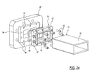
- FIG. 1A illustrates a reverse perspective view of the waveguide-flange adaptor assembly of FIG. 1 connected to a flange 20.
- end 14 fits into a waveguide mounting region 70 on the waveguide side of the flange adaptor 12.
- threaded screws 42 are screwed into the adaptor side of the flange 20 to secure abutment between the adaptor side of flange 20 and the flange side of the flange adaptor 12. This will be discussed in more detail below.
- fastening means may be used in place of threaded screws 42, such as rivets, bolts, welds, solder, etc.
- apertures 40 through flange 20 allow for fastening means such as bolts, screws, rivets, etc. to be placed therethrough.
- the geometry of the flange interface side of flange 20 is varied depending on the geometry of the flange interface (not shown) for which the waveguide adaptor assembly is to be connected.
- the adaptor side of flange 20 must always be compatible with the flange side of flange adaptor 12.
- the first flange adaptor 12 of first end 14 is shown in an exploded view relative to waveguide 10 for purposes of illustrating the attachment of a waveguide flange thereto.
- a waveguide flange 20 is shown with the appropriate hardware in accordance with the principles of the present invention.
- the waveguide flange 20 comprises one of a variety of waveguide flanges that may be utilized with the flange adaptor 12.
- Other waveguide flanges will be described in more detail below, and it should be noted that the particular mounting method and apparatus as set forth in FIG. 2 may likewise be utilized relative to said flanges described in more detail below.
- the flange adaptor 12 in order to secure the waveguide 10 to the flange adaptor 12, the flange adaptor 12 is adapted for receiving end 14 of waveguide 10 within a waveguide mounting region 70 of the waveguide side of the flange adaptor 12. To provide for secure engagement, end 14 is typically soldered in place within the waveguide mounting region 70. In order to secure the flange adaptor 12 to the flange 20, apertures 47 are formed through the flange adaptor 12 to allow for receipt of threaded screws 42. When the components of FIGs.
- the threaded screws 42 go through apertures 47 and into corresponding apertures 72 of flange 20 to secure the flange interface side of flange 20 to the flange side 73 of flange adaptor 12.
- Apertures 72 of flange 20 are not bored completely through flange 20, but only bored with enough depth to allow threaded screws 42 to securely engage the flange adaptor 12 to the flange interface side of flange 20.
- a groove 71 may be formed in the flange side 73 of flange adaptor 12. This is necessary to block the ingress of moisture and because the waveguide assemblies of the present invention may be pressurized.
- the waveguide flange 20 is designed for mating with another flange (not shown) or the mating surface of equipment (not shown).
- a plurality of apertures 40 are formed in waveguide flange 20, the apertures 40 being adapted to receive coupling members therethrough.
- securing hardware such as threaded nuts (not shown) would be provided in association with threaded bolts (not shown).
- the bolts are preferably pre-installed within the apertures 40 of the waveguide flange 20 when said flange is initially mounted to the flange adaptor 12.
- the purpose of this initial assembly is to provide the waveguide flange 20 with the necessary hardware for coupling to a mating flange or mating surface.
- the bolts would not necessarily be installed within the apertures 40 of waveguide flange 20.
- FIGS. 3 and 3A there is shown an enlarged perspective view and a reversed enlarged perspective view, respectively, of the flange adaptor 12 (as seen in FIGS 1-2) for use with the rigid waveguide 10.
- the present invention may also be used with a flexible waveguide with slight modifications to the flange adaptor.
- FIG. 4 there is an exploded perspective view of the flange/waveguide assembly using a flexible waveguide 10A.
- a jacket 18 is typically provided around the waveguide 10A, however, in order to allow assembly to the flange adaptor 12A, the jacket 18 leaves the front end 14A of the waveguide 10A bare.
- a rear flange 24 is provide on flange adaptor 12A which adheres to the jacket 18.
- the adhesion of the jacket 18 to the waveguide 10 and flange adaptor 12 is preferably facilitated by the application of heat.
- the jacket 18 may be made of neoprene or the like, which will bond to metal surfaces when heated.
- the flange adaptor 12A has an elongated region 25. This allows the threaded screws 42A of the present embodiment to be placed into the apertures 47A without impediment from the rear flange 24.
- the geometries and functions of the front end 73A of the flange adaptor 12A, the gasket 80A, and the flange 20A are identical to those describe in relation to the rigid waveguide assembly in FIGS. 1-2, and will not be repeated herein.
- FIGS. 5 and 5A there is shown an enlarged perspective view and a reversed enlarged perspective view, respectively, of the flange adaptor 12A (as seen in FIG. 4) for use with the flexible waveguide 10A.
- the flange adaptor 12A of this particular embodiment has a generally rectangular passageway formed therethrough.
- waveguide mounting flanges having variations in shape and size will be specifically set forth and shown. Other shapes and sizes are considered to be within the spirit and scope of the present invention.
- the flange adaptor 12A is provided with a waveguide mounting region 70A comprising a shoulder 58 to abut the end 14A of the waveguide 10A (seen in FIG. 4).
- the waveguide 10A of the present embodiment is typically soldered to the flange adaptor 12A when end 14A is properly disposed in waveguide mounting region 70A abutting shoulder 58.
- the flange adaptor 12A is preferably formed of stainless steel, or the like, and may be milled from bar stock or initially cast and milled therefrom. Such manufacturing techniques are well known in the industry. Likewise, it is well known to connect a waveguide 10A of the type shown in FIGS. 4 and 4A to waveguide flanges with the use of solder or the like. It is for this reason that the shoulder 58 is of sufficient length for receiving the requisite portion of the waveguide 10A as shown in FIG. 4 for the application of solder thereto. In order for the jacket 18 to have sufficient bonding area, the rear flange 24 must be of sufficient height.
- the elongated region 25 must be of sufficient length.
- the flange adaptor 12A of the present embodiment has apertures 47A to facilitate threaded screws or another type securing mechanism, and a groove 71A to allow for a gasket to allow air-tight joining to a flange.
- FIGS. 2-2A and 4 There are a number of standard mating flanges presently in the field.
- the present invention allows the waveguide/flange adaptor assemblies of FIGS. 2-2A and 4 to be connected to any of these standard mating flanges just by altering the geometry of flange 20 and 20A seen in FIGS. 2-2A and 4.
- a rear portion of the flange should be raised (as with flange interface side of flange 20 in FIG. 2A) and have partially drilled apertures therethrough (as with apertures 72 in flange interface side of flange 20 in FIG. 2A) that line up with apertures 47 and 47A of the flange adaptors 12 and 12A (FIGS.
- FIGS 6A-8D illustrate a variety of geometries of flanges that may be used with the present invention to enable compatibility with other mating surfaces in the field. It should be understood that the rear faces of each of these flanges have raised rear portions 76 (seen in FIG. 6B) with partially drilled apertures 75 (seen in FIG. 6B) that line up with apertures 47 and 47A of the flange adaptors 12 and 12A.
- Waveguide flange 100 is formed of a generally rectangular body which includes a plurality of holes 104 formed therethrough and adapted for coupling to a mating surface.
- a generally rectangular passage 106 is formed centrally through the waveguide body 102 and is further circumscribed by a recess 108 formed therearound.
- the recess 108 is preferably formed for the receipt of a gasket to be utilized in the mounting of waveguide flange 100 to a mating surface.
- FIG. 6B there is shown a perspective view of the rear surface of the waveguide flange 100 illustrating certain aspects of the construction thereof.
- a raised rear portion 76 is provided with threaded holes 75 partially drilled therethrough for securely receiving threaded screws 42 seen in FIGS. 2-2A and 4.
- the spacing of plurality of holes 104 is selected relative to the hole patterns of the mating surface.
- FIG. 7A through 7D there are shown four different rectangular waveguide flange designs.
- a rectangular waveguide flange 120 is formed with apertures 122 comprising a hole pattern 123.
- the face 124 of waveguide flange 120 includes a recess 126 which is formed around a central passageway 125.
- the recess 126 may be seen to be found at a greater depth than that shown in FIG. 6A for recess 108.
- FIG. 7B there is shown a rectangular waveguide flange 130 having a plurality of apertures 132 in a hole pattern 134 that is distinctly dissimilar to the hole pattern 123 of flange 120 of FIG. 7A.
- the waveguide flange 130 includes a generally rectangular central passage 136 that is adapted for mating engagement with the flange adaptors 12 and 12A of FIGS. 3-3A and 5-5A as described above.
- the variation in the hole pattern 134 of waveguide flange 130 illustrates the fact that the waveguide flange 130 is adapted for receiving a variety of hole patterns for the securement of mating surfaces thereon.
- waveguide flange 140 is set forth and shown in yet a different configuration relative to the waveguide flanges of FIG. 7A and 7B.
- waveguide flange 140 has a plurality of apertures 142 forming a pattern 144 which appears similar to the pattern 123 of apertures 122 in waveguide flange 120 of FIG. 7A
- the face 146 of waveguide flange 140 is planar. It is not formed with a gasket recess, as was the case with waveguide flange 130 of FIG. 7B.
- FIG. 7D there is shown a waveguide flange 150 having a plurality of holes 152 in a pattern 154.
- a central passageway 156 is found therethrough. It may be seen that the thickness of waveguide flange 150 is less than that shown for the waveguide flanges in FIGS. 7A-7C.
- Waveguide flange 160 having a distinctly dissimilar shape to that of the waveguide flanges of FIGS. 6A and 6B, and 7A through 7D.
- Waveguide flange 160 presents a circular, or round shape with a rectangular passage 162 formed therethrough.
- the face 164 of round waveguide flange 160 is likewise constructed with round recesses 166 and 167 formed within face 164 thereof.
- the plurality of apertures 169 are formed therein in an aperture array 161. It may be seen that aperture array 161 is circular in shape and will thus require rear face (not shown) having a shape and size accommodating mounting to the flange adaptors 12 and 12A.
- FIG. 8B there is shown yet another round waveguide flange 170 having a generally rectangular passage 172 formed therein.
- the plurality of apertures 173 are formed in a hole pattern 174.
- the face 176 of round waveguide flange 170 is substantially planar in construction.
- FIG. 8C there is shown yet another waveguide flange 180 having a plurality of apertures 182 formed in a hole pattern 184 therearound.
- a generally rectangular passage 186 is formed in the face 188 of the generally round waveguide flange 180.
- a recess 189 is formed in the face 188 and provides a surface for the seating of a gasket therein.
- a generally rectangular waveguide flange 190 is shown formed with a plurality of apertures 192 formed therein in an array 194.
- a generally rectangular passageway 196 is likewise formed therethrough.
- a plurality of the apertures 192 are threaded.
- holes 197 include dotted lines found across the rear surface 198 of waveguide flange 190. As referenced above, some mating surfaces are designed with alternating threaded and clearance holes.
Landscapes
- Waveguide Connection Structure (AREA)
- Mutual Connection Of Rods And Tubes (AREA)
- Flanged Joints, Insulating Joints, And Other Joints (AREA)
Abstract
Description
Claims (16)
- A waveguide adaptor assembly for coupling a waveguide to a radio, antenna, waveguide or other standard flange interface, comprising:an adaptor having a waveguide side adapted to be connected to a waveguide and an opposed flange side having a predetermined flange coupling interface, anda flange having a flange interface side adapted to mate with a particular standard flange interface, and an opposed adaptor side configured to mate with said predetermined flange coupling interface on said adaptor.
- The waveguide adaptor assembly of Claim 1 wherein said flange is selected from a library of flanges adapted for different standard flange interfaces.
- The waveguide adaptor assembly of Claim 2 wherein said flanges in said library of flanges have on said adaptor side a common provision configured to mate with said predetermined flange coupling interface of said adaptor.
- The waveguide adaptor assembly of Claim 3 wherein said provision includes a raised portion.
- The combination comprising:a radio, antenna, waveguide or other structure having a standard flange interface; anda waveguide adaptor assembly for coupling a waveguide to said standard flange interface, comprising:an adaptor having a waveguide side adapted to be connected to a waveguide and an opposed flange side having a predetermined flange coupling interface; anda flange having a flange interface side adapted to mate with a particular standard flange interface, and an opposed adaptor side configured to mate with said predetermined flange coupling interface on said adaptor.
- The combination of Claim 5 wherein said flange is selected from a library of flanges of adapted for different standard flange interfaces.
- The combination of Claim 5 wherein said adaptor has on said flange side a central opening surrounded by a recess adapted to receive a gasket.
- The combination of Claim 6 wherein said flanges in said library of flanges have on said adaptor side a common provision configured to mate with said predetermined flange coupling interface of said adaptor.
- The combination of Claim 8 wherein said provision includes a raised portion.
- A system for coupling one of a plurality of waveguide flanges to a waveguide,
wherein said waveguide flanges have a generally common internal mating configuration, said system comprising:at least one flange adaptor having inner and outer surfaces and wherein said outer surface is adapted to engage said generally common internal mating configuration of said waveguide flanges and said inner surface is adapted for secured mounting to said waveguide;at least one clamping member adapted for fastening to select ones of said waveguide flanges; andat least one fastener for securing said at least one flange adaptor between said at least one clamping member and said select ones of said waveguide flanges such that said waveguide and said at least one flange adaptor mounted thereto may be coupled to select ones of said waveguide flanges for use therewith. - The system as set forth in Claim 10, wherein said waveguide is generally rectangular in cross sectional configuration.
- The system as set forth in Claim 11, wherein said inner surface of said at least one flange adaptor comprises a generally rectangular sleeve adapted for receiving said one of a plurality of waveguide flanges therein, said sleeve having a shoulder formed thereacross for the abutting engagement of an end of said waveguide thereagainst.
- The system as set forth in Claim 10, wherein said inner surface of said at least one flange adaptor comprises a waveguide mounting region adapted for receiving an end of said waveguide therein for the secured mounting thereto.
- A method for coupling one of a plurality of waveguide flanges to a waveguide, wherein said waveguide flanges have a generally common internal mating configuration, said method comprising the steps offorming a flange adaptor having inner and outer surfaces and wherein said outer surface is adapted to engage said generally common internal mating configuration of said waveguide flanges and said inner surface is adapted for secured mounting to a said waveguide; andclamping said at least one of a plurality of waveguide flanges to said outer surface of said flange adaptor such that said waveguide and said flange adaptor mounted thereto may be coupled to said select ones of said waveguide flanges for use therewith.
- The method as set forth in Claim 14, wherein said waveguide is generally rectangular in cross sectional configuration and said step of forming said flange adaptor includes forming said inner surface in a generally rectangular configuration.
- The method as set forth in Claim 15 and further including the step of providing said one of a plurality of waveguide flanges in a generally rectangular configuration adapted for mounting to said generally rectangular waveguide and the step of forming said at least one flange adaptor with a generally rectangular passageway therethrough and axially aligning said passageway with said generally rectangular waveguide for the securement thereto.
Priority Applications (2)
| Application Number | Priority Date | Filing Date | Title |
|---|---|---|---|
| EP08007879A EP1959517A3 (en) | 2002-01-24 | 2003-01-14 | Waveguide adaptor assembly and method |
| EP08016992A EP2001075A1 (en) | 2002-01-24 | 2003-01-14 | Waveguide adaptor assembly mode |
Applications Claiming Priority (2)
| Application Number | Priority Date | Filing Date | Title |
|---|---|---|---|
| US56679 | 2002-01-24 | ||
| US10/056,679 US7132910B2 (en) | 2002-01-24 | 2002-01-24 | Waveguide adaptor assembly and method |
Related Child Applications (2)
| Application Number | Title | Priority Date | Filing Date |
|---|---|---|---|
| EP08007879A Division EP1959517A3 (en) | 2002-01-24 | 2003-01-14 | Waveguide adaptor assembly and method |
| EP08016992A Division EP2001075A1 (en) | 2002-01-24 | 2003-01-14 | Waveguide adaptor assembly mode |
Publications (3)
| Publication Number | Publication Date |
|---|---|
| EP1331686A2 true EP1331686A2 (en) | 2003-07-30 |
| EP1331686A3 EP1331686A3 (en) | 2004-03-31 |
| EP1331686B1 EP1331686B1 (en) | 2008-12-10 |
Family
ID=22005936
Family Applications (3)
| Application Number | Title | Priority Date | Filing Date |
|---|---|---|---|
| EP08007879A Withdrawn EP1959517A3 (en) | 2002-01-24 | 2003-01-14 | Waveguide adaptor assembly and method |
| EP08016992A Withdrawn EP2001075A1 (en) | 2002-01-24 | 2003-01-14 | Waveguide adaptor assembly mode |
| EP03000604A Expired - Lifetime EP1331686B1 (en) | 2002-01-24 | 2003-01-14 | Waveguide adaptor assembly and method |
Family Applications Before (2)
| Application Number | Title | Priority Date | Filing Date |
|---|---|---|---|
| EP08007879A Withdrawn EP1959517A3 (en) | 2002-01-24 | 2003-01-14 | Waveguide adaptor assembly and method |
| EP08016992A Withdrawn EP2001075A1 (en) | 2002-01-24 | 2003-01-14 | Waveguide adaptor assembly mode |
Country Status (3)
| Country | Link |
|---|---|
| US (1) | US7132910B2 (en) |
| EP (3) | EP1959517A3 (en) |
| DE (1) | DE60325126D1 (en) |
Cited By (3)
| Publication number | Priority date | Publication date | Assignee | Title |
|---|---|---|---|---|
| WO2009127497A1 (en) * | 2008-04-15 | 2009-10-22 | Huber+Suhner Ag | Surface-mountable antenna with waveguide connector function, communication system, adaptor and arrangement comprising the antenna device |
| GB2518781A (en) * | 2012-05-16 | 2015-04-01 | Flexiguide Ltd | Waveguide assembly |
| EP2978066A1 (en) * | 2014-07-22 | 2016-01-27 | MBDA ITALIA S.p.A. | Mounting kit for coupling a waveguide gasket to a waveguide |
Families Citing this family (17)
| Publication number | Priority date | Publication date | Assignee | Title |
|---|---|---|---|---|
| EP2363913A1 (en) * | 2010-03-03 | 2011-09-07 | Astrium Limited | Waveguide |
| US9728828B2 (en) | 2012-05-16 | 2017-08-08 | Flexiguide Ltd. | Waveguide assembly for coupling a waveguide to an apparatus using a waveguide adapter assembly |
| RU2562755C2 (en) * | 2013-11-06 | 2015-09-10 | Акционерное общество "Государственный Рязанский приборный завод" | Waveguide flange connection |
| EP2943992A1 (en) * | 2013-11-19 | 2015-11-18 | CommScope Technologies LLC | Modular feed assembly |
| US9577340B2 (en) * | 2014-03-18 | 2017-02-21 | Peraso Technologies Inc. | Waveguide adapter plate to facilitate accurate alignment of sectioned waveguide channel in microwave antenna assembly |
| US9419341B2 (en) * | 2014-03-18 | 2016-08-16 | Peraso Technologies Inc. | RF system-in-package with quasi-coaxial coplanar waveguide transition |
| US9515385B2 (en) | 2014-03-18 | 2016-12-06 | Peraso Technologies Inc. | Coplanar waveguide implementing launcher and waveguide channel section in IC package substrate |
| WO2018057006A1 (en) | 2016-09-23 | 2018-03-29 | Intel Corporation | Semiconductor package including a modular side radiating waveguide launcher |
| US11309619B2 (en) | 2016-09-23 | 2022-04-19 | Intel Corporation | Waveguide coupling systems and methods |
| US10566672B2 (en) | 2016-09-27 | 2020-02-18 | Intel Corporation | Waveguide connector with tapered slot launcher |
| US10256521B2 (en) | 2016-09-29 | 2019-04-09 | Intel Corporation | Waveguide connector with slot launcher |
| US11394094B2 (en) | 2016-09-30 | 2022-07-19 | Intel Corporation | Waveguide connector having a curved array of waveguides configured to connect a package to excitation elements |
| KR101914551B1 (en) * | 2017-07-17 | 2018-11-02 | 국방과학연구소 | Low passive intermodulation type waveguide flange |
| DE102020121744A1 (en) | 2020-08-19 | 2022-02-24 | Raytheon Anschütz Gmbh | waveguide |
| JP7604261B2 (en) * | 2021-02-17 | 2024-12-23 | 古野電気株式会社 | Waveguide Connection Structure |
| CN113540709B (en) * | 2021-07-22 | 2025-07-25 | 镇江市华展电子科技有限公司 | Waveguide device connecting device and use method thereof |
| US12235335B2 (en) * | 2021-11-30 | 2025-02-25 | United States Of America As Represented By The Secretary Of The Air Force | Diagnostic device for the characterization of electromagnetic material properties |
Family Cites Families (18)
| Publication number | Priority date | Publication date | Assignee | Title |
|---|---|---|---|---|
| US450959A (en) * | 1891-04-21 | connell | ||
| US2774616A (en) | 1953-05-07 | 1956-12-18 | Roy F Dodd | Quick release coupling having detachable screw thimble-gland |
| US2880020A (en) | 1955-10-12 | 1959-03-31 | Richard R Audette | Hose coupling with wedge hose gripping means |
| US2906975A (en) * | 1957-02-12 | 1959-09-29 | John C Donohne | Electrically non-conductive flange connector device for waveguides |
| US3487539A (en) * | 1964-09-29 | 1970-01-06 | Gen Dynamics Corp | Method of manufacturing flanged waveguides |
| US3221279A (en) | 1965-01-21 | 1965-11-30 | Portchester Instr Corp | Solderless waveguide coupling |
| US3374450A (en) | 1965-11-17 | 1968-03-19 | Litton Prec Products Inc | Waveguide flange and coupling assembly |
| US3500264A (en) * | 1966-02-04 | 1970-03-10 | Amp Inc | Connection means for waveguide means |
| US3483564A (en) * | 1966-10-17 | 1969-12-09 | Diamond Antenna & Microwave Co | Dish reflector with detachable waveguide feed |
| US3822411A (en) | 1971-05-06 | 1974-07-02 | Andrew Corp | Corrugated waveguide construction |
| US3821670A (en) | 1972-05-01 | 1974-06-28 | Hughes Aircraft Co | Waveguide alignment and quick disconnect coupler |
| US4047133A (en) | 1973-09-17 | 1977-09-06 | Andrew Corporation | Continuous corrugated waveguide and method of producing the same |
| US4194380A (en) | 1977-06-29 | 1980-03-25 | Andrew Corporation | Corrugated elliptical waveguide with permanent twist |
| US4504805A (en) | 1982-06-04 | 1985-03-12 | Andrew Corporation | Multi-port combiner for multi-frequency microwave signals |
| US4491810A (en) | 1983-01-28 | 1985-01-01 | Andrew Corporation | Multi-port, multi-frequency microwave combiner with overmoded square waveguide section |
| US4540959A (en) | 1983-11-22 | 1985-09-10 | Andrew Corporation | Rectangular to elliptical waveguide connection |
| US4642585A (en) | 1985-01-30 | 1987-02-10 | Andrew Corporation | Superelliptical waveguide connection |
| SE457678B (en) | 1987-04-13 | 1989-01-16 | Ericsson Telefon Ab L M | DEVICE MOVES A FLANGE TO A GUARDIAN |
-
2002
- 2002-01-24 US US10/056,679 patent/US7132910B2/en not_active Expired - Fee Related
-
2003
- 2003-01-14 EP EP08007879A patent/EP1959517A3/en not_active Withdrawn
- 2003-01-14 EP EP08016992A patent/EP2001075A1/en not_active Withdrawn
- 2003-01-14 EP EP03000604A patent/EP1331686B1/en not_active Expired - Lifetime
- 2003-01-14 DE DE60325126T patent/DE60325126D1/en not_active Expired - Lifetime
Cited By (5)
| Publication number | Priority date | Publication date | Assignee | Title |
|---|---|---|---|---|
| WO2009127497A1 (en) * | 2008-04-15 | 2009-10-22 | Huber+Suhner Ag | Surface-mountable antenna with waveguide connector function, communication system, adaptor and arrangement comprising the antenna device |
| CN102047502A (en) * | 2008-04-15 | 2011-05-04 | 胡贝尔和茹纳股份公司 | Surface-mountable antenna with waveguide connector function, communication system, adapter and structure incorporating antenna device |
| GB2518781A (en) * | 2012-05-16 | 2015-04-01 | Flexiguide Ltd | Waveguide assembly |
| GB2518781B (en) * | 2012-05-16 | 2016-03-09 | Flexiguide Ltd | Waveguide assembly |
| EP2978066A1 (en) * | 2014-07-22 | 2016-01-27 | MBDA ITALIA S.p.A. | Mounting kit for coupling a waveguide gasket to a waveguide |
Also Published As
| Publication number | Publication date |
|---|---|
| US7132910B2 (en) | 2006-11-07 |
| EP1331686A3 (en) | 2004-03-31 |
| US20030137465A1 (en) | 2003-07-24 |
| EP1959517A3 (en) | 2010-04-14 |
| DE60325126D1 (en) | 2009-01-22 |
| EP1331686B1 (en) | 2008-12-10 |
| EP1959517A2 (en) | 2008-08-20 |
| EP2001075A1 (en) | 2008-12-10 |
Similar Documents
| Publication | Publication Date | Title |
|---|---|---|
| EP1331686B1 (en) | Waveguide adaptor assembly and method | |
| US6583693B2 (en) | Method of and apparatus for connecting waveguides | |
| US10090570B2 (en) | Waveguide bend assembly having waveguide flanges with cavity portions therein for attaching the waveguide bend to straight waveguides | |
| US6685361B1 (en) | Fiber optic cable connectors for downhole applications | |
| EP2122769B1 (en) | Connector assembly for end mounting panel members | |
| US20020172469A1 (en) | Fiber optic adapter | |
| US5937121A (en) | Adapters for coupling optical fiber | |
| AU711843B2 (en) | A coaxial connector and method for fixing this connector to a circuit board | |
| US5711553A (en) | Quick connect fluid coupling | |
| US20050285702A1 (en) | Universal waveguide interface adaptor | |
| US6142788A (en) | Cable connector and monitor equipped with the same | |
| WO1999039229A1 (en) | Adapters for coupling optical fiber | |
| US7059779B2 (en) | Optical fiber receptacle adaptor | |
| US4845448A (en) | Arrangement in wave guide flanges | |
| US6878008B2 (en) | Cable connector | |
| US6580341B2 (en) | Apparatus for improving communication systems | |
| JPH0917521A (en) | Connection structure of catv repeater installation | |
| US6921213B2 (en) | Adaptable optical subassembly module for different optical fiber connection interfaces | |
| CN220928952U (en) | Connecting clamping sleeve and connecting pipe assembly thereof | |
| US9728828B2 (en) | Waveguide assembly for coupling a waveguide to an apparatus using a waveguide adapter assembly | |
| JP2000183613A (en) | Coaxial waveguide converter | |
| CN215060101U (en) | Connecting pipe fixing device and connecting pipe mounting structure | |
| CN211530160U (en) | Antenna cable connection structure and antenna | |
| EP1139502B1 (en) | Electrical connector and method for mounting the same on an electrical cable | |
| KR20010036428A (en) | Waveguide structure for dip brazing |
Legal Events
| Date | Code | Title | Description |
|---|---|---|---|
| PUAI | Public reference made under article 153(3) epc to a published international application that has entered the european phase |
Free format text: ORIGINAL CODE: 0009012 |
|
| AK | Designated contracting states |
Designated state(s): AT BE BG CH CY CZ DE DK EE ES FI FR GB GR HU IE IT LI LU MC NL PT SE SI SK TR |
|
| AX | Request for extension of the european patent |
Extension state: AL LT LV MK RO |
|
| PUAL | Search report despatched |
Free format text: ORIGINAL CODE: 0009013 |
|
| AK | Designated contracting states |
Kind code of ref document: A3 Designated state(s): AT BE BG CH CY CZ DE DK EE ES FI FR GB GR HU IE IT LI LU MC NL PT SE SI SK TR |
|
| AX | Request for extension of the european patent |
Extension state: AL LT LV MK RO |
|
| 17P | Request for examination filed |
Effective date: 20040518 |
|
| AKX | Designation fees paid |
Designated state(s): DE FR GB IT |
|
| 17Q | First examination report despatched |
Effective date: 20070529 |
|
| GRAP | Despatch of communication of intention to grant a patent |
Free format text: ORIGINAL CODE: EPIDOSNIGR1 |
|
| RIN1 | Information on inventor provided before grant (corrected) |
Inventor name: TELLAS, RONALD L. Inventor name: PAYNTER, JEFFREY D. Inventor name: GRACZYK, FRANK J. Inventor name: FRIGO, GARY E. |
|
| RIN1 | Information on inventor provided before grant (corrected) |
Inventor name: GRACZYK, FRANK J. Inventor name: FRIGO, GARY E. Inventor name: TELLAS, RONALD L. Inventor name: PAYNTER, JEFFREY D. |
|
| GRAS | Grant fee paid |
Free format text: ORIGINAL CODE: EPIDOSNIGR3 |
|
| GRAS | Grant fee paid |
Free format text: ORIGINAL CODE: EPIDOSNIGR3 |
|
| GRAA | (expected) grant |
Free format text: ORIGINAL CODE: 0009210 |
|
| AK | Designated contracting states |
Kind code of ref document: B1 Designated state(s): DE FR GB IT |
|
| REG | Reference to a national code |
Ref country code: GB Ref legal event code: FG4D |
|
| REF | Corresponds to: |
Ref document number: 60325126 Country of ref document: DE Date of ref document: 20090122 Kind code of ref document: P |
|
| PLBE | No opposition filed within time limit |
Free format text: ORIGINAL CODE: 0009261 |
|
| STAA | Information on the status of an ep patent application or granted ep patent |
Free format text: STATUS: NO OPPOSITION FILED WITHIN TIME LIMIT |
|
| 26N | No opposition filed |
Effective date: 20090911 |
|
| PGFP | Annual fee paid to national office [announced via postgrant information from national office to epo] |
Ref country code: FR Payment date: 20100205 Year of fee payment: 8 Ref country code: IT Payment date: 20100126 Year of fee payment: 8 |
|
| PGFP | Annual fee paid to national office [announced via postgrant information from national office to epo] |
Ref country code: DE Payment date: 20100127 Year of fee payment: 8 Ref country code: GB Payment date: 20100125 Year of fee payment: 8 |
|
| GBPC | Gb: european patent ceased through non-payment of renewal fee |
Effective date: 20110114 |
|
| REG | Reference to a national code |
Ref country code: FR Ref legal event code: ST Effective date: 20110930 |
|
| PG25 | Lapsed in a contracting state [announced via postgrant information from national office to epo] |
Ref country code: FR Free format text: LAPSE BECAUSE OF NON-PAYMENT OF DUE FEES Effective date: 20110131 |
|
| PG25 | Lapsed in a contracting state [announced via postgrant information from national office to epo] |
Ref country code: GB Free format text: LAPSE BECAUSE OF NON-PAYMENT OF DUE FEES Effective date: 20110114 |
|
| REG | Reference to a national code |
Ref country code: DE Ref legal event code: R119 Ref document number: 60325126 Country of ref document: DE Effective date: 20110802 |
|
| PG25 | Lapsed in a contracting state [announced via postgrant information from national office to epo] |
Ref country code: IT Free format text: LAPSE BECAUSE OF NON-PAYMENT OF DUE FEES Effective date: 20110114 |
|
| PG25 | Lapsed in a contracting state [announced via postgrant information from national office to epo] |
Ref country code: DE Free format text: LAPSE BECAUSE OF NON-PAYMENT OF DUE FEES Effective date: 20110802 |