EP1331680A2 - Portable information device capable of using fuel cell - Google Patents
Portable information device capable of using fuel cell Download PDFInfo
- Publication number
- EP1331680A2 EP1331680A2 EP03001124A EP03001124A EP1331680A2 EP 1331680 A2 EP1331680 A2 EP 1331680A2 EP 03001124 A EP03001124 A EP 03001124A EP 03001124 A EP03001124 A EP 03001124A EP 1331680 A2 EP1331680 A2 EP 1331680A2
- Authority
- EP
- European Patent Office
- Prior art keywords
- fuel cell
- main body
- information device
- connector
- fuel
- Prior art date
- Legal status (The legal status is an assumption and is not a legal conclusion. Google has not performed a legal analysis and makes no representation as to the accuracy of the status listed.)
- Withdrawn
Links
Images


Classifications
-
- G—PHYSICS
- G06—COMPUTING OR CALCULATING; COUNTING
- G06F—ELECTRIC DIGITAL DATA PROCESSING
- G06F1/00—Details not covered by groups G06F3/00 - G06F13/00 and G06F21/00
- G06F1/16—Constructional details or arrangements
- G06F1/1613—Constructional details or arrangements for portable computers
- G06F1/1615—Constructional details or arrangements for portable computers with several enclosures having relative motions, each enclosure supporting at least one I/O or computing function
- G06F1/1616—Constructional details or arrangements for portable computers with several enclosures having relative motions, each enclosure supporting at least one I/O or computing function with folding flat displays, e.g. laptop computers or notebooks having a clamshell configuration, with body parts pivoting to an open position around an axis parallel to the plane they define in closed position
-
- G—PHYSICS
- G06—COMPUTING OR CALCULATING; COUNTING
- G06F—ELECTRIC DIGITAL DATA PROCESSING
- G06F1/00—Details not covered by groups G06F3/00 - G06F13/00 and G06F21/00
- G06F1/16—Constructional details or arrangements
- G06F1/1613—Constructional details or arrangements for portable computers
- G06F1/1632—External expansion units, e.g. docking stations
-
- G—PHYSICS
- G06—COMPUTING OR CALCULATING; COUNTING
- G06F—ELECTRIC DIGITAL DATA PROCESSING
- G06F1/00—Details not covered by groups G06F3/00 - G06F13/00 and G06F21/00
- G06F1/16—Constructional details or arrangements
- G06F1/1613—Constructional details or arrangements for portable computers
- G06F1/1633—Constructional details or arrangements of portable computers not specific to the type of enclosures covered by groups G06F1/1615 - G06F1/1626
- G06F1/1635—Details related to the integration of battery packs and other power supplies such as fuel cells or integrated AC adapter
-
- G—PHYSICS
- G06—COMPUTING OR CALCULATING; COUNTING
- G06F—ELECTRIC DIGITAL DATA PROCESSING
- G06F1/00—Details not covered by groups G06F3/00 - G06F13/00 and G06F21/00
- G06F1/16—Constructional details or arrangements
- G06F1/1613—Constructional details or arrangements for portable computers
- G06F1/1633—Constructional details or arrangements of portable computers not specific to the type of enclosures covered by groups G06F1/1615 - G06F1/1626
- G06F1/1656—Details related to functional adaptations of the enclosure, e.g. to provide protection against EMI, shock, water, or to host detachable peripherals like a mouse or removable expansions units like PCMCIA cards, or to provide access to internal components for maintenance or to removable storage supports like CDs or DVDs, or to mechanically mount accessories
-
- G—PHYSICS
- G06—COMPUTING OR CALCULATING; COUNTING
- G06F—ELECTRIC DIGITAL DATA PROCESSING
- G06F1/00—Details not covered by groups G06F3/00 - G06F13/00 and G06F21/00
- G06F1/26—Power supply means, e.g. regulation thereof
- G06F1/263—Arrangements for using multiple switchable power supplies, e.g. battery and AC
-
- H—ELECTRICITY
- H01—ELECTRIC ELEMENTS
- H01M—PROCESSES OR MEANS, e.g. BATTERIES, FOR THE DIRECT CONVERSION OF CHEMICAL ENERGY INTO ELECTRICAL ENERGY
- H01M50/00—Constructional details or processes of manufacture of the non-active parts of electrochemical cells other than fuel cells, e.g. hybrid cells
- H01M50/20—Mountings; Secondary casings or frames; Racks, modules or packs; Suspension devices; Shock absorbers; Transport or carrying devices; Holders
- H01M50/247—Mountings; Secondary casings or frames; Racks, modules or packs; Suspension devices; Shock absorbers; Transport or carrying devices; Holders specially adapted for portable devices, e.g. mobile phones, computers, hand tools or pacemakers
-
- H—ELECTRICITY
- H01—ELECTRIC ELEMENTS
- H01M—PROCESSES OR MEANS, e.g. BATTERIES, FOR THE DIRECT CONVERSION OF CHEMICAL ENERGY INTO ELECTRICAL ENERGY
- H01M8/00—Fuel cells; Manufacture thereof
- H01M8/04—Auxiliary arrangements, e.g. for control of pressure or for circulation of fluids
- H01M8/04082—Arrangements for control of reactant parameters, e.g. pressure or concentration
- H01M8/04201—Reactant storage and supply, e.g. means for feeding, pipes
-
- H—ELECTRICITY
- H01—ELECTRIC ELEMENTS
- H01M—PROCESSES OR MEANS, e.g. BATTERIES, FOR THE DIRECT CONVERSION OF CHEMICAL ENERGY INTO ELECTRICAL ENERGY
- H01M2250/00—Fuel cells for particular applications; Specific features of fuel cell system
- H01M2250/30—Fuel cells in portable systems, e.g. mobile phone, laptop
-
- Y—GENERAL TAGGING OF NEW TECHNOLOGICAL DEVELOPMENTS; GENERAL TAGGING OF CROSS-SECTIONAL TECHNOLOGIES SPANNING OVER SEVERAL SECTIONS OF THE IPC; TECHNICAL SUBJECTS COVERED BY FORMER USPC CROSS-REFERENCE ART COLLECTIONS [XRACs] AND DIGESTS
- Y02—TECHNOLOGIES OR APPLICATIONS FOR MITIGATION OR ADAPTATION AGAINST CLIMATE CHANGE
- Y02B—CLIMATE CHANGE MITIGATION TECHNOLOGIES RELATED TO BUILDINGS, e.g. HOUSING, HOUSE APPLIANCES OR RELATED END-USER APPLICATIONS
- Y02B90/00—Enabling technologies or technologies with a potential or indirect contribution to GHG emissions mitigation
- Y02B90/10—Applications of fuel cells in buildings
-
- Y—GENERAL TAGGING OF NEW TECHNOLOGICAL DEVELOPMENTS; GENERAL TAGGING OF CROSS-SECTIONAL TECHNOLOGIES SPANNING OVER SEVERAL SECTIONS OF THE IPC; TECHNICAL SUBJECTS COVERED BY FORMER USPC CROSS-REFERENCE ART COLLECTIONS [XRACs] AND DIGESTS
- Y02—TECHNOLOGIES OR APPLICATIONS FOR MITIGATION OR ADAPTATION AGAINST CLIMATE CHANGE
- Y02E—REDUCTION OF GREENHOUSE GAS [GHG] EMISSIONS, RELATED TO ENERGY GENERATION, TRANSMISSION OR DISTRIBUTION
- Y02E60/00—Enabling technologies; Technologies with a potential or indirect contribution to GHG emissions mitigation
- Y02E60/10—Energy storage using batteries
-
- Y—GENERAL TAGGING OF NEW TECHNOLOGICAL DEVELOPMENTS; GENERAL TAGGING OF CROSS-SECTIONAL TECHNOLOGIES SPANNING OVER SEVERAL SECTIONS OF THE IPC; TECHNICAL SUBJECTS COVERED BY FORMER USPC CROSS-REFERENCE ART COLLECTIONS [XRACs] AND DIGESTS
- Y02—TECHNOLOGIES OR APPLICATIONS FOR MITIGATION OR ADAPTATION AGAINST CLIMATE CHANGE
- Y02E—REDUCTION OF GREENHOUSE GAS [GHG] EMISSIONS, RELATED TO ENERGY GENERATION, TRANSMISSION OR DISTRIBUTION
- Y02E60/00—Enabling technologies; Technologies with a potential or indirect contribution to GHG emissions mitigation
- Y02E60/30—Hydrogen technology
- Y02E60/50—Fuel cells
Definitions
- the present invention relates to a portable information device capable of using a fuel cell.
- a fuel cell in a notebook personal computer (hereinafter referred to as notebook PC), which is an example of a portable information device.
- the fuel cell is advantageous in that it can produce power unlimitedly as long as it is fueled.
- the fuel cell is provided inside the main body of the notebook PC.
- Cell batteries of various types are known, and a DMFC (direct methanol fuel cell) is one of the known types.
- the DMFC is a fuel cell which uses methanol as its liquid fuel (methanol is comparatively low in price and is easy to handle).
- a DMFC comprises the following: a fuel tank which contains a high concentration of methanol; a mixing tank in which the methanol supplied from the fuel tank is diluted with water; a liquid-supply pump which compressively supplies the methanol diluted in the mixing tank toward a fuel cell panel; and an air-supply pump which supplies air toward the fuel cell panel.
- the fuel cell is inevitably larger than a secondary battery, such as a lithium-ion battery, contained in the notebook PC.
- the notebook PC capable of using a fuel cell is very convenient for a long use in a place where no AC power source is available.
- the main body of the notebook PC incorporating a relatively large fuel cell, the main body is large and heavy. Therefore, the notebook PC of this type is disadvantageous in handling when the fuel cell is unnecessary, for example, when the AC power source is available.
- an embodiment of the present invention may provide an easy-to-handle-portable information device, which has a fuel cell connectable to the main body when necessary.
- an information device comprising:
- the fuel cell can be electrically connected to the main body when necessary and detached therefrom when unnecessary, the information device can be handled easily.
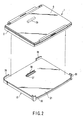
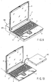
- FIGS. 1 through 5 illustrate the first embodiment of the present invention.
- FIGS. 1 and 2 show a notebook PC 1, which is an example of a portable information device.
- the notebook PC 1 comprises a main body 2.
- a palm rest 3 is formed on the front portion of the upper surface of the main body 2, and a keyboard 4 is located behind the palm rest 3.
- a pair of hinges 5 are provided on the rear portion of the upper surface of the main body 2.
- the lower end of a liquid crystal display 6 is rotatably coupled to the main body 2 by means of the hinges 5.
- the display 6 can be held in an open position at a predetermined angle with respect to the main body 1, as shown in FIG. 1. It also can be held in a closed position to cover the upper surface of the main body 2, as shown in FIG. 2.
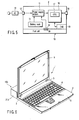
- a power supply section 11 is located inside the main body 2.
- the power supply section 11 is powered by an AC adaptor 13 connected to an AC connector 12.
- the AC connector 12 is provided, for example, on the rear face of the main body 2.
- the power supply section 11 can be powered not only by the AC adaptor 13 described above but also by a secondary battery pack 14 incorporated in the main body 2 and a fuel cell 15.
- the fuel cell 15 is separate from the main body 2 and can be electrically connected thereto, as will be described later.
- the power supply section 11 can be selectively powered by one of the AC adaptor 13, the battery pack 14 and the fuel cell 15.
- the power supply section 11 applies power to a main board 16.
- a CPU 17 is mounted on the main board 16.
- a modem 15, a DVD 19, etc. are connected to the main board 16.
- a DMFC which uses methanol as a liquid fuel, is employed as the fuel cell 15.
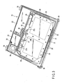
- the fuel cell 15 comprises a casing 21, whose plane figure is substantially the same as that of the main body 2.
- a fuel tank 22 is disposed inside the casing 21, and the fuel tank 22 contains a high concentration of methanol used as a liquid fuel.
- the fuel tank 22 is connected to a mixing tank 23, and a first liquid-supply pump 24 supplies the methanol from the fuel tank 22 to the mixing tank 23.
- the methanol supplied to the mixing tank 23 is diluted to a predetermined concentration with water, which functions as a solvent and is supplied from a pair of fuel cell panels 25 to be described later.
- a second liquid-supply pump 26 is connected to the mixing tank 23. The second liquid-supply pump 26 supplies the diluted methanol toward the anodes of the fuel cell panels 25 through a liquid-supply pipe 27.
- the mixing tank 23 contains diluted methanol, and the two fuel cell panels 25 also contain diluted methanol. Therefore, water (i.e., a solvent) does not have to be supplied to the mixing tank 23.
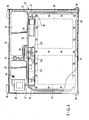
- the liquid-supply pipe 27 includes a main pipe portion 27a and a pair of branch pipe portions 27b.
- the main pipe portion 27a has its one end connected to the outlet portion of the second liquid-supply pump 26.
- the branch pipe portions 27b are symmetric with respect to the other end of the main pipe portion 27a.
- the branch pipe portions 27b are respectively connected to the fuel cell panels 25. In FIG. 4, the branch pipe portions 27b are shown as being connected to the upper side portion of the fuel cell panels 25.
- each of the two fuel cell panels 25 is rectangular.
- the two fuel cell panels 25 are arranged side by side and are held by two holding plates 28 in such a manner that the upper and lower surfaces are in contact with the holding plates 28.
- the two holding plates 28 are secured by means of a plurality of fastening screws 30 located on the peripheral portions of the fuel cell panels 25.
- the present embodiment employs two fuel cell panels 25, and these panels 25 are held between the holding plates 28.
- the holding force is uniformly distributed onto the entire surfaces of the fuel cell panels, and the fuel cell panels 25 are allowed to maintain their desirable performance.
- the liquid-supply pipe 27 has one end connected to the second liquid-supply pump 26 and the other end connected to the two branch pipe portions 27b. Through these branch pipe portions, the liquid-supply pipe 27 is connected to the fuel cell panels 25. In comparison with the case where the two fuel cells 25 are individually connected to piping, the overall length of the piping can be reduced. In addition, the paired fuel cell panels 25 can be supplied with a liquid fuel under the same condition.
- An air-supply pump 29 supplies air through an air-supply tube 31 to the cathode of each fuel cell panel 25.
- the methanol and air supplied to each fuel cell panel 25 react in an electrolyte film, which is located between the anode and the cathode.
- This reaction generates power between the anode and the cathode.
- carbon dioxide is produced from the anode
- water is produced from the cathode.
- the carbon dioxide produced from the anode is supplied from the fuel cell panel 25 to the mixing tank 23 by way of the corresponding one of discharge-liquid tubes 33.
- the water produced from the cathode is supplied through the corresponding one of discharge-gas tubes 32 into the mixing tank 23 in the state of vapor.
- the mixing tank 23 has a discharge section 34 that allows only gas to pass therethrough. The carbon dioxide and the vapor, returned into the mixing tank 23 by way of the discharge-liquid tubes 33 and discharge-gas tubes 32, are discharged from the discharge section 34.
- positioning members 36 are projected from the front end portions and the rear end portions of the periphery of the upper surface of the casing 21 of the fuel cell 15.
- the positioning members 36 serves to position the main body 2 of the notebook PC 1 on the upper surface of the casing 21.
- An opening 37 is formed in a widthwise central portion and somewhat rearward of the upper surface of the casing 21.
- a first connector 38 projects from the opening 37. Power generated by the fuel cell 15 is supplied to the connector 38.
- a second connector 39 is provided on the lower surface of the main body 2.
- the second connector 39 is electrically connected to the first connector 38.
- the second connector 39 does not project from the lower surface of the main body 2 of the notebook PC 1.
- the fuel cell 15 is independent of the main body 2 and can be electrically connected thereto. Therefore, when the notebook PC 1 is used in a place where it can be powered by the AC adaptor 13, the fuel cell 15 may be separated from the main body 2. In this case the overall structure can be compact and light. Consequently, the notebook PC 1 can be handled easily.
- the fuel cell 15 When the notebook PC is in a place where it cannot be powered by the AC adapter 13, the fuel cell 15 is put under the main body 2 as FIG. 1 shows, and the first connector 38 provided on the fuel cell 15 is connected to the second connector 39 provided on the lower surface of the main body 2.
- the notebook PC 1 Since the power generated by the fuel cell 15 can be supplied to the notebook PC 1 in this manner, the notebook PC 1 can be used practically without limitation as long as the liquid fuel is maintained.
- the plane figure of the casing 21 of the fuel cell 15 is substantially the same as that of the main board 2 of the notebook PC 1, under which the fuel cell 15 is located.
- the fuel cell 15 looks integral with the main body 2 in appearance. Therefore, even when the fuel cell 15 is used, it is space-saving and does not impair the appearance of the notebook PC 1.
- the positioning members 36 provided on the four corner portions of the fuel cell 15, serves to locate the notebook PC 1 at a predetermined position relative to the fuel cell 15. Therefore, the second connector 39 provided on the lower surface of the notebook PC 1 can be easily and reliably connected to the first connector 38 provided on the upper surface of the fuel cell 15.
- FIGS. 6 and 7 show the second embodiment of the present invention.
- a fuel cell 15A has a rectangular pillar-shaped casing 21A.
- One side surface of the casing 21A is brought into contact with an outer surface (i.e., the back surface) of the main body 2 of the notebook PC 1.
- a first connector is provided on the side surface of the casing 21A and a second connector is provided on the back surface of the main body 2. These connectors electrically connect the fuel cell 15A and the main body 2.
- a connecting portion 45 to be connected to an external device is formed on the surface opposite to said side surface of the casing 21A that is brought into contact with the main body 2.
- the connecting portion 45 includes a MIKE-IN jack 46, a MIKE-OUT jack 47, an AUX-IN jack 48, a FIR jack 49, a TV-OUT jack 50, a USB jack 51, a parallel port 52, a PC card slot 53, a DC-IN jack 54, a PS/2 jack 55, a modem jack 56, a LAN jack 57, an IEEE (1394) jack 58, a serial port 59, a RGB-OUT port 60, etc.
- the height of the main body 2 does not change whether the fuel cell 15A is attached or not. Therefore, even when the fuel cell 15A is used, the operability of the keyboard 4 does not change.
- the connecting portion 45 is formed on the surface of the fuel cell 15A opposite to the main body 2 side. Therefore, even when the fuel cell 15A is attached to the back surface of the main body 2, it cannot interfere with interconnection between the main body 2 and an external device.
- FIG. 8 shows the third embodiment of the present invention.
- a fuel cell 15B is provided under the main body 2 as in the first embodiment.
- the depth of the fuel cell 15B is substantially half that of the main body 2.
- the fuel cell 15B has a tapered casing 21B, whose thickness gradually decreases from the back end toward the front end. Therefore, when the fuel cell 15B is attached to the lower surface of the main body 2, the main body 2 is supported to incline such that the front end side of the main body 2 is lower than the rear end side thereof.
- the main body 2 can be inclined toward the front end side, since the thickness of the fuel cell 15B gradually decreases. Therefore, even when the fuel cell 15B is provided under the main body 2, the operability of the keyboard 4 on the upper surface of the main body 2 is not compromised.
- FIG. 9 shows the fourth embodiment of the present invention.
- the fuel cell 15 according to the first embodiment is attached to the lower surface of the main body 2 and the fuel cell 15A according to the second embodiment is attached to the back surface of'the main body 2.
- the casing 21A of the fuel cell 15A, attached to the back surface of the main body 2 has a connecting portion (not shown) as shown in FIG. 7.
- FIG. 10 shows the fifth embodiment of the present invention.
- a fuel cell 15C is detachably connected to the main body 2 of the notebook PC 1 by a cable 61.
- This structure allows the fuel cell 15C to be arranged without being limited by the position of the notebook PC 1. Therefore, the notebook PC can be handled more easily.
- the present invention is not limited to the above embodiments but can be modified variously within the scope of the invention.
- the casing 21 of the fuel cell 15 may be tapered such that the thickness thereof gradually decreases from the back end toward the front end.
- the fuel cell 15B is provided on an outer surface (i.e., the back surface) of the main body 2. Instead, however, it may be provided on a side surface perpendicular to the back surface.
- the fuel cell is not limited to the DMFC, but may be another type of cell, such as a PEFC (polymer electrolyte fuel cell).
- PEFC polymer electrolyte fuel cell
Landscapes
- Engineering & Computer Science (AREA)
- Theoretical Computer Science (AREA)
- Computer Hardware Design (AREA)
- General Engineering & Computer Science (AREA)
- Physics & Mathematics (AREA)
- General Physics & Mathematics (AREA)
- Human Computer Interaction (AREA)
- Chemical Kinetics & Catalysis (AREA)
- Power Engineering (AREA)
- General Chemical & Material Sciences (AREA)
- Electrochemistry (AREA)
- Life Sciences & Earth Sciences (AREA)
- Chemical & Material Sciences (AREA)
- Biophysics (AREA)
- Mathematical Physics (AREA)
- Manufacturing & Machinery (AREA)
- Sustainable Development (AREA)
- Sustainable Energy (AREA)
- Fuel Cell (AREA)
- Power Sources (AREA)
Abstract
An information device has a main body (2).
A display (6) is rotatably provided on the main
body (22). A connector (39) is provided on the main
body. A fuel cell (15) is detachably connected to the
connector (39) so that it can apply power to the
connector (39).
Description
The present invention relates to a portable
information device capable of using a fuel cell.
In recent years, it is proposed to use a fuel cell
in a notebook personal computer (hereinafter referred
to as notebook PC), which is an example of a portable
information device. The fuel cell is advantageous in
that it can produce power unlimitedly as long as it is
fueled.
The fuel cell is provided inside the main body of
the notebook PC. Cell batteries of various types are
known, and a DMFC (direct methanol fuel cell) is one of
the known types. The DMFC is a fuel cell which uses
methanol as its liquid fuel (methanol is comparatively
low in price and is easy to handle).
In general, a DMFC comprises the following: a fuel
tank which contains a high concentration of methanol;
a mixing tank in which the methanol supplied from the
fuel tank is diluted with water; a liquid-supply pump
which compressively supplies the methanol diluted in
the mixing tank toward a fuel cell panel; and
an air-supply pump which supplies air toward the fuel
cell panel.
Therefore, the fuel cell is inevitably larger than
a secondary battery, such as a lithium-ion battery,
contained in the notebook PC.
The notebook PC capable of using a fuel cell is
very convenient for a long use in a place where no AC
power source is available. However, owing to the
structure of the main body of the notebook PC,
incorporating a relatively large fuel cell, the main
body is large and heavy. Therefore, the notebook PC of
this type is disadvantageous in handling when the fuel
cell is unnecessary, for example, when the AC power
source is available.
Accordingly, an embodiment of the present
invention may provide an easy-to-handle-portable
information device, which has a fuel cell connectable
to the main body when necessary.
According to an aspect of the present invention,
there is provided an information device comprising:
According to another aspects of the present
invention, since the fuel cell can be electrically
connected to the main body when necessary and detached
therefrom when unnecessary, the information device can
be handled easily.
This summary of the invention does not necessarily
describe all necessary features so that the invention
may also be a sub-combination of these described
features.
The invention can be more fully understood from
the following detailed description when taken in
conjunction with the accompanying drawings, in which:
Embodiments of the present invention will now be
described with reference to the accompanying drawings.
FIGS. 1 through 5 illustrate the first embodiment
of the present invention. FIGS. 1 and 2 show
a notebook PC 1, which is an example of a portable
information device. The notebook PC 1 comprises a main
body 2. A palm rest 3 is formed on the front portion
of the upper surface of the main body 2, and a keyboard
4 is located behind the palm rest 3.
A pair of hinges 5 are provided on the rear
portion of the upper surface of the main body 2. The
lower end of a liquid crystal display 6 is rotatably
coupled to the main body 2 by means of the hinges 5.
The display 6 can be held in an open position at
a predetermined angle with respect to the main body 1,
as shown in FIG. 1. It also can be held in a closed
position to cover the upper surface of the main body 2,
as shown in FIG. 2.
As FIG. 5 shows, a power supply section 11 is
located inside the main body 2. The power supply
section 11 is powered by an AC adaptor 13 connected to
an AC connector 12. The AC connector 12 is provided,
for example, on the rear face of the main body 2.
The power supply section 11 can be powered not
only by the AC adaptor 13 described above but also by
a secondary battery pack 14 incorporated in the main
body 2 and a fuel cell 15. The fuel cell 15 is
separate from the main body 2 and can be electrically
connected thereto, as will be described later.
Thus, the power supply section 11 can be
selectively powered by one of the AC adaptor 13,
the battery pack 14 and the fuel cell 15.
The power supply section 11 applies power to
a main board 16. A CPU 17 is mounted on the main
board 16. A modem 15, a DVD 19, etc. are connected to
the main board 16.
A DMFC, which uses methanol as a liquid fuel, is
employed as the fuel cell 15. As FIGS. 2 to 4 show,
the fuel cell 15 comprises a casing 21, whose plane
figure is substantially the same as that of the main
body 2. As FIGS. 3 and 4 show, a fuel tank 22 is
disposed inside the casing 21, and the fuel tank 22
contains a high concentration of methanol used as a
liquid fuel. The fuel tank 22 is connected to a mixing
tank 23, and a first liquid-supply pump 24 supplies the
methanol from the fuel tank 22 to the mixing tank 23.
The methanol supplied to the mixing tank 23 is
diluted to a predetermined concentration with water,
which functions as a solvent and is supplied from
a pair of fuel cell panels 25 to be described later.
A second liquid-supply pump 26 is connected to the
mixing tank 23. The second liquid-supply pump 26
supplies the diluted methanol toward the anodes of the
fuel cell panels 25 through a liquid-supply pipe 27.
In the initial state, the mixing tank 23 contains
diluted methanol, and the two fuel cell panels 25 also
contain diluted methanol. Therefore, water (i.e.,
a solvent) does not have to be supplied to the mixing
tank 23.
The liquid-supply pipe 27 includes a main pipe
portion 27a and a pair of branch pipe portions 27b.
The main pipe portion 27a has its one end connected to
the outlet portion of the second liquid-supply pump 26.
The branch pipe portions 27b are symmetric with respect
to the other end of the main pipe portion 27a. The
branch pipe portions 27b are respectively connected to
the fuel cell panels 25. In FIG. 4, the branch pipe
portions 27b are shown as being connected to the upper
side portion of the fuel cell panels 25.
As indicated by the dashed lines in FIGS. 3 and 4,
each of the two fuel cell panels 25 is rectangular.
The two fuel cell panels 25 are arranged side by side
and are held by two holding plates 28 in such a manner
that the upper and lower surfaces are in contact with
the holding plates 28. The two holding plates 28 are
secured by means of a plurality of fastening screws 30
located on the peripheral portions of the fuel cell
panels 25.
The present embodiment employs two fuel cell
panels 25, and these panels 25 are held between the
holding plates 28. In comparison with the case where
a single fuel cell panel is employed, the holding force
is uniformly distributed onto the entire surfaces of
the fuel cell panels, and the fuel cell panels 25 are
allowed to maintain their desirable performance.
The liquid-supply pipe 27 has one end connected to
the second liquid-supply pump 26 and the other end
connected to the two branch pipe portions 27b. Through
these branch pipe portions, the liquid-supply pipe 27
is connected to the fuel cell panels 25. In comparison
with the case where the two fuel cells 25 are
individually connected to piping, the overall length of
the piping can be reduced. In addition, the paired
fuel cell panels 25 can be supplied with a liquid fuel
under the same condition.
An air-supply pump 29 supplies air through
an air-supply tube 31 to the cathode of each fuel cell
panel 25. The methanol and air supplied to each fuel
cell panel 25 react in an electrolyte film, which is
located between the anode and the cathode.
This reaction generates power between the anode
and the cathode. Simultaneously, carbon dioxide is
produced from the anode, and water is produced from the
cathode. The carbon dioxide produced from the anode is
supplied from the fuel cell panel 25 to the mixing tank
23 by way of the corresponding one of discharge-liquid
tubes 33. On the other hand, the water produced from
the cathode is supplied through the corresponding one
of discharge-gas tubes 32 into the mixing tank 23 in
the state of vapor. The mixing tank 23 has a discharge
section 34 that allows only gas to pass therethrough.
The carbon dioxide and the vapor, returned into the
mixing tank 23 by way of the discharge-liquid tubes 33
and discharge-gas tubes 32, are discharged from the
discharge section 34.
As FIG. 2 shows, positioning members 36 are
projected from the front end portions and the rear end
portions of the periphery of the upper surface of
the casing 21 of the fuel cell 15. The positioning
members 36 serves to position the main body 2 of the
notebook PC 1 on the upper surface of the casing 21.
An opening 37 is formed in a widthwise central portion
and somewhat rearward of the upper surface of the
casing 21. A first connector 38 projects from the
opening 37. Power generated by the fuel cell 15 is
supplied to the connector 38.
A second connector 39 is provided on the lower
surface of the main body 2. When the main body 2 is
positioned by the positioning members 36 and put on the
upper surface of the casing 21 of the fuel cell 15, the
second connector 39 is electrically connected to the
first connector 38. As a result, the power generated
by the fuel cell 15 is supplied to the power supply
section 11 of the notebook PC 1. The second connector
39 does not project from the lower surface of the main
body 2 of the notebook PC 1.
In the notebook PC 1 with the above structure, the
fuel cell 15 is independent of the main body 2 and can
be electrically connected thereto. Therefore, when the
notebook PC 1 is used in a place where it can be
powered by the AC adaptor 13, the fuel cell 15 may be
separated from the main body 2. In this case the
overall structure can be compact and light.
Consequently, the notebook PC 1 can be handled easily.
When the notebook PC is in a place where it cannot
be powered by the AC adapter 13, the fuel cell 15 is
put under the main body 2 as FIG. 1 shows, and the
first connector 38 provided on the fuel cell 15 is
connected to the second connector 39 provided on the
lower surface of the main body 2.
Since the power generated by the fuel cell 15 can
be supplied to the notebook PC 1 in this manner, the
notebook PC 1 can be used practically without
limitation as long as the liquid fuel is maintained.
The plane figure of the casing 21 of the fuel cell
15 is substantially the same as that of the main board
2 of the notebook PC 1, under which the fuel cell 15 is
located. Thus, the fuel cell 15 looks integral with
the main body 2 in appearance. Therefore, even when
the fuel cell 15 is used, it is space-saving and does
not impair the appearance of the notebook PC 1.
The positioning members 36, provided on the four
corner portions of the fuel cell 15, serves to locate
the notebook PC 1 at a predetermined position relative
to the fuel cell 15. Therefore, the second connector
39 provided on the lower surface of the notebook PC 1
can be easily and reliably connected to the first
connector 38 provided on the upper surface of the fuel
cell 15.
FIGS. 6 and 7 show the second embodiment of the
present invention. In this embodiment, a fuel cell 15A
has a rectangular pillar-shaped casing 21A. One side
surface of the casing 21A is brought into contact with
an outer surface (i.e., the back surface) of the main
body 2 of the notebook PC 1. Although not shown,
a first connector is provided on the side surface of
the casing 21A and a second connector is provided on
the back surface of the main body 2. These connectors
electrically connect the fuel cell 15A and the main
body 2.
As FIG. 7 shows, a connecting portion 45 to be
connected to an external device is formed on the
surface opposite to said side surface of the casing 21A
that is brought into contact with the main body 2.
The connecting portion 45 includes a MIKE-IN jack 46,
a MIKE-OUT jack 47, an AUX-IN jack 48, a FIR jack 49,
a TV-OUT jack 50, a USB jack 51, a parallel port 52,
a PC card slot 53, a DC-IN jack 54, a PS/2 jack 55,
a modem jack 56, a LAN jack 57, an IEEE (1394) jack 58,
a serial port 59, a RGB-OUT port 60, etc.
Since the fuel cell 15A is attached to the back
surface of the main body 2, the height of the main
body 2 does not change whether the fuel cell 15A is
attached or not. Therefore, even when the fuel
cell 15A is used, the operability of the keyboard 4
does not change.
In addition, the connecting portion 45 is formed
on the surface of the fuel cell 15A opposite to the
main body 2 side. Therefore, even when the fuel cell
15A is attached to the back surface of the main body 2,
it cannot interfere with interconnection between the
main body 2 and an external device.
FIG. 8 shows the third embodiment of the present
invention. In this embodiment, a fuel cell 15B is
provided under the main body 2 as in the first
embodiment. However, the depth of the fuel cell 15B is
substantially half that of the main body 2.
The fuel cell 15B has a tapered casing 21B, whose
thickness gradually decreases from the back end toward
the front end. Therefore, when the fuel cell 15B is
attached to the lower surface of the main body 2, the
main body 2 is supported to incline such that the front
end side of the main body 2 is lower than the rear end
side thereof.
When the fuel cell 15B is provided on the lower
surface of the main body 2, the main body 2 can be
inclined toward the front end side, since the thickness
of the fuel cell 15B gradually decreases. Therefore,
even when the fuel cell 15B is provided under the main
body 2, the operability of the keyboard 4 on the upper
surface of the main body 2 is not compromised.
FIG. 9 shows the fourth embodiment of the present
invention. In this embodiment, the fuel cell 15
according to the first embodiment is attached to the
lower surface of the main body 2 and the fuel cell 15A
according to the second embodiment is attached to the
back surface of'the main body 2. As in the second
embodiment, the casing 21A of the fuel cell 15A,
attached to the back surface of the main body 2, has
a connecting portion (not shown) as shown in FIG. 7.
FIG. 10 shows the fifth embodiment of the present
invention. In this embodiment, a fuel cell 15C is
detachably connected to the main body 2 of the notebook
PC 1 by a cable 61.
This structure allows the fuel cell 15C to be
arranged without being limited by the position of the
notebook PC 1. Therefore, the notebook PC can be
handled more easily.
The present invention is not limited to the above
embodiments but can be modified variously within the
scope of the invention. For example, in the first and
fourth embodiments, in which the fuel cell 15 is
provided on the overall lower surface of the main
body 2, the casing 21 of the fuel cell 15 may be
tapered such that the thickness thereof gradually
decreases from the back end toward the front end.
With this structure, even if the fuel cell 15 is
provided on the overall lower surface the main body 2,
the operability of the keyboard 4 on the upper surface
of the main body 2 can be improved.
In the second embodiment shown in FIG. 6, the fuel
cell 15B is provided on an outer surface (i.e., the
back surface) of the main body 2. Instead, however, it
may be provided on a side surface perpendicular to the
back surface.
The fuel cell is not limited to the DMFC, but may
be another type of cell, such as a PEFC (polymer
electrolyte fuel cell).
Claims (11)
- An information device characterized by comprising:a main body (2);a display (6) rotatably provided on the main body (2);a fuel cell (15) detachably connected to the main body (2), the fuel cell (15) being capable of applying power to the main body (12); anda connector (39) which is provided on a surface of the main body (2), and electrically connected to and powered by the fuel cell (15).
- The information device according to claim 1, characterized in that the fuel cell (15) is electrically connectable to a lower surface of the main body (2).
- The information device according to claim 1, characterized in that the fuel cell (15A) is electrically connectable to an outer surface of the main body (2).
- The information device according to claim 3, characterized in that the fuel cell (15A) is electrically connectable to the main body (2) such that one surface thereof faces a back surface of the main body (2), and another surface of the fuel cell (15) has a connecting portion (45) to be connected with an external device.
- The information device according to claim 1, characterized in that the fuel cell (15, 15A) is electrically connectable to a lower surface and an outer surface of the main body (12).
- The information device according to claim 1, characterized in that the fuel cell (15B) is tapered such that thickness thereof decreases from a rear end of the main body (2) toward a front end thereof, and electrically connectable to a rear portion of a lower surface of the main body (2).
- The information device according to claim 1, characterized in that the fuel cell (15) has a casing (21), which includes a fuel tank (22) containing a liquid fuel, a mixing tank (23) in which the liquid fuel supplied from the fuel tank (22) is diluted with solvent, two fuel cell panels (25) arranged side by side and held between two holding plates (28), a liquid-supply pipe (27) having one end connected to the mixing tank (23) via a liquid-supply pump (26) and another end divided into two branches respectively connected to the two fuel cell panels (25), an air-supply pump (29) which supplies air to the two fuel cell panels (25), and an gas discharge pipe (31) and a liquid discharge pipe (33) which respectively return gas and liquid discharged from the two fuel cell panels (25) to the mixing tank (23).
- An information device characterized by comprising:a main body (2);a display (6) rotatably provided on the main body (2);a fuel cell (15) to power the main body (2);a first connector (38) which is provided on an upper surface of the fuel cell (15); anda second connector (39) which is provided on a lower surface of the main body (2), and detachably and electrically connected to the first connector (38) to apply power generated by the fuel cell (15) to the main body (2), when the upper surface of the fuel cell (15) is connected to the lower surface of the main body (2).
- The information device according to claim 8, characterized in that the fuel cell (15) has a plane figure substantially same in dimensions as that of the main body (2).
- The information device according to claim 9, characterized by further comprising positioning members (36) provided on four corner portions of the fuel cell (15), which position the second connector (39) to a position where it is connected to the first connector (38).
- The information device according to claim 8, characterized by further comprising an AC adapter (127) and a battery pack (14) connected to the main body (2), wherein the main body (2) is selectively powered by one of the AC adapter (127), the battery pack (14) and the fuel cell (15).
Applications Claiming Priority (2)
| Application Number | Priority Date | Filing Date | Title |
|---|---|---|---|
| JP2002020361 | 2002-01-29 | ||
| JP2002020361A JP2003223243A (en) | 2002-01-29 | 2002-01-29 | Information equipment |
Publications (1)
| Publication Number | Publication Date |
|---|---|
| EP1331680A2 true EP1331680A2 (en) | 2003-07-30 |
Family
ID=19192159
Family Applications (1)
| Application Number | Title | Priority Date | Filing Date |
|---|---|---|---|
| EP03001124A Withdrawn EP1331680A2 (en) | 2002-01-29 | 2003-01-20 | Portable information device capable of using fuel cell |
Country Status (3)
| Country | Link |
|---|---|
| US (1) | US20030142467A1 (en) |
| EP (1) | EP1331680A2 (en) |
| JP (1) | JP2003223243A (en) |
Cited By (3)
| Publication number | Priority date | Publication date | Assignee | Title |
|---|---|---|---|---|
| FR2866692A1 (en) * | 2004-02-25 | 2005-08-26 | Tatung Co Ltd | DEVICE FOR ADJUSTING THE HEIGHT OF A PORTABLE INFORMATION PRESENTATION APPARATUS |
| JP2007242606A (en) * | 2006-02-14 | 2007-09-20 | Angstrom Power Inc | Fuel cell device and its method |
| GB2531702A (en) * | 2014-10-15 | 2016-05-04 | Intelligent Energy Ltd | Fuel source for electrochemical fuel cell power supply |
Families Citing this family (20)
| Publication number | Priority date | Publication date | Assignee | Title |
|---|---|---|---|---|
| JP3704123B2 (en) * | 2002-12-27 | 2005-10-05 | 株式会社東芝 | Electronic equipment and battery unit |
| JP3720024B2 (en) * | 2003-01-10 | 2005-11-24 | 株式会社東芝 | Electronic device system and operation control method |
| JP3764426B2 (en) * | 2003-01-21 | 2006-04-05 | 株式会社東芝 | Electronic device and operation control method |
| JP2004227139A (en) * | 2003-01-21 | 2004-08-12 | Toshiba Corp | Electronic device and operation control method thereof |
| JP3842744B2 (en) * | 2003-02-28 | 2006-11-08 | 株式会社東芝 | Electronic device and power supply status display method for the same |
| JP3764429B2 (en) * | 2003-02-28 | 2006-04-05 | 株式会社東芝 | Electronic device and power supply switching control method for electronic device |
| JP3713496B2 (en) * | 2003-03-25 | 2005-11-09 | 株式会社東芝 | Electronic device and power control method for electronic device |
| KR100512736B1 (en) * | 2003-06-25 | 2005-09-07 | 삼성전자주식회사 | Portable Computer |
| JP4525015B2 (en) * | 2003-07-07 | 2010-08-18 | ソニー株式会社 | Electronics |
| JP2005078353A (en) * | 2003-08-29 | 2005-03-24 | Toshiba Corp | Electronic device system and power supply method |
| JP3989471B2 (en) | 2003-09-12 | 2007-10-10 | 三洋電機株式会社 | Fuel cell device |
| JP4867345B2 (en) | 2003-11-06 | 2012-02-01 | 日本電気株式会社 | Fuel cartridge for fuel cell and fuel cell having the same |
| US7245951B2 (en) * | 2004-03-23 | 2007-07-17 | General Motors Corporation | Method and system for telematic data transfer |
| JP4296118B2 (en) * | 2004-03-31 | 2009-07-15 | 株式会社東芝 | Information processing apparatus system and charging control method |
| JP2005294065A (en) * | 2004-03-31 | 2005-10-20 | Toshiba Corp | FUEL CELL UNIT, INFORMATION PROCESSING DEVICE, AND INFORMATION CONTROL DEVICE POWER SUPPLY CONTROL METHOD |
| JP4551685B2 (en) * | 2004-03-31 | 2010-09-29 | 株式会社東芝 | Information processing apparatus and information processing apparatus control method |
| US7736773B2 (en) * | 2004-04-16 | 2010-06-15 | Anton/Bauer, Inc. | Dual power supply for electronic devices |
| JP4583906B2 (en) * | 2004-12-17 | 2010-11-17 | Necパーソナルプロダクツ株式会社 | Electronic devices and systems using fuel cells |
| JP2007026832A (en) * | 2005-07-14 | 2007-02-01 | Toshiba Corp | Information processing apparatus and operation control method |
| US8133621B2 (en) | 2009-02-27 | 2012-03-13 | Research In Motion Limited | Location of a fuel cell on a mobile device |
Family Cites Families (2)
| Publication number | Priority date | Publication date | Assignee | Title |
|---|---|---|---|---|
| US6259971B1 (en) * | 1997-06-30 | 2001-07-10 | Compaq Computer Corporation | Portable fuel-cell-powered system with ultrasonic atomization of H2O by-product |
| US6326097B1 (en) * | 1998-12-10 | 2001-12-04 | Manhattan Scientifics, Inc. | Micro-fuel cell power devices |
-
2002
- 2002-01-29 JP JP2002020361A patent/JP2003223243A/en active Pending
-
2003
- 2003-01-20 EP EP03001124A patent/EP1331680A2/en not_active Withdrawn
- 2003-01-28 US US10/352,057 patent/US20030142467A1/en not_active Abandoned
Cited By (5)
| Publication number | Priority date | Publication date | Assignee | Title |
|---|---|---|---|---|
| FR2866692A1 (en) * | 2004-02-25 | 2005-08-26 | Tatung Co Ltd | DEVICE FOR ADJUSTING THE HEIGHT OF A PORTABLE INFORMATION PRESENTATION APPARATUS |
| JP2007242606A (en) * | 2006-02-14 | 2007-09-20 | Angstrom Power Inc | Fuel cell device and its method |
| EP1821031A3 (en) * | 2006-02-14 | 2007-11-21 | Angstrom Power Inc. | Fuel cell devices and method therefor |
| US7964313B2 (en) | 2006-02-14 | 2011-06-21 | Angstrom Power Incorporated | Fuel cell devices and method therefor |
| GB2531702A (en) * | 2014-10-15 | 2016-05-04 | Intelligent Energy Ltd | Fuel source for electrochemical fuel cell power supply |
Also Published As
| Publication number | Publication date |
|---|---|
| JP2003223243A (en) | 2003-08-08 |
| US20030142467A1 (en) | 2003-07-31 |
Similar Documents
| Publication | Publication Date | Title |
|---|---|---|
| EP1331680A2 (en) | Portable information device capable of using fuel cell | |
| US7158375B2 (en) | Portable computer system | |
| US7026066B2 (en) | Electronic apparatus using fuel cell | |
| US20030161096A1 (en) | Portable computer docking tray system | |
| CN1806363A (en) | Fuel cartridge interconnect for portable fuel cells | |
| CN100544086C (en) | Fuel cell device and method therefor | |
| US20140009111A1 (en) | Charger, electronic apparatus, and storage case | |
| JP3773910B2 (en) | Fuel cell unit for electronic equipment | |
| JP2010015854A (en) | Fuel cell housing structure and electronic device | |
| US20040066611A1 (en) | Computer keyboard with backup battery | |
| CN101169677A (en) | laptop | |
| US6495987B2 (en) | Battery module that further serves as a handle for a portable computer | |
| CN100426621C (en) | Electronic apparatus system, and operation control method | |
| JP2005108812A (en) | Fuel tank | |
| US20110300468A1 (en) | Fuel cell device | |
| JP4004489B2 (en) | Fuel cell system | |
| US7117906B2 (en) | Datum based interchangeable fuel cell cartridges | |
| JP2005108814A (en) | Fuel cell device | |
| US20070298300A1 (en) | Fuel cell device with charger function | |
| US7620805B2 (en) | Apparatus for updating program in a fuel cell unit | |
| US20060246339A1 (en) | Fuel cell unit and electronic apparatus | |
| JP2010134786A (en) | Electronic apparatus | |
| US7832989B2 (en) | Pump applied to fuel storage device and portable device with fuel storage device for fuel cells | |
| TWI377476B (en) | Notebook computer | |
| US20060068241A1 (en) | Information processing apparatus system, fuel cell unit, and display method thereof |
Legal Events
| Date | Code | Title | Description |
|---|---|---|---|
| PUAI | Public reference made under article 153(3) epc to a published international application that has entered the european phase |
Free format text: ORIGINAL CODE: 0009012 |
|
| 17P | Request for examination filed |
Effective date: 20030120 |
|
| AK | Designated contracting states |
Designated state(s): AT BE BG CH CY CZ DE DK EE ES FI FR GB GR HU IE IT LI LU MC NL PT SE SI SK TR |
|
| AX | Request for extension of the european patent |
Extension state: AL LT LV MK RO |
|
| STAA | Information on the status of an ep patent application or granted ep patent |
Free format text: STATUS: THE APPLICATION HAS BEEN WITHDRAWN |
|
| 18W | Application withdrawn |
Effective date: 20050519 |