EP1331678A2 - Sealed prismatic battery and battery module - Google Patents
Sealed prismatic battery and battery module Download PDFInfo
- Publication number
- EP1331678A2 EP1331678A2 EP03250506A EP03250506A EP1331678A2 EP 1331678 A2 EP1331678 A2 EP 1331678A2 EP 03250506 A EP03250506 A EP 03250506A EP 03250506 A EP03250506 A EP 03250506A EP 1331678 A2 EP1331678 A2 EP 1331678A2
- Authority
- EP
- European Patent Office
- Prior art keywords
- connection
- electrode plate
- battery case
- battery
- plate group
- Prior art date
- Legal status (The legal status is an assumption and is not a legal conclusion. Google has not performed a legal analysis and makes no representation as to the accuracy of the status listed.)
- Granted
Links
Images





Classifications
-
- H—ELECTRICITY
- H01—ELECTRIC ELEMENTS
- H01M—PROCESSES OR MEANS, e.g. BATTERIES, FOR THE DIRECT CONVERSION OF CHEMICAL ENERGY INTO ELECTRICAL ENERGY
- H01M50/00—Constructional details or processes of manufacture of the non-active parts of electrochemical cells other than fuel cells, e.g. hybrid cells
- H01M50/50—Current conducting connections for cells or batteries
- H01M50/528—Fixed electrical connections, i.e. not intended for disconnection
- H01M50/529—Intercell connections through partitions, e.g. in a battery casing
-
- H—ELECTRICITY
- H01—ELECTRIC ELEMENTS
- H01M—PROCESSES OR MEANS, e.g. BATTERIES, FOR THE DIRECT CONVERSION OF CHEMICAL ENERGY INTO ELECTRICAL ENERGY
- H01M50/00—Constructional details or processes of manufacture of the non-active parts of electrochemical cells other than fuel cells, e.g. hybrid cells
- H01M50/10—Primary casings; Jackets or wrappings
- H01M50/172—Arrangements of electric connectors penetrating the casing
- H01M50/174—Arrangements of electric connectors penetrating the casing adapted for the shape of the cells
- H01M50/176—Arrangements of electric connectors penetrating the casing adapted for the shape of the cells for prismatic or rectangular cells
-
- H—ELECTRICITY
- H01—ELECTRIC ELEMENTS
- H01M—PROCESSES OR MEANS, e.g. BATTERIES, FOR THE DIRECT CONVERSION OF CHEMICAL ENERGY INTO ELECTRICAL ENERGY
- H01M50/00—Constructional details or processes of manufacture of the non-active parts of electrochemical cells other than fuel cells, e.g. hybrid cells
- H01M50/50—Current conducting connections for cells or batteries
- H01M50/531—Electrode connections inside a battery casing
- H01M50/533—Electrode connections inside a battery casing characterised by the shape of the leads or tabs
-
- H—ELECTRICITY
- H01—ELECTRIC ELEMENTS
- H01M—PROCESSES OR MEANS, e.g. BATTERIES, FOR THE DIRECT CONVERSION OF CHEMICAL ENERGY INTO ELECTRICAL ENERGY
- H01M50/00—Constructional details or processes of manufacture of the non-active parts of electrochemical cells other than fuel cells, e.g. hybrid cells
- H01M50/50—Current conducting connections for cells or batteries
- H01M50/543—Terminals
- H01M50/552—Terminals characterised by their shape
- H01M50/553—Terminals adapted for prismatic, pouch or rectangular cells
-
- H—ELECTRICITY
- H01—ELECTRIC ELEMENTS
- H01M—PROCESSES OR MEANS, e.g. BATTERIES, FOR THE DIRECT CONVERSION OF CHEMICAL ENERGY INTO ELECTRICAL ENERGY
- H01M10/00—Secondary cells; Manufacture thereof
- H01M10/04—Construction or manufacture in general
- H01M10/0413—Large-sized flat cells or batteries for motive or stationary systems with plate-like electrodes
-
- H—ELECTRICITY
- H01—ELECTRIC ELEMENTS
- H01M—PROCESSES OR MEANS, e.g. BATTERIES, FOR THE DIRECT CONVERSION OF CHEMICAL ENERGY INTO ELECTRICAL ENERGY
- H01M10/00—Secondary cells; Manufacture thereof
- H01M10/34—Gastight accumulators
- H01M10/345—Gastight metal hydride accumulators
-
- H—ELECTRICITY
- H01—ELECTRIC ELEMENTS
- H01M—PROCESSES OR MEANS, e.g. BATTERIES, FOR THE DIRECT CONVERSION OF CHEMICAL ENERGY INTO ELECTRICAL ENERGY
- H01M50/00—Constructional details or processes of manufacture of the non-active parts of electrochemical cells other than fuel cells, e.g. hybrid cells
- H01M50/10—Primary casings; Jackets or wrappings
- H01M50/102—Primary casings; Jackets or wrappings characterised by their shape or physical structure
- H01M50/103—Primary casings; Jackets or wrappings characterised by their shape or physical structure prismatic or rectangular
-
- Y—GENERAL TAGGING OF NEW TECHNOLOGICAL DEVELOPMENTS; GENERAL TAGGING OF CROSS-SECTIONAL TECHNOLOGIES SPANNING OVER SEVERAL SECTIONS OF THE IPC; TECHNICAL SUBJECTS COVERED BY FORMER USPC CROSS-REFERENCE ART COLLECTIONS [XRACs] AND DIGESTS
- Y02—TECHNOLOGIES OR APPLICATIONS FOR MITIGATION OR ADAPTATION AGAINST CLIMATE CHANGE
- Y02E—REDUCTION OF GREENHOUSE GAS [GHG] EMISSIONS, RELATED TO ENERGY GENERATION, TRANSMISSION OR DISTRIBUTION
- Y02E60/00—Enabling technologies; Technologies with a potential or indirect contribution to GHG emissions mitigation
- Y02E60/10—Energy storage using batteries
-
- Y—GENERAL TAGGING OF NEW TECHNOLOGICAL DEVELOPMENTS; GENERAL TAGGING OF CROSS-SECTIONAL TECHNOLOGIES SPANNING OVER SEVERAL SECTIONS OF THE IPC; TECHNICAL SUBJECTS COVERED BY FORMER USPC CROSS-REFERENCE ART COLLECTIONS [XRACs] AND DIGESTS
- Y02—TECHNOLOGIES OR APPLICATIONS FOR MITIGATION OR ADAPTATION AGAINST CLIMATE CHANGE
- Y02P—CLIMATE CHANGE MITIGATION TECHNOLOGIES IN THE PRODUCTION OR PROCESSING OF GOODS
- Y02P70/00—Climate change mitigation technologies in the production process for final industrial or consumer products
- Y02P70/50—Manufacturing or production processes characterised by the final manufactured product
Definitions
- the present invention relates to a sealed prismatic battery and a battery module having a plurality of sealed prismatic batteries integrally connected to one another, and particularly to a sealed prismatic battery and a battery module with lower internal resistance.
- a conventional battery module is constructed of a plurality of cells that are formed in the shape of a rectangular prism and connected to each other to provide the required power capacity.
- the cells are arranged such that the longer lateral walls of their battery cases are placed adjacent to each other.
- Those cells disposed at both ends in this arrangement are each provided with an end plate on the exterior of their respective cases and then united by restraining bands together.
- leads extending upwardly from the top ends of electrode plates are connected to their respective terminals mounted in the lid of the battery case, with all the terminals of the cells being connected to each other via connection plates.
- this arrangement has a long connection path and a number of connections between the cells, thereby causing a high resistance derived from their components including their connection components.
- This high internal resistance causes a large amount of heat to be generated in the cells. Consequently, there was an obstacle to implementation of high power output and improvement in the battery life characteristics.
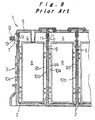
- the battery module 1 has a prismatic battery case 3 constructed in the shape of a flat rectangular prism in which cell cases 4 of the prismatic cells 2, each cell case having short lateral walls and long lateral walls, are coupled integrally to each other with the short lateral walls shared as partition walls 5.
- the open top ends of the cell cases 4 are covered with an integral lid 6.
- connection holes 7 are formed in an upper portion of each partition wall 5 and in the short lateral walls of the cell cases 4 disposed at both ends of the battery module 1.
- an electrode plate group 8 which has rectangular positive and negative electrode plates stacked upon one another with separators interposed in therebetween is accommodated in conjunction with a liquid electrolyte.
- the cells 2 are constructed in this manner.
- the positive and negative electrode plates in the electrode plate group 8 are protruded to the sides opposite to each other and serve as positive and negative electrode leads 9a, 9b, respectively, to the respective side edges of which collector plates 10a, 10b are connected by welding or the like.
- connection boss 11 that fits into the connection hole 7, such that the connection bosses 11 of the positive and negative collector plates 10a, 10b are connected by welding to each other between adjacent cell cases 4, 4.
- connection bosses 13 of the connection terminals 12 are connected by welding to the connection bosses 11 of the collector plates 10a, 10b, respectively.
- connection path takes a detour thereby being elongated.
- connection bosses 11 are connected to each other at one location, thereby presenting a problem of providing a high internal resistance.
- connection path since the connection path takes a detour, a large amount of current flows through the electrode plate group 8 near the connection bosses of the collector plates 10a, 10b whereas a small amount of current flows therethrough away from the connection bosses. This causes the electrode plate group 8 to provide an uneven distribution of current flowing therethrough and uneven power output, thus leading to power loss.
- the present invention has been developed in light of the aforementioned conventional problems. It is therefore an object of the invention to provide a sealed prismatic battery and a battery module having a plurality of sealed prismatic batteries connected to one another, which are reduced in internal resistance and the electrode plate group makes uniform use of their capabilities to provide high power output.
- a sealed prismatic battery according to the present invention includes:
- this construction eliminates other additional connection members or connection points with the collector having a short current flow path, thereby providing the sealed prismatic battery having a reduced internal resistance. Furthermore, when there is provided a connection boss at the middle on the collector and particularly when a plurality of connection bosses are formed thereon, this construction provides an even distribution of current flowing through the electrode plate group to allow the electrode plate group to make uniform use of each power supply capability to provide high power output.
- a plurality of the sealed prismatic batteries can be formed into the battery module such that those connection bosses having opposite polarities are abutted and welded to each other.
- This construction provides a battery module that has a predetermined power capacity, a reduced internal resistance as described above, and the electrode plate groups making uniform use of their power supply capabilities.
- a sealed prismatic battery 20 which includes a battery case 21 made of synthetic resin such as an alloy of PP and PPE, having resistance to liquid electrolyte.
- the battery case 21 is formed in the shape of a sealed rectangular prism.
- the battery case 21 has a battery case body 22 having an opening on one short lateral side and a cover assembly 23 for covering the opening, the battery case body 22 and the cover assembly 23 being integrally welded.
- a short lateral wall 22a is opposite to the opening of the battery case body 22.
- Projections 22b are disposed at appropriate intervals on the long lateral walls of the battery case body 22 in order to form a coolant pathway between the sealed prismatic batteries 20 arranged in parallel to one another.
- an electrode plate group 25 having collectors 26 each connected to an end thereof are housed in the battery case 21 in conjunction with a liquid electrolyte, thereby forming a cell.
- the electrode plate group 25 is constructed such that a plurality of positive electrode plates and a plurality of negative electrode plates are alternately stacked upon one another with a bag-shaped separator, having an opening in a lateral direction, disposed between the positive and negative electrode plates, each positive electrode plate being covered with the separator.
- One side of the positive electrode plates is projected in one direction and the other side of the negative electrode plates is projected in the other direction, and the sides are each provided with their respective positive and negative electrode lead portions, on each of which provided is the collector 26 formed of a steel plate that is plated with nickel.
- the positive electrode plate is made of a nickel foam metal coated with nickel hydroxide except for the lead portion.
- the lead portion is constructed such that a compression pressure is applied to the foam metal and a lead plate is ultrasonically seam-welded onto a surface thereof.
- the negative electrode plate is made of a nickel punched metal coated with negative electrode constituent materials including hydrogen-absorption alloy except for the lead portion.
- the electrode plate group 25 is not limited to such a construction in which a plurality of rectangular positive and negative electrode plates are stacked upon another with the separators interposed therebetween.
- Positive and negative electrode strips each having a lead portion on the sides opposite to each other, can be stacked upon another with separators interposed therebetween and then wound in the shape of an ellipse in cross section or in the shape of a substantial rectangle with a separator placed on the top or bottom of the stack.
- the battery case 21 can be nearly elliptic or approximately rectangular in longitudinal section.
- the collectors 26 and the lead portions of the electrode plate group 25 are welded to each other by electron beam welding at joint portions 27 that are provided on the collectors 26 at a plurality of portions (at three portions in the drawing, i.e., at the upper, middle, and lower portions) at appropriate vertical intervals.
- joint portions 27 that are provided on the collectors 26 at a plurality of portions (at three portions in the drawing, i.e., at the upper, middle, and lower portions) at appropriate vertical intervals.
- corresponding to the recessed portions 28 there are formed lateral recessed portions 29 on both short lateral sides of the battery case 21 or on the short lateral wall 22a and the cover assembly 23.
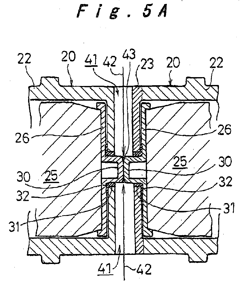
- connection bosses 30 at the center of each recessed portion 28 on the collectors 26, while through-holes 31, through which the connection bosses 30 pierce, are formed at the center of each recessed portion 29 of the battery case 21.
- the connection bosses 30 are designed in height to be generally flush at their tip with the outer surface of the short lateral wall of the battery case 21.
- the vertical dimensions of the recessed portions 28, 29 are designed to provide an appropriate space, above or below the connection bosses 30 or the through-holes 31, which is just enough to allow for connecting between the connection bosses 30, 30, discussed later.
- connection boss 30 As shown in Fig. 2, a rubber seal 32 that serves as a seal member is interposed between the connection boss 30 and the through-hole 31 to ensure the sealing of the battery case 21. Additionally, the connection boss 30 is coated on the outer circumference thereof with a sealant 33 such as pitch to ensure the sealing between the connection boss 30 and the rubber seal 32.
- the sealed prismatic battery 20 having the aforementioned construction is manufactured as follows. As shown in Fig. 3, the electrode plate group 25 is formed, and the collectors 26 are then disposed on both sides thereof and joined together at the joint portions 27. Thereafter, as shown in Fig. 2, the sealant 33 is applied around the outer circumference of the connection bosses 30, over which the rubber seals 32 are press fitted. With this arrangement, the electrode plate group 25 is inserted into the battery case body 22. The opening of the battery case body 22 is covered with the cover assembly 23, which is then welded to the battery case body 22, to thereby form the sealed battery case 21. Then, after a liquid electrolyte is dispensed through the safety vent hole 24, a safety vent is attached thereto, thus providing a complete sealed prismatic battery 20 serving as a cell as shown in Fig. 1.
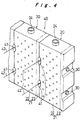
- a predetermined number of sealed prismatic batteries 20 described above are connected to one another to form a battery module 40. That is, a predetermined number of sealed prismatic batteries 20 are formed into the battery module 40 such that the short lateral walls of the batteries on which the connection bosses 30 are provided are opposed to one another, and then the tips of the connection bosses 30, 30 abutting to each other are irradiated with a laser beam or an electron beam 42 through a joint space 41 provided by the recessed portions 29.
- mating portions are preferably provided to allow the short lateral wall 22a and the cover assembly 23 to mate with each other when abutted to each other.
- connection plate 44 on the upper portion of which provided is an electrode pole 45 is abutted to the outer side, having the connection bosses 30 thereon, of the sealed prismatic batteries 20 disposed at both ends of the battery module 40.
- This arrangement allows the connection plate 44 and the connection bosses 30 to be welded to each other at joint portions 46 by resistance welding or laser welding. It is thus made possible to apply this general connection arrangement employing the electrode pole 45 to connect the battery module 40 to an external circuit or the like.
- connection bosses 30 formed in a middle part of the collector 26 penetrate the battery case 21 to serve as connections with the outside. Accordingly, this construction has no other additional connection members or connection points with the collector 26 having a short current flow path, thereby providing the sealed prismatic battery 20 having a reduced internal resistance. Furthermore, there are provided a plurality of connection bosses 30 spaced appropriately from one another evenly on the collector 26. This provides an even distribution of current flowing through the electrode plate group 25 to allow the electrode plate group 25 to make uniform use of each power supply capability to provide high power output.
- a plurality of sealed prismatic batteries 20 are formed into the battery module 40 such that those connection bosses 30, 30 having opposite polarities are abutted and welded to one another at welding portions 43.
- This construction provides a battery module that has a predetermined power capacity, a reduced internal resistance, and an electrode plate group making uniform use of its power supply capabilities.
- the electrode plate group 25 and the collector 26 are connected to each other at a plurality of joint portions 27 disposed at appropriate intervals on the collector 26 in the longitudinal direction thereof, with the connection bosses 30 disposed in between the joint portions 27, 27.
- the current flow path from the outside to the electrode plate group 25 leads from the connection boss 30 through the collector 26 to the joint portion 27 between both the electrode plate groups 25, thereby allowing current to flow through a short current flow path and from a plurality of joint portions 27 to the electrode plate group 25.
- This allows the distribution of current flowing through the electrode plate group 25 to be further equalized as well as the electrode plate group 25 to make uniform use of its power supply capabilities and provide high power output.
- the portions, having the connection bosses 30 thereon, of the short lateral wall 22a of the battery case body 22 and the cover assembly 23 are formed on the recessed portions 29 that extend in the lateral direction thereof and are recessed by the amount of projection of the connection bosses 30.
- the connection bosses 30 can be irradiated with the laser beam or electron beam 42 in the lateral direction of the joint space 41 defined by the recessed portions 29 and can thereby be connected to each other at the welding portions 43. Accordingly, it is possible to connect the connection bosses 30 to one another with good productivity and high reliability. Additionally, since the connections of the connection bosses 30 are located inside the recessed portions 29, the battery case 21 provides protection thereto.
- the recessed portions 28 are formed on the collectors 26 and the connection edges of the electrode plate group 25 connected to the collectors 26. Even with the recessed portions 29 being provided, this construction provides improved space efficiency to the battery case by effectively making use of the dead spaces present above or below the recessed portions 29.
- the battery case 21 is also constructed such that the battery case body 22 having an opening on a surface thereof for inserting the electrode plate group 25 and the cover assembly 23 for covering the opening are integrally welded. Accordingly, even with the protruding connection bosses 30 and the recessed portions 29 present on the battery case 21 as described above, this construction makes it possible to accommodate and seal the electrode plate group 25 with a good productivity to construct the sealed prismatic battery 20.
- the aforementioned embodiment has been described in accordance with an example of employing the rubber seal 32 as a seal member interposed between the connection boss 30 and the through-hole 31.
- the short lateral wall 22a of the battery case body 22 and a portion of the cover assembly 23 around the through-hole 31 can be formed on a reduced-thickness portion 47, with a rubber seal 48 and a sealant such as pitch being filled between the inner surface thereof and the peripheral portion of the connection boss 30.
- a crimp washer 49 having an inner circumference edge engaged with the outer circumference of the tip of the connection boss 30, the short lateral wall 22a and the outer surface of the peripheral portion of the through-hole 31 can be pushed against the collector 26.
- connection plate 44 on the upper portion of which provided is the electrode pole 45 is disposed at both ends of the battery module 40.
- a connection plate 44 can also be disposed which has the electrode pole 45 at the center thereof.
- the connection plate 44 can be modified in this manner, thereby making it possible to dispose the electrode pole 45 for external connection at any position.
- the lead portions on both sides of the electrode plate group are connected with the collectors, and the connection bosses formed in a middle part of the collector penetrate the battery case to serve as connections with the outside. Accordingly, this construction eliminates additional connection members or connection points with the collector having a short current flow path, thereby providing the sealed prismatic battery having a reduced internal resistance. Furthermore, particularly when a plurality of connection bosses are formed on the collector, this construction provides an even distribution of current flowing through the electrode plate group to allow the electrode plate group to make uniform use of its power supply capabilities to provide high power output.
Landscapes
- Chemical & Material Sciences (AREA)
- Chemical Kinetics & Catalysis (AREA)
- Electrochemistry (AREA)
- General Chemical & Material Sciences (AREA)
- Connection Of Batteries Or Terminals (AREA)
- Sealing Battery Cases Or Jackets (AREA)
Abstract
Description
Claims (7)
- A sealed prismatic battery comprising:characterized in that said collector has one or more connection bosses formed in a middle part thereof, and said battery case has a through-hole for the connection boss of the collector to penetrate therethrough via a seal member.an electrode plate group having a positive electrode plate and a negative electrode plate stacked upon one another with a separator interposed therebetween;collectors each connected to a lead portion on either side of the electrode plate group; anda prismatic battery case for accommodating the electrode plate group connected with the collectors,
- The sealed prismatic battery according to claim 1, wherein
the electrode plate group and the collectors are connected to each other at a plurality of connection points disposed at appropriate intervals in the longitudinal direction of the collectors, with the connection boss being disposed between the connection points. - The sealed prismatic battery according to claim 1, wherein
a portion of the battery case corresponding to the connection boss penetrating therethrough is provided with a recessed portion, the recessed portion extending laterally across a side of the battery case and being recessed generally by an amount of protrusion of the connection boss. - The sealed prismatic battery according to claim 3, wherein
the collectors and connection edges of the electrode plate group connected to the collectors are projected and recessed along sides of the battery case corresponding to the connection bosses penetrating therethrough. - The sealed prismatic battery according to claim 1, wherein
the battery case has a battery case body having an opening on a surface thereof for inserting the electrode plate group and a cover assembly for closing the opening, the battery case body and the cover assembly being integrally welded to each other, and through-holes are formed on a lateral wall opposite to the opening of the battery case body and the cover assembly. - A battery module comprising a plurality of the sealed prismatic batteries according to claim 1,
characterized in that the plurality of sealed prismatic batteries are disposed such that lateral walls thereof having the connection boss formed thereon are opposed to each other to connect between the connection bosses facing to each other. - The battery module according to claim 6, wherein
connection plates each provided with an electrode pole thereon are abutted to respective outer sides, each having the connection boss formed thereon, of the sealed prismatic batteries disposed at both ends of the battery module, and the connection plates are connected to the respective connection bosses.
Applications Claiming Priority (2)
| Application Number | Priority Date | Filing Date | Title |
|---|---|---|---|
| JP2002019772 | 2002-01-29 | ||
| JP2002019772A JP3850732B2 (en) | 2002-01-29 | 2002-01-29 | Square sealed battery and assembled battery |
Publications (3)
| Publication Number | Publication Date |
|---|---|
| EP1331678A2 true EP1331678A2 (en) | 2003-07-30 |
| EP1331678A3 EP1331678A3 (en) | 2005-02-02 |
| EP1331678B1 EP1331678B1 (en) | 2008-07-02 |
Family
ID=19192140
Family Applications (1)
| Application Number | Title | Priority Date | Filing Date |
|---|---|---|---|
| EP03250506A Expired - Lifetime EP1331678B1 (en) | 2002-01-29 | 2003-01-28 | Sealed prismatic battery and battery module |
Country Status (4)
| Country | Link |
|---|---|
| US (1) | US6890683B2 (en) |
| EP (1) | EP1331678B1 (en) |
| JP (1) | JP3850732B2 (en) |
| DE (1) | DE60321841D1 (en) |
Cited By (2)
| Publication number | Priority date | Publication date | Assignee | Title |
|---|---|---|---|---|
| DE102005041746A1 (en) * | 2005-09-02 | 2007-03-08 | Bayerische Motoren Werke Ag | Electrochemical energy storage cell |
| WO2014154825A1 (en) | 2013-03-28 | 2014-10-02 | Technische Universität München | Energy storage cell |
Families Citing this family (15)
| Publication number | Priority date | Publication date | Assignee | Title |
|---|---|---|---|---|
| US7090945B2 (en) * | 2001-08-06 | 2006-08-15 | Matsushita Electric Industrial Co., Ltd. | Cell, connected-cell body, and battery module using the same |
| JP4199460B2 (en) * | 2002-01-23 | 2008-12-17 | パナソニック株式会社 | Square sealed battery |
| JP4308515B2 (en) | 2002-12-27 | 2009-08-05 | パナソニック株式会社 | Battery module |
| US7967506B2 (en) * | 2005-03-16 | 2011-06-28 | Ford Global Technologies, Llc | Power supply temperature sensor and system |
| US7604896B2 (en) | 2005-03-16 | 2009-10-20 | Ford Global Technologies, Llc | High voltage battery assembly for a motor vehicle |
| JP5087218B2 (en) * | 2005-10-28 | 2012-12-05 | プライムアースEvエナジー株式会社 | Secondary battery and manufacturing method thereof |
| US8168321B2 (en) * | 2008-02-29 | 2012-05-01 | The Gillette Company | Alkaline battery having a protective layer |
| US9028986B2 (en) | 2009-01-07 | 2015-05-12 | A123 Systems Llc | Fuse for battery cells |
| US8815429B2 (en) | 2009-01-12 | 2014-08-26 | A123 Systems Llc | Busbar supports and methods of their use for battery systems |
| JP5395596B2 (en) * | 2009-02-18 | 2014-01-22 | プライムアースEvエナジー株式会社 | Sealed secondary battery |
| WO2011069162A1 (en) | 2009-12-04 | 2011-06-09 | A123 Systems, Inc. | Battery with integrated power management system and scalable battery cutoff component |
| JP6772709B2 (en) * | 2016-09-16 | 2020-10-21 | トヨタ自動車株式会社 | Stacked battery |
| JP6573644B2 (en) * | 2017-03-30 | 2019-09-11 | ダイムラー・アクチェンゲゼルシャフトDaimler AG | Electricity storage device |
| KR102896641B1 (en) * | 2019-11-01 | 2025-12-04 | 에스케이온 주식회사 | Battery System |
| CN115842098B (en) * | 2022-08-05 | 2024-01-09 | 宁德时代新能源科技股份有限公司 | Pole pieces, battery cells, batteries and electrical devices and pole piece manufacturing equipment |
Family Cites Families (8)
| Publication number | Priority date | Publication date | Assignee | Title |
|---|---|---|---|---|
| US3844841A (en) * | 1972-12-29 | 1974-10-29 | Energy Res Corp | Modular battery construction |
| US4383011A (en) * | 1980-12-29 | 1983-05-10 | The Gates Rubber Company | Multicell recombining lead-acid battery |
| US4948681A (en) * | 1988-05-02 | 1990-08-14 | Globe-Union Inc. | Terminal electrode |
| JP2732859B2 (en) * | 1988-07-26 | 1998-03-30 | 松下電器産業株式会社 | Battery pack |
| JPH08153504A (en) * | 1994-11-29 | 1996-06-11 | Aisin Seiki Co Ltd | Storage battery |
| JP4088359B2 (en) * | 1997-10-20 | 2008-05-21 | 松下電器産業株式会社 | Collective sealed secondary battery |
| JP4136223B2 (en) * | 1999-09-21 | 2008-08-20 | 松下電器産業株式会社 | Secondary battery |
| JP4283951B2 (en) * | 1999-10-08 | 2009-06-24 | パナソニック株式会社 | Sealed prismatic battery |
-
2002
- 2002-01-29 JP JP2002019772A patent/JP3850732B2/en not_active Expired - Fee Related
-
2003
- 2003-01-28 DE DE60321841T patent/DE60321841D1/en not_active Expired - Lifetime
- 2003-01-28 EP EP03250506A patent/EP1331678B1/en not_active Expired - Lifetime
- 2003-01-29 US US10/353,861 patent/US6890683B2/en not_active Expired - Lifetime
Cited By (4)
| Publication number | Priority date | Publication date | Assignee | Title |
|---|---|---|---|---|
| DE102005041746A1 (en) * | 2005-09-02 | 2007-03-08 | Bayerische Motoren Werke Ag | Electrochemical energy storage cell |
| US8029925B2 (en) | 2005-09-02 | 2011-10-04 | Bayerische Motoren Werke Aktiengesellschaft | Electrochemical energy storage cell |
| WO2014154825A1 (en) | 2013-03-28 | 2014-10-02 | Technische Universität München | Energy storage cell |
| EP2816629A1 (en) * | 2013-03-28 | 2014-12-24 | Technische Universität München | Energy storage cell |
Also Published As
| Publication number | Publication date |
|---|---|
| US6890683B2 (en) | 2005-05-10 |
| EP1331678A3 (en) | 2005-02-02 |
| EP1331678B1 (en) | 2008-07-02 |
| JP3850732B2 (en) | 2006-11-29 |
| US20030143458A1 (en) | 2003-07-31 |
| JP2003217526A (en) | 2003-07-31 |
| DE60321841D1 (en) | 2008-08-14 |
Similar Documents
| Publication | Publication Date | Title |
|---|---|---|
| JP4136223B2 (en) | Secondary battery | |
| EP1331678B1 (en) | Sealed prismatic battery and battery module | |
| US7759000B2 (en) | Prismatic battery module and method for manufacturing the same | |
| US7691532B2 (en) | Sealed prismatic battery | |
| JP4778602B2 (en) | Secondary battery | |
| JP4224186B2 (en) | Collective secondary battery | |
| US20020064708A1 (en) | Prismatic battery module and method for manufacturing the same | |
| JP4559566B2 (en) | Square sealed battery | |
| EP2228852A1 (en) | Rechargeable battery comprising current collecting plates with improved structure | |
| CN100364141C (en) | Sealed batteries and battery modules | |
| US7914923B2 (en) | Cell, connected-cell body, and battery module using the same | |
| US7022432B2 (en) | Prismatic sealed battery module | |
| US6946219B2 (en) | Sealed prismatic battery connected via openings with conductive connection plates | |
| US20080038632A1 (en) | Sealed Battery And Method Of Manufacturing The Sealed Battery | |
| JP4091769B2 (en) | Square sealed battery | |
| JP2003331907A (en) | Sealed secondary battery | |
| JP5123752B2 (en) | Square sealed battery | |
| JP4582862B2 (en) | Secondary battery | |
| JP5244860B2 (en) | Collective secondary battery | |
| JP4175605B2 (en) | Square sealed battery | |
| US20220238908A1 (en) | Rectangular secondary battery | |
| JP2025130063A (en) | Battery cell, manufacturing method thereof, and battery module |
Legal Events
| Date | Code | Title | Description |
|---|---|---|---|
| PUAI | Public reference made under article 153(3) epc to a published international application that has entered the european phase |
Free format text: ORIGINAL CODE: 0009012 |
|
| AK | Designated contracting states |
Designated state(s): AT BE BG CH CY CZ DE DK EE ES FI FR GB GR HU IE IT LI LU MC NL PT SE SI SK TR |
|
| AX | Request for extension of the european patent |
Extension state: AL LT LV MK RO |
|
| PUAL | Search report despatched |
Free format text: ORIGINAL CODE: 0009013 |
|
| AK | Designated contracting states |
Kind code of ref document: A3 Designated state(s): AT BE BG CH CY CZ DE DK EE ES FI FR GB GR HU IE IT LI LU MC NL PT SE SI SK TR |
|
| AX | Request for extension of the european patent |
Extension state: AL LT LV MK RO |
|
| RIC1 | Information provided on ipc code assigned before grant |
Ipc: 7H 01M 2/12 B Ipc: 7H 01M 2/06 B Ipc: 7H 01M 2/02 B Ipc: 7H 01M 2/24 A |
|
| 17P | Request for examination filed |
Effective date: 20050520 |
|
| AKX | Designation fees paid |
Designated state(s): DE FR GB |
|
| GRAP | Despatch of communication of intention to grant a patent |
Free format text: ORIGINAL CODE: EPIDOSNIGR1 |
|
| GRAS | Grant fee paid |
Free format text: ORIGINAL CODE: EPIDOSNIGR3 |
|
| GRAA | (expected) grant |
Free format text: ORIGINAL CODE: 0009210 |
|
| AK | Designated contracting states |
Kind code of ref document: B1 Designated state(s): DE FR GB |
|
| REG | Reference to a national code |
Ref country code: GB Ref legal event code: FG4D |
|
| REF | Corresponds to: |
Ref document number: 60321841 Country of ref document: DE Date of ref document: 20080814 Kind code of ref document: P |
|
| RAP2 | Party data changed (patent owner data changed or rights of a patent transferred) |
Owner name: TOYOTA JIDOSHA KABUSHIKI KAISHA Owner name: PANASONIC CORPORATION |
|
| PLBE | No opposition filed within time limit |
Free format text: ORIGINAL CODE: 0009261 |
|
| STAA | Information on the status of an ep patent application or granted ep patent |
Free format text: STATUS: NO OPPOSITION FILED WITHIN TIME LIMIT |
|
| 26N | No opposition filed |
Effective date: 20090403 |
|
| REG | Reference to a national code |
Ref country code: FR Ref legal event code: PLFP Year of fee payment: 14 |
|
| REG | Reference to a national code |
Ref country code: DE Ref legal event code: R084 Ref document number: 60321841 Country of ref document: DE |
|
| REG | Reference to a national code |
Ref country code: GB Ref legal event code: 746 Effective date: 20161026 |
|
| REG | Reference to a national code |
Ref country code: FR Ref legal event code: PLFP Year of fee payment: 15 |
|
| REG | Reference to a national code |
Ref country code: FR Ref legal event code: PLFP Year of fee payment: 16 |
|
| REG | Reference to a national code |
Ref country code: DE Ref legal event code: R079 Ref document number: 60321841 Country of ref document: DE Free format text: PREVIOUS MAIN CLASS: H01M0002240000 Ipc: H01M0050529000 |
|
| PGFP | Annual fee paid to national office [announced via postgrant information from national office to epo] |
Ref country code: GB Payment date: 20211209 Year of fee payment: 20 Ref country code: FR Payment date: 20211217 Year of fee payment: 20 |
|
| PGFP | Annual fee paid to national office [announced via postgrant information from national office to epo] |
Ref country code: DE Payment date: 20211207 Year of fee payment: 20 |
|
| REG | Reference to a national code |
Ref country code: DE Ref legal event code: R071 Ref document number: 60321841 Country of ref document: DE |
|
| REG | Reference to a national code |
Ref country code: GB Ref legal event code: PE20 Expiry date: 20230127 |
|
| PG25 | Lapsed in a contracting state [announced via postgrant information from national office to epo] |
Ref country code: GB Free format text: LAPSE BECAUSE OF EXPIRATION OF PROTECTION Effective date: 20230127 |