EP1331641A2 - Integrated optical disc label scanner system and method of scanning an optical disc graphic display - Google Patents
Integrated optical disc label scanner system and method of scanning an optical disc graphic display Download PDFInfo
- Publication number
- EP1331641A2 EP1331641A2 EP03250203A EP03250203A EP1331641A2 EP 1331641 A2 EP1331641 A2 EP 1331641A2 EP 03250203 A EP03250203 A EP 03250203A EP 03250203 A EP03250203 A EP 03250203A EP 1331641 A2 EP1331641 A2 EP 1331641A2
- Authority
- EP
- European Patent Office
- Prior art keywords
- optical disc
- graphic display
- spinning
- energy
- detecting device
- Prior art date
- Legal status (The legal status is an assumption and is not a legal conclusion. Google has not performed a legal analysis and makes no representation as to the accuracy of the status listed.)
- Withdrawn
Links
Images

Classifications
-
- G—PHYSICS
- G11—INFORMATION STORAGE
- G11B—INFORMATION STORAGE BASED ON RELATIVE MOVEMENT BETWEEN RECORD CARRIER AND TRANSDUCER
- G11B23/00—Record carriers not specific to the method of recording or reproducing; Accessories, e.g. containers, specially adapted for co-operation with the recording or reproducing apparatus ; Intermediate mediums; Apparatus or processes specially adapted for their manufacture
- G11B23/38—Visual features other than those contained in record tracks or represented by sprocket holes the visual signals being auxiliary signals
- G11B23/44—Information for display simultaneously with playback of the record, e.g. photographic matter
-
- G—PHYSICS
- G11—INFORMATION STORAGE
- G11B—INFORMATION STORAGE BASED ON RELATIVE MOVEMENT BETWEEN RECORD CARRIER AND TRANSDUCER
- G11B23/00—Record carriers not specific to the method of recording or reproducing; Accessories, e.g. containers, specially adapted for co-operation with the recording or reproducing apparatus ; Intermediate mediums; Apparatus or processes specially adapted for their manufacture
- G11B23/38—Visual features other than those contained in record tracks or represented by sprocket holes the visual signals being auxiliary signals
Definitions
- the present invention is drawn to a system and method for scanning an optical disc graphic display. More specifically, the present invention is drawn to integrated optical disc label scanner systems and methods of scanning graphic displays found on optical discs.
- optical discs are becoming an industry standard for data storage in the fields of computers, video and film, and music, for example.
- optical discs can have data patterns embedded on one side of a disc, and a graphic display printed on the other side of the disc.
- Formats currently available for optical disc storage include DVD, CD, CD-ROM, CD-R, and CD-RW, to name a few.
- Writable and rewritable DVD optical discs though currently less prevalent in the marketplace, are also available.
- the optical disc typically contains ROM or read only memory. In this condition, the computer, video, or music data patterns on the bottom side of the disc can become fixed.
- optical disc graphic display information for various uses.
- uses can include viewing of the image on a monitor, printing of the image on a substrate such as another optical disc or optical disc adhesive label, editing of the image, and the like.
- the invention provides an integrated optical disc label scanner system, comprising a substrate configured for spinning an optical disc, wherein the optical disc has a graphic display on a first surface; an emitting device positioned near the substrate and configured for propagating energy for reflection from the graphic display; and a detecting device positioned near the emitting device and configured to receive reflected energy sourced from the emitting device and reflected from the graphic display while the optical disc is spinning.
- the system can further comprise a signal processor coupled to the detecting device and configured for converting the energy collected by the detecting device into digitized data corresponding to the graphic display.
- the system can further comprise at least one additional detecting device positioned near the emitting device and configured to receive reflected energy sourced from the emitting device and reflected from the graphic display while the optical disc is spinning.
- the system can include a track for moving the emitting device and the detecting device radially with respect to the optical disc.
- the emitting device and the detecting device can be ganged together on a sled for controlled movement along the track, such that the graphic display information can be collected spirally from the first surface of the optical disc.
- a plurality of fixed emitting devices and corresponding detecting devices can be positioned radially with respect to an outer boundary and an inner boundary of a graphic display.
- an optical disc spins from one to all of the plurality of fixed emitting and detecting devices can be turned on and collect graphic display information one circular region at a time, or multiple circular regions at a time. If all emitting devices and detecting devices are activated simultaneously, then all of the graphic information can be collected after a single spin of the optical disc. Any functional number of revolutions of the optical disc per minute can be utilized, even rotational rates that are slower or faster than those typically used to read data.
- a method of scanning a graphic display from an optical disc can comprise the steps of spinning an optical disc having a graphic display on a first surface; radiating progressive portions of the spinning first surface with a form of energy which interacts with sequential portions of the graphic display to capture in reflected energy a signal format of the graphic display; collecting the signal format of the graphic display while the optical disc is spinning; and converting the signal format of the graphic display into digitized data.
- a method of copying a graphic display from a first optical disc to a second optical disc can comprise the steps of scanning a source graphic display from a first optical disc while the first optical disc is spinning; processing scanned information collected from the source graphic display; and printing a copy graphic display on a second optical disc wherein the copy graphic display is substantially similar to the source graphic display.
- optical disc is meant to encompass music, video, and computer discs.
- optical disc formats include writable, recordable, and rewritable DVD, CD, CD-ROM, CD-R, CD-RW, and the like
- Graphic display can include any character or image found on an optical disc. Typically, the graphic display is found prominently on one side of the optical disc, though this is not always the case.
- Data is typically used with respect to the present disclosure to include the non-graphic information contained on the optical disc that is digitally or otherwise embedded. Data can include music information, film or video information, software information, and the like.
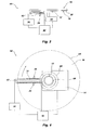
- an integrated optical disc label scanner system indicated generally at 10, in accordance with the present invention is shown.
- Home optical disc use is one example of a field that may benefit from use of such a system, for example.
- the system 10 provides a substrate 12 and a motor 14 for spinning an optical disc, shown generally at 16.
- the optical disc 16 can comprise any of a number of optical disc read only memory, writable, recordable, and rewritable formats including DVD, CD, CD-ROM, CD-R, CD-RW, and the like.
- a first surface 18 of the optical disc 16 can include a graphic display 20.
- the graphic display can be any type used in the graphic display arts, such as a silk-screened image, for example.
- the optical disc 16 can be positioned on the substrate 12 either in a face up or a face down orientation. In FIG. 1, the optical disc 16 is in a face down orientation.
- a track 22 Positioned to face a portion of the graphic display 20 on the first surface 18 is a track 22 for moving a sled 24 radially with respect to the optical disc 16.
- An emitting device 26 and a detecting device 28 are positioned on the sled 24 such that as the sled 24 moves radially with respect to the optical disc 16 along the track, and as the optical disc 16 spins, scanning of the graphic display 20 can occur spirally.
- the amount of time and the number of revolutions required to scan an entire graphic display 20 from an optical disc will depend on a few variables, including the amount of area the reflected energy will cover, dot-size, speed of the spinning disc, speed of the sled movement, and amount of energy overlap on the optical disc when spiral scanning, for example.
- the speed of the sled movement can optionally be varied to compensate for the length of optical disc 16 scanned per revolution near the outer boundary of the graphic display compared to the distance scanned per revolution near the inner boundary of the graphic display.
- the speed of the sled can increase.
- the sled 24 becomes further away from the center of the optical disc 16 its speed can decrease.
- the sled can move at a constant speed.
- a solenoid 34 can be used to effectuate movement of the sled 24 on the track 22.
- the emitting device can aim an energy beam 30 at the graphic display 20.
- the energy beam 30 can be, for example, a laser or other RF beam. If laser energy is used, then the emitting device 26 can be, for example, a laser device.
- the energy beam 30 can strike the graphic display 20 at a spot or region creating reflected energy 32, such as reflected laser energy.
- the reflected energy 32 will be more or less intense, or will undergo a wavelength shift with certain materials.
- the detecting device 28 can collect this information to be later processed.
- the emitting device can be aimed to reflect from the graphic display and substantially focus on the detecting device 28.
- the detecting device 28 can be, for example, a photo diode.
- the information collected by the photo diode can then be converted to voltage, current, or optical information, for example, which is proportional to the reflected energy.
- Examples of laser devices and photo diodes that can be used include those found in a typical CD, CD-ROM, or DVD player or device.
- the reflected energy 32 that is collected by the detecting device 28 can be converted to a reflected energy signal 36 to be processed by a signal processor 38.
- the signal processor 38 can be a PC, and can process the information by amplifying, filtering, or digitizing the reflected energy information, for example. Additionally, if the graphic display is collected spirally as described previously, the signal processor can be used to de-spiralize the image and put it together in a useful and recognizable condition. Additionally, the copy of the graphic display can be edited as is desired by the user.
- a power source/controller 40 can be present to provide power to and control of the signal processor 38, the emitting device 26, the solenoid 34, and the motor 14, for example.
- an alternative system can comprise an integrated optical disc label scanner system that can also simultaneously collect data from the data containing side of the optical disc.
- the optical disc 16 is shown in a standard orientation, with the graphic display 20 on the first surface 18 facing in an upward direction.
- a motor 14 and a substrate 12 are present for spinning and supporting the optical disc 16.
- two emitting devices and two detecting devices are present.
- a first emitting device 26a and a first detecting device 28a face the first surface 18 of the spinning optical disc 16 having the graphic display 20 thereon.
- a second emitting device 26b and a second detecting device 28b face a second surface 19 that contains the optical disc data.
- Each set of emitters and detectors are positioned on a first sled 24a and a second sled 24b, respectively. Additionally, the first sled 24a and the second sled 24b follow a first track 22a and a second track 22b, respectively.
- a single solenoid 34 is shown that acts to simultaneously cause both the first sled 24a and the second sled 24b to travel and collect information in unison. However, this is not required.
- each sled can be configured to be independent of the other. In such an embodiment, the use of two solenoids or other mechanical or electrical structures can be implemented for independent function.
- Both the graphic display 20 information collected from detecting device 28a and the data information collected from detecting device 28b can be sent to a processor via electrical or optical means.
- both signals can be fed to, for example, registers, common data buses, or industry standard interface 50 such as a USB, IDE, PCI, SERIAL, PARALLEL, SCSI, AGP, or other interfaces.
- the scanned graphic display can then be sent to a graphics signal processor 38 and the data collected can be sent to a data signal processor 52.
- Both can be a PC processor, for example.
- a power source is not shown, it is understood that a power source can be present, as in FIG. 1, to provide power to any system needing power.
- FIG. 3 and FIG. 4 an alternative embodiment of an integrated optical disc label scanner system 60 is shown.
- the optical disc 16, graphic display 20, first surface 18, optical disc substrate 12, and motor 14 are configured similarly as described with respect to FIG. 1.
- a plurality of emitting devices 26 are shown which are supported by an emitter/detector substrate 62.
- Detecting devices 28 are also present and are positioned on the emitter/detector substrate 62 to receive energy emitted from the emitting devices 26 and reflected from the graphic display 20 at or near a radial reflective region 70 of the optical disc 16.
- the radial reflective region 70 is fixed by the position of the emitter/detector substrate 62 and not by the optical disc 16, as the optical disc 16 is typically spinning on an axis while information is being collected from the graphic display 20.
- the emitter/detector substrate 62 can be configured to span a distance at least as great as a distance from an outer boundary 64 to an inner boundary 66 of the graphic display 20.
- a hole or void 68 is present that is used, in part, to interconnect the optical disc 16 to the substrate 12.
- a power source/controller 40 can be present to provide power to the emitting devices 26 and control the timing and intensity of individual emitting devices.
- a signal processor 38 can be coupled to detecting devices 28 to interpret the information collected therefrom. Further, the signal processor 38 and the power source/controller 40 can be interconnected to communicate with one another if desired.
- the emitted and detected energy can be configured such that each emitting device and detecting device provides a ring-shaped energy region on the spinning graphic display that overlaps or contacts another ring-shaped energy region of adjacent emitting and detecting devices.
- each emitting device and detecting device provides a ring-shaped energy region on the spinning graphic display that overlaps or contacts another ring-shaped energy region of adjacent emitting and detecting devices.
- a ring of scanned graphic information can be gathered.
- a series of ring shaped scanned images can be collected and pieced together, either by computer software or by human editing, creating a digitized copy of the entire scanned image.
- emitting devices and corresponding detecting devices can be energized one at a time, or can be energized two or more at a time. In one embodiment, by energizing all of the emitting devices simultaneously for one optical disc revolution, the entire image can be scanned.
- Color images can also be scanned by utilizing multiple photo detectors, each with a different color filter. If, for example, three color filters are used on three separate detecting devices, full color can be achieved. With such an embodiment, in may be desirable to use a white light laser or LED for the emitting device.
- a method of scanning a graphic display from an optical disc can comprise the steps of spinning an optical disc having a graphic display on a first surface; radiating progressive portions of the spinning first surface with a form of energy which interacts with sequential portions of the graphic display to capture in reflected energy a signal format of the graphic display; collecting the signal format of the graphic display while the optical disc is spinning; and converting the signal format of the graphic display into digitized data.
- the emitted energy can be any such energy that is functional with the present method, but particularly, can include laser energy, for example.
- the graphic display reflected energy can be collected or read by any of a number of sensors such as, for example, a photo diode.
- a method of copying a graphic display from a first optical disc to a second optical disc can comprise the steps of scanning a source graphic display from a first optical disc while the first optical disc is spinning; processing scanned information collected from the source graphic display; and printing a copy graphic display on a second optical disc wherein the copy graphic display is substantially similar to the source graphic display.
- the printing step can further comprise spinning the second optical disc and creating the copy graphic display on the second optical disc while it is spinning.
- the second optical disc can be printed upon by proxy, such as by printing on an adhesive label and adhering it to a non-data containing side of the optical disc.
Landscapes
- Optical Recording Or Reproduction (AREA)
- Optical Record Carriers And Manufacture Thereof (AREA)
- Image Input (AREA)
Abstract
Description
It is to be understood that the above-described arrangements are only illustrative of an application in accordance with principles of the present invention. Numerous modifications and alternative arrangements can be devised without departing from the spirit and scope of the present invention and the appended claims are intended to cover such modifications and arrangements. Thus, while the present invention has been shown in the drawings and fully described above with particularity and detail in connection with what is presently deemed to be the most practical and preferred embodiment(s) of the invention, it will be apparent to those of ordinary skill in the art that numerous modifications can be made without departing from the principles and concepts of the invention as set forth in the claims.
Claims (11)
- An integrated optical disc label scanner system, comprising:(a) a substrate configured for spinning an optical disc, said optical disc having a graphic display on a first surface;(b) an emitting device positioned near the substrate and configured for propagating energy for reflection from the graphic display; and(c) a detecting device positioned near the emitting device and configured to receive reflected energy sourced from the emitting device and reflected from the graphic display while the optical disc is spinning.
- An integrated optical disc label scanner system as in claim 1, further comprising a signal processor coupled to the detecting device and configured for converting the energy collected by the detecting device into digitized data corresponding to the graphic display.
- An integrated optical disc label scanner system as in claim 1 further comprising a track for radially moving the emitting device and the detecting device with respect to the optical disc.
- An integrated optical disc label scanner system as in claim 2, wherein the digitized data corresponds to a spiral path of the graphic display on the first surface of the optical disc.
- An integrated optical disc label scanner system, comprising:(a) a substrate configured for spinning an optical disc, said optical disc having a graphic display on a first surface, said graphic display defined by an outer boundary and an inner boundary;(b) an emitting device positioned near the substrate and configured for propagating energy for reflection from the graphic display along a radial axis from the outer boundary to the inner boundary; and(c) a detecting device positioned near the emitting device and configured to receive reflected energy sourced from the emitting device and reflected from the graphic display while the optical disc is spinning, said detecting device configured along the radial axis from the outer boundary to the inner boundary such that the graphic display can be detected in sectional rings.
- An integrated optical disc label scanner system as in claim 1, further comprising a signal processor coupled to the detecting device and configured for converting the energy collected by the detecting device into digitized data corresponding to the graphic display.
- An integrated optical disc label scanner system as in claim 2 or 6, wherein the digitized data comprises information that is printable and wherein said printable information is substantially similar to the graphic display on the first surface of the optical disc.
- A method of scanning a graphic display from an optical disc, comprising:(a) spinning an optical disc having a graphic display on a first surface;(b) radiating progressive portions of the spinning first surface with a form of energy which interacts with sequential portions of the graphic display to capture in reflected energy a signal format of the graphic display;(c) collecting the signal format of the graphic display while the optical disc is spinning; and(d) converting the signal format of the graphic display into digitized data.
- A method as in claim 8, wherein the emitted energy is laser energy and the reflected energy is collected with a photo diode.
- A method of copying a graphic display from a first optical disc to a second optical disc, comprising:(a) scanning a source graphic display from a first optical disc while the first optical disc is spinning;(b) processing data collected from the source graphic display; and(c) printing a copy graphic display on a second optical disc wherein the copy graphic display is substantially similar to the source graphic display.
- A method as in claim 10, wherein the printing step further comprises spinning the second optical disc and printing the copy graphic display while the second optical disc is spinning.
Applications Claiming Priority (2)
| Application Number | Priority Date | Filing Date | Title |
|---|---|---|---|
| US59610 | 2002-01-28 | ||
| US10/059,610 US6801487B2 (en) | 2002-01-28 | 2002-01-28 | Integrated optical disc label scanner system and method of scanning an optical disc graphic display |
Publications (2)
| Publication Number | Publication Date |
|---|---|
| EP1331641A2 true EP1331641A2 (en) | 2003-07-30 |
| EP1331641A3 EP1331641A3 (en) | 2005-11-09 |
Family
ID=22024078
Family Applications (1)
| Application Number | Title | Priority Date | Filing Date |
|---|---|---|---|
| EP03250203A Withdrawn EP1331641A3 (en) | 2002-01-28 | 2003-01-14 | Integrated optical disc label scanner system and method of scanning an optical disc graphic display |
Country Status (3)
| Country | Link |
|---|---|
| US (1) | US6801487B2 (en) |
| EP (1) | EP1331641A3 (en) |
| JP (1) | JP2003228955A (en) |
Cited By (2)
| Publication number | Priority date | Publication date | Assignee | Title |
|---|---|---|---|---|
| EP1936609A2 (en) | 2006-12-19 | 2008-06-25 | Yamaha Corporation | Image reader |
| US7965613B2 (en) | 2006-12-19 | 2011-06-21 | Yamaha Corporation | Image reader |
Families Citing this family (11)
| Publication number | Priority date | Publication date | Assignee | Title |
|---|---|---|---|---|
| US7187637B2 (en) * | 2002-04-15 | 2007-03-06 | Hewlett-Packard Development Company, L.P. | Opto-mechanical adjustment based on sensing label side of optical disc |
| US7733754B2 (en) * | 2004-09-07 | 2010-06-08 | Dell Products L.P. | System and method for disc labeling |
| US7159776B2 (en) * | 2005-01-05 | 2007-01-09 | Dell Products L.P. | System and method for optical medium label alignment |
| JP4548144B2 (en) * | 2005-02-23 | 2010-09-22 | カシオ計算機株式会社 | Digital camera device and through image display method |
| US7687550B2 (en) * | 2005-10-24 | 2010-03-30 | Hewlett-Packard Development Company, L.P. | Composition including a radiation-curable pre-polymer with a stabilizing additive comprising metal particles |
| US7801004B2 (en) * | 2005-10-31 | 2010-09-21 | Hewlett-Packard Development Company, L.P. | Method of error correction for a series of marks on an optical disc |
| JP4651102B2 (en) * | 2005-11-16 | 2011-03-16 | キヤノン株式会社 | Print control apparatus, print control method, and program |
| US7890968B2 (en) * | 2007-01-26 | 2011-02-15 | Hewlett-Packard Development Company, L.P. | Optical disc device having two optomechanical mechanisms |
| US20080261808A1 (en) * | 2007-04-23 | 2008-10-23 | Hewlett-Packard Development Company, L.P. | Recordable medium with template pattern |
| US8547817B2 (en) * | 2007-09-28 | 2013-10-01 | Hewlett-Packard Development Company, L.P. | Methods and apparatus for merging pre-rendered and dynamic optical-storage label indicia |
| US20120033537A1 (en) * | 2010-08-06 | 2012-02-09 | Rimage Corporation | Copy station |
Family Cites Families (7)
| Publication number | Priority date | Publication date | Assignee | Title |
|---|---|---|---|---|
| DE4123758A1 (en) * | 1991-07-18 | 1993-01-21 | Telefunken Fernseh & Rundfunk | Playback programming system for CD player |
| US5589952A (en) * | 1994-03-18 | 1996-12-31 | Sony/Tektronix Corporation | Disc high resolution scanner |
| DE69614823T2 (en) * | 1995-10-09 | 2002-04-11 | Matsushita Electric Industrial Co., Ltd. | RECORDING DEVICE FOR OPTICAL DISKS |
| JP3341572B2 (en) * | 1996-03-27 | 2002-11-05 | セイコーエプソン株式会社 | Optical disk drive |
| US6122042A (en) * | 1997-02-07 | 2000-09-19 | Wunderman; Irwin | Devices and methods for optically identifying characteristics of material objects |
| US5988513A (en) * | 1997-03-28 | 1999-11-23 | Dean; Robert | Re-writable display device and system including a carrier having humanly legible characters and an indexing track |
| US5967676A (en) | 1998-03-31 | 1999-10-19 | Microtech Conversion Systems, Inc. | Image orientation system for disk printing |
-
2002
- 2002-01-28 US US10/059,610 patent/US6801487B2/en not_active Expired - Fee Related
-
2003
- 2003-01-09 JP JP2003003615A patent/JP2003228955A/en not_active Withdrawn
- 2003-01-14 EP EP03250203A patent/EP1331641A3/en not_active Withdrawn
Cited By (3)
| Publication number | Priority date | Publication date | Assignee | Title |
|---|---|---|---|---|
| EP1936609A2 (en) | 2006-12-19 | 2008-06-25 | Yamaha Corporation | Image reader |
| EP1936609A3 (en) * | 2006-12-19 | 2009-03-04 | Yamaha Corporation | Image reader |
| US7965613B2 (en) | 2006-12-19 | 2011-06-21 | Yamaha Corporation | Image reader |
Also Published As
| Publication number | Publication date |
|---|---|
| US6801487B2 (en) | 2004-10-05 |
| EP1331641A3 (en) | 2005-11-09 |
| US20030142613A1 (en) | 2003-07-31 |
| JP2003228955A (en) | 2003-08-15 |
Similar Documents
| Publication | Publication Date | Title |
|---|---|---|
| US6801487B2 (en) | Integrated optical disc label scanner system and method of scanning an optical disc graphic display | |
| US7676119B2 (en) | Method and system for using an optical sensor array to control a labeling device | |
| EP0054438A1 (en) | Optical disk having an index mark | |
| JPH05303868A (en) | Photo-compact disk capable of marking recording picture quality and method and device for using the same | |
| JP4003691B2 (en) | Visible image forming method, program, and visible image forming system | |
| CN100351918C (en) | Method of forming visual image on optical disk by laser beam | |
| US7349297B2 (en) | Method and apparatus for acquiring an index mark | |
| JP2006514399A (en) | Optical disc improved for speed and orientation tracking | |
| HK1056039A (en) | Integrated optical disc label scanner system and method of scanning an optical disc graphic display | |
| US6866354B2 (en) | Disk shape determining and labeling system | |
| EP0523334B1 (en) | Optical information recording medium and reproducing apparatus for reproducing information from the medium | |
| JPS63251938A (en) | Optical information recording and reproducing device | |
| JP2006511034A (en) | Optical disk drive | |
| EP2276026A1 (en) | Preventing unauthorized use of optical discs | |
| TWI263038B (en) | Inspection system and inspection method | |
| US5523995A (en) | Optical information read/write system with a spread plane beam | |
| JPH0756726B2 (en) | Rotation synchronization mark detector | |
| EP0668588B1 (en) | Recorded signal detection apparatus | |
| JP4817127B2 (en) | Optical pickup device | |
| US20030128642A1 (en) | Optical disk, optical disk recording and reproducing device, and methodof recording in optical disk | |
| JPH0636512A (en) | Optical disk and information control system thereof | |
| JP2004055039A (en) | Recording medium, and recorded medium reproducing device | |
| JP2008152630A (en) | Image reader | |
| JP2006209855A (en) | Optical disk device | |
| JP2004005843A (en) | Recording medium and playback device |
Legal Events
| Date | Code | Title | Description |
|---|---|---|---|
| PUAI | Public reference made under article 153(3) epc to a published international application that has entered the european phase |
Free format text: ORIGINAL CODE: 0009012 |
|
| AK | Designated contracting states |
Designated state(s): AT BE BG CH CY CZ DE DK EE ES FI FR GB GR HU IE IT LI LU MC NL PT SE SI SK TR |
|
| AX | Request for extension of the european patent |
Extension state: AL LT LV MK RO |
|
| PUAL | Search report despatched |
Free format text: ORIGINAL CODE: 0009013 |
|
| AK | Designated contracting states |
Kind code of ref document: A3 Designated state(s): AT BE BG CH CY CZ DE DK EE ES FI FR GB GR HU IE IT LI LU MC NL PT SE SI SK TR |
|
| AX | Request for extension of the european patent |
Extension state: AL LT LV MK RO |
|
| 17P | Request for examination filed |
Effective date: 20060424 |
|
| AKX | Designation fees paid |
Designated state(s): DE FR GB NL |
|
| STAA | Information on the status of an ep patent application or granted ep patent |
Free format text: STATUS: THE APPLICATION HAS BEEN WITHDRAWN |
|
| 18W | Application withdrawn |
Effective date: 20061227 |
|
| REG | Reference to a national code |
Ref country code: HK Ref legal event code: WD Ref document number: 1056039 Country of ref document: HK |