FIELD OF THE INVENTION
-
The invention herein generally relates to the field of imaging
systems for use in the graphic arts industry. Further, the invention
more specifically relates to reducing perceivable artifacts from
being formed in printed images.
BACKGROUND OF THE INVENTION
-
Color images are often printed using four colors (more or less
colors are also known), yellow, cyan, magenta, and black. For each
color used on a printing press, a different printing plate is used.
If a four color printing press is used to produce a color image,
then as many as four printing plates are needed to produce the color
image. Each printing plate designated for a different color, and to
be used together to print a particular image (the same print job)
has the same or a similar image placed upon each plate as is well
known in the art.
-
Platesetters are machines used to transfer an electronic image
onto a printing plate, for subsequent use on a printing press.
Platesetters often use laser based imaging systems to transfer an
electronic image onto the plate, in a process called imaging. A
typical laser imaging system employs many individual laser beams to
image a printing plate. The plurality of laser beams used to image a
plate, sometimes called writing beams, or just beams, often emanate
from a moveable assembly referred to as an imaging head. An example
of a multi-beam imaging head for an external drum platesetter is
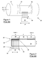
shown in figure 1. The optic energy produced by the laser (or
lasers) is utilized to transfer an electronic image onto a printing
plate that is photosensitive or thermally sensitive (including
ablative) as is well known in the art.
-
Color images printed using a printing press such as a
lithographic printing press are verified for quality prior to, and
during printing. A measure of the quality of a printed color image
is the presence or absence of artifacts in the image. Artifacts are
undesired variations in the printed image, such as the well known
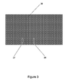
banding phenomenon shown in figure 3. Many causes contribute to
generation of artifacts in a printed image. Periodic artifacts, such
as banding may be caused by repetitive equipment errors in the
printing press itself, or in the equipment used during the pre-printing
press phase of production, called prepress. Platesetters
are an example of prepress equipment.
-
Image processing is often employed to compensate for equipment
errors in an effort to remove artifacts from an image, or
alternatively, to prevent artifacts from being formed in the image.
United States Patent number 6,185,002 to Askeland et al is one
example of where image data is manipulated to reduce artifacts such
as banding. This intensive data manipulation carries a significant
cost in terms of required computing power, memory, and additional
software. This data manipulation step, or steps, serves to increase
costs and reduce throughput in addition to changing the image via
adding or deleting image pixels.
-
What is needed is a means to reduce or eliminate artifacts in a
printed image without having to resort to expensive image processing
methods that increase cost.
-
Further, it is also desirable to be able to reduce or eliminate
artifacts without adding additional hardware to existing equipment.
SUMMARY OF THE INVENTION
-
The above-mentioned advantageous effects are realised by a
method having the specific features set out in claim 1 and by a
system having the specific features set out in claim 6. Specific
features for preferred embodiments are set out in the dependent
claims.
-
The invention herein solves the problems described supra and
others, by using a different starting beam of a multi-beam imaging
head when imaging each printing plate designated for a unique color
plane, subsequently used to print a given image.
-
The method according to the invention may be applied in a
platesetter, an imagesetter, an ink jet system having a plurality of
nozzles for each color component etc.
-
In a platesetter, each image component is preferably formed on a
printing plate, by imaging pixels, e.g. image-wise exposure of
specific locations of the printing plate, by a plurality of imaging
beams, generated by a plurality of imaging elements or image beam
generators of a multi-beam imaging head. A composite image may then
be formed by mounting on a multi-color printing press a plurality of
printing plates, each having an image component. Ink from imaged
pixels of a first printing plate is then deposited on a substrate
and overprinted by ink from spatially corresponding imaged pixels of
a second printing plate, and optionally by ink from a third, fourth,
etc. printing plate. A first pixel of a first image component is
spatially corresponding to a second pixel of second image component,
if the first and second pixel both relate to one specific location
of the original image or composite image. Each printing plate is
preferably imaged using one imaging head. However, according to the
invention a first pixel and its spatially corresponding second pixel
may be imaged or exposed by two different imaging beams or image
beam generators of the imaging head.
-
In an inkjet system, the method may use a plurality of print heads,
each one for a specific color. Each print head may have a plurality
of ink nozzles for operating as imaging elements. The first nozzle
of the first print head may be structurally corresponding to the
first nozzle of the second print head. The second nozzle of the
first print head is then structurally corresponding to the second
nozzle of the second print head, etc. and preferably, the last
nozzle of the first print head is structurally corresponding to the
last nozzle of the second print head. The step of combining the
first image component with the second image component may happen
even before the first image component is fully printed on the
substrate. According to the invention, a first pixel imaged by the
first nozzle of the first print head may be combined with a second
pixel imaged by a second or third, etc. nozzle, but not the first
nozzle of the second print head.
-
Further advantages and embodiments of the present invention will
become apparent from the following description and drawings.
BRIEF DESCRIPTION OF THE DRAWINGS
-
The following description may be further understood with
reference to the accompanying drawings in which:
- Figure 1 is a schematic of a multi-beam imaging machine for imaging
printing plates.
- Figure 2 is prior art showing how a printing plate is imaged.
- Figure 3 is an example of an artifact referred to as banding.
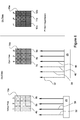
- Figure 4 demonstrates how multiple pixels (or dots) can be used to
create a color image.
- Figure 5 shows one mechanism causing banding.
- Figure 6 shows how the invention herein reduces banding at the pixel
level.
- Figure 7 shows how the invention herein is implemented on a
platesetter.
- Figure 8 is the example of the banding artifact shown in figure 3
reproduced adjacent other figures to facilitate comparison with
figure 9.
- Figure 9 is the sample image of figure 8 showing the utility of the
invention herein by removing (or preventing) the banding artifact
(from being formed).
- Figure 10 shows alternate embodiments of the invention.
-
-
The drawings are shown for illustrative purposes only,
and are not to scale.
DETAILED DESCRIPTION OF THE INVENTION
-
Though the following description of the invention herein is
described in the context of an external drum platesetter, the
application of the invention should not be limited to such. For
example, the invention herein may also be employed on internal drum
or flatbed platesetters, external or internal drum imagesetters
and/or printing presses. Printing plate 23 may alternatively be a
piece of film in lieu of a printing plate without deviating from the
scope of the invention. Further, the invention herein may be
practiced with all types of printing plates, including but not
limited to, aluminum, polyester, flexographic etc..
-
Referring to figure 1, printing plate 23 is mounted on an
external drum 21 of a platesetter 20. Plate 23 has an imageable area
24 that an image (not shown) is transferred onto using moveable
imaging apparatus 25, often referred to as an imaging head. Drum 21
is rotatable as shown by arrow 22, which in conjunction with
moveable imaging head 25, the movement thereof shown by arrow 27,
operates to move a plurality of N imaging beams 26 over the entire
imageable area 24 of plate 23. The number N, of imaging beams
provided by multi-beam imaging head 25 is not restricted. Imaging
heads having 96 beams, or as many as 1088 beams are known.
-
Referring to figure 2, imageable area 24 can be viewed as
consisting of many individual picture elements, or pixels, that must
be imaged, or "turned on". Though only a single row of pixels 28 are
shown in figure 2, it is understood that the entire imageable area
24 consists of pixels. Imaging head 25 is shown having a plurality
of imaging beams 26 aligned with the row of pixels 28. The alignment
is such that the first beam 32 of N beams is aligned with the first
pixel 33 in the row of pixels 28. An N beam imaging head can image a
swath 29 having a width of N pixels. From this initial starting
position, an image is transferred (imaged) onto plate 23. The first
beam used to image the first pixel 33 in this example is beam 32,
and is referred to as the starting beam. The starting beam as
defined in this application, is the first beam, of a multi-beam
imaging head, that is used to start imaging the first pixel of an
image to be placed on imageable area 24. In accordance with the
invention herein, the starting beam may be a beam other than the
first beam in a multi-beam array.
-
The plurality of beams 26 are moved down plate 23 due to
rotation of the drum 21 forming a swath 29 on imageable area 24.
Note that though the swaths herein are described as vertical, or
parallel to an edge of plate 23, the swaths may also be helical due
to the combined rotational movement of drum 21 and lateral movement
of imaging head 25. After swath 29 has been imaged, imaging head 25
is positioned to image the next swath 30, and imaging is continued
in this manner until the entire electronic image is placed on
imageable area 24, the last swath being swath 31. Although three
swaths are described, the number of swaths may be any number, and is
dependent upon the size of the plate and number of imaging beams
among other variables. The total number of swaths is independent of
the invention herein.
-
Once plate 23 has been imaged, it may be further processed
(e.g. developed) if required depending upon the type of plate before
being used on a printing press. Plate 23 is designated for use with
only one color of ink, called a color plane, and is used on a
printing press. Consequently, an additional printing plate must also
be imaged with the same or similar image for each primary color used
in the subsequent printing process for a given print job as is well
known in the art. An image placed on a printing plate, designated
for a particular color, may not be identical to an image placed on a
printing plate designated for a different color plane as is well
known in the art. A printing plate designated for use with a
particular color on a printing press is referred to as that
particular color plate to avoid confusion with other plates. For
example, a plate designated for use with the color yellow, is called
a yellow plate even though the plate is not actually yellow in
color.
-
When a color image is printed using multiple plates for the
different colors as is known in the art, artifacts may be created.
-
Some types of artifacts may appear as a white line (or other
color) in a color field or variations in intensity of a color field
or fields. The color fields in which artifacts may appear are not
limited to the primary color fields such as cyan, yellow, magenta
(reddish) and black. Composite color fields may also be affected
such as green. A green color field is created on a printing press by
placing a yellow dot on a substrate with one printing plate, and
then placing a cyan (a bluish color) dot on top of the yellow dot
using a different printing plate. The two colors (composed of ink,
wax etc.) mix yielding green.
-
Referring to figure 4, the process can be visualized. A portion
of a yellow printing plate 13 is shown consisting of nine pixels
arranged in three columns 1, 2, and 3, of three pixels each. A
printer's "dot" or halftone dot is composed of a plurality of
pixels. The number of pixels per dot is dependent upon the various
resolutions required or used (e.g. dpi, number of line
screens, spatial frequency of the halftone dots or line frequency
etc.) for a given type of printing technology and may or may not be
in the range of 20-64 pixels per printers dot. Pixels (or microdots)
are typically imaged on a printing plate using a platesetter, and
dots (or halftone dots) are typically printed on a substrate (e.g.
paper, cardboard, bumper sticker, cloth etc.) using a printing
press. Again referring to figure 4, a portion of a cyan printing
plate 14 is shown consisting of nine pixels arranged in three
columns 1', 2', and 3', of three pixels each. After plates 13 and 14
are imaged in the prepress phase of production, the plates are
installed onto a printing press (not shown). Plate 13 is used to
place yellow ink onto substrate 15 in the nine-pixel pattern shown.
Plate 14 is then used to place cyan ink onto substrate 15, on top of
the yellow nine-pixel pattern, also in the same nine-pixel pattern
shown. The resulting nine-pixel pattern on substrate 15 has a green
color. Though the figures are black and white, the additive effect
is similar in that the gray color of substrate 15 is darker than
either plate 13 or 14 and represents the result of adding yellow and
cyan for illustrative purposes only.
-
Referring to figure 5, one mechanism that creates artifacts
will be shown. The type of artifact to be shown is banding which can
be a variation in color intensity, but well may be another type.
Each column of pixels shown in figures 4-6 corresponds to a unique,
single imaging beam emanating from N beam imaging head 25. For this
example, in figure 5, the first three beams of multi-beam imaging
head 25 are used to image pixel columns 1,2, and 3. Also, for this
example, we assume the second beam has very low optic power output
such that pixels imaged by the second beam are not "fully imaged"
resulting in a light color being produced when the plate is used for
printing. This is shown on plate 13a by the columns of imaged pixels
4a and 6a being darker than column 5a. Since the same physical
imaging beams, the first three beams in this example, are used to
image all color plates, the same problem also exists on the cyan
plate 14a as shown by imaged pixel columns 7a and 9a being darker
than 8a. The net result is that when plates 13a and 14a are used to
print the image on substrate 15a, column 11a of figure 5 is a much
lighter green than columns 10a and 12a. This phenomenon occurs at
the pixel level on printing plates 13a and 14a, and appears as a
series of alternating light and dark bands 37, 38 across the printed
image 36 as shown in figure 3.
-
A solution to this problem herein is demonstrated in figures 6
and 7. When imaging plate 13a (designated for use with the color
yellow on press) is imaged, the starting beam in this example is
actually the second beam 39 of multi-beam imaging head 25. This is
seen in figure 6 because beam 39 is aligned with the first column of
pixels 1 on plate 13a. Figure 6 shows imaged pixel column 5b being
lighter in color than imaged pixel columns 4b and 6b similar to the
previous example. However, different from the previous example, the
starting beam for cyan plate 14a is actually the fourth beam 48 of
multi-beam imaging head 25. Since, in this example, the fourth beam
48 has normal optic power output, imaged pixel column 8b has the
same color intensity as adjacent imaged pixel columns 7b and 9b.
Note that the starting beams for yellow plate 13a and cyan plate 14a
are not the same, therefore a different set of imaging beams are
used to image each color plate. This dilutes the effect of any
imaging beam of multi-beam imaging head 25 that may be low in optic
power or may be out of focus or have other spatial errors. The
result of this method is that the color field created on substrate
15a by a printing press using plates 13a and 14a is much more
uniform as shown in figure 6. Printed color column 11b is much
closer in color intensity to adjacent printed color columns 10b and
12b, than printed color column 11a is to columns 10a and 12a in
figure 5.
-
In a preferred embodiment, a different start beam is used for
each printing plate that is designated for use with a unique color
plane when used on a printing press for a particular print job. In
other words, if a print job (e.g. a magazine cover) requires four
colors on press, then the four required printing plates
(corresponding to the four required colors) are imaged on an imaging
machine using a different starting beam for each plate. The sequence
that the starting beams are selected from plate to plate, may be
random, pseudo-random, fixed offset, or even sequential. For
example, if four plates are required (e.g. designated for yellow,
cyan, magenta, and black) the starting beams could be 1, 13, 21, and
4 respectively. In a preferred embodiment, a random beam selection
process is utilized
-
Referring to figure 7, the invention herein is shown compared
to the previous technique of using the first beam 32 as the starting
beam and using all available beams for all plates. The starting beam
40 is actually the third imaging beam of N beams in multi-beam
imaging head 25. This means that the first two beams 32, 39 are not
used to image this particular plate. In a preferred embodiment, the
first two beams 32, 39 are not used to image only the first swath
44, and all N beams are used to image the remaining swaths (except
for residual swath 47). Since a subset of the full number of N beams
is used to image at least some of the plates, some pixels 42 remain
that would otherwise have been imaged if the full number of N beams
were utilized. Consequently, at least one additional swath 47 may be
required to fully image the imageable area 24 of plate 23. Using the
technique herein, swaths 44-47 are required versus swaths 29-31 to
image the same imageable area 24. Each color printing plate, each of
which is imaged using a different starting beam (or different set of
beams) may each require a different number of swaths in order to
fully image each plate.
-
Figure 3 is reproduced as figure 8 to facilitate comparison
with figure 9, showing the effect of implementing the invention
herein. Figure 8 clearly shows the banding phenomenon on what is
otherwise a uniform color image. Alternating bands of light 37 and
dark 38 color intensity are seen in the image 36 of figure 8 and are
absent in the image 36a of figure 9. Figures 8 and 9 are macro
(whole image) representations of the micro representations (pixel
level of image) shown in figures 4-6. Even though some banding may
still remain after implementing the method of the invention herein,
the residual banding is virtually undetectable to the human eye. The
banding has essentially been obscured or hidden and is simply not
perceivable to the unaided eye.
-
In a first alternate embodiment, the ending beam may be varied
and the starting beam may be the same for each color plate. For
example, referring to figure 10, starting beam 32 is used to image
the first pixel 33 on each color plate (the imageable area 24 for
only one plate is shown for clarity). However, the ending beam will
be different for each color plate. One implementation of this
alternate embodiment could be beams 1 to N are used to image a
yellow plate, beams 1 to (N-1) used to image a cyan plate, beams 1
to (N-2) used to image a magenta plate, and beams 1 to (N-3) used to
image a black plate. This is illustrated in figure 10 by beams 34,
35, and 41 shown as dotted lines indicating that one or more of
beams 34, 35, or 41 is not used to image some of the plates.
-
A result of the first alternate embodiment is the first swath
of the printed image will still have banding since the same beams
are used to image equivalent pixels on all the plates. However, the
remaining portion of the printed image will have the banding removed
(or obscured). Since a single swath is actually a very small portion
of the total printed image, the banding in the first swath may not
be prominent.
-
A second alternate embodiment uses different starting and
ending beams for each color plate. However, the printed image will
still have banding which may be acceptable in some print runs.
-
The previously described embodiments are variable swath
techniques on a plate to plate basis. A third alternate embodiment
is to use any of the previously described embodiments, wherein a
given color plate (e.g. the yellow plate) has the starting beam,
ending beam, or both starting and ending beams varied on a swath to
swath basis within the same plate. The result would be some residual
banding may remain, which may be acceptable depending on the
particular print run.
-
Though the invention herein has been described for use with
printing systems that use printing plates, the invention is not
limited to such. The invention herein may also be adapted for use
with color printers that do not use printing plates, but use
separate color cartridges, such as inkjet printers, laser printers
or any multi-beam scanning system.
-
Further, the invention is also suitable for use with on-press
plate making systems (alternatively referred to as plateless
printing systems) where temporary printing plates are actually
created on a cylinder (or other support surface).
-
Those skilled in the art will appreciate that numerous
modifications and variations may be made to the above disclosed
embodiments without departing from the scope of the present
invention.