EP1330984A1 - Diagnostic device, ultrasonic diagnostic device, and their operation control method - Google Patents
Diagnostic device, ultrasonic diagnostic device, and their operation control method Download PDFInfo
- Publication number
- EP1330984A1 EP1330984A1 EP01974761A EP01974761A EP1330984A1 EP 1330984 A1 EP1330984 A1 EP 1330984A1 EP 01974761 A EP01974761 A EP 01974761A EP 01974761 A EP01974761 A EP 01974761A EP 1330984 A1 EP1330984 A1 EP 1330984A1
- Authority
- EP
- European Patent Office
- Prior art keywords
- frequency
- group
- predetermined
- operational condition
- parameter value
- Prior art date
- Legal status (The legal status is an assumption and is not a legal conclusion. Google has not performed a legal analysis and makes no representation as to the accuracy of the status listed.)
- Granted
Links
Images






Classifications
-
- A—HUMAN NECESSITIES
- A61—MEDICAL OR VETERINARY SCIENCE; HYGIENE
- A61B—DIAGNOSIS; SURGERY; IDENTIFICATION
- A61B8/00—Diagnosis using ultrasonic, sonic or infrasonic waves
- A61B8/58—Testing, adjusting or calibrating the diagnostic device
- A61B8/585—Automatic set-up of the device
-
- A—HUMAN NECESSITIES
- A61—MEDICAL OR VETERINARY SCIENCE; HYGIENE
- A61B—DIAGNOSIS; SURGERY; IDENTIFICATION
- A61B8/00—Diagnosis using ultrasonic, sonic or infrasonic waves
Definitions
- the present invention relates to a diagnostic apparatus and an ultrasonic diagnostic apparatus used for diagnosis, and the controlling method thereof.
- an ultrasonic diagnostic apparatus using ultrasound As a diagnostic apparatus for examining the body of an object, there are an ultrasonic diagnostic apparatus using ultrasound, an X-ray CT scanner using X-ray, and a magnetic resonance imaging apparatus using magnetic force.
- various setting including the setting of frequency to be used and imaging region are required, when making a diagnosis.
- a color angiography for displaying the blood signal in color has become prevalent in the ultrasonic apparatus, a helical scan method of scanning spirally becomes prevalent in the X-ray CT scanner, and a lot of pulse sequences for applying magnetic fields are used in the nuclear magnetic resonance imaging apparatus. Therefore, setting condition in using the respective diagnostic devices are likely to be increased.
- the ultrasonic diagnostic apparatus can be used for diagnosis of every region because of having no ill effect of exposure to radiation. Owing to this characteristic, various conditions depending on the regions to be diagnosed must be set. When taking the frequency that is one of the conditions, as an example, generally, different frequencies must be set in the examination of the abdominal region and in the examination of a fetus. Further, in many cases, various frequencies may be used according to the operator's taste or the state of a patient. Moreover, different frequencies may be used according to the display method of B mode or color mode.
- the ultrasonic diagnostic apparatus of a compact size can make a quick diagnosis, it is very useful as the emergency diagnostic apparatus and therefore, a quick setting of conditions is strongly desired in the ultrasonic diagnostic apparatus.
- the invention is to provide a diagnostic apparatus setting method and setting means capable of setting an apparatus quickly and a diagnostic apparatus using the above method and means.
- the invention implements the following means, in order to achieve the above objects.
- a first aspect of the invention is an ultrasonic diagnosis apparatus comprising: an input unit for selecting at least one frequency from a plurality of frequencies of ultrasonic pulse transmitted from an ultrasonic probe; a storing unit for storing at least the one frequency selected by the input unit as a frequency group; and a driving signal generator for generating a driving signal for driving the ultrasonic probe at the predetermined frequency specified when the input unit specifies a predetermined frequency from at least the one frequency forming the frequency group being stored.
- a second aspect of the invention is an ultrasonic diagnostic apparatus comprising: a storing unit for storing a plurality of frequency groups each consisting of at least one frequency of a plurality of frequencies of ultrasonic pulse transmitted from an ultrasonic probe; an input unit for specifying a predetermined frequency group from the frequency groups and specifying a predetermined frequency from at least the one frequency forming the predetermined frequency group; and a driving signal generator for generating a driving signal for driving the ultrasonic probe at the predetermined frequency specified by the input unit.
- a third aspect of the invention is an ultrasonic diagnosis apparatus comprising: an input unit for selecting two and more frequencies from a plurality of frequencies of ultrasonic pulse transmitted from an ultrasonic probe and specifying order of priority; a storing unit for storing the two and more frequencies selected by the input unit, together with the priority order, as a frequency group; and a driving signal generator for generating a driving signal for driving the ultrasonic probe at the two and more frequencies forming the frequency group, according to the priority order, when the input unit specifies the frequency group being stored.
- a fourth aspect of the invention is an ultrasonic diagnosis apparatus comprising: an input unit for selecting at least one parameter value as for a parameter as an operational condition of the apparatus; a storing unit for storing at least the one parameter value selected by the input unit as an operational condition group; and a controlling unit for generating a signal for controlling the apparatus at the predetermined parameter value specified when the input unit specifies a predetermined parameter value from at least the one parameter value forming the operational condition group being stored.
- a fifth aspect of the invention is an ultrasonic diagnostic apparatus comprising: a storing unit for storing a plurality of operational condition groups each consisting of at least one parameter value as for a predetermined parameter as an operational condition of the apparatus, an input unit for specifying a predetermined operational condition group from the operational condition groups and specifying a predetermined parameter value from at least the one parameter value forming the predetermined operational condition group; and a controlling unit for generating a signal for controlling the apparatus at the predetermined parameter value specified by the input unit.
- a sixth aspect of the invention is an ultrasonic diagnosis apparatus comprising: an input unit for specifying at least one combination set of parameter values as for an operation condition of the apparatus defined by a combination of at least two or more kinds of parameters; a storing unit for storing at least the one combination set of parameter values specified by the input unit as an operational condition group; and a controlling unit for generating a signal for controlling the apparatus according to the predetermined combination of parameter values specified, when the input unit specifies a predetermined combination of parameter values from at least the one combination set of parameter values forming the operational condition group being stored.
- a seventh aspect of the invention is an ultrasonic diagnostic apparatus comprising: a storing unit for storing a plurality of operational condition groups each consisting of at least one combination set of parameter values as for an operational condition of the apparatus defined by a combination of at least two or more kinds of parameters; an input unit for specifying a predetermined operational condition group from the operational condition groups and specifying a predetermined combination of parameter values from at least the one combination set of parameter values forming the predetermined operational condition group; and a controlling unit for generating a signal for controlling the apparatus in the predetermined combination of parameter values specified by the input unit.
- An eighth aspect of the invention is a diagnosis apparatus comprising: an input unit for selecting at least one parameter value as for a parameter as an operational condition of the apparatus; a storing unit for storing at least the one parameter value selected by the input unit as an operational condition group; and a controlling unit for generating a signal for controlling the apparatus at the predetermined parameter value specified when the input unit specifies a predetermined parameter value from at least the one parameter value forming the stored operational condition group.
- a ninth aspect of the invention is a diagnostic apparatus comprising: a storing unit for storing a plurality of operational condition groups each consisting of at least one parameter value as for a parameter as an operational condition of the apparatus; an input unit for specifying a predetermined operational condition group from the operational condition groups and specifying a predetermined parameter value from at least the one parameter value forming the predetermined operational condition group; and a controlling unit for generating a signal for controlling the apparatus at the predetermined parameter value specified by the input unit.
- a tenth aspect of the invention is an operation controlling method of an ultrasonic diagnosis apparatus, comprising: a step of selecting at least one frequency from a plurality of frequencies of ultrasonic pulse transmitted from an ultrasonic probe; a step of registering at least the one frequency selected by the input unit as a frequency group; a step of specifying a predetermined frequency from at least the one frequency forming the frequency group being registered; and a step of driving the ultrasonic probe at the specified predetermined frequency.
- An eleventh aspect of the invention is an operation controlling method of an ultrasonic diagnostic apparatus, comprising: a step of specifying a predetermined frequency group from a plurality of frequency groups each consisting of at least one frequency of a plurality of frequencies of ultrasonic pulse transmitted from an ultrasonic probe; a step of specifying a predetermined frequency from at least the one frequency forming the predetermined frequency group; and a step of driving the ultrasonic probe at the specified predetermined frequency.
- a twelfth aspect of the invention is an operation controlling method of a diagnosis apparatus, comprising: a step of selecting at least one parameter value as for a parameter as an operational condition of the apparatus; a step of storing at least the one parameter value selected above, as an operational condition group; a step of specifying a predetermined parameter value from at least the one parameter value forming the operational condition group being stored, by the input unit; and a step of controlling the apparatus at the specified predetermined parameter value.
- a thirteenth aspect of the invention is an operation controlling method of a diagnosis apparatus, comprising: a step of specifying a predetermined operational condition group from a plurality of operational condition groups each consisting of at least one parameter value as for a parameter as an operational condition of the apparatus; a step of specifying a predetermined parameter value from at least the one parameter value forming the predetermined operational condition group; and a step of controlling the apparatus at the specified predetermined parameter value.
- FIG. 1A is a block diagram of an ultrasonic diagnostic apparatus 12 that is one of the diagnostic apparatuses according to the embodiment.
- the ultrasonic diagnostic apparatus 12 is one of the diagnostic apparatuses according to the embodiment.
- the technical sprit of the invention is not restricted to this ultrasonic diagnostic apparatus 12, but it can be applied to various diagnostic apparatuses such as an X-ray CT scanner, a magnetic resonance imaging apparatus, an X-ray diagnostic apparatus, and a nuclear medicine apparatus.
- the ultrasonic diagnostic apparatus 12 comprises an ultrasonic probe 11, an image display unit 13, an input portion 14, a transmission/reception controlling unit 15, an image display controlling unit 16, a signal processing unit 17, and an apparatus operational condition controlling unit 18.
- the ultrasonic probe 11 has a piezoelectric transducer as an acoustical/electrical reversible sensing element such as piezoelectric ceramic.
- the image display unit 13 is a monitor formed by CRT and the like, showing the tomographic image indicating the biologic tissues of a test body, according to the input video signals.
- the input portion 14 is provided with an input unit (mouse and trackball, mode switch, TCS: Touch Command Screen, keyboard, and the like) for setting the region of interest (ROI) by taking various instructions and information from an operator into the apparatus 12.
- a predetermined instruction in the grouping processing or the group selecting processing described later is executed through the input portion 14.
- the transmission/reception controlling unit 15 includes a pulse generator, a transmission delay circuit, and a pulser as a transmission system, and it is connected to the ultrasonic probe 11.
- the pulse generator generates rate pulses repeatedly, for example, at the rate frequency fr Hz of 5 kHz (cycle; 1/fr second). The rate pulses are distributed among the number of channels and then, sent to the transmission delay circuit.
- the transmission delay circuit gives a delay time interval necessary for converging the ultrasound like a beam and determining the sending directivity, to the respective rate pulses.
- a trigger from a trigger signal generator, not illustrated, is supplied to the transmission delay circuit, as a timing signal.
- the pulser applies a voltage pulse to the probe 11 in every channel at a timing of receiving the rate pulse from the transmission delay circuit. In these ways, the ultrasound beam is transmitted to the object.
- the transmission/reception controlling unit 15 includes a pre-amplifier as a receiving unit, an A/D converter, a reception delay circuit, and an adder.
- the pre-amplifier amplifies an echo signal taken into the transmission/reception controlling unit 15 through the probe 11, in every channel.
- the amplified echo signal is given a delay time interval necessary for the reception delay circuit to determine the receiving directivity and the addition is executed by the adder.
- the above addition generates an echo signal (RF signal) with the reflection component from the direction depending on the receiving directivity of the echo signal being emphasized.
- the display controlling unit 16 receives a signal graphically processed by the signal processing unit 17 and converts the signal string of the scanning line of the ultrasonic scan into the signal string of the scanning line of the general video format represented by TV.
- the ultrasonic image is combined with the character information of various setting parameters and a scale in the display controlling unit 16 and supplied to the image display unit 13 as a video signal.
- the signal processing unit 17 includes a B mode signal processing unit and a color Doppler signal processing unit.
- the B mode processing unit performs the logarithmic amplification of the echo signal and the envelope detection and creates a data signal for representing signal intensity by the brightness.
- the color Doppler signal processing unit analyzes the frequency of the velocity information from the echo signal and supplies the analytical result to the image display controlling unit 16.
- the apparatus operational condition controlling unit 18 processes a signal entered by an operator through the input portion 14 such as a keyboard and sends it to the signal processing unit 17.
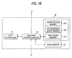
- FIG. 1B shows a block constitutional view of the apparatus operational condition controlling unit 18.
- the apparatus operational condition controlling unit 18 includes a grouping controlling unit 20, a step storing unit 21, a group memory 22, and an ordinary memory 23.
- the grouping controlling unit 20 controls the group selecting and registering processing of the operational conditions described later.
- the step storing unit 21 is a memory for storing the current processing state in the group selecting and registering processing of the operational conditions described later.
- the group memory 22 is a memory for storing various operational conditions classified into every group.
- the group memory 22 includes a group registration memory 22a, a recommended group memory 22b, and a past group memory 22c, in order to control the various operation conditions in every attribute.
- the group registration memory 22a is a memory for storing the newly registered group in the group selecting and registering processing described later. In reply to a predetermined operation such as end of application, the information within the group registration memory 22a is automatically transferred to the past group memory 22c.
- the recommended group memory 22b is a memory for storing various operational conditions previously registered (for example, in the manufacturing step before going on sale) as a recommended group.
- the past group memory 22c is a memory for storing various operational conditions having been registered as a group in the past.
- the ordinary memory 23 is a memory for storing the information about the conventional mode (hereinafter, referred to as "ordinary mode") of selecting some frequency from all the usable frequencies at a diagnostic time and using it.
- the group memory 22, or its components; the group registration memory 22a, the recommended group memory 22b, and the past group memory 22c, and the ordinary memory 23 may be formed in any shape such as a hard disk, FD, CD, and MD as long as it can store and provide electric data. From the viewpoint of preventing data deletion owing to malfunction, the recommended group memory 22b or the ordinary memory 23 may be formed in a read-only storing medium. When the respective memories are removable storing mediums, the information can be shared with the other ultrasonic diagnostic apparatus at ease. Further, it may be constituted in that the data within the respective memories is transferred to the external peripheral equipment, via a wired or a wireless network, not illustrated.
- the operational condition of the diagnostic apparatus means the set values of the parameters for executing the diagnostic operation including the transmitted pulse frequency, the depth of viewing field, the imaging mode, and the physical index (for example, the value of MI).
- the group selecting and registering processing of the transmitted pulse frequency will be described.
- This ultrasonic diagnostic apparatus 12 can group at least one desired parameter value and more and the types of modes in every predetermined operational condition of the diagnostic apparatus. For example, as illustrated on the left side of FIG. 2, assume that the ultrasonic diagnostic apparatus 12 can use five frequencies from the frequency A to the frequency E.
- the frequencies A, C, and E used by an operator who mainly examines the abdominal region are gathered together and at a diagnostic time, the operator can select one from the frequencies A, C, and E only.
- the groups 1 and 2 can be changed by a switch at any time. Needless to say, the number of the groups is not restricted to two.
- the group selecting and registering processing is the processing for this grouping (registration of the group) and selecting a group at a scanning time.
- the concrete contents will be described with reference to FIG. 3 to FIG. 12.
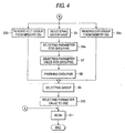
- FIG. 3 and FIG. 4 are flow charts showing the procedure of the group selecting and registering processing executed by this ultrasonic diagnostic apparatus 12.
- Step S1 the ultrasonic diagnostic apparatus 12 is turned on (Step S1), the ordinary mode or the grouped frequencies is selected, and one of the imaging modes to be used (hereinafter, referred to as "group mode") is selected (Step S2).
- group mode one of the imaging modes to be used
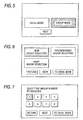
- FIG. 5 One example of the image display unit 13 or the display screen of TCS at this selecting time is shown in FIG. 5.
- Step S2 When selecting the ordinary mode in Step S2, information such as ID is entered (Step S12). Continuously, as it is the ordinary mode, a necessary operational condition is selected from the ordinary memory 23 (Steps S13 and S14), hence to execute the ultrasound diagnosis (Step S11).
- Step S3 While, when selecting the group mode in Step S2, information such as ID is entered (Step S3). Continuously, the grouping controlling unit 20 displays a screen, for example, shown in FIG. 6 and one of the new group registration mode, the recommended group selection mode, and the past group selection mode is selected (Step S4).
- the new group registration mode is a mode for making a new group of the operational conditions without using the operational conditions having been already grouped.
- the group registration memory 22a of FIG. 2 is mainly used.
- the recommended group selection mode is a mode for selecting a recommended group previously stored in the recommended group memory 22b.
- the past group selection mode is a mode for selecting a desired group from the groups, for example, having been already registered in this ultrasonic diagnostic apparatus 12 and stored in the past group memory 22c.
- Step S5 When selecting the new group registration mode in Step S4, the number or the group name for identifying a group to be newly registered is registered (Step S5).
- the group name may take an individual name of an operator or the scan region.
- the grouping controlling unit 20 controls the display screen of the image display unit 13 as shown in FIG. 7. In FIG. 7, an example of selecting one from the number 1 to the number 8 is shown, as the number for identifying a group.
- a parameter for grouping is selected (Step S6a).
- the other parameter for example, the imaging region may be used.
- FIG. 8 shows a screen example for selecting three parameters: the scan field, the frequency, and the depth of viewing field.
- the screen is shown on the image display unit 13 according to a control of the grouping controlling unit 20.
- the imaging mode means a mode for imaging and display, such as B mode, M mode, and C mode (color Doppler mode), and the depth of viewing field means the scannable depth within an object.
- a parameter value or contents to be registered as a group is selected (Step S7).
- the parameter value indicates the numeric value in each parameter.
- the parameter value means the respective B, M, and C modes.
- the frequency is used as the parameter, it means the respective frequency values.
- the depth of viewing field is used as the parameter, it means the respective values of the viewing field depth. All the selectable parameter values are stored previously in the ordinary memory 23.
- FIG. 9 shows an example of a display screen on the image display unit 13 for selecting the grouping frequency from 1 MHz to 12 MHz every 1 MHz.
- FIG. 9 when selecting three frequencies, 1, 3, and 5 MHz, from 1 to 12 MHz, and registering the above as the first group, it is one of the above three frequencies only that an operator can select if selecting the first group at a diagnostic time. Accordingly, a trouble of selecting a frequency to use from a lot of values can be saved, thereby speeding up the diagnostic work.
- Step S8 a message to the effect that the grouping will be finished, for example, as shown in FIG. 10, is displayed on the image display unit 13.
- a group to use is selected from the groups stored in the memory (Step S9).
- it is selected, based on the group number, or the other input item, if the other identifiable item is entered, set in Step S5.
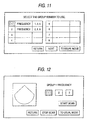
- FIG. 11 shows an example of a screen for selecting a group, displayed on the image display unit 13 in Step S9.
- Step S10 a parameter value used for a diagnosis is selected (Step S10), from the group selected in Step S9.
- FIG. 12 shows an example of a screen for selecting a parameter value, displayed on the image display unit 13 in Step S10.
- the first group consists of only the frequencies of 1, 3, and 5 MHz registered in Step 7.
- Step S10 After selecting a parameter value in Step S10, by pushing the button "SCAN START" shown in FIG. 12, the apparatus is set depending on the selected parameter value and a scan starts (Step S11). More specifically, the selected parameter value is sent to the transmission/reception controlling unit 15, or the image display controlling unit 16, or the other unit to be set if setting the other unit, through the signal processing unit 17 shown in FIG. 1, and the respective units are set hence to start a scan.
- the ultrasonic image displayed in the left central portion of FIG. 12 indicates the scanning result. It is preferable to display the operational condition at this scan, together with the ultrasonic image, on the image display unit 13.
- the finishing operation is performed in reply to a predetermined operation.
- the record in the group registration memory 22a is moved to the past group memory 22c.
- Step S4 As mentioned above, the case of selecting the new group registration mode in Step S4 has been described. The case of selecting the recommended group selection mode in Step S4 and the case of selecting the past group selecting mode will be described below.
- Step S4 When selecting the recommended group selection mode in Step S4, the group previously stored in the recommended group memory 22b is read out and displayed, for example, in the form shown in FIG. 11.
- An operator selects one proper group (Step S9), from the groups stored in the recommended group memory 22b according to the same operation, selects a parameter value of the above group (Step S10), and starts the scan (Step S11).
- Step S9 When selecting the past group selection mode in Step 42, only the registered group having been stored previously in the past group memory 22c is read out and displayed, for example, in the form shown in FIG. 11.
- An operator selects one proper group (Step S9), from the groups stored in the past group memory 22c according to the same operation, selects a parameter value of the above group (Step S10), and starts the scan (Step S11).
- a group especially used for an emergency may be stored in the past group memory 22c.
- the ultrasonic probe 11 and the input portion 14 are formed separately in this embodiment, the ultrasonic probe 11 may be provided with a function of the input portion 14.
- a function of selection like a trackball having a function belonging to the mouse, of the functions of the input portion 14, may be provided on the external lateral side of the ultrasonic probe 11. In this case, by rotating the trackball, the position of a pointer is moved on a screen, and by pushing the trackball, the corresponding item can be determined.
- the individual operators can use the different groups.
- the first modified example is not the form of selecting a specified one of the grouped parameter values and using it but the form of using all the grouped parameter values in a predetermined order.
- FIG. 13 is a flow chart showing the group selecting and registering processing in the modified example.
- the processing up to Step S9 is the same as the processing shown in FIG. 3 and FIG. 4.
- a selecting order of the parameter values within the group is determined (Step S10').
- the selecting order may be determined freely by an operator, or it may be automatically determined, like a decreasing order. For example, as illustrated in the group 1 shown in FIG. 2, when the frequencies A, C, and E are grouped together, the order may be determined as the order of the frequencies A, C, and E, or it may be determined as the order of the frequencies C, A, and E, as illustrated in FIG. 14.
- the selecting order can be determined concretely in a way of, with the frame of the frequency 1 MHz selected, dragging and dropping the above frame to the portion indicated by an arrow, and as a result, the selecting order becomes the frequencies 3 MHz, 1 MHz, and 5 MHz.
- Step S11 A scan is executed (Step S11) this time.
- the frequencies 1, 3, and 5 MHz are switched and used in the selecting order determined in Step 10', instead of selecting some frequency arbitrarily. Switching for use is performed by the input portion 14.
- the ultrasonic probe 11 may be provided with only a function of switching the parameter values, especially in the modified example.
- the probe 11 has to be provided with at least only one switch for switching the setting.
- it has to be provided with two switches; one for the regular order and the other for the inverse order to this. Therefore, the ultrasonic probe 11 can be downsized.
- the ultrasonic probe 11 is generally used, always gripped by hand, while an operator makes a diagnosis, when a switch for switching the parameter values is provided in the ultrasonic probe 11, operational ability is further improved and a quicker diagnosis can be achieved.
- the second modified example is to make a group under a plurality of operational conditions, not to do under a single operational condition like in the above-mentioned embodiment.
- the operational conditions mean three parameters; transmitted pulse frequency, depth of viewing field, and photoimaging mode, if the values or the contents of the three parameters are determined, the scanning condition is uniquely determined.
- the description will be made, by way of example, in the case of making a group under the operational conditions including three parameters of transmitted pulse frequency, depth of viewing field, and photoimaging mode.
- FIG. 16 is a flow chart showing the group selecting and registering processing in this modified example.
- the processing up to Step S5 and the processing of Step S8 and later is the same as the processing shown in FIG. 3 and FIG. 4.
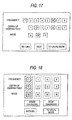
- FIG. 17 is an example of a screen displayed on the image display unit 13 in Step S6d of the flow chart shown in FIG. 16.
- Step S6d After registering the group name (Step S5) in FIG. 16, according to the contents of a screen displayed in FIG. 17, a plurality of parameter values are grouped (Step S6d). Namely, as illustrated in FIG. 17, the frequency includes 1 to 8 MHz in one MHz intervals, the depth of viewing field includes 1 to 8 cm in one cm intervals, and the mode includes B mode, M mode, and C mode (color mode). An operator selects a desired parameter value or desired contents while single-clicking only an item necessary for grouping with a mouse. In this modified example, as shown in the shaded portions, the operator selects the frequency of 1 and 6 MHz, the depth of viewing field of 2 and 5 cm, and the M mode.
- the operational condition to be registered as the same group can be selected and cancelled in every mode, frequency, and depth of viewing field, any number of times until an operator pushes the button "Next", for example, shown in the right bottom of FIG. 17.
- the object selected by the single click is again single-clicked, hence to be cancelled.
- Step S9 a desired group is selected (Step S9) in order to scan as shown in FIG. 4, and the parameter value to use is selected (Step S10).
- the selecting processing executed in this Step S10 is performed, for example, as follows, since this modified example is to make a group under a plurality operational conditions.
- FIG. 18 shows an example of a screen displayed on the image display unit 13 in Step S10 in this modified example.
- each combination (surrounded by a dotted line) is aligned in the order of the combination of the frequency 1 MHz, the depth of viewing field 2 cm, and the M mode, the combination of the frequency 1 MHz, the depth of viewing field 5 cm, and the M mode, and the like from the left side on the screen.
- An operator can select a desired combination, hence to do scanning according to the combination.
- the shaded portion in FIG. 18 shows the corresponding combination selected by an operator.
- Step S10 After the selection, the apparatus is set according to the combination, hence to start a diagnosis (Step S10).
- the several parameters and parameter values including the frequency, the depth of viewing field, and the photoimaging mode can be grouped on one screen. Accordingly, in addition to the effect of the embodiment, the grouping operation can be performed more efficiently and more suitable setting of an apparatus depending on an operator or the condition of a patient can be performed quickly.
- the above embodiments can be performed in a proper possible combination, and in this case, the combined effects can be obtained.
- the above embodiments include various steps of inventions and various inventions can be extracted by a proper combination of the disclosed elements. For example, even if some elements are deleted from the whole elements described in the embodiments, when it is possible to solve the problem as mentioned in the section of the problems to be solved by the invention and at least one of the effects as mentioned in the section of the effects of the invention can be obtained, the structure with the above elements deleted therefrom can be extracted as the invention.
- this invention can set a necessary apparatus quickly at a time of diagnosis. Accordingly, it is possible to improve the diagnostic efficiency of a patient and cope with an emergency diagnosis quickly.
Landscapes
- Life Sciences & Earth Sciences (AREA)
- Health & Medical Sciences (AREA)
- Biomedical Technology (AREA)
- Molecular Biology (AREA)
- Nuclear Medicine, Radiotherapy & Molecular Imaging (AREA)
- Pathology (AREA)
- Radiology & Medical Imaging (AREA)
- Engineering & Computer Science (AREA)
- Physics & Mathematics (AREA)
- Heart & Thoracic Surgery (AREA)
- Medical Informatics (AREA)
- Biophysics (AREA)
- Surgery (AREA)
- Animal Behavior & Ethology (AREA)
- General Health & Medical Sciences (AREA)
- Public Health (AREA)
- Veterinary Medicine (AREA)
- Ultra Sonic Daignosis Equipment (AREA)
- Measuring And Recording Apparatus For Diagnosis (AREA)
Abstract
Description
Claims (21)
- An ultrasonic diagnosis apparatus comprisingan input unit for selecting at least one frequency from a plurality of frequencies of ultrasonic pulse transmitted from an ultrasonic probe,a storing unit for storing at least the one frequency selected by the input unit as a frequency group, anda driving signal generator for generating a driving signal for driving the ultrasonic probe at the predetermined frequency specified when the input unit specifies a predetermined frequency from at least the one frequency forming the frequency group being stored.
- An ultrasonic diagnostic apparatus comprisinga storing unit for storing a plurality of frequency groups each consisting of at least one frequency of a plurality of frequencies of ultrasonic pulse transmitted from an ultrasonic probe,an input unit for specifying a predetermined frequency group from the frequency groups and specifying a predetermined frequency from at least the one frequency forming the predetermined frequency group, anda driving signal generator for generating a driving signal for driving the ultrasonic probe at the predetermined frequency specified by the input unit.
- An ultrasonic diagnosis apparatus comprisingan input unit for selecting two and more frequencies from a plurality of frequencies of ultrasonic pulse transmitted from an ultrasonic probe and specifying order of priority,a storing unit for storing the two and more frequencies selected by the input unit, together with the priority order, as a frequency group, anda driving signal generator for generating a driving signal for driving the ultrasonic probe at the two and more frequencies forming the frequency group, according to the priority order, when the input unit specifies the frequency group being stored.
- An ultrasonic diagnosis apparatus comprisingan input unit for selecting at least one parameter value as for a parameter as an operational condition of the apparatus,a storing unit for storing at least the one parameter value selected by the input unit as an operational condition group, anda controlling unit for generating a signal for controlling the apparatus at the predetermined parameter value specified when the input unit specifies a predetermined parameter value from at least the one parameter value forming the operational condition group being stored.
- The ultrasonic diagnosis apparatus, according to claim 4, whereinthe operational condition is one of transmitted pulse frequency, photoimaging mode, depth of viewing field, and physical index.
- An ultrasonic diagnostic apparatus comprisinga storing unit for storing a plurality of operational condition groups each consisting of at least one parameter value as for a predetermined parameter as an operational condition of the apparatus,an input unit for specifying a predetermined operational condition group from the operational condition groups and specifying a predetermined parameter value from at least the one parameter value forming the predetermined operational condition group, anda controlling unit for generating a signal for controlling the apparatus at the predetermined parameter value specified by the input unit.
- The ultrasonic diagnosis apparatus, according to claim 6, whereinthe operational condition is one of transmitted pulse frequency, photoimaging mode, depth of viewing field, and physical index.
- An ultrasonic diagnosis apparatus comprisingan input unit for specifying at least one combination set of parameter values as for an operation condition of the apparatus defined by a combination of at least two or more kinds of parameters,a storing unit for storing at least the one combination set of parameter values specified by the input unit as an operational condition group, anda controlling unit for generating a signal for controlling the apparatus according to the predetermined combination of parameter values specified when the input unit specifies a predetermined combination of parameter values from at least the one combination set of parameter values forming the operational condition group being stored.
- The ultrasonic diagnosis apparatus, according to claim 8, whereinat least one of at least two or more kinds of the parameters is one of transmitted pulse frequency, photoimaging mode, depth of viewing field, and physical index.
- An ultrasonic diagnostic apparatus comprisinga storing unit for storing a plurality of operational condition groups each consisting of at least one combination set of parameter values as for an operational condition of the apparatus defined by a combination of at least two or more kinds of parameters,an input unit for specifying a predetermined operational condition group from the operational condition groups and specifying a predetermined combination of parameter values from at least the one combination set of parameter values forming the predetermined operational condition group, anda controlling unit for generating a signal for controlling the apparatus in the predetermined combination of parameter values specified by the input unit.
- The ultrasonic diagnosis apparatus, according to claim 8, whereinat least one of at least two or more kinds of the parameters is one of transmitted pulse frequency, photoimaging mode, depth of viewing field, and physical index.
- A diagnosis apparatus comprisingan input unit for selecting at least one parameter value as for a parameter as an operational condition of the apparatus,a storing unit for storing at least the one parameter value selected by the input unit as an operational condition group, anda controlling unit for generating a signal for controlling the apparatus at the predetermined parameter value specified when the input unit specifies a predetermined parameter value from at least the one parameter value forming the stored operational condition group.
- The diagnosis apparatus, according to claim 12, which is one of an X-ray diagnosis apparatus, a computed tomography apparatus, a magnetic resonance imaging apparatus, and a nuclear medicine apparatus.
- A diagnostic apparatus comprisinga storing unit for storing a plurality of operational condition groups each consisting of at least one parameter value as for a parameter as an operational condition of the apparatus,an input unit for specifying a predetermined operational condition group from the operational condition groups and specifying a predetermined parameter value from at least the one parameter value forming the predetermined operational condition group, anda controlling unit for generating a signal for controlling the apparatus at the predetermined parameter value specified by the input unit.
- The diagnosis apparatus, according to claim 14, which is one of an X-ray diagnosis apparatus, a computed tomography apparatus, a magnetic resonance imaging apparatus, and a nuclear medicine apparatus.
- An operation controlling method of an ultrasonic diagnosis apparatus, comprisinga step of selecting at least one frequency from a plurality of frequencies of ultrasonic pulse transmitted from an ultrasonic probe,a step of registering at least one frequency selected by the input unit as a frequency group,a step of specifying a predetermined frequency from at least the one frequency forming the frequency group being registered, anda step of driving the ultrasonic probe at the specified predetermined frequency.
- An operation controlling method of an ultrasonic diagnostic apparatus, comprisinga step of specifying a predetermined frequency group from a plurality of frequency groups each consisting of at least one frequency of a plurality of frequencies of ultrasonic pulse transmitted from an ultrasonic probe,a step of specifying a predetermined frequency from at least the one frequency forming the predetermined frequency group, anda step of driving the ultrasonic probe at the specified predetermined frequency.
- An operation controlling method of a diagnosis apparatus, comprisinga step of selecting at least one parameter value as for a parameter as an operational condition of the apparatus,a step of storing at least the one parameter value selected above, as an operational condition group,a step of specifying a predetermined parameter value from at least the one parameter value forming the operational condition group being stored, by the input unit, anda step of controlling the apparatus at the specified predetermined parameter value.
- The operation controlling method of a diagnosis apparatus, according to claim 18, whereinthe diagnosis apparatus is one of an X-ray diagnosis apparatus, a computed tomography apparatus, a magnetic resonance imaging apparatus, and a nuclear medicine apparatus.
- An operation controlling method of a diagnosis apparatus, comprisinga step of specifying a predetermined operational condition group from a plurality of operational condition groups each consisting of at least one parameter value as for a parameter as an operational condition of the apparatus,a step of specifying a predetermined parameter value from at least the one parameter value forming the predetermined operational condition group, anda step of controlling the apparatus at the specified predetermined parameter value.
- The operation controlling method of a diagnosis apparatus, according to claim 20, whereinthe diagnosis apparatus is one of an X-ray diagnosis apparatus, a computed tomography apparatus, a magnetic resonance imaging apparatus, and a nuclear medicine apparatus.
Applications Claiming Priority (3)
| Application Number | Priority Date | Filing Date | Title |
|---|---|---|---|
| JP2000308964A JP2002113006A (en) | 2000-10-10 | 2000-10-10 | Diagnostic device setting method and diagnostic device |
| JP2000308964 | 2000-10-10 | ||
| PCT/JP2001/008891 WO2002030286A1 (en) | 2000-10-10 | 2001-10-10 | Diagnostic device, ultrasonic diagnostic device, and their operation control method |
Publications (3)
| Publication Number | Publication Date |
|---|---|
| EP1330984A1 true EP1330984A1 (en) | 2003-07-30 |
| EP1330984A4 EP1330984A4 (en) | 2005-02-09 |
| EP1330984B1 EP1330984B1 (en) | 2011-04-13 |
Family
ID=18789201
Family Applications (1)
| Application Number | Title | Priority Date | Filing Date |
|---|---|---|---|
| EP01974761A Expired - Lifetime EP1330984B1 (en) | 2000-10-10 | 2001-10-10 | Diagnostic device and its operation control method |
Country Status (7)
| Country | Link |
|---|---|
| US (1) | US7239907B2 (en) |
| EP (1) | EP1330984B1 (en) |
| JP (1) | JP2002113006A (en) |
| KR (1) | KR20030036902A (en) |
| CN (1) | CN1261079C (en) |
| DE (1) | DE60144433D1 (en) |
| WO (1) | WO2002030286A1 (en) |
Cited By (2)
| Publication number | Priority date | Publication date | Assignee | Title |
|---|---|---|---|---|
| EP1314394A3 (en) * | 2001-11-21 | 2004-01-14 | GE Medical Systems Global Technology Company LLC | Method and apparatus for prescribing an imaging scan and checking user input |
| EP2173252A4 (en) * | 2007-07-31 | 2010-12-15 | Unetixs Vascular Inc | Dual frequency doppler ultrasound probe |
Families Citing this family (17)
| Publication number | Priority date | Publication date | Assignee | Title |
|---|---|---|---|---|
| US6928316B2 (en) * | 2003-06-30 | 2005-08-09 | Siemens Medical Solutions Usa, Inc. | Method and system for handling complex inter-dependencies between imaging mode parameters in a medical imaging system |
| US20050131302A1 (en) * | 2003-12-16 | 2005-06-16 | Poland Mckee D. | Ultrasonic probe having a selector switch |
| JP2008206748A (en) * | 2007-02-27 | 2008-09-11 | Toshiba Corp | Ultrasonic diagnostic apparatus and ultrasonic diagnostic program |
| JP2009050372A (en) * | 2007-08-24 | 2009-03-12 | Ge Medical Systems Global Technology Co Llc | Ultrasonic diagnostic apparatus |
| US8150125B2 (en) * | 2007-10-29 | 2012-04-03 | Siemens Medical Solutions Usa, Inc. | System for visualizing regions of interest in medical images |
| JP5095380B2 (en) * | 2007-12-26 | 2012-12-12 | ジーイー・メディカル・システムズ・グローバル・テクノロジー・カンパニー・エルエルシー | Ultrasonic imaging device |
| CN101601593B (en) * | 2008-06-10 | 2013-01-16 | 株式会社东芝 | Ultrasonic diagnostic apparatus |
| KR20100011669A (en) * | 2008-07-25 | 2010-02-03 | (주)메디슨 | Method and device for providing customized interface in the ultrasound system |
| CN102793561A (en) * | 2011-05-24 | 2012-11-28 | 西门子公司 | Device and method for configuring ultrasonic scanning equipment |
| CN103096809B (en) | 2011-08-31 | 2015-11-25 | 株式会社东芝 | Diagnostic ultrasound equipment, ultrasonic diagnosis apparatus control method and medical diagnostic imaging apparatus |
| CN104011769A (en) | 2011-12-21 | 2014-08-27 | Sca卫生用品公司 | Method For Measuring The Absorption Of Fluid In An Absorbent Product |
| CN104434183A (en) * | 2013-09-16 | 2015-03-25 | 苏州边枫电子科技有限公司 | Integrated mechanical button wireless ultrasonic detection system |
| CN104887267B (en) * | 2015-06-03 | 2018-08-07 | 深圳开立生物医疗科技股份有限公司 | Optimize the method, apparatus and ultrasonic device of Ultrasonic Diagnosis operation according to patient information |
| CN109316201A (en) * | 2017-07-31 | 2019-02-12 | 柯尼卡美能达株式会社 | Diagnostic ultrasound equipment |
| CN107368697B (en) * | 2017-08-30 | 2020-09-22 | 上海联影医疗科技有限公司 | Virtual reality control system and method for medical equipment |
| CN110169788A (en) * | 2019-04-26 | 2019-08-27 | 青岛大学附属医院 | A kind of diasonograph preset mode selection method based on recognition of face |
| CN112220497A (en) * | 2020-11-11 | 2021-01-15 | 深圳开立生物医疗科技股份有限公司 | Ultrasonic imaging display method and related device |
Family Cites Families (41)
| Publication number | Priority date | Publication date | Assignee | Title |
|---|---|---|---|---|
| DE2311211C3 (en) * | 1973-03-07 | 1986-07-10 | Siemens AG, 1000 Berlin und 8000 München | X-ray diagnostic system with free and programmed setting of the exposure data |
| GB1448075A (en) * | 1974-05-23 | 1976-09-02 | Gec Medical Equipment Ltd | Radiographic apparatus |
| JPH02126226A (en) | 1988-11-07 | 1990-05-15 | Seiko Epson Corp | Liquid crystal electrooptic element |
| JPH03140146A (en) * | 1989-10-27 | 1991-06-14 | Toshiba Corp | Ultrasonic diagnostic device |
| JP2948282B2 (en) | 1990-08-03 | 1999-09-13 | 株式会社日立メディコ | Ultrasound diagnostic equipment |
| JP3059228B2 (en) * | 1991-02-28 | 2000-07-04 | 株式会社日立製作所 | Information processing device |
| JP3099901B2 (en) * | 1991-04-05 | 2000-10-16 | 株式会社東芝 | Ultrasound diagnostic equipment |
| US5325858A (en) * | 1992-01-10 | 1994-07-05 | Kabushiki Kaisha Toshiba | Ultrasonic imaging system capable of varying maximum pulse repetition frequency depending upon pulse transmission frequency |
| SG65570A1 (en) | 1992-02-25 | 1999-06-22 | Recordati Chem Pharm | Heterobicyclic compounds |
| JPH05253221A (en) * | 1992-03-13 | 1993-10-05 | Toshiba Corp | Ultrasonic diagnostic equipment |
| JPH05253220A (en) * | 1992-03-13 | 1993-10-05 | Toshiba Corp | Ultrasonic diagnostic equipment |
| JP3251696B2 (en) * | 1993-04-06 | 2002-01-28 | 株式会社東芝 | Ultrasound diagnostic equipment |
| US5315999A (en) * | 1993-04-21 | 1994-05-31 | Hewlett-Packard Company | Ultrasound imaging system having user preset modes |
| AU3361095A (en) * | 1994-08-05 | 1996-03-04 | Acuson Corporation | Method and apparatus for transmit beamformer system |
| US5553620A (en) * | 1995-05-02 | 1996-09-10 | Acuson Corporation | Interactive goal-directed ultrasound measurement system |
| US5544654A (en) * | 1995-06-06 | 1996-08-13 | Acuson Corporation | Voice control of a medical ultrasound scanning machine |
| JP3791849B2 (en) * | 1995-09-11 | 2006-06-28 | 株式会社東芝 | Medical image inspection device |
| US6430428B1 (en) * | 1995-10-25 | 2002-08-06 | Siemens Aktiengesellschaft | Imaging system for a medical diagnostic apparatus |
| US5805118A (en) * | 1995-12-22 | 1998-09-08 | Research Foundation Of The State Of New York | Display protocol specification with session configuration and multiple monitors |
| JP3685348B2 (en) * | 1996-01-23 | 2005-08-17 | 株式会社日立メディコ | Ultrasonic diagnostic equipment |
| JP3580627B2 (en) * | 1996-01-29 | 2004-10-27 | 株式会社東芝 | Ultrasound diagnostic equipment |
| US5603323A (en) * | 1996-02-27 | 1997-02-18 | Advanced Technology Laboratories, Inc. | Medical ultrasonic diagnostic system with upgradeable transducer probes and other features |
| US5868676A (en) * | 1996-10-25 | 1999-02-09 | Acuson Corporation | Interactive doppler processor and method |
| US5797846A (en) * | 1996-12-30 | 1998-08-25 | General Electric Company | Method to control frame rate in ultrasound imaging |
| JP3954154B2 (en) * | 1997-05-08 | 2007-08-08 | 株式会社東芝 | Ultrasonic diagnostic equipment |
| JPH10328179A (en) * | 1997-06-05 | 1998-12-15 | Toshiba Corp | Ultrasound diagnostic equipment |
| US5919138A (en) * | 1997-08-22 | 1999-07-06 | Acuson Corporation | Ultrasound imaging system user interface |
| JPH11206767A (en) | 1998-01-29 | 1999-08-03 | Toshiba Corp | Ultrasound diagnostic equipment |
| JP3586098B2 (en) * | 1998-05-21 | 2004-11-10 | オリンパス株式会社 | Ultrasound diagnostic imaging device |
| JP2000152928A (en) * | 1998-11-18 | 2000-06-06 | Toshiba Corp | Ultrasound diagnostic equipment |
| US6603494B1 (en) * | 1998-11-25 | 2003-08-05 | Ge Medical Systems Global Technology Company, Llc | Multiple modality interface for imaging systems including remote services over a network |
| GB2345543A (en) * | 1999-01-06 | 2000-07-12 | Intravascular Res Ltd | Ultrasonic visualisation system with remote components |
| JP2000254127A (en) * | 1999-03-12 | 2000-09-19 | Toshiba Iyo System Engineering Kk | Ultrasound diagnostic equipment |
| US6458081B1 (en) * | 1999-04-23 | 2002-10-01 | Kabushiki Kaisha Toshiba | Ultrasonic diagnostic apparatus |
| US6322505B1 (en) * | 1999-06-08 | 2001-11-27 | Acuson Corporation | Medical diagnostic ultrasound system and method for post processing |
| JP4702968B2 (en) * | 1999-08-25 | 2011-06-15 | 株式会社東芝 | Ultrasonic diagnostic equipment |
| US6306089B1 (en) * | 1999-09-24 | 2001-10-23 | Atl Ultrasound, Inc. | Ultrasonic diagnostic imaging system with customized measurements and calculations |
| US6411836B1 (en) * | 1999-12-30 | 2002-06-25 | General Electric Company | Method and apparatus for user preferences configuring in an image handling system |
| US6413218B1 (en) * | 2000-02-10 | 2002-07-02 | Acuson Corporation | Medical diagnostic ultrasound imaging system and method for determining an acoustic output parameter of a transmitted ultrasonic beam |
| JP2001299749A (en) * | 2000-04-27 | 2001-10-30 | Toshiba Medical System Co Ltd | Ultrasound image diagnostic equipment |
| US6527765B2 (en) * | 2000-10-06 | 2003-03-04 | Charles D. Kelman | Cryogenic surgical system and method of use in removal of tissue |
-
2000
- 2000-10-10 JP JP2000308964A patent/JP2002113006A/en active Pending
-
2001
- 2001-10-10 EP EP01974761A patent/EP1330984B1/en not_active Expired - Lifetime
- 2001-10-10 KR KR10-2003-7004995A patent/KR20030036902A/en not_active Ceased
- 2001-10-10 WO PCT/JP2001/008891 patent/WO2002030286A1/en not_active Ceased
- 2001-10-10 CN CNB018171826A patent/CN1261079C/en not_active Expired - Fee Related
- 2001-10-10 DE DE60144433T patent/DE60144433D1/en not_active Expired - Lifetime
-
2003
- 2003-04-10 US US10/410,264 patent/US7239907B2/en not_active Expired - Fee Related
Cited By (2)
| Publication number | Priority date | Publication date | Assignee | Title |
|---|---|---|---|---|
| EP1314394A3 (en) * | 2001-11-21 | 2004-01-14 | GE Medical Systems Global Technology Company LLC | Method and apparatus for prescribing an imaging scan and checking user input |
| EP2173252A4 (en) * | 2007-07-31 | 2010-12-15 | Unetixs Vascular Inc | Dual frequency doppler ultrasound probe |
Also Published As
| Publication number | Publication date |
|---|---|
| US20030208118A1 (en) | 2003-11-06 |
| EP1330984A4 (en) | 2005-02-09 |
| WO2002030286A1 (en) | 2002-04-18 |
| DE60144433D1 (en) | 2011-05-26 |
| EP1330984B1 (en) | 2011-04-13 |
| CN1261079C (en) | 2006-06-28 |
| US7239907B2 (en) | 2007-07-03 |
| CN1469722A (en) | 2004-01-21 |
| KR20030036902A (en) | 2003-05-09 |
| JP2002113006A (en) | 2002-04-16 |
Similar Documents
| Publication | Publication Date | Title |
|---|---|---|
| EP1330984B1 (en) | Diagnostic device and its operation control method | |
| JP5846755B2 (en) | Image diagnostic apparatus and medical image display apparatus | |
| US6540676B2 (en) | Ultrasonic diagnostic apparatus and operating sequence determining method of the ultrasonic diagnostic apparatus | |
| US6827684B2 (en) | Medical diagnostic apparatus with a function for preventing oversight omissions of data collection items | |
| US12390195B2 (en) | Ultrasound diagnosis apparatus and image processing apparatus | |
| JP2006503620A (en) | System and method for improving the display of diagnostic images | |
| JP5417048B2 (en) | Ultrasonic diagnostic apparatus and ultrasonic diagnostic program | |
| JP2003290224A (en) | Medical image diagnostic apparatus, its maintenance management method, and its maintenance management system | |
| CN112704515A (en) | Doppler parameter adjusting method and related equipment | |
| EP1934864B1 (en) | Method for creating and managing ultrasound measurment-based calculations in ultrasound imaging systems | |
| CN103140174B (en) | Ultrasonic diagnostic equipment, image processing equipment | |
| JPH0838433A (en) | Medical image diagnostic equipment | |
| JPS6244495B2 (en) | ||
| JP6744443B2 (en) | Ultrasound image diagnostic apparatus and program | |
| JP6744073B2 (en) | Ultrasonic diagnostic device and ultrasonic image diagnostic display system | |
| US20050114175A1 (en) | Method and apparatus for managing ultrasound examination information | |
| JP2021186257A (en) | Medical image diagnostic apparatus and medical image processing apparatus | |
| JP3067104B2 (en) | Image processing method and apparatus, and medical image apparatus | |
| JP2002282250A (en) | Ultrasound imaging diagnostic equipment | |
| JP5053548B2 (en) | Ultrasonic diagnostic apparatus and control program for ultrasonic diagnostic apparatus | |
| JP5443781B2 (en) | Ultrasonic diagnostic equipment | |
| JP2001314399A (en) | Ultrasound image diagnostic equipment | |
| JP2014239841A (en) | Ultrasonic diagnostic equipment, medical image processor, and control program | |
| JP2012254145A (en) | Medical image diagnostic apparatus and image processing apparatus | |
| JPH10314169A (en) | Ultrasound diagnostic equipment |
Legal Events
| Date | Code | Title | Description |
|---|---|---|---|
| PUAI | Public reference made under article 153(3) epc to a published international application that has entered the european phase |
Free format text: ORIGINAL CODE: 0009012 |
|
| 17P | Request for examination filed |
Effective date: 20030502 |
|
| AK | Designated contracting states |
Designated state(s): DE NL |
|
| A4 | Supplementary search report drawn up and despatched |
Effective date: 20041223 |
|
| RIC1 | Information provided on ipc code assigned before grant |
Ipc: 7A 61B 8/00 A Ipc: 7G 01S 7/52 B |
|
| 17Q | First examination report despatched |
Effective date: 20081113 |
|
| GRAP | Despatch of communication of intention to grant a patent |
Free format text: ORIGINAL CODE: EPIDOSNIGR1 |
|
| RTI1 | Title (correction) |
Free format text: DIAGNOSTIC DEVICE AND ITS OPERATION CONTROL METHOD |
|
| GRAS | Grant fee paid |
Free format text: ORIGINAL CODE: EPIDOSNIGR3 |
|
| GRAA | (expected) grant |
Free format text: ORIGINAL CODE: 0009210 |
|
| REG | Reference to a national code |
Ref country code: DE Ref legal event code: R081 Ref document number: 60144433 Country of ref document: DE Owner name: TOSHIBA MEDICAL SYSTEMS CORPORATION, OTAWARA-S, JP Free format text: FORMER OWNER: KABUSHIKI KAISHA TOSHIBA, TOKYO, JP |
|
| AK | Designated contracting states |
Kind code of ref document: B1 Designated state(s): DE NL |
|
| REF | Corresponds to: |
Ref document number: 60144433 Country of ref document: DE Date of ref document: 20110526 Kind code of ref document: P |
|
| REG | Reference to a national code |
Ref country code: DE Ref legal event code: R096 Ref document number: 60144433 Country of ref document: DE Effective date: 20110526 |
|
| REG | Reference to a national code |
Ref country code: NL Ref legal event code: T3 |
|
| PLBE | No opposition filed within time limit |
Free format text: ORIGINAL CODE: 0009261 |
|
| STAA | Information on the status of an ep patent application or granted ep patent |
Free format text: STATUS: NO OPPOSITION FILED WITHIN TIME LIMIT |
|
| 26N | No opposition filed |
Effective date: 20120116 |
|
| REG | Reference to a national code |
Ref country code: DE Ref legal event code: R097 Ref document number: 60144433 Country of ref document: DE Effective date: 20120116 |
|
| REG | Reference to a national code |
Ref country code: NL Ref legal event code: PD Owner name: TOSHIBA MEDICAL SYSTEMS CORPORATION; JP Free format text: DETAILS ASSIGNMENT: VERANDERING VAN EIGENAAR(S), OVERDRACHT; FORMER OWNER NAME: KABUSHIKI KAISHA TOSHIBA Effective date: 20160627 |
|
| REG | Reference to a national code |
Ref country code: DE Ref legal event code: R081 Ref document number: 60144433 Country of ref document: DE Owner name: TOSHIBA MEDICAL SYSTEMS CORPORATION, OTAWARA-S, JP Free format text: FORMER OWNER: KABUSHIKI KAISHA TOSHIBA, TOKIO/TOKYO, JP Ref country code: DE Ref legal event code: R082 Ref document number: 60144433 Country of ref document: DE Representative=s name: KRAMER BARSKE SCHMIDTCHEN PATENTANWAELTE PARTG, DE |
|
| PGFP | Annual fee paid to national office [announced via postgrant information from national office to epo] |
Ref country code: DE Payment date: 20171004 Year of fee payment: 17 |
|
| PGFP | Annual fee paid to national office [announced via postgrant information from national office to epo] |
Ref country code: NL Payment date: 20171016 Year of fee payment: 17 |
|
| REG | Reference to a national code |
Ref country code: DE Ref legal event code: R119 Ref document number: 60144433 Country of ref document: DE |
|
| REG | Reference to a national code |
Ref country code: NL Ref legal event code: MM Effective date: 20181101 |
|
| PG25 | Lapsed in a contracting state [announced via postgrant information from national office to epo] |
Ref country code: DE Free format text: LAPSE BECAUSE OF NON-PAYMENT OF DUE FEES Effective date: 20190501 Ref country code: NL Free format text: LAPSE BECAUSE OF NON-PAYMENT OF DUE FEES Effective date: 20181101 |