EP1330910B1 - Procede et systeme de reduction des effets d'interference entre-symboles dans la transmission par une liaison serie avec un mappage de chaque mot d'une grappe de mots re us vers un seul mot transmis - Google Patents
Procede et systeme de reduction des effets d'interference entre-symboles dans la transmission par une liaison serie avec un mappage de chaque mot d'une grappe de mots re us vers un seul mot transmis Download PDFInfo
- Publication number
- EP1330910B1 EP1330910B1 EP02759623A EP02759623A EP1330910B1 EP 1330910 B1 EP1330910 B1 EP 1330910B1 EP 02759623 A EP02759623 A EP 02759623A EP 02759623 A EP02759623 A EP 02759623A EP 1330910 B1 EP1330910 B1 EP 1330910B1
- Authority
- EP
- European Patent Office
- Prior art keywords
- words
- word
- code words
- preferred
- bit
- Prior art date
- Legal status (The legal status is an assumption and is not a legal conclusion. Google has not performed a legal analysis and makes no representation as to the accuracy of the status listed.)
- Expired - Lifetime
Links
Images


Classifications
-
- H—ELECTRICITY
- H04—ELECTRIC COMMUNICATION TECHNIQUE
- H04L—TRANSMISSION OF DIGITAL INFORMATION, e.g. TELEGRAPHIC COMMUNICATION
- H04L1/00—Arrangements for detecting or preventing errors in the information received
- H04L1/004—Arrangements for detecting or preventing errors in the information received by using forward error control
- H04L1/0056—Systems characterized by the type of code used
- H04L1/0057—Block codes
-
- H—ELECTRICITY
- H04—ELECTRIC COMMUNICATION TECHNIQUE
- H04L—TRANSMISSION OF DIGITAL INFORMATION, e.g. TELEGRAPHIC COMMUNICATION
- H04L1/00—Arrangements for detecting or preventing errors in the information received
- H04L1/20—Arrangements for detecting or preventing errors in the information received using signal quality detector
- H04L1/203—Details of error rate determination, e.g. BER, FER or WER
-
- H—ELECTRICITY
- H04—ELECTRIC COMMUNICATION TECHNIQUE
- H04L—TRANSMISSION OF DIGITAL INFORMATION, e.g. TELEGRAPHIC COMMUNICATION
- H04L1/00—Arrangements for detecting or preventing errors in the information received
- H04L1/20—Arrangements for detecting or preventing errors in the information received using signal quality detector
- H04L1/206—Arrangements for detecting or preventing errors in the information received using signal quality detector for modulated signals
-
- H—ELECTRICITY
- H04—ELECTRIC COMMUNICATION TECHNIQUE
- H04L—TRANSMISSION OF DIGITAL INFORMATION, e.g. TELEGRAPHIC COMMUNICATION
- H04L25/00—Baseband systems
- H04L25/38—Synchronous or start-stop systems, e.g. for Baudot code
- H04L25/40—Transmitting circuits; Receiving circuits
- H04L25/49—Transmitting circuits; Receiving circuits using code conversion at the transmitter; using predistortion; using insertion of idle bits for obtaining a desired frequency spectrum; using three or more amplitude levels ; Baseband coding techniques specific to data transmission systems
-
- H—ELECTRICITY
- H04—ELECTRIC COMMUNICATION TECHNIQUE
- H04N—PICTORIAL COMMUNICATION, e.g. TELEVISION
- H04N19/00—Methods or arrangements for coding, decoding, compressing or decompressing digital video signals
- H04N19/85—Methods or arrangements for coding, decoding, compressing or decompressing digital video signals using pre-processing or post-processing specially adapted for video compression
- H04N19/89—Methods or arrangements for coding, decoding, compressing or decompressing digital video signals using pre-processing or post-processing specially adapted for video compression involving methods or arrangements for detection of transmission errors at the decoder
-
- G—PHYSICS
- G09—EDUCATION; CRYPTOGRAPHY; DISPLAY; ADVERTISING; SEALS
- G09G—ARRANGEMENTS OR CIRCUITS FOR CONTROL OF INDICATING DEVICES USING STATIC MEANS TO PRESENT VARIABLE INFORMATION
- G09G5/00—Control arrangements or circuits for visual indicators common to cathode-ray tube indicators and other visual indicators
- G09G5/003—Details of a display terminal, the details relating to the control arrangement of the display terminal and to the interfaces thereto
- G09G5/006—Details of the interface to the display terminal
Definitions
- the invention relates to a communication system, a receiver and a method for transmitting encoded data over a serial link.
- the invention pertains to transmission of encoded data (e.g., one or both of video data and auxiliary data such as audio data) over a serial link, in such a manner as to reduce the bit error rate resulting from inter-symbol interference or other error-causing effects during transmission.
- the serial link is a transition minimized differential signaling ("TMDS") link, or a link having some but not all of the characteristics of a TMDS link.
- TMDS transition minimized differential signaling
- Elements of this invention are based upon properties of a serial link.
- Various serial links for transmitting data and clock signals are well known.
- TMDS transition minimized differential signaling interface
- a use of the TMDS serial link is the "Digital Visual Interface” interface ("DVI" link) adopted by the Digital Display Working Group. It will be described with reference to Fig. 1 .
- DVI link can be implemented to include two TMDS links (which share a common conductor pair for transmitting a video clock signal) or one TMDS link, as well as additional control lines between the transmitter and receiver.
- DDC Display Data Channel
- HPD Hot Plug Detect
- the Display Data Channel standard specifies a protocol for bidirectional communication between a transmitter and a monitor associated with a receiver, including transmission by the monitor of an Extended Display Identification (“EDID") message that specifies various characteristics of the monitor, and transmission by the transmitter of control signals for the monitor.
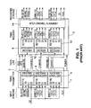
- Transmitter 1 includes three identical encoder/serializer units (units 2, 4, and 6) and additional circuitry (not shown).
- Receiver 3 includes three identical recovery/decoder units (units 8, 10, and 12) and inter-channel alignment circuitry 14 connected as shown, and additional circuitry (not shown).
- circuit 2 encodes the data to be transmitted over Channel 0, and serializes the encoded bits.
- circuit 4 encodes the data to be transmitted over Channel 1 (and serializes the encoded bits), and circuit 6 encodes the data to be transmitted over Channel 2 (and serializes the encoded bits).
- Each of circuits 2, 4, and 6 responds to a control signal (an active high binary control signal referred to as a "data enable" or "DE" signal) by selectively encoding either digital video words (in response to DE having a high value) or a control or synchronization signal pair (in response to DE having a low value).
- DE data enable
- encoder 2 receives horizontal and vertical synchronization signals (HSYNC and VSYNC); encoder 4 receives control bits CTL0 and CTL1; and encoder 6 receives control bits CTL2 and CTL3.
- each of encoders 2, 4, and 6 generates in-band words indicative of video data (in response to DE having a high value), encoder 2 generates out-of-band words indicative of the values of HSYNC and VSYNC (in response to DE having a low value), encoder 4 generates out-of-band words indicative of the values of CTL0 and CTL1 (in response to DE having a low value), and encoder 6 generates out-of-band words indicative of the values of CTL2 and CTL3 (in response to DE having a low value).
- each of encoders 4 and 6 In response to DE having a low value, each of encoders 4 and 6 generates one of four specific out-of-band words indicative of the values 00, 01, 10, or 11, respectively, of control bits CTL0 and CTL1 (or CTL2 and CTL3).
- HDCP High-bandwidth Digital Content Protection
- a DVI transmitter implementing HDCP outputs a 24-bit bus, known as cout [23:0], during the video active period (i.e. when DE is high).
- This 24-bit cout data is "Exclusive Ored” (in logic circuitry in the transmitter) with the 24-bit RGB video data input to the transmitter in order to encrypt the video data.
- the encrypted data is then encoded (according to the TMDS standard) for transmission.
- the same cout data is also generated in the receiver. After the encoded and encrypted data received at the receiver undergoes TMDS decoding, the cout data is processed together with the decoded video in logic circuitry in order to decrypt the decoded data and recover the original input video data.
- the transmitter and receiver communicate bidirectionally with each other to execute an authentication protocol (to verify that the receiver is authorized to receive protected content, and to establish shared secret values for use in encryption of input data and decryption of transmitted encrypted data).
- the transmitter calculates the initial set of encryption keys (for encrypting the first line of input video data) in response to a control signal and sends the control signal to the receiver (during each vertical blanking period, when DE is low) to cause the receiver to calculate an initial set of decryption keys (for decrypting the first received and decoded line of transmitted video data).
- each of the transmitter and receiver performs a re-keying operation during each blanking (vertical or horizontal) interval to generate a new set of keys for encrypting (or decrypting) the next line of video data, and actual encryption of input video data (or decryption of received, decoded video data) is performed using the latest set of keys only when DE is high (not during the blanking intervals).
- Each of the transmitter and receiver includes an HDCP cipher circuit (sometimes referred to herein as an "HDCP cipher") including a linear feedback shift register (LFSR) module, a block module coupled to the output of the LFSR module, and an output module coupled to an output of the block module.
- the LFSR module is employed to re-key the block module in response to each assertion of an enable signal, using a session key (Ks) and frame key (Ki).
- the block module generates (and provides to the LFSR module) the key Ks at the start of a session and generates (and applies to the LFMS module) a new value of key Ki at the start of each frame of video data (in response to a rising edge of a control signal which occurs in the first vertical blanking interval of a frame).
- the block module comprises two halves, known as "Round Function K” and "Round Function B.”
- Round Function K includes 28-bit registers Kx, Ky, and Kz, seven S-Boxes (each a 4 input bit by 4 output bit S-Box including a look-up table), and a linear transformation unit K.
- Round Function B includes 28-bit registers Bx, By, and Bz, seven S-Boxes (each a 4 input bit by 4 output bit S-Box including a look-up table), and a linear transformation unit B.
- Round Function K and Round Function B are similar in design, but Round Function K performs one round of a block cipher per clock cycle to assert (to the output module) a different pair of 28-bit round keys (Ky and Kz) each clock cycle in response to the output of the LFSR module, and Round Function B performs one round of a block cipher per clock cycle, in response to each 28-bit round key Ky from Round Function K and the output of the LFSR module, to assert (to the output module) a different pair of 28-bit round keys (By and Bz ) each clock cycle.
- the transmitter generates value An at the start of the authentication protocol and the receiver responds to it during the authentication procedure.
- the value An is used to randomize the session key.
- the block module operates in response to the authentication value (An) and an initialization value (Mi, also referred to as an integrity verification key) which is updated by the output module at the start of each frame.
- Each of linear transformation units K and B outputs 56 bits per clock cycle. These output bits are the combined outputs of eight diffusion networks in each transformation unit.
- Each diffusion network of linear transformation unit K produces seven output bits in response to seven of the current output bits of registers Ky and Kz.
- Each of four of the diffusion networks of linear transformation unit B produces seven output bits in response to seven of the current output bits of registers By, Bz, and Ky, and each of the four other diffusion networks of linear transformation unit B produces seven output bits in response to seven of the current output bits of registers By and Bz.
- the output module performs a compression operation on the 28-bit keys (By, Bz, Ky and Kz ) asserted to it (a total of 112 bits) by the block module during each clock cycle, to generate one 24-bit block of pseudo-random bits cout[23:0] per clock cycle.
- Each of the 24 output bits of the output module consists of the exclusive OR ("XOR") of nine terms.
- logic circuitry receives each 24-bit block of cout data and each input 24-bit RGB video data word, and performs a bitwise XOR operation thereon in order to encrypt the video data, thereby generating a word of encrypted RGB video data.
- the encrypted data subsequently undergoes TMDS encoding before it is transmitted to a receiver.
- logic circuitry receives each 24-bit block of cout data and each recovered 24-bit RGB video data word (after the recovered data has undergone TMDS decoding), and performs a bitwise XOR operation thereon in order to decrypt the recovered video data.
- TMDS-like link will sometimes be used to denote a serial link capable of transmitting encoded data (e.g., encoded digital video data) and a clock for the encoded data, from a transmitter to a receiver, and optionally also capable of transmitting (bidirectionally or unidirectionally) one or more additional signals (e.g., encoded digital audio data or other encoded data) between the transmitter and receiver, that is or includes either a TMDS link or a link having some but not all of the characteristics of a TMDS link.
- encoded data e.g., encoded digital video data
- additional signals e.g., encoded digital audio data or other encoded data
- Some TMDS-like links encode input video data (and other data) to be transmitted into encoded words comprising more bits than the incoming data using a coding algorithm other than the specific algorithm used in a TMDS link, and transmit the encoded video data as in-band characters and the other encoded data as out-of-band characters.
- the characters need not be classified as in-band or out-of-band characters based according to whether they satisfy transition minimization and DC balance criteria. Rather, other classification criteria could be used.
- An example of an encoding algorithm, other than that used in a TMDS link but which could be used in a TMDS-like link, is IBM 8b10b coding.
- the classification (between in-band and out-of-band characters) need not be based on just a high or low number of transitions.
- the number of transitions of each of the in-band and out-of-band characters could (in some embodiments) be in a single range (e.g., a middle range defined by a minimum and a maximum number of transitions).
- the data transmitted between the transmitter and receiver of a TMDS-like link can, but need not, be transmitted differentially (over a pair of conductors). Also, although a TMDS link has four differential pairs (in the single pixel version), three for video data and the other for a video clock, a TMDS-like link could have a different number of conductors or conductor pairs.
- the primary data transmitted by a TMDS link are video data. What is often significant about this is that the video data are not continuous, and instead have blanking intervals. These blanking intervals provide an opportunity (exploited in some embodiments of the present invention) for auxiliary data to be transported, and they represent unused bandwidth.
- many serial links do not transmit data having blanking intervals, and thus do not encode input data (for transmission) in response to a data enable signal. For example, audio serial links would typically transmit continuous data.
- auxiliary data is used in a broad sense herein to denote digital audio data or any other type of data other than video data and timing information for video data (e.g., a video clock).
- timing information for audio data e.g., a clock for recovering transmitted audio data
- auxiliary data transmitted in accordance with the invention include computer keyboard signals, still image data (generated by a camera, for example), text data, control signals for a power supply, picture in picture data, monitor control information (audio volume, brightness, power state), control signals for indicator lights on a monitor or keyboard, non-audio or video control information, etc.
- the term "stream” of data denotes that all the data are of the same type and is transmitted with the same clock frequency.
- channel refers to that portion of a serial link that is employed to transmit data (e.g., a particular conductor or conductor pair between the transmitter and receiver over which the data are transmitted, and specific circuitry within the transmitter and/or receiver used for transmitting and/or recovery of the data) and to the technique employed to transmit the data over the link. Because it is desirable to transmit many different streams of auxiliary data in important applications of the invention, preferred embodiments of the invention provide multiple channels for transmission of auxiliary data, including channels for transmission of auxiliary data in both directions over the link (that is, with and against the direction of the video data).
- a channel is employed to transmit one stream of auxiliary data. In other implementations, a channel is employed to transmit more than one stream of auxiliary data. In some embodiments of the invention, two (or more than two) streams of serial video data are transmitted (over one, two, or more than two channels), and either one, two, or more than two streams of serial auxiliary data are also transmitted.
- U.S. Patent 5,999,571, issued December 7, 1999 teaches (e.g., at col. 5) that, when the code words (indicative of video data) transmitted over a TMDS link are transition minimized words (a first subset of a set of code words), synchronization words (distinguishable from the transition minimized code words) can be transmitted over the link during "preamble" periods in which encoded video data are not transmitted.
- the synchronization words can be transition maximized words that are members of a second subset (disjoint from the first subset) of the set of code words.
- 5,999,571 teaches that several (e.g., three) repetitions of a synchronization word should be transmitted consecutively, to allow the decoder (in the receiver) rapidly and accurately to identify a specific transition (e.g., the leading edge) of one of the synchronization words and thus to accomplish synchronization with the encoder (in the transmitter.
- U.S. Patent 6,151,334, issued November 21, 2000 teaches transmission (over a TMDS link) of several different types of encoded control words, each distinguishable from transition minimized code words indicative of data. At least some of the control words can be transition maximized words.
- One of the control words is a "data stream separation" word that is transmitted before or after a burst of data and is indicative of the start or end of a burst and the type of data transmitted during the burst.
- Another one of the control words is an "isochronous data transfer" word that is a synchronization character typically transmitted at the beginning or end of a blanking interval and indicates the type of the blanking interval (e.g., horizontal or vertical) and distinguishes between the beginning and the end of the blanking interval.
- a first isochronous data transfer word indicates the start of a vertical blanking interval
- a first data stream separation word indicates the start of a burst of data in the vertical blanking interval
- a second data stream separation word indicates the end of such data burst
- a second isochronous data transfer word indicates the end of the vertical blanking interval
- Each of the first isochronous data transfer word, the first data stream separation word, the second data stream separation word, and the second isochronous data transfer word is a transition maximized code word
- a transition minimized code word can indicate each word of data of the data burst (transmitted in the vertical blanking interval)
- the vertical blanking interval can be followed by an active video period comprising a third data stream separation word (indicative of the start of a stream of video data) followed by a stream of transition minimized code words indicative of the video data itself.
- US-B-6 208 715 there is described a communication system and a receiver according to the preamble of claims 1 and 33.
- a method for transmitting encoded data over a serial link according to the preamble of claim 46 is also known from US-B-6 208 715 .
- US-B-6 208 715 discloses digital telecommunication systems and methods that employ selected code words to encode messages to be transmitted with encoded speech data and perform error correction on the received message words to correct transmission errors.
- the object of the present invention is to provide transmission of encoded video data and auxiliary data over a serial link, in such a manner as to reduce the bit error rate during transmission.
- the communication system and the receiver of the invention are characterized by the features claimed in the characterizing part of claim 1 and 33 and the invention provides a method according to the characterizing part of claim 46.
- the invention is a communication system including a transmitter, a receiver, and a serial link (which can but need not be a TMDS or TMDS-like link), in which encoded data (e.g., encoded video data and optionally also encoded auxiliary data) are transmitted from the transmitter to the receiver.
- the serial link can but need not be a TMDS or TMDS-like link.
- alternating bursts of encoded video data and encoded auxiliary data are transmitted over each of one or more channels of a serial link.
- bursts of encoded video data are transmitted over a serial link
- one or more bursts of encoded auxiliary data are, or no burst of encoded auxiliary data is, transmitted in each blanking interval between bursts of the encoded video data.
- Other aspects of the invention are transmitters for use in encoding data for transmission over a serial link, receivers for receiving and decoding encoded data transmitted over a serial link, and methods for sending encoded data over a serial link.
- the source data to be transmitted are encoded using a "robust" subset of a full set of code words.
- Each "robust" subset consists of code word sets (sometimes referred to herein as “golden sets”), with each golden set consisting of one or more code words (sometimes referred to herein as “golden words” or “preferred words”).
- Each golden word of a golden set is indicative of a single source data value (e.g., a source data word).
- a golden set consists of two or more golden words
- each of these golden words is indicative of the same source data value. Disjoint clusters of code words in the full set are determined.
- Each cluster includes a "golden set” and optionally also one or more additional code words of the full set, where each of the additional code words is "similar" to a golden word of the cluster's golden set in the sense that each additional code word is likely to be generated as a result of probable bit errors in transmission, or transmission and decoding, of such golden word.
- Each received code word in one of the clusters is mapped to the source data value determined by the cluster's golden set.
- Each mapping of a cluster of received code words to a single source data value can provide error correction by mapping an error-containing word in the cluster back to the source data value most likely to correspond to the error-containing word.
- the full set of code words can be used to encode one type of data (e.g., video data) for transmission over a channel of a serial link, and the robust subset can be used to encode another type of data (e.g., audio data or other "auxiliary" data related to or useful with video data) for transmission over the same channel.
- one type of data e.g., video data
- the robust subset can be used to encode another type of data (e.g., audio data or other "auxiliary" data related to or useful with video data) for transmission over the same channel.
- each code word in each golden set (and each code word in the full set) is an N-bit word that is an encoded version of an M-bit word, where M is an integer less than N.
- each received N-bit code word can differ from one of the golden words (if a transmission error has occurred) or it can be identical to one of the transmitted golden words.
- Each received N-bit code word in one of the clusters is decoded to generate a decoded M-bit word, and each such decoded M-bit word is mapped to the source data value determined by the cluster's golden set.
- the full set of code words is the set of 10-bit TMDS-encoded words that are indicative of 256 eight-bit source words.
- the robust subset of the full set consists of eight-bit "golden words" indicative of a subset of the full set of 256 eight-bit source words.
- the robust subset consists of sixteen golden sets, each golden set consists of the 10-bit TMDS code words indicative of one eight-bit source word, and each cluster of the 10-bit TMDS code words includes one of the golden sets and at least one 10-bit TMDS code words similar to the code words in such golden set.
- each received 10-bit code word in one of the clusters is decoded in accordance with the TMDS decoding algorithm (or a modified version of such algorithm) to recover an eight-bit word, and each recovered eight-bit word is mapped to the eight-bit source word determined by the cluster.
- TMDS decoding algorithm or a modified version of such algorithm
- each cluster is a set of 10-bit TMDS code words that can be decoded (in accordance with the TMDS decoding algorithm or modified version thereof) to a set of N i eight-bit words, S ij (including the eight-bit source word determined by the cluster), where the index "i" denotes one of the sixteen clusters, the index "j” is an integer in the range 1 ⁇ j ⁇ N i , and the integer N i need not be the same for all different values of the index "i.”
- the words S 2j consist of the source word identified by the second cluster and N 2 -1 other eight-bit words "similar” to this source word, and so on.
- the code words in the full set have equal length (e.g., each consists of N bits).
- the robust subset will sometimes be referred to herein as a "selected” (or “inventive") set of code words, and the code words in the robust subset will sometimes referred to as the “inventive” code words (or as “golden words”).
- the robust subset is selected such that each stream of encoded data (comprising only inventive code words) transmitted over a serial link has a bit pattern that is less susceptible to inter-symbol interference ("ISI") during transmission than is the bit pattern determined by a transmitted, conventionally encoded version of the same data (comprising not only inventive code words but also members of the full set that are not inventive code words).
- ISI inter-symbol interference
- the bit rate at which source data can be transmitted over the link is lower if the transmitted data are encoded using only the inventive code words than if the transmitted data are encoded conventionally using the full code word set. This is because, in general, a set of source data bits can be grouped into a fewer number of longer source data words (each different source data word to be encoded as a different L-bit code word) when more different L-bit code words are available for encoding the source data.
- the best choice for the particular inventive code word set selected from a full set of binary code words depends on the particular coding implemented by the full set (i.e., the details of which bits of each code word in the full set are zeroes and which are ones).
- the inventive code words are predetermined to be those whose serial patterns (during transmission) have fewer contiguous zeros and ones (e.g., on the average), and thus are less susceptible to ISI during transmission, than do those code words in the full set that are not selected (e.g., the average number of contiguous zeros and ones, per code word, of the inventive code words is less than the average number of contiguous zeros and ones, per code word, of the code words in the full set that are not selected as the inventive code words).
- the bit pattern of each transmitted stream of the inventive code words preferably implements DC balancing (the voltage drift over time is limited).
- the full set comprises 2 N binary code words (each having a length of L bits) and thus can be efficiently used to encode data words of N-bit length for transmission.
- the robust subset comprises 2 M of these code words (each having a length of L bits), where M ⁇ N, and thus can be efficiently used to encode data words of M-bit length for transmission.
- the N-bit source words can be buffered and packed into M-bit format. Each resulting M-bit source word can then be encoded (as an L-bit encoded word) using one of the inventive code words.
- the full code word set can be the set of 10-bit code words employed in a conventional TMDS link (each such code word comprising one of 256, transition-minimized, 9-bit patterns whose most significant bit indicates that the pattern is transition-minimized, concatenated with a tenth bit indicating whether the eight least-significant bits have or have not been inverted in accordance with a DC balancing algorithm).
- the robust subset consists of sixteen selected 10-bit code words of this full set, and the nine least-significant bits of each code word in the robust subset are indicative of a different one of the 256, transition-minimized, 9-bit patterns.
- each 8-bit source word is split into two 4-bit portions and each 4-bit portion separately encoded as one of the inventive 10-bit code words.
- the rate at which the 8-bit source data can be transmitted is only half the rate at which the same data can be transmitted after being encoded conventionally using the full code word set.
- the conventionally encoded data would be subject to higher rates of error (e.g., error due to ISI) during transmission than would the same data if transmitted after being encoded using only the inventive code words.
- bit-error rates By reducing the ratio of M to N in the example (in which the robust subset comprises 2 M code words), lower bit-error rates (BER) can be achieved in accordance with the invention at the cost of reducing the rate at which the source data can be transmitted. Conversely, increasing the ratio of M to N results in an increased source data transmission rate at the cost of a higher BER.
- Encoding of data in accordance with the invention is particularly beneficial in applications in which encoded data are to be transmitted over very long conductors or under other conditions in which there would otherwise be a high risk of error due to ISI during transmission.
- encoded data are transmitted in bursts over the serial link, and at least one of the inventive code words is used as a "guard band" word that is transmitted at the start or end (or the start and end) of a burst of encoded data (to identify the leading and/or trailing edge of the burst) or at the start or end (or at the start and end) of each burst of encoded data of a specific type.
- two different guard band words are used: one for transmission at the start of each encoded data burst (to identify the leading edge of the burst); the other for transmission at the end of each encoded data burst (to identify the trailing edge of the burst).
- bursts of at least two different types of encoded data are transmitted over the serial link and P different ones (where P is greater than or equal to 2) of the inventive code words are used as P different guard band words, including: one guard band word for transmission at the start of each burst of encoded data of a first type (to identify the leading edge of such burst); and another guard band word for transmission at the start of each burst of encoded data of a second type (to identify the leading edge of such burst).
- bursts of encoded video data are transmitted during active video periods
- bursts of auxiliary data are transmitted during blanking intervals between the active video periods.
- 8-bit video data words are transmitted over a TMDS link (or other TMDS-like link having multiple channels for transmitting serial video) during active video periods in which a control signal (DE) is high, and control words (each indicative of two bits: CTL0 and CTL1, or CTL2 and CTL3) or synchronization words (each indicative of two bits: HSYNC and VSYNC) are transmitted over each of at least some of the video transmission channels during blanking intervals (in which DE is low) between the active video periods.
- TMDS link or other TMDS-like link having multiple channels for transmitting serial video
- each transmitted video data word is conventionally encoded as a transition-minimized, 10-bit TMDS code word.
- Each such transition-minimized code word determines one of 256 different nine-bit patterns, having a most significant bit indicating that the pattern is transition-minimized, concatenated with a tenth bit indicating whether the eight least-significant bits of the nine-bit pattern have or have not been inverted in accordance with a DC balancing algorithm.
- Each transmitted control word (CTL1:CTLO or CTL3:CTL2) and synchronization word (HSYNC:VSYNC) is a distinctive, 10-bit, transition-maximized word.
- auxiliary data are transmitted during the blanking intervals at times when no control words or synchronization words are transmitted.
- the auxiliary data are typically but not necessarily audio data.
- the system is operable in a mode in which 4-bit words of video data (encoded in accordance with the invention) are transmitted during the active video periods.
- a robust subset of 17 different, transition-minimized code words is selected from the full conventional TMDS code space: sixteen 10-bit code words (each indicative of a different 4-bit auxiliary data word, and one of which is optionally also used as a guard band word at the start and end of each burst of encoded auxiliary data); and one 10-bit code word used as a guard band word (at the start and end of each active video period).
- TMDS code space sixteen 10-bit code words (each indicative of a different 4-bit source word); and two 10-bit code words (each used as a guard band word).
- bursts of encoded auxiliary data and bursts of encoded video data are transmitted over a serial link, and the auxiliary data are encoded in accordance with the invention using a set of inventive code words.
- the set of inventive code words includes a "video" guard band word that is transmitted at the start of each encoded video data burst, and an "auxiliary" guard band word that is transmitted at the start of each encoded auxiliary data burst.
- at least one of the guard band words is also used for a second purpose: to encode auxiliary data.
- At least one video guard band word is transmitted at the start of each active video period.
- Each blanking interval can comprise at least one auxiliary data period (each comprising at least one auxiliary guard band word followed by a burst of encoded auxiliary data) or no auxiliary data period.
- Each blanking interval including at least one auxiliary data period can also comprise an "auxiliary preamble" period between the falling edge of DE (at the start of the blanking interval) and the start of the first (or only) auxiliary data period (and optionally also an additional auxiliary preamble period before each subsequent auxiliary data period in the blanking interval), and a "video preamble” period between the last auxiliary data period and the next active video period.
- Control (or sync) signals of a specific type are transmitted during each auxiliary preamble period.
- Control signals of another specific type are transmitted in each video preamble period.
- ISI inter-symbol interference
- data are encoded for transmission over a serial link with bit patterns that are less susceptible to ISI during transmission over the link than are the patterns determined by conventionally encoded versions of the same data.
- the data are transmitted more reliably in accordance with the invention, and with reduced error rate, than are conventionally encoded versions of the same data.
- data are encoded in accordance with the invention using a subset (a "robust" subset) of a full set of code words.
- the code words in the full set have equal length (e.g., each consists of N bits).
- the robust subset will sometimes be referred to herein as a "selected” or “inventive” set of code words, and the code words in the robust subset will sometimes referred to as the “inventive” code words.
- the robust subset is selected such that each transmitted stream of encoded data (coded using only members of the inventive code word set) has patterns that are less susceptible to ISI during transmission over the serial link than are patterns determined by a transmitted, conventionally encoded version of the same data (that has been coded using code words of the full set other than members of the inventive code word set, as well as members of the inventive code word set). Since there are more code words in the full set than there are inventive code words, fewer words of data can be transmitted over the link per unit time if the transmitted data are encoded using only the inventive code words than if the transmitted data are encoded conventionally using the full set of code words.
- Encoding of data in accordance with the invention is particularly beneficial in applications in which the encoded data are transmitted over very long conductors or under other conditions in which there would otherwise be a high risk of error due to ISI during transmission.
- transmitter is used herein in a broad sense to denote any unit capable of encoding data and transmitting the encoded data over a serial link (and optionally also encrypting the data to be transmitted)
- receiveriver is used herein in a broad sense to denote any unit capable of receiving data and decoding that has been transmitted over a serial link (and optionally also decrypting the received data).
- transmitter can denote a transceiver that performs the functions of a receiver as well as the functions of a transmitter.
- the term transmitter (with reference to a unit that transmits non-audio auxiliary data over a TMDS-like link or other serial link) can denote a transceiver that is configured to receive video data and audio data over the link and to transmit the non-audio auxiliary data over the link.
- the term "stream” of data denotes that all the data are of the same type and are transmitted with the same clock frequency
- channel refers to that portion of a serial link that is employed to transmit data (e.g., a particular conductor or conductor pair between the transmitter and receiver over which the data are transmitted, and specific circuitry within the transmitter and/or receiver used for transmitting and/or recovery of the data) and to the technique employed to transmit the data over the link.
- auxiliary data When transmitting audio (or other auxiliary) data via a serial link, is it often desired to transmit multiple streams of the auxiliary data, and it is often valuable for multiple channels of the link to be available for transmission of the auxiliary data. For example, there can be two audio streams (left and right streams of stereo audio), six streams (e.g., those of "5.1" surround sound), or up to eight streams (e.g., those of "7.1" surround sound). Alternatively, it may be desired to transmit even more streams of audio data with video, or to transmit streams of non-audio auxiliary data (for providing non-audio effects that are synchronized to the video) with audio and video.
- auxiliary data are typically on the same time base, but alternatively there can be a need for some of the audio (or other auxiliary) data to be based upon another time base, or to have a different sampling rate.
- transmission of six streams of pulse code modulated (PCM) audio data over the link can be based upon one clock.
- Another two streams of compressed audio data, possibly a down-mix (for playback on a reduced number of speakers), might be transmitted with the video and PCM data as well.
- PCM pulse code modulated
- TMDS encoded video data are transmitted over each of three channels of at least one TMDS link, and encoded auxiliary data (e.g., audio data) can be transmitted over one or more of these three channels during blanking intervals between the active video periods.
- auxiliary data e.g., audio data
- the auxiliary data are desirably encoded using the inventive encoding scheme to achieve a lower bit-error rate during transmission.
- auxiliary data are encoded in accordance with the invention (for transmission over a TMDS link) using a subset of the transition-minimized TMDS code words that are conventionally used to encode video data for transmission over the link.
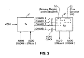
- Transmitter 1' and receiver 2' of Fig. 2 correspond, respectively, to transmitter 1 and receiver 3 of Fig. 1 (but perform auxiliary data encoding, transmission, and decoding functions that are not performed by transmitter 1 and receiver 3 of Fig. 1 ).
- the TMDS link between transmitters 1' and 2' in Fig. 2 is identical to the TMDS link between transmitters 1 and 3 in Fig. 1 , although some of the conductors thereof are shown in Fig. 1 but not in Fig. 2 (for simplicity).
- the Fig. 2 system preferably transmits a video clock over a conductor pair (labeled "Channel C in Fig. 2 ) of the TMDS link, and also transmits a clock for the auxiliary data over at least one channel of the link.
- transmitter 1' transmits video data to receiver 2' over Channels 0, 1, and 2 (which are identical to the identically numbered channels of the Fig.
- Receiver 2' is configured to process the time stamp data to recover the audio clock employed to transmit the audio data.
- the clock for a stream of audio data has a much lower frequency than the pixel clock for a stream of video.
- the audio clock needs to be more accurate than the pixel clock, to reduce jitter. This is true since distortion in analog audio (that has been generated from digital audio data having jitter) is more easily discernible (to one experiencing the analog audio) than is the distortion in a displayed video program generated from digital video having the same amount of jitter.
- each 10-bit code word is decoded back to the original 8-bit word if no errors are present.
- Each code word comprises a 9-bit base pattern (a transition-minimized member of a set of 2 9 nine-bit patterns, whose most significant bit indicates that the base pattern is transition-minimized, concatenated with a tenth bit indicating whether the eight least-significant bits of the base pattern have or have not been inverted in accordance with a DC balancing algorithm).
- each 8-bit source word is first encoded to one of the 9-bit base patterns, and a stream of the 9-bit base patterns are then encoded as a stream of the 10-bit code words (in a manner that achieves improved DC balancing of the transmitted stream of 10-bit code words).
- the decoded video data can include errors (especially when the relevant channel has significant ISI), depending on the specific channel media and the specific data patterns of the transmitted serial bit stream.
- transmitter 1' and receiver 2' were operated to encode and decode the auxiliary data in the same way that they encode and decode the video data, and to send both types of encoded data over the same channel of the serial link, the decoded auxiliary data would be subject to error at the same error rate.
- This error rate can be unacceptably high for auxiliary data (especially when the auxiliary data are audio data), even if it is acceptable for video data.
- transmitter 1' can be configured to encode the auxiliary data in accordance with the invention.
- transmitter 1' can be configured also to encode the video data in accordance with the invention (or to be operable in a mode in which it encodes both the video data and auxiliary data in accordance with the invention).
- transmitter 1' is configured to encode the auxiliary data in accordance with the invention as follows.
- a subset of the full set of 10-bit TMDS code words is selected as the "inventive" code word set such that each transmitted stream of 10-bit words of encoded auxiliary data (consisting only of the inventive code words) has a pattern that is less susceptible to inter-symbol interference than is the pattern determined by a transmitted stream of a TMDS-encoded version of the same data (including not only inventive code words but also members of the full set that are not inventive code words).
- a 2 M -bit subset (where M ⁇ 8) of the full set of 10-bit TMDS code words is selected to be the inventive code word set.
- the inventive code word set also includes one or more code words of the full set that are used as guard band words.
- Receiver 2' is implemented to decode each received one of the inventive 10-bit code words as an auxiliary data word of length M bits.
- Receiver 2' performs the same decoding operations on the encoded auxiliary words received during blanking intervals that it performs on the conventionally encoded video words received during the active video periods.
- transmitter 1' does not perform the conventional DC balancing steps that it performs during its conventional encoding of source video data (in which the eight least significant bits of the "N+1"th encoded video word are inverted, and the resulting nine bits are concatenated with a distinctive tenth, most significant bit when the cumulative DC drift of the N previous encoded video words reaches a predetermined threshold, and otherwise does not invert the eight least significant bits of the "N+1"th encoded video word and instead concatenates the word with another distinctive, tenth, most significant bit).
- transmitter 1' is configured simply to replace each 4-bit source word of auxiliary data with the corresponding one of the inventive code words, regardless of the cumulative DC drift of the resulting stream of inventive code words (and regardless of whether the MSB of the inventive code word is a one or zero).
- inventive code words are preferably chosen so that when the bits of a stream of the inventive code words are transmitted over a serial link as sequence of rising and falling voltage transitions, the bit pattern of such stream of the inventive code words is DC balanced (or is likely to be DC balanced) in the sense that the voltage drift that it determines over time is limited to an acceptable amount.
- transmitter 1' does perform the same DC balancing steps during its encoding of source auxiliary data (using the inventive code words) and during its conventional encoding of source video data. This is taken into consideration in the selection of the inventive code word set.
- each code word of the inventive code word set has a 9-bit base pattern that is a member of a selected subset of the 9-bit base pattern space of the full set of 10-bit TMDS code words, and during encoding of 4-bit words of source auxiliary data (to replace them with the inventive 10-bit code words), the eight least-significant bits of this 9-bit base pattern are either inverted and the resulting pattern concatenated with a tenth (and most significant) bit having a first value, or the base pattern is not inverted and is instead concatenated with a tenth (and most significant) bit having a second value, depending on whether the cumulative DC drift of the stream of previously encoded auxiliary words has reached a predetermined threshold.
- receiver 2' is implemented to perform the same decoding operations on the encoded auxiliary data words received during blanking intervals that it performs on the conventionally encoded video data words received during the active video periods, and then to map each 8-bit word (generated as a result of conventional decoding of one of the 10-bit encoded auxiliary data words) to one of the 2 M auxiliary data words each having M-bit length.
- M i.e., selecting a smaller inventive set of code words from the full set
- BER bit-error rate
- increasing the parameter M results in an increased data rate but at the cost of increased BER.
- This code word set is a subset of the full set of conventional TMDS 10-bit code words, and is useful for encoding 4-bit words of auxiliary data for transmission over a TMDS (or TMDS-like) link over which 8-bit video words (conventionally encoded using the full set of TMDS 10-bit code words) are also transmitted, in cases when it is adequate to transmit the auxiliary data at half the data rate as the video data.
- 8-bit input words of binary auxiliary data are buffered, the four least-significant bits of each are encoded (e.g., in transmitter 1' of Fig.
- each code word is the LSB and (in the case of each 10-bit code word) is the first bit to be transmitted over the serial link.
- the right bit of each code word is the MSB and (in the case of each 10-bit code word) is the last bit to be transmitted over the serial link.
- an input auxiliary data word 10000000 (whose LSB is 1) would be split into two halves (1000 and 0000) and the two halves then encoded as AD1 and AD0, respectively. Then, the 8-bit word AD0 is encoded as the 10-bit inventive word "0011100101” and the 8-bit word AD1 is encoded as the 10-bit inventive word "0110001101.” The two inventive words would then be serialized transmitted over the serial link sequentially, with the bits "0011100101" indicative of the "most significant" half (0000) of the input word being transmitted before the bits "0110001101" that are indicative of the least significant half (1000) of the input word.
- each 10-bit inventive word is decoded into one of the 8-bit words AD0-AD15, and the original 8-bit input auxiliary data words can be reconstructed from the recovered words AD0-AD15 since there is a one-to-one mapping between each word AD0-AD15 and one half (four bits) of each 8-bit input auxiliary data word.
- the input auxiliary data asserted to the transmitter can be 4-bit words, in which case the transmitter would not need to split (or otherwise pack) received input auxiliary data words into 4-bit format before encoding them as a sequence of the words AD0-AD15.
- the input auxiliary data can be pre-encoded as a sequence of 8-bit words AD0-AD15, and the pre-encoded auxiliary data then provided to the transmitter in the form of a sequence of the 8-bit words AD0-AD 15.
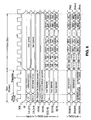
- Figs. 5 and 6 are timing diagrams of signals transmitted during such an embodiment of the invention.
- the upper nine signals of Fig. 5 represent signals input to the transmitter during a blanking interval
- the lower three signals of Fig. 5 represent the auxiliary data (encoded using the 10-bit words of Fig. 4 ) and encoded control and sync signals (to be discussed below) that are transmitted over channels CH0, CH1, and CH2 during the blanking interval in response to the upper nine signals.
- the upper nine signals of Fig. 6 represent signals input to the transmitter at the end of the blanking interval (of Fig. 5 ) and during the active video period that follows such blanking interval
- the lower three signals of Fig. 6 represent the auxiliary data (encoded using the 10-bit words of Fig. 4 ), video data (conventionally encoded), and encoded control and sync signals (to be discussed below) that are transmitted over channels CH0, CH1, and CH2 in response to the upper nine signals.
- auxiliary data periods in a blanking interval (each comprising at least one auxiliary guard band word followed by a burst of a different channel of encoded auxiliary data), an initial auxiliary preamble between the falling edge of DE (at the start of the blanking interval) and the start of the first auxiliary data portion, an additional auxiliary preamble before each subsequent auxiliary data period in the blanking interval, and a video preamble between the last auxiliary data period and the next active video period.
- repetitions of code words indicative of specific patterns of control bits CTL3, CTL2, CTL1, and CTL0 repetitions of code words indicative of any pattern of sync bits HSYNC and VSYNC, and optionally also initial bit patterns (e.g., patterns in the time interval labeled "Rsvd" in Fig. 5 at the start of the initial auxiliary preamble of channels CH2 and CH1) are transmitted.
- initial bit patterns e.g., patterns in the time interval labeled "Rsvd" in Fig. 5 at the start of the initial auxiliary preamble of channels CH2 and CH1
- repetitions of code words indicative of other specific patterns of control bits CTL3, CTL2, CTL1, and CTL0, repetitions of code words indicative of any pattern of sync bits HSYNC and VSYNC, and optionally also initial bit patterns (e.g., patterns in the time interval labeled "Rsvd" in Fig. 6 at the start of the video preamble of channels CH2 and CH1) are transmitted.
- initial bit patterns e.g., patterns in the time interval labeled "Rsvd" in Fig. 6 at the start of the video preamble of channels CH2 and CH1
- code words of specific values of CTL3, CTL2, CTL1, CTL0, VSYNC, and HSYNC are transmitted on channels CH2, CH1, and CH0.
- auxiliary data enable signal can be employed to enable the transmission of each type of auxiliary data (e.g., a signal "AUX1 DE” for auxiliary data of a first type and a signal "AUX2 DE” for auxiliary data of a second type).
- Figs. 5 and 6 have been described with reference to two data enable signals, "DE” and “AUX DE,” it is contemplated that the transmitter can be implemented with a portion (a “core") configured to perform all the described encoding, serialization, and transmission in response to a single data enable signal (e.g., a combined enable signal indicative of the result of performing a logical "OR” operation on the signals DE and AUX DE), and a single set of data inputs (D[23:0]) indicative of either video or auxiliary data.
- a single data enable signal e.g., a combined enable signal indicative of the result of performing a logical "OR” operation on the signals DE and AUX DE
- D[23:0] a single set of data inputs
- Additional circuitry of the transmitter outside the core is configured to receive separate sets of auxiliary data (e.g., 24-bit auxiliary data words) and video data (e.g., 24-bit video data words), and both a video data enable signal DE, and an auxiliary data enable signal "AUX DE.”
- the data enable signals can also occur with other sequences of values, including non-repeating sequences. For example, in some circumstances, auxiliary data are transmitted in some but not all video blanking intervals.
- the additional circuitry of the transmitter can include logic circuitry that "ORs" together the signals DE and AUX DE to produce a combined data enable signal.
- the additional circuitry can also pack the auxiliary data into 4-bit format, encode each 4-bit portion of the auxiliary data as one of the words ADO-ADIS shown in Fig. 4 , add guard band words with appropriate timing into the stream of AD0-AD15 auxiliary data words, and add video guard band words into the stream of video data (or alternatively replace, with appropriate timing, words of the video data with video guard band words).
- the additional circuitry can assert a sequence of bursts of the video data (with video guard band words) and auxiliary data (with guard band words) to the core (e.g., alternating bursts of the video data with video guard band words, and auxiliary data with guard band words), and also assert the combined data enable signal to the core.
- the core performs all the encoding, serialization, and transmission operations described with reference to Figs. 5 and 6 in response to the combined data enable signal (rather than separate DE and AUX DE signals) and the bursts of video and auxiliary data.
- the "additional circuitry" of the transmitter is coupled and configured to receive and encode two or more sets of auxiliary data (each set comprising a different type of auxiliary data).
- the additional circuitry is also coupled and configured to receive a set of video data, an auxiliary data enable signal for each set of auxiliary data (e.g., first and second auxiliary data enable signals "AUX1 DE” and “AUX2 DE”) and a video data enable signal (“DE”), and to assert a sequence of bursts of the video data and bursts of the encoded auxiliary data to the transmitter's core.
- the additional circuitry can include logic circuitry that "ORs" together the signals DE, AUX1 DE, and AUX2 DE to produce a combined data enable signal, and can assert the combined data enable signal (rather than the individual video data enable and auxiliary data enable signals) to the core.
- an appropriate one of the inventive code words is (or two or more appropriate ones of the inventive guard band words are) preferably transmitted (as a guard band word or set of guard band words) at the start of each burst of encoded auxiliary data (i.e., immediately after each "auxiliary preamble" of each blanking interval), at the end of each burst of encoded auxiliary data, and at the start of each burst of encoded video data (i.e., immediately after the "video preamble" of each blanking interval).
- the source data to be transmitted are encoded using a "robust" subset of a full set of code words.
- Each "robust” subset consists of code word sets (sometimes referred to herein as “golden sets”), with each golden set consisting of one or more code words (sometimes referred to herein as “golden words”).
- Each "golden word” of a golden set is indicative of a single source data value (e.g., a source data word). In the case that a golden set consists of two or more golden words, each of these golden words is indicative of the same source data value. Clusters of code words in the full set are determined.
- Each cluster includes a "golden set” and optionally also one or more additional code words of the full set, where each of the additional code words is "similar" to a golden word of the cluster's golden set in the sense that each additional code word is likely to be generated as a result of probable bit errors in transmission, or transmission and decoding, of such golden word.
- Each received code word in one of the clusters is mapped to the source data value determined by the cluster's golden set.
- Each mapping of a cluster of received code words to a single source data value can provide error correction by mapping an error-containing word in the cluster back to the source data value most likely to correspond to the error-containing word.
- the full set of code words can be used to encode one type of data (e.g., video data) for transmission over a channel of a serial link, and the robust subset can be used to encode another type of data (e.g., audio data or other "auxiliary" data related to or useful with video data) for transmission over the same channel.
- one type of data e.g., video data
- the robust subset can be used to encode another type of data (e.g., audio data or other "auxiliary" data related to or useful with video data) for transmission over the same channel.
- each code word in each golden set (and each code word in the full set) is an N-bit word that is an encoded version of an M-bit word, where M is an integer less than N.
- each received N-bit code word can differ from one of the golden words (if a transmission error has occurred) or it can be identical to one of the transmitted golden words.
- Each received N-bit code word in one of the clusters is decoded to generate a decoded M-bit word, and each such decoded M-bit word is mapped to the source data value determined by the cluster's golden set.
- the full set of code words is the set of 10-bit TMDS-encoded words that are indicative of 256 eight-bit source words.
- the robust subset of the full set consists of eight-bit "golden words" indicative of a subset of the full set of 256 eight-bit source words.
- the robust subset consists of sixteen golden sets, each golden set consists of the 10-bit TMDS code words indicative of one eight-bit source word, and each cluster of the 10-bit TMDS code words includes one of the golden sets and at least one 10-bit TMDS code words similar to the code words in such golden set.
- each received 10-bit code word in one of the clusters is decoded in accordance with the TMDS decoding algorithm (or a modified version thereof) to recover an eight-bit word, and each recovered eight-bit word is mapped to the eight-bit source word determined by the cluster.
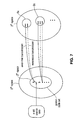
- the full set of code words (which can be used to encode primary data, for example when auxiliary data are encoded in accordance with the invention using only “golden words” of the full set) are those code words (the "2 N space") that can be used to encode 2 N different source data words, each source data word being an ordered set of N bits.
- the golden words (the "2 n space") are a subset of the code words of the full set that can be used to encode 2 n different source data words, each such source data word being an ordered set of "n” bits (where "n” is an integer less than N).
- raw source data (which can consist of words of any length) can be buffered and packed into an n-bit format (i.e., into n-bit members of a set of 2 n source data words).
- n-bit format i.e., into n-bit members of a set of 2 n source data words.
- Each different n-bit source data word can then be encoded as one of the golden words (in the "2" space") and transmitted over a serial link (typically over a single channel of the link).
- the transmission can result in error or it can be error free.
- Clusters of the full set of code words are predetermined such that each cluster includes a "golden set” (of one or more of the golden words) and optionally also one or more additional code words of the full set, where each of the additional code words is similar to a golden word of the cluster's golden set.
- cluster "S a” includes the golden set consisting of each of the golden words that encodes source word "a”
- cluster "S b” includes the golden set consisting of each of the golden words that encodes source word "b”).
- Each received code word in one of the clusters is mapped to the source data value determined by the cluster's golden set.
- each code word of the 2 N space is a 10-bit TMDS-encoded word
- the 2 n space is a subset of the full set of 10-bit TMDS-encoded words.
- Each transmitted 10-bit TMDS code word is decoded in accordance with the TMDS decoding algorithm (or a modified version thereof) to generate an 8-bit code word.
- the transmission of golden words (and any decoding thereof) can result in error or can be error free.
- the cluster containing such golden word preferably includes all the N-bit members of the 2 n space likely to result from occurrence of such a transmission error during transmission of the golden word.
- the clusters are disjoint, an N-bit word included in one cluster is omitted from all the other clusters.
- Each embodiment of the invention employs at least one (and typically more than one) cluster that contains at least one code in addition to each golden word of a golden set. Some embodiments of the invention employ at least one cluster that contains at least one code in addition to each golden word of a golden set, and also at least one other cluster that contains no code other than each golden word of a golden set. Since all the clusters (e.g., S a , S b , etc. of Fig. 7 ) are mutually disjoint, then regardless of whether or not an error occurs during transmission (or transmission and decoding), if a cluster contains a received N-bit code, the received code is mapped back to the correct source word.
- all the clusters e.g., S a , S b , etc. of Fig. 7
- the full set of code words (the "2 N space") is the full set of 10-bit TMDS code words, and the "2" space” consists of those TMDS code words that are indicative of a predetermined set of 16 different 8-bit source data words.
- each cluster includes a golden set of the TMDS code words including golden words indicative of one of the 16 different source data words.
- 4-bit words of raw source data are preliminarily encoded as the 16 different 8-bit source data words, and each resulting 8-bit source data word is then encoded as one of the 10-bit members of the 2" space for transmission.
- the robust subset (of the full set of TMDS code words) consists of those 10-bit TMDS code words that (when decoded in accordance with the TMDS decoding algorithm or a modified version thereof) determine the 16 predetermined 8-bit source data words (of the 256 eight-bit source data words determined by the full set of TMDS code words).
- Each cluster preferably includes not only the golden words of a golden set, but also at least one 10-bit TMDS code word "similar" to one of the golden words in the sense that it is more likely to result from bit errors in transmission of the golden word than are other TMDS code words (e.g., the code word "similar" to the golden word may differ from the golden word only in the value of one of its bits).
- the process of selecting the golden sets from the full set of code words is very important.
- the best choice for the specific golden sets selected from a full set of binary code words depends on the particular coding implemented by the full set (i.e., the details of which bits of each code word in the full set are zeroes and which are ones).
- the code words of the golden sets are selected to be those whose serial patterns (during transmission) have fewer contiguous zeros and ones (e.g., on the average), and thus are less susceptible to ISI during transmission, than do those code words in the full set that are not selected (e.g., the average number of contiguous zeros and ones, per code word, of the golden words is less than the average number of contiguous zeros and ones, per code word, of the code words in the full set that are not selected as golden words).
- the golden words are selected to be those satisfying the criterion that the Hamming distance between any golden word in one cluster and any golden word in any other cluster exceeds a threshold, or the criterion that the Hamming distance between golden words in different clusters is maximized (in some sense) to the extent practical (e.g., the criterion that an average Hamming distance between golden words in different clusters is maximized) subject to the constraint that the clusters are mutually disjoint.
- This helps to increase the number of "errored codes" (codes other than golden codes of one golden set) that can be included in each cluster, while keeping the constraint that the clusters are mutually disjoint.
- the receiver e.g., receiver 2' of Fig. 2
- the receiver is preferably configured to include a predetermined table that outputs one value (e.g., a source data word) determined by each cluster in response to each input indicative of an element of the cluster (e.g., in response to each of four received code words, where the cluster consists of one golden word and three code words similar to the golden word).
- one value e.g., a source data word
- the table implements a mapping of each received code word in each cluster to the source word determined by the cluster's golden set, or of each received code word in each cluster to a golden word of the cluster's golden set (which is then mapped by conventional hardware or software in (or external to) the receiver to a source word determined by the cluster's golden set), or of a decoded version of each received code word in each cluster to a source word determined by the cluster's golden set, or of a decoded version of each received code word in each cluster to a single decoded code word (which is then mapped by conventional hardware or software in, or external to, the receiver to a source word determined by the cluster's golden set).
- receiver 2' of Fig. 2 includes "code word recovery, mapping, and decoding" circuitry 20, which implements such a table.
- Circuitry 20 is configured to recover 10-bit TMDS code words from the data received on each of Channel 0, Channel 1, and Channel 2, to map each recovered word in one of the clusters to a golden word of the cluster (using the table), to decode each golden word to generate an 8-bit decoded value (one of the seventeen 8-bit words in the left column of Fig. 4 ).
- the 8-bit decoded values are indicative of source words, and circuitry 20 optionally generates a 4-bit raw source data word in response to each 8-bit word that is indicative of one of the words AD-0-AD15 in Fig. 4 ).
- the clusters can be a partition of the full set of code words (e.g., the 2 N space of Fig. 7 ), so that the union of the clusters covers the whole space of code words (e.g., the entire 2 N space of Fig. 7 ) and the clusters are mutually disjoint.
- the union of the clusters does not cover the whole space of code words (e.g., the entire 2 N space of Fig. 7 ).
- a first cluster includes a first golden word
- a second cluster includes a second golden word
- a received code word that is not a golden word
- P1 probability to result from transmission of the first golden word
- P2 probability to result from transmission of the second golden word
- some implementations of the inventive receiver are configured to perform a two-stage mapping of received versions of the golden words to source data values: a first stage in which each received code word in a cluster is mapped to a golden word of the cluster's golden set; and a second stage in which the golden words determined during the first stage is mapped to the source word determined by the cluster's golden set.
- an additional block of error correction code is transmitted with each set of golden words, and the receiver is configured to perform the first stage of mapping before performing error correction using the error correction code (to correct error-containing received code words that are not members of any of the clusters, to replace them with golden words to the extent possible).
- the inventive golden words and clusters are preferably chosen so as to implement mappings that exploit the degree of freedom provided by the performance of error correction.
- the golden words can be selected to satisfy the criteria that the Hamming distance between any two golden words in different clusters is minimized to the extent practical (or otherwise not maximized), and that the clusters are mutually disjoint. With clusters including such golden words, the number of erroneous bits detected by the error correction circuitry in the receiver can be minimized and hence, the overhead of the error correction code can be minimized.
- an implementation of receiver 2' of Fig. 2 includes error correction circuitry 22 coupled to an output of "code word recovery, mapping, and decoding" circuitry 20.
- Circuitry 20 is configured to perform a first stage of mapping to generate golden words in response to recovered code words that are members of the inventive clusters, and to assert (to circuitry 22) the error correction code and any 10-bit code words received over the link that are not members of any cluster.
- Circuitry 22 performs error correction using the error correction code to correct error-containing received code words that are not members of any of the clusters, thereby replacing such error-containing code words with golden words to the extent possible.
- Circuitry 20 is optionally also configured to decode the golden words that it receives or generates. The golden words generated by circuitry 22 can be asserted to circuitry 20 for decoding, or can be decoded by other decoding circuitry within receiver 2'. In variations on the described implementation of receiver 2', circuitry 22 is omitted.
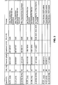
- a set of seventeen golden words and a set of code word clusters (each including one of the golden words) employed in a class of preferred embodiments of the invention.
- the third column shows the seventeen golden words, which have been described above.
- Sixteen of the golden words are used to encode sixteen different 8-bit source data words (each 8-bit source data word being indicative of four bits of raw source data), and the other golden word (the word "1100110010" in the first row) is used only as a guard band word.
- Each of the golden words is a 10-bit TMDS encoded word.
- the fourth column shows some possible error cases for each 10-bit golden word
- the fifth column shows the 8-bit word resulting from decoding of the corresponding 10-bit word in the fourth column in accordance with the conventional TMDS decoding algorithm
- the sixth column simply shows the hexadecimal representations of the corresponding elements in the fifth column.
- the seventh column includes an indication as to whether each corresponding word in the fourth column is or is not a member of the cluster containing the corresponding golden word in the third column. Specifically, the term "IGNORE" in the seventh column indicates that the corresponding word in the fourth column is not a member of the cluster that contains the corresponding golden word in the third column.
- clusters there are seventeen clusters (separated by the horizontal bars in Fig. 4 ): a first cluster including the golden word "1100110010” and the code words “1110110010” and “1100010010” (all mapped to the "pre-data” auxiliary guard band word “01010101”); a second cluster (for encoding the source word AD0) including the golden word “0011100101” and the code words “1011100101,” "0001100101,” "0011110101,”and “0011100001” (all mapped to the source word AD0); a third cluster (for encoding the source word AD1) including the golden word "0110001101” and the code words "0111001101” and "0110000101” (all mapped to the source word AD1); and the fourteen other indicated clusters (each including a different one of the fourteen other golden words, and consisting of words mapped to a different one of the source words AD2-AD15).
- the receiver When the receiver recovers a code word (in the fourth column of Fig. 4 ) in one of the indicated clusters (there will be no "IGNORE" symbol in the seventh column corresponding to such recovered code word), the receiver will map the recovered code word to the source word (in the first column of Fig. 4 ) determined by the cluster's golden word (which is equivalent to mapping the recovered code word to the cluster's golden word in the third column).
- Those code words in the fourth column marked with the term "IGNORE” in the seventh column are not members of the cluster that contains the corresponding golden word.
- the code word "1100111010" in the third row of Fig. 4 is not a member of the first cluster (containing golden word "1100110010") because this code word is a member of the cluster that contains golden word "1000111010” and the clusters should be disjoint.
- the receiver would recover code word "1100111010” as a result of a single bit error (having relatively high probability) in transmission of golden word "1100110010" (in the first row of Fig.
- the receiver would map the received word to 8-bit source word "AD10" (which is equivalent to mapping the received word to the golden word "1000111010”) rather than mapping to the source word ("01010101") determined by golden word "1100110010.”
- the receiver when the transmitter transmits the golden word "1100110010" (in the first row of Fig. 4 ), the receiver would recover the code word "1100110010” if the transmission is error-free (which has very high probability). The receiver would decode this recovered word in accordance with the conventional TMDS-decoding algorithm to determine decoded 8-bit word "01010101” and map the decoded 8-bit word to the source word "01010101" (which is the pre-data auxiliary guard band word). The receiver would recover the word "0011001111” (in the 52 nd row of Fig.
- each guard band word can be a golden word (as in the Fig. 4 example) in which case there can be a cluster for each guard band word, each such cluster containing two or more code words (including a guard band word).
- the guard words are not golden words but they are reliably distinguishable from the golden words.
- each guard band word should have a bit pattern which allows the receiver to more reliably identify the relevant transition (indicated by the guard band word or words) between encoded control (or sync) word transmission and encoded data transmission.
- the golden set should includes appropriate guard band words (i.e., the guard band words are golden words), or each golden word of the golden set should be reliably distinguishable from each guard band word to be employed.
- the set of 17 golden words shown in Fig. 4 includes a special auxiliary guard band word (having bit pattern "1100110010,” and shown in the third column of the first row of Fig.
- auxiliary guard band word two repetitions of this "pre-data" auxiliary guard band word are preferably transmitted at the start of each burst of encoded auxiliary data (i.e., just after each auxiliary preamble) in each of channels CH2 and CH1. Since the last bit of each specific encoded control word transmitted in channels CH2 and CH1 (during the auxiliary preamble) is "0" as explained above, the first transmitted bit of the code word chosen as the pre-data auxiliary guard band word is "1" to increase the reliability with which the receiver can identify the start of a transmitted burst of auxiliary data.
- the set of 17 golden words shown in Fig. 4 also includes a word (the golden word "0011001101" that corresponds to input word AD11) that is used to identify the end of an auxiliary data burst, and is also used as a video guard band word.
- a word the golden word "0011001101" that corresponds to input word AD11
- two repetitions of this "post-data" auxiliary guard band word are preferably transmitted at the end of each burst of encoded auxiliary data (i.e., just before each video preamble) in each of channels CH2 and CH1.
- the pre-data auxiliary guard band word need not be repeated (transmitted twice) at the start of each auxiliary data burst, and the post-data auxiliary guard band word need not be repeated at the end of each auxiliary data burst.
- each is repeated in order to allow the receiver more easily to recognize and correct for data shift errors between channels that can occur during transmission and recovery of the data (e.g., error in the trace length of the received data on channel CH1 relative to that of the data received on channel CH2).
- an auxiliary guard band word is repeated more than twice (or is transmitted only once) at the start of each auxiliary data burst and/or more than twice (or is transmitted only once) at the end of each auxiliary data burst.
- the golden word "0011001101" (that corresponds to input word AD11) is used as a video guard band word to identify the start of a video data burst, in addition to being used as a code word for encoding the four-bit quantity of auxiliary data indicated by input word AD11, and as a post-data auxiliary guard band word.
- two repetitions of this video guard band word are preferably transmitted at the start of each burst of encoded video data (i.e., just after each video preamble).
- the last two bits of the encoded control or sync word transmitted in each of channels CH1 and CH2 are likely to be "11" as explained above, the first two transmitted bits of the video guard band word are chosen to be "00" to increase the reliability with which the receiver can identify the start of a transmitted burst of video data.
- the video guard band word need not be repeated (transmitted twice) at the start of each video data burst. In the preferred embodiment shown in Fig. 6 , it is repeated in order to ensure transmission (on each of channels CH0, CH1, and CH2) of code words indicative of an even number of pixels during the burst. In other embodiments, a video guard band word is repeated more than twice (or is transmitted only once) at the start of each video data burst.
- two (or more than two) streams of video data are transmitted (over one, two, or more than two channels).
- two or more streams of video data can be transmitted in time-multiplexed fashion over each of one or more of Channels 0, 1, and 2 of Fig. 2 .
- different video guard band words can be transmitted at the start (and/or the end) of each burst, with each different stream being identified by a different video guard band word.
- two (or more than two) streams of auxiliary data can be transmitted over one, two, or more than two channels). If bursts of different streams of auxiliary data are sequentially transmitted over one channel, different auxiliary guard band words can be transmitted at the start (and/or the end) of each burst, with each different stream being identified by a different guard band word.
- DE shifts in individual channels can be corrected independently (in accordance with the invention) by using guard band words in each channel. Since there can be misalignment between the DE transitions indicated by the bits transmitted over multiple channels of a TMDS link (or TMDS-like link or other serial link) by one pixel clock cycle (or more than one pixel clock cycle) in either direction (due to ISI or other noise sources on the link), a set of identical guard band words (each a member of the set of inventive code words) is preferably transmitted in accordance with the invention at the start and/or end of each burst of data encoded using the inventive code words that is transmitted over each channel (e.g., at the end of each auxiliary preamble of each channel, and/or at the start of the video preamble of each channel, and/or at the end of the video preamble of each channel). This can improve the channel-to-channel alignment and data integrity. The need to have available the appropriate number of guard band words is a factor
- the purpose of repeating the transmission of a guard band word is to prevent two types of misidentification of transitions: identifying the transition too early and identifying the transition too late.
- the invention prevents such pixel shift errors up to N pixels in either direction.
- the invention ensures that when there is an N pixel shift to the left, the last data value is not lost (only the post-data guard band word is lost).
- a sequence of only N post-data guard band words is needed for use with a sequence of N pre-data guard band words.
- the auxiliary guard band words transmitted at the start and end of each auxiliary data burst on channels CH2 and CH1 are not transmitted at the start and end of each auxiliary data burst on channel CH0. Rather, special encoding is used to determine the first two and last two 10-bit inventive code words transmitted in each auxiliary data burst on channel CH0.
- each of the first two input auxiliary data packets to be encoded and the last two input auxiliary data packets to be encoded comprises two bits (whereas all the other packet comprise four bits as described above).
- the first 2-bit input auxiliary packet is encoded as one of the words AD0, AD1, AD2, and AD3 in Fig.
- the second 2-bit input auxiliary packet is encoded as another one of the words AD0, AD1, AD2, and AD3.
- the first two 10-bit words transmitted in the burst are versions of the inventive code word indicative of these two words AD0, AD1, AD2, and AD3 (and are thus indicative of the first four bits of input auxiliary data).
- the second-last 2-bit input auxiliary packet is encoded as one of the words AD0, AD1, AD2, and AD3 in Fig. 4 and the last 2-bit input auxiliary packet is encoded as another one of the words AD0, AD1, AD2, and AD3.
- the last two 10-bit words transmitted in the burst are versions of the inventive code word indicative of these two words AD0, AD1, AD2, and AD3 (and are thus indicative of the last four bits of input auxiliary data).
- control or synchronization bits can produce different errors on video (or auxiliary) data bits that are transmitted just after the control characters, when ISI is present on the serial data transmission channel. This is preferably recognized and used as a factor in selecting the inventive code word set for use in transmitting the video (or auxiliary) data.
- the control codes sent just before the data are controlled to reduce the ISI effect.
- bursts of encoded auxiliary data and bursts of encoded video data are transmitted over a serial link (which need not be a TMDS link), and the auxiliary data are encoded in accordance with the invention using a set of inventive code words.
- the set of inventive code words includes a "video" guard band word that is transmitted at the start of each encoded video data burst, and an "auxiliary" guard band word that is transmitted at the start of each encoded auxiliary data burst.
- the video guard band word is also used for a second purpose: to encode auxiliary data.
- a video guard band word is transmitted at the start of each active video period.
- Each blanking interval comprises an "auxiliary" preamble period (between the falling edge of the video data enable signal and the start of a burst of auxiliary data) in which control (or sync) signals of a specific type are transmitted, at least one auxiliary data period after the auxiliary preamble period (each auxiliary data period comprising an auxiliary guard band word followed by a burst of encoded auxiliary data), and a "video" preamble period between the last auxiliary data period and the next active video period.
- guard band words in accordance with the invention is to guarantee that the receiver can recognize the transition between the first guard band word transmitted at the start of an encoded data burst and the last bit transmitted before such guard band word, and between the last guard band word transmitted at the end of an encoded data burst and the first bit transmitted after such guard band word.
- a conventional encoding algorithm is used to encode primary data (which can but need not be video data) for transmission in bursts over a serial link
- auxiliary data e.g., audio data or data of another type that can be transmitted with a lower data rate than the primary data
- the full set of code words used for encoding the primary data has at least one code word for each of 2 N different words of the primary data (sometimes referred to as source data words).
- the inventive subset of such full set has at least one code word for each of not more than 2 M different words (where M ⁇ N) of the auxiliary data (also referred to sometimes as source data words).
- the auxiliary data are buffered and packed into M-bit format (i.e., into words each consisting of M bits).
- M-bit format i.e., into words each consisting of M bits.
- Each possible value of the M-bit source data has a preselected code in the 2 M word space provided by the inventive code words.
- the M-bit words of auxiliary data are mapped to inventive code words in the 2 M word space which are then transmitted over the link.
- the inventive golden words to employ to transmit encoded data e.g. auxiliary data distinct from video data
- the DC balancing bits and transition control bits e.g., bits Q[9] and Q[8]
- Any bit error occurring during processing of the DC balancing and transition control bits can affect other bits of the multi-bit encoded words.
- a one-bit error in one of the critical bits is translated into a burst error. This effect is preferably considered in selecting the inventive code words from a full set of TMDS-encoded words.
Claims (74)
- Système de transmission englobant:un récepteur (2') ;un émetteur (1') ; etune liaison série entre l'émetteur (1') et le récepteur (2'), le récepteur étant configuré pour recevoir des données d'entrée, configuré pour encoder les données d'entrée en mots codés à partir d'un jeu de mots codés et configuré pour transmettre les mots codés au récepteur (2') via la liaison série ;caractérisé en ce que :les données d'entrée englobent des données vidéo et des données auxiliaires, et en ce quea) l'émetteur (1') est configuré pour générer une séquence conventionnelle de mots codés vidéo en encodant les données vidéo, chacun des mots codés vidéo étant un membre du jeu complet de mots codés ;b) l'émetteur (1') est configuré pour encoder les données auxiliaires sous la forme d'une séquence de mots codés sélectionnés, chacun des mots codés sélectionnés étant un membre d'un sous-groupe de mots préférés du jeu complet de mots codés, de telle sorte que la séquence de mots codés sélectionnés est moins sensible à un brouillage intersymbole au cours de la transmission via la liaison que la séquence conventionnelle de mots codés,c) le récepteur (2') est configuré pour des données auxiliaires encodées en regroupant les mots codés du jeu complet de mots codés en grappes disjointes de mots codés, dans lequel- les mots codés du jeu complet qui sont des mots qui ne sont pas préférés sont des mots non préférés ;- chacun des mots préférés est le signe d'une valeur de données auxiliaires ;- chacune des grappes englobe un jeu de mots préférés constitué par au moins un des mots préférés, au moins une des grappes englobant au moins un des mots non préférés;- chacun desdits jeux de mots préférés est le signe d'une valeur différente de données auxiliaires ; et- le récepteur (2') est configuré pour procéder au mappage de chaque mot codé reçu qui est membre d'une des grappes afin d'obtenir la valeur de données auxiliaires déterminée par le jeu de mots préférés de ladite grappe.
- Système selon la revendication 1, dans lequel chacune desdites grappes englobe au moins un des mots non préférés qui est susceptible d'être généré suite à au moins une erreur sur les bits lors de la transmission, ou bien lors de la transmission et du décodage, du mot préféré de la grappe.
- Système selon la revendication 1, dans lequel chacun desdits jeux de mots préférés est constitué par un et un seul mot préféré.
- Système selon la revendication 3, dans lequel chacune desdites grappes englobe également au moins un des mots non préférés qui est susceptible d'être généré suite à au moins une erreur sur les bits lors de la transmission, ou bien lors de la transmission et du décodage, du mot préféré de la grappe.
- Système selon la revendication 1, dans lequel les mots préférés répondent au critère tel que la distance de Hamming entre n'importe quel mot préféré dans une quelconque grappe et l'un quelconque des mots préférés dans une quelconque autre grappe dépasse un seuil.
- Système selon la revendication 1, dans lequel lesdits mots préférés répondent au critère tel que la distance de Hamming entre les mots préférés dans différentes grappes est maximisée dans la mesure possible en pratique.
- Système selon la revendication 1, dans lequel l'émetteur est configuré pour transmettre des blocs codés de correction d'erreurs de transmission via la liaison série avec la séquence de mots codés sélectionnés, et dans lequel le récepteur englobe également :un ensemble de circuits de correction d'erreurs configurés pour exécuter une correction d'erreurs, en utilisant les blocs codés de correction d'erreurs, sur au moins un certain nombre des mots codés reçus qui ne sont pas des membres d'une quelconque grappe, les mots préférés répondant au critère tel que la distance de Hamming entre les mots préférés dans différentes grappes est maximisée dans la mesure possible en pratique.
- Système selon la revendication 1, dans lequel chaque mot codé reçu qui représente un mot non préféré d'une des grappes est un mot contenant une erreur et le récepteur (2') est configuré pour exécuter une correction d'erreurs en soumettant à un mappage chacun desdits mots contenant une erreur pour obtenir la valeur de données d'entrée déterminée par le jeu de mots préférés de ladite grappe.
- Système selon la revendication 1, dans lequel l'émetteur (1') est configuré pour générer une séquence de mots codés vidéo en encodant les données vidéo, et l'émetteur (1') est configuré pour transmettre au récepteur (2') via la liaison série, une première rafale des mots codés vidéo suivie d'une rafale des mots codés sélectionnés suivie d'une deuxième rafale des mots codés vidéo, chacun des mots codés vidéo étant un membre du jeu complet de mots codés et au moins un des mots codés vidéo n'étant pas un membre du sous-groupe du jeu complet.
- Système selon la revendication 9, dans lequel l'émetteur (1') est également couplé pour recevoir des bits de commande, configuré pour générer des rafales de mots de commande encodés par encodage des bits de commande, et configuré pour transmettre, au récepteur via la liaison série, une première rafale des mots de commande encodés entre la première rafale des mots codés vidéo et la rafale des mots codés sélectionnés et une deuxième rafale des mots de commande encodés entre la rafale des mots codés sélectionnés et la deuxième rafale des mots codés vidéo.
- Système selon la revendication 10, dans lequel les mots codés sélectionnés englobent au moins un mot de bande de garde, la rafale des mots codés sélectionnés possède un mot initial et le mot initial est le mot de bande de garde.
- Système selon la revendication 10, dans lequel les mots codés sélectionnés englobent au moins un mot de bande de garde, la rafale des mots codés sélectionnés possède un jeu initial de mots et chaque mot du jeu initial de mots est ledit mot de bande de garde.
- Système selon la revendication 10, dans lequel les mots codés sélectionnés englobent au moins un mot de bande de garde, la rafale des mots codés sélectionnés possède un mot final et le mot final est le mot de bande de garde.
- Système selon la revendication 10, dans lequel les mots codés sélectionnés englobent au moins un mot de bande de garde, la rafale des mots codés sélectionnés possède un jeu final de mots et chaque mot du jeu final de mots est ledit mot de bande de garde.
- Système selon la revendication 10, dans lequel la liaison série est une liaison TMDS et les mots codés sélectionnés sont constitués par dix-sept mots codés TMDS différents à transition minimisée, englobant au moins un mot codé TMDS à transition minimisée utilisé comme mot de bande de garde.
- Système selon la revendication 10, dans lequel les mots codés sélectionnés englobent au moins deux mots de bande de garde, englobant un premier mot de bande de garde et un deuxième mot de bande de garde, la deuxième rafale des mots codés vidéo possède un mot initial, le mot initial de la deuxième rafale des mots codés vidéo est le premier mot de bande de garde, la rafale de mots codés sélectionnés possède un mot initial, et le mot initial de la rafale des mots codés sélectionnés est le deuxième mode de bande de garde.
- Système selon la revendication 16, dans lequel la liaison série est une liaison TMDS et les mots codés sélectionnés sont constitués par dix-sept mots codés TMDS différents à transition minimisée, englobant au moins un mot codé TMDS à transition minimisée utilisé uniquement pour faire office dudit deuxième mot de bande de garde et un autre mot codé TMDS à transition minimisée utilisé pour faire office dudit premier mot de bande de garde et également utilisé à titre d'un des mots codés sélectionnés dans ladite rafale des mots codés sélectionnés.
- Système selon la revendication 1, dans lequel l'émetteur (1') est configuré pour générer une séquence de mots codés vidéo en encodant les données vidéo, et l'émetteur (1') est configuré pour transmettre au récepteur (2') via la liaison série, une première rafale des mots codés vidéo suivie d'une rafale des mots codés sélectionnés suivie d'au moins deux rafales des mots codés sélectionnés, suivies par une deuxième rafale des mots codés vidéo, chacun des mots codés vidéo étant un membre du jeu complet de mots codés et au moins un des mots codés vidéo n'étant pas un membre du sous-groupe du jeu complet.
- Système selon la revendication 18, dans lequel l'émetteur (1') est également couplé pour recevoir des bits de commande, configuré pour générer des rafales de mots de commande encodés par encodage des bits de commande, et configuré pour transmettre, au récepteur (2'), via la liaison série, une première rafale des mots de commande encodés entre la première rafale des mots codés vidéo et les rafales des mots codés sélectionnés et une deuxième rafale des mots de commande encodés entre les rafales des mots codés sélectionnés et la deuxième rafale des mots codés vidéo.
- Système selon la revendication 19, dans lequel les mots codés sélectionnés englobent au moins un mot de bande de garde, une première rafale des mots codés sélectionnés possède un mot initial et le mot initial est le mot de bande de garde.
- Système selon la revendication 19, dans lequel les mots codés sélectionnés englobent au moins un mot de bande de garde, une première rafale des mots codés sélectionnés possède un jeu initial de mots et chaque mot du jeu initial de mots est ledit mot de bande de garde.
- Système selon la revendication 1, dans lequel la liaison série est une liaison TMDS.
- Système selon la revendication 22, dans lequel les mots codés sélectionnés sont constitués par dix-sept mots codés TMDS différents à transition minimisée, englobant au moins un mot codé TMDS utilisé uniquement comme mot de bande de garde.
- Système selon la revendication 22, dans lequel les mots codés sélectionnés sont constitués par dix-sept mots codés TMDS différents à transition minimisée, englobant au moins un mot codé TMDS à transition minimisée utilisé uniquement comme mot de bande de garde.
- Système selon la revendication 1, dans lequel chacun des mots codés sélectionnés est un mot binaire de L bits et au moins un sous-groupe respectif des mots codés sélectionnés est le signe d'un mot de M bits des données d'entrée, M étant inférieur à L.
- Système selon la revendication 25, dans lequel L = 10 et M = 4.
- Système selon la revendication 25, dans lequel l'émetteur (1') est couplé pour recevoir des mots source des données d'entrée, chacun des mots source comprenant N bits, N étant inférieur à L et N étant supérieur à M, et l'émetteur (1') est configuré pour condenser les mots source pour obtenir des mots de M bits des données d'entrée et pour encoder chacun des mots de M bits des données d'entrée pour faire office d'un des mots codés sélectionnés.
- Système selon la revendication 1, dans lequel chacun des mots codés sélectionnés est un mot binaire de L bits, un premier sous-groupe des mots codés sélectionnés est le signe d'un mot de M bits des données d'entrée, M étant inférieur à L, et un deuxième sous-groupe des mots codés sélectionnés est le signe d'un mot de N bits des données d'entrée, N étant inférieur à M.
- Système selon la revendication 28, dans lequel L = 10, M = 4 et N = 2.
- Système selon la revendication 1, dans lequel le jeu complet de mots codés est un jeu de mots codés TMDS de 10 bits, à transition minimisée.
- Système selon la revendication 1, dans lequel chacun des mots codés sélectionnés est le signe d'une séquence de L bits binaires, et les mots préférés possèdent un nombre de bits « zéro » contigus et de bits « uns» contigus par mot codé en moyenne inférieur à celui des mots non préférés du jeu complet.
- Système selon la revendication 1, dans lequel chacun des mots codés sélectionnés est le signe d'une séquence différente de bits binaires, l'émetteur (1') est configuré pour transmettre la séquence de mots codés sélectionnés au récepteur (2') via la liaison série sous la forme d'une séquence de transitions de tensions montantes et descendantes, et les mots codés sélectionnés possèdent des profils binaires qui mettent en oeuvre un équilibrage en courant continu en limitant le décalage de tension de la liaison série au cours de la transmission de ladite séquence de mots codés sélectionnés à une valeur prédéterminée.
- Récepteur (2') destiné à recevoir des mots codés émis résultant d'une transmission, via une liaison série, des mots codés à partir d'un jeu de mots codés et désignant des données d'entrée, ledit récepteur (2') englobant:au moins une entrée configurée pour s'accoupler à la liaison afin de recevoir les mots codés émis ; etun ensemble de circuits, accouplé à l'entrée ;caractérisé en ce que
les données d'entrée englobent des données auxiliaires et des données vidéo, et en ce que
le récepteur (2') est configuré pour recevoir les données vidéo sous la forme d'une séquence conventionnelle de mots codés vidéo, chacun des mots codés vidéo étant un membre du jeu complet de mots codés ; et
le récepteur (2') est configuré pour recevoir les données auxiliaires sous la forme d'une séquence de mots codés sélectionnés, chacun des mots codés sélectionnés étant un membre d'un sous-groupe de mots préférés du jeu complet de mots codés, de telle sorte que la séquence de mots codés sélectionnés est moins sensible à un brouillage intersymbole au cours de la transmission via la liaison que la séquence conventionnelle de mots codés, et
l'ensemble de circuits est configuré pour corriger des erreurs de transmission des données auxiliaires encodées en regroupant des mots codés du jeu complet de mots codés pour obtenir des grappes disjointes des mots codés; dans lequel- les mots codés du jeu complet qui sont des mots qui ne sont pas préférés sont des mots non préférés ;- chacun des mots préférés est le signe d'une valeur de données auxiliaires ;- chacune des grappes englobe un jeu de mots préférés constitué par au moins un des mots préférés, au moins une des grappes englobant au moins un des mots non préférés ;- chacun desdits jeux de mots préférés est le signe d'une valeur différente de données auxiliaires ; et- ledit ensemble de circuits est configuré pour procéder au mappage de chaque mot codé reçu qui est membre d'une des grappes afin d'obtenir la valeur de données auxiliaires déterminée par le jeu de mots préférés de ladite grappe. - Récepteur selon la revendication 33, dans lequel les mots préférés répondent au critère tel que la distance de Hamming entre n'importe quel mot préféré dans une quelconque grappe et l'un quelconque des mots préférés dans une quelconque autre grappe dépasse un seuil.
- Récepteur selon la revendication 33, dans lequel, lesdits mots préférés répondent au critère tel que la distance de Hamming entre les mots préférés dans différentes grappes est maximisée dans la mesure possible en pratique.
- Récepteur selon la revendication 33, dans lequel des blocs codés de correction d'erreurs de transmission sont transmis avec les mots codés émis, et le récepteur englobe également:un ensemble de circuits de correction d'erreurs configurés pour exécuter une correction d'erreurs, en utilisant les blocs codés de correction d'erreurs, sur au moins un certain nombre des mots codés reçus qui ne sont pas des membres d'une quelconque grappe, les mots préférés répondant au critère tel que la distance de Hamming entre les mots préférés dans différentes grappes est maximisée dans la mesure possible en pratique.
- Récepteur selon la revendication 33, dans lequel la liaison série est une liaison TMDS et les mots codés émis sont des mots codés TMDS de 10 bits, à transition minimisée.
- Récepteur selon la revendication 33, dans lequel la liaison série est une liaison TMDS et les mots codés préférés sont constitués par dix-sept mots codés TMDS différents, englobant au moins un mot codé TMDS utilisé uniquement comme mot de bande de garde.
- Récepteur selon la revendication 38, dans lequel les mots codés sélectionnés sont constitués par dix-sept mots codés TMDS différents à transition minimisée, englobant au moins un mot codé TMDS à transition minimisée utilisé uniquement comme mot de bande de garde.
- Récepteur selon la revendication 33, dans lequel chacun des mots codés sélectionnés est un mot binaire de L bits.
- Récepteur selon la revendication 33, dans lequel chacun des mots codés sélectionnés est un mot binaire de L bits et au moins un sous-groupe respectif des mots codés sélectionnés est le signe d'un mot de M bits des données d'entrée, M étant inférieur à L.
- Récepteur selon la revendication 40, dans lequel L = 10 et M = 4.
- Émetteur selon la revendication 33, dans lequel chacun des mots codés sélectionnés est un mot binaire à L bits, un premier sous-groupe des mots codés sélectionnés est le signe d'un mot à M bits des données d'entrée, M étant inférieur à L, et un deuxième sous-groupe des mots codés sélectionnés est le signe d'un mot à N bits des données d'entrée, N étant inférieur à M.
- Émetteur selon la revendication 33, dans lequel L = 10, M = 4 et N = 2.
- Émetteur selon la revendication 33, dans lequel chacun des mots codés sélectionnés est le signe d'une séquence de L bits binaires, et les mots préférés possèdent un nombre de bits « zéro » contigus et de bits « uns » contigus par mot en moyenne inférieur à ceux des mots non préférés du jeu complet.
- Procédé pour transmettre des données encodées Via une liaison série, ledit procédé englobant les étapes consistant à :(a) transmettre des mots codés d'un jeu de mots codés via la liaison, les mots codés désignant des mots de données d'entrée ;(b) recevoir les modes codées transmis résultant de la transmission des mots codés via la liaison ;
caractérisé en ce que :les données d'entrée englobent des données vidéo et des données auxiliaires, et en ce que :les mots codés reçus sont le signe de données vidéo sous la forme d'une séquence conventionnelle de mots codés vidéo, chacun des mots codés vidéo étant un membre du jeu complet de mots codés ; et en ce queles mots codés reçus désignent des données auxiliaires sous la forme d'une séquence de mots codés sélectionnés, chacun des mots codés sélectionnés étant un membre d'un sous-groupe de mots préférés du jeu complet de mots codés, de telle sorte que la séquence de mots codés sélectionnés est moins sensible à un brouillage intersymbole au cours de la transmission via la liaison que la séquence conventionnelle de mots codés ;la correction des erreurs de transmission des données auxiliaires encodées est mise en oeuvre en regroupant des mots codés du jeu complet de mots codés pour obtenir des grappes disjointes des mots codés ; dans lequel- les mots codés du jeu complet qui sont des mots qui ne sont pas préférés sont des mots non préférés ;- chacun des mots préférés est le signe d'une valeur de données auxiliaires ;- chacune des grappes englobe un jeu de mots préférés constitué par au moins un des mots préférés, au moins une des grappes englobant au moins un des mots non préférés ;- chacun desdits jeux de mots préférés est le signe d'une valeur différente de données auxiliaires ; et l'étape consistant à(c) procéder au mappage de chaque mot codé reçu qui est membre d'une des grappes afin d'obtenir la valeur de données auxiliaires déterminée par le jeu de mots préférés de ladite grappe. - Procédé selon la revendication 46, dans lequel chacune desdites grappes englobe au moins un des mots non préférés qui est susceptible d'être généré suite à au moins une erreur sur les bits lors de la transmission, ou bien lors de la transmission et du décodage, du mot préféré de la grappe.
- Procédé selon la revendication 46, dans lequel chacun desdits jeux de mots préférés est constitué par un et un seul mot préféré.
- Procédé selon la revendication 48, dans lequel chacune desdites grappes englobe également au moins un des mots non préférés qui est susceptible d'être généré suite à au moins une erreur sur les bits lors de la transmission, ou bien lors de la transmission et du décodage, du mot préféré de la grappe.
- Procédé selon la revendication 46, dans lequel les mots préférés répondent au critère tel que la distance de Hamming entre n'importe quel mot préféré dans une quelconque grappe et l'un quelconque des mots préférés dans une quelconque autre grappe dépasse un seuil.
- Procédé selon la revendication 46, dans lequel les mots préférés répondent au critère tel que la distance de Hamming entre les mots préférés dans différentes grappes est maximisée dans la mesure possible en pratique.
- Procédé selon la revendication 46, englobant également les étapes consistant à :transmettre des blocs codés de correction d'erreurs de transmission via la liaison série avec la séquence de mots codés sélectionnés ;mettre en oeuvre une correction d'erreurs, en utilisant les blocs codés de correction d'erreurs, sur au moins un certain nombre des mots codés reçus qui ne sont pas des membres d'une quelconque grappe, les mots préférés répondant au critère tel que la distance de Hamming entre les mots préférés dans différentes grappes est maximisée dans la mesure possible en pratique.
- Procédé selon la revendication 46, dans lequel chaque mot codé émis qui représente un mot non préféré d'une des grappes est un mot contenant une erreur, et dans lequel l'étape (c) met en oeuvre une correction d'erreurs en soumettant à un mappage chacun desdits mots contenant une erreur pour obtenir la valeur de données d'entrée déterminée par le jeu de mots préférés de ladite grappe.
- Procédé selon l'harmonisation 46, dans lequel l'étape (a) englobe l'étape consistant à :transmettre, via la liaison, une première rafale de mots de commande encodés entre la première rafale des mots codés vidéo suivie et la rafale des mots codés sélectionnés, et une deuxième rafale de mots de commande encodés entre la rafale des mots codés sélectionnés et la deuxième rafale des mots codés vidéo.
- Procédé selon l'harmonisation 54, dans lequel l'étape (a) englobe également l'étape consistant à :transmettre, via la liaison, une première rafale de mots de commande encodés entre la première rafale des mots codés vidéo suivie et la rafale des mots codés sélectionnés, et une deuxième rafale de mots de commande encodés entre la rafale des mots codés sélectionnés et la deuxième rafale des mots codés vidéo.
- Procédé selon la revendication 55, dans lequel les mots codés sélectionnés englobent au moins un mot de bande de garde, la rafale des mots codés sélectionnés possède un mot initial et le mot initial est le mot de bande de garde.
- Procédé selon la revendication 55, dans lequel les mots codés sélectionnés englobent au moins un mot de bande de garde, la rafale des mots codés sélectionnés possède un jeu initial de mots et chaque mot du jeu initial de mots est ledit mot de bande de garde.
- Procédé selon la revendication 55, dans lequel les mots codés sélectionnés englobent au moins un mot de bande de garde, la rafale des mots codés sélectionnés possède un mot final et le mot final est le mot de bande de garde.
- Procédé selon la revendication 55, dans lequel les mots codés sélectionnés englobent au moins un mot de bande de garde, la rafale des mots codés sélectionnés possède un jeu final de mots et chaque mot du jeu final de mots est ledit mot de bande de garde.
- Procédé selon la revendication 55, dans lequel la liaison série est une liaison TMDS et les mots codés sélectionnés sont constitués par dix-sept mots codés TMDS différents à transition minimisée, englobant au moins un mot codé TMDS à transition minimisée utilisé comme mot de bande de garde.
- Procédé selon la revendication 55, dans lequel les mots codés sélectionnés englobent au moins deux mots de bande de garde, englobant un premier mot de bande de garde et un deuxième mot de bande de garde, la deuxième rafale des mots codés vidéo possède un mot initial, le mot initial de la deuxième rafale des mots codés vidéo est le premier mot de bande de garde, la rafale de mots codés sélectionnés possède un mot initial, et le mot initial de la rafale des mots codés sélectionnés est le deuxième mode de bande de garde.
- Procédé selon la revendication 61, dans lequel les mots codés sélectionnés sont constitués par dix-sept mots codés TMDS différents à transition minimisée, englobant au moins un mot codé TMDS à transition minimisée utilisé uniquement pour faire office dudit deuxième mot de bande de garde et un autre mot codé TMDS à transition minimisée utilisé pour faire office dudit premier mot de bande de garde et également utilisé à titre d'un des mots codés sélectionnés dans ladite rafale des mots codés sélectionnés.
- Procédé selon la revendication 46, dans lequel les mots codés sélectionnés sont constitués par dix-sept mots codés TMDS différents, englobant un mot codé TMDS utilisé uniquement comme mot de bande de garde.
- Procédé selon la revendication 46, dans lequel les mots codés sélectionnés sont constitués par dix-sept mots codés TMDS différents à transition minimisée, englobant un mot codé TMDS à transition minimisée utilisé uniquement comme mot de bande de garde.
- Procédé selon la revendication 46, dans lequel chacun des mots codés sélectionnés est un mot binaire de L bits.
- Procédé selon la revendication 46, dans lequel chacun des mots codés sélectionnés est un mot binaire de L bits et au moins un sous-groupe respectif des mots codés sélectionnés est le signe d'un mot de M bits des données d'entrée, M étant inférieur à L.
- Procédé selon la revendication 66, dans lequel L = 10 et M = 4.
- Procédé selon la revendication 66, englobant également les étapes consistant à :procurer des mots source des données d'entrée, chacun des mots source comprenant N bits, N étant inférieur à L et N étant supérieur à M ; etcondenser les mots source pour obtenir des mots de M bits des données d'entrée et pour encoder chacun des mots de M bits des données d'entrée pour faire office d'un des mots codés sélectionnés.
- Procédé selon la revendication 46, dans lequel chacun des mots codés sélectionnés est un mot binaire de L bits, un premier sous-groupe des mots codés sélectionnés est le signe d'un mot de M bits des données d'entrée, M étant inférieur à L, et un deuxième sous-groupe des mots codés sélectionnés est le signe d'un mot de N bits des données d'entrée, N étant inférieur à M.
- Procédé selon la revendication 69, dans lequel L = 10, M = 4 et N = 2.
- Procédé selon la revendication 46, dans lequel le jeu complet de mots codés est un jeu de mots codés TMDS de 10 bits, à transition minimisée.
- Procédé selon la revendication 46, dans lequel chacun des mots codés sélectionnés est le signe d'une séquence de L bits binaires, et les mots préférés possèdent un nombre de bits « zéro » contigus et de bits « uns » contigus par mot codé en moyenne inférieur à celui des mots non préférés du jeu complet.
- Procédé selon la revendication 53, dans lequel chacun des mots codés sélectionnés est le signe d'une séquence différente de bits binaires, et englobant l'étape consistant à :transmettre la séquence de mots codés sélectionnés via la liaison série sous la forme d'une séquence de transitions de tensions montantes et descendantes, et les mots codés sélectionnés possèdent des profils binaires qui mettent en oeuvre un équilibrage en courant continu en limitant le décalage de tension de la liaison série au cours de la transmission de ladite séquence de mots codés sélectionnés à une valeur prédéterminée.
- Procédé selon la revendication 46, dans lequel l'étape (a) englobe l'étape consistant à :transmettre, via la liaison, une première rafale des mots codés vidéo, suivie d'au moins deux rafales des mots codés sélectionnés, suivies par une deuxième rafale des mots codés vidéo désignant des données vidéo, chacun des mots codés vidéo étant un membre du jeu complet de mots codés et au moins un des mots codés vidéo n'étant pas un membre du sous-groupe robuste.
Applications Claiming Priority (7)
| Application Number | Priority Date | Filing Date | Title |
|---|---|---|---|
| US09/954,663 US7558326B1 (en) | 2001-09-12 | 2001-09-12 | Method and apparatus for sending auxiliary data on a TMDS-like link |
| US954663 | 2001-09-12 | ||
| US10/036,234 US7359437B2 (en) | 2001-09-12 | 2001-12-24 | Encoding method and system for reducing inter-symbol interference effects in transmission over a serial link |
| US36234 | 2001-12-24 | ||
| US95422 | 2002-03-12 | ||
| US10/095,422 US7257163B2 (en) | 2001-09-12 | 2002-03-12 | Method and system for reducing inter-symbol interference effects in transmission over a serial link with mapping of each word in a cluster of received words to a single transmitted word |
| PCT/US2002/028804 WO2003024067A1 (fr) | 2001-09-12 | 2002-09-11 | Procede et systeme de reduction des effets d'interference entre-symboles dans la transmission par une liaison serie avec un mappage de chaque mot d'une grappe de mots reçus vers un seul mot transmis |
Publications (3)
| Publication Number | Publication Date |
|---|---|
| EP1330910A1 EP1330910A1 (fr) | 2003-07-30 |
| EP1330910A4 EP1330910A4 (fr) | 2005-01-12 |
| EP1330910B1 true EP1330910B1 (fr) | 2008-06-11 |
Family
ID=27364995
Family Applications (1)
| Application Number | Title | Priority Date | Filing Date |
|---|---|---|---|
| EP02759623A Expired - Lifetime EP1330910B1 (fr) | 2001-09-12 | 2002-09-11 | Procede et systeme de reduction des effets d'interference entre-symboles dans la transmission par une liaison serie avec un mappage de chaque mot d'une grappe de mots re us vers un seul mot transmis |
Country Status (5)
| Country | Link |
|---|---|
| EP (1) | EP1330910B1 (fr) |
| JP (1) | JP3851904B2 (fr) |
| CA (1) | CA2428525C (fr) |
| DE (1) | DE60227042D1 (fr) |
| WO (1) | WO2003024067A1 (fr) |
Families Citing this family (6)
| Publication number | Priority date | Publication date | Assignee | Title |
|---|---|---|---|---|
| US7251302B2 (en) | 2003-12-05 | 2007-07-31 | Dell Products L.P. | Method, system and apparatus for quantifying the contribution of inter-symbol interference jitter on timing skew budget |
| US7792152B1 (en) | 2004-06-08 | 2010-09-07 | Owlink Technology, Inc. | Scheme for transmitting video and audio data of variable formats over a serial link of a fixed data rate |
| US7698088B2 (en) * | 2006-11-15 | 2010-04-13 | Silicon Image, Inc. | Interface test circuitry and methods |
| US8644504B2 (en) * | 2008-02-28 | 2014-02-04 | Silicon Image, Inc. | Method, apparatus, and system for deciphering media content stream |
| JP4315462B1 (ja) | 2008-04-23 | 2009-08-19 | シリコンライブラリ株式会社 | オーディオ参照クロックを生成可能な受信装置 |
| JP2016526326A (ja) * | 2013-05-16 | 2016-09-01 | ラティス セミコンダクタ コーポレーションLattice Semiconductor Corporation | 遷移数最少差動信号方式(tmds)コーディングを利用した通信インタフェースを介する送信のための、ガードバンドデータのコーディング |
Family Cites Families (3)
| Publication number | Priority date | Publication date | Assignee | Title |
|---|---|---|---|---|
| FI955266A (fi) * | 1995-11-02 | 1997-05-03 | Nokia Telecommunications Oy | Menetelmä ja laitteisto viestien välittämiseksi tietoliikennejärjestelmässä |
| US6115930A (en) * | 1998-06-11 | 2000-09-12 | Fuji Photo Film Co., Ltd. | Method and laminated member for measuring gap dimension |
| US6241778B1 (en) * | 1999-06-18 | 2001-06-05 | Lucent Technologies Inc. | Methods and apparatus for implementing run-length limited and maximum transition run codes |
-
2002
- 2002-09-11 EP EP02759623A patent/EP1330910B1/fr not_active Expired - Lifetime
- 2002-09-11 DE DE60227042T patent/DE60227042D1/de not_active Expired - Lifetime
- 2002-09-11 CA CA002428525A patent/CA2428525C/fr not_active Expired - Fee Related
- 2002-09-11 WO PCT/US2002/028804 patent/WO2003024067A1/fr active IP Right Grant
- 2002-09-11 JP JP2003527985A patent/JP3851904B2/ja not_active Expired - Lifetime
Also Published As
| Publication number | Publication date |
|---|---|
| CA2428525C (fr) | 2005-05-03 |
| DE60227042D1 (de) | 2008-07-24 |
| EP1330910A4 (fr) | 2005-01-12 |
| CA2428525A1 (fr) | 2003-03-20 |
| EP1330910A1 (fr) | 2003-07-30 |
| WO2003024067A1 (fr) | 2003-03-20 |
| JP2004523187A (ja) | 2004-07-29 |
| JP3851904B2 (ja) | 2006-11-29 |
Similar Documents
| Publication | Publication Date | Title |
|---|---|---|
| US7257163B2 (en) | Method and system for reducing inter-symbol interference effects in transmission over a serial link with mapping of each word in a cluster of received words to a single transmitted word | |
| US7359437B2 (en) | Encoding method and system for reducing inter-symbol interference effects in transmission over a serial link | |
| US7088398B1 (en) | Method and apparatus for regenerating a clock for auxiliary data transmitted over a serial link with video data | |
| EP1486056B1 (fr) | Systeme de transmission de donnees video et auxiliaires via une liaison serie | |
| US6897793B1 (en) | Method and apparatus for run length limited TMDS-like encoding of data | |
| EP1459532A2 (fr) | Procede et systeme de transmission, sur une liaison serie, de donnees video et audio paquetisees ayant des formats multiples | |
| US10942886B2 (en) | Data transmission method and data transmission system | |
| EP1330910B1 (fr) | Procede et systeme de reduction des effets d'interference entre-symboles dans la transmission par une liaison serie avec un mappage de chaque mot d'une grappe de mots re us vers un seul mot transmis | |
| US7363575B2 (en) | Method and system for TERC4 decoding using minimum distance rule in high definition multimedia interface (HDMI) specifications | |
| US7991096B1 (en) | Data sampling method and apparatus using through-transition counts to reject worst sampling position | |
| KR100699452B1 (ko) | 비디오 및 패킷화된 오디오 데이터를 다수의 포맷으로직렬 전송하기 위한 시스템 | |
| CA2454452A1 (fr) | Procede et systeme de reduction des effets d'interference entre-symboles dans la transmission par une liaison serie avec un mappage de chaque mot d'une grappe de mots recus vers un seul mot transmis | |
| KR20150018085A (ko) | 에이치디엠아이/엠에이치엘 리시버에서 제어신호 전송오류 복구 방법 |
Legal Events
| Date | Code | Title | Description |
|---|---|---|---|
| PUAI | Public reference made under article 153(3) epc to a published international application that has entered the european phase |
Free format text: ORIGINAL CODE: 0009012 |
|
| 17P | Request for examination filed |
Effective date: 20030528 |
|
| AK | Designated contracting states |
Designated state(s): AT BE BG CH CY CZ DE DK EE ES FI FR GB GR IE IT LI LU MC NL PT SE SK TR |
|
| RIC1 | Information provided on ipc code assigned before grant |
Ipc: 7H 04B 7/12 B Ipc: 7H 03M 13/31 B Ipc: 7H 04L 25/49 B Ipc: 7H 04L 1/00 B Ipc: 7H 03M 13/21 B Ipc: 7H 04M 1/64 A Ipc: 7H 04N 7/12 B |
|
| A4 | Supplementary search report drawn up and despatched |
Effective date: 20041129 |
|
| 17Q | First examination report despatched |
Effective date: 20050124 |
|
| GRAP | Despatch of communication of intention to grant a patent |
Free format text: ORIGINAL CODE: EPIDOSNIGR1 |
|
| GRAS | Grant fee paid |
Free format text: ORIGINAL CODE: EPIDOSNIGR3 |
|
| GRAA | (expected) grant |
Free format text: ORIGINAL CODE: 0009210 |
|
| AK | Designated contracting states |
Kind code of ref document: B1 Designated state(s): AT BE BG CH CY CZ DE DK EE ES FI FR GB GR IE IT LI LU MC NL PT SE SK TR |
|
| REG | Reference to a national code |
Ref country code: GB Ref legal event code: FG4D |
|
| REG | Reference to a national code |
Ref country code: CH Ref legal event code: EP |
|
| REF | Corresponds to: |
Ref document number: 60227042 Country of ref document: DE Date of ref document: 20080724 Kind code of ref document: P |
|
| REG | Reference to a national code |
Ref country code: IE Ref legal event code: FG4D |
|
| PG25 | Lapsed in a contracting state [announced via postgrant information from national office to epo] |
Ref country code: FI Free format text: LAPSE BECAUSE OF FAILURE TO SUBMIT A TRANSLATION OF THE DESCRIPTION OR TO PAY THE FEE WITHIN THE PRESCRIBED TIME-LIMIT Effective date: 20080611 |
|
| PG25 | Lapsed in a contracting state [announced via postgrant information from national office to epo] |
Ref country code: AT Free format text: LAPSE BECAUSE OF FAILURE TO SUBMIT A TRANSLATION OF THE DESCRIPTION OR TO PAY THE FEE WITHIN THE PRESCRIBED TIME-LIMIT Effective date: 20080611 Ref country code: NL Free format text: LAPSE BECAUSE OF FAILURE TO SUBMIT A TRANSLATION OF THE DESCRIPTION OR TO PAY THE FEE WITHIN THE PRESCRIBED TIME-LIMIT Effective date: 20080611 |
|
| NLV1 | Nl: lapsed or annulled due to failure to fulfill the requirements of art. 29p and 29m of the patents act | ||
| PG25 | Lapsed in a contracting state [announced via postgrant information from national office to epo] |
Ref country code: SE Free format text: LAPSE BECAUSE OF FAILURE TO SUBMIT A TRANSLATION OF THE DESCRIPTION OR TO PAY THE FEE WITHIN THE PRESCRIBED TIME-LIMIT Effective date: 20080911 Ref country code: CZ Free format text: LAPSE BECAUSE OF FAILURE TO SUBMIT A TRANSLATION OF THE DESCRIPTION OR TO PAY THE FEE WITHIN THE PRESCRIBED TIME-LIMIT Effective date: 20080611 Ref country code: PT Free format text: LAPSE BECAUSE OF FAILURE TO SUBMIT A TRANSLATION OF THE DESCRIPTION OR TO PAY THE FEE WITHIN THE PRESCRIBED TIME-LIMIT Effective date: 20081111 Ref country code: ES Free format text: LAPSE BECAUSE OF FAILURE TO SUBMIT A TRANSLATION OF THE DESCRIPTION OR TO PAY THE FEE WITHIN THE PRESCRIBED TIME-LIMIT Effective date: 20080922 |
|
| PGFP | Annual fee paid to national office [announced via postgrant information from national office to epo] |
Ref country code: TR Payment date: 20080827 Year of fee payment: 7 |
|
| PG25 | Lapsed in a contracting state [announced via postgrant information from national office to epo] |
Ref country code: SK Free format text: LAPSE BECAUSE OF FAILURE TO SUBMIT A TRANSLATION OF THE DESCRIPTION OR TO PAY THE FEE WITHIN THE PRESCRIBED TIME-LIMIT Effective date: 20080611 Ref country code: BE Free format text: LAPSE BECAUSE OF FAILURE TO SUBMIT A TRANSLATION OF THE DESCRIPTION OR TO PAY THE FEE WITHIN THE PRESCRIBED TIME-LIMIT Effective date: 20080611 |
|
| PLBE | No opposition filed within time limit |
Free format text: ORIGINAL CODE: 0009261 |
|
| STAA | Information on the status of an ep patent application or granted ep patent |
Free format text: STATUS: NO OPPOSITION FILED WITHIN TIME LIMIT |
|
| PG25 | Lapsed in a contracting state [announced via postgrant information from national office to epo] |
Ref country code: DK Free format text: LAPSE BECAUSE OF FAILURE TO SUBMIT A TRANSLATION OF THE DESCRIPTION OR TO PAY THE FEE WITHIN THE PRESCRIBED TIME-LIMIT Effective date: 20080611 Ref country code: EE Free format text: LAPSE BECAUSE OF FAILURE TO SUBMIT A TRANSLATION OF THE DESCRIPTION OR TO PAY THE FEE WITHIN THE PRESCRIBED TIME-LIMIT Effective date: 20080611 Ref country code: MC Free format text: LAPSE BECAUSE OF NON-PAYMENT OF DUE FEES Effective date: 20080930 Ref country code: BG Free format text: LAPSE BECAUSE OF FAILURE TO SUBMIT A TRANSLATION OF THE DESCRIPTION OR TO PAY THE FEE WITHIN THE PRESCRIBED TIME-LIMIT Effective date: 20080911 |
|
| REG | Reference to a national code |
Ref country code: CH Ref legal event code: PL |
|
| 26N | No opposition filed |
Effective date: 20090312 |
|
| REG | Reference to a national code |
Ref country code: IE Ref legal event code: MM4A |
|
| PG25 | Lapsed in a contracting state [announced via postgrant information from national office to epo] |
Ref country code: IE Free format text: LAPSE BECAUSE OF NON-PAYMENT OF DUE FEES Effective date: 20080911 |
|
| PG25 | Lapsed in a contracting state [announced via postgrant information from national office to epo] |
Ref country code: IT Free format text: LAPSE BECAUSE OF FAILURE TO SUBMIT A TRANSLATION OF THE DESCRIPTION OR TO PAY THE FEE WITHIN THE PRESCRIBED TIME-LIMIT Effective date: 20080611 |
|
| PG25 | Lapsed in a contracting state [announced via postgrant information from national office to epo] |
Ref country code: LI Free format text: LAPSE BECAUSE OF NON-PAYMENT OF DUE FEES Effective date: 20080930 Ref country code: CH Free format text: LAPSE BECAUSE OF NON-PAYMENT OF DUE FEES Effective date: 20080930 |
|
| PG25 | Lapsed in a contracting state [announced via postgrant information from national office to epo] |
Ref country code: CY Free format text: LAPSE BECAUSE OF FAILURE TO SUBMIT A TRANSLATION OF THE DESCRIPTION OR TO PAY THE FEE WITHIN THE PRESCRIBED TIME-LIMIT Effective date: 20080611 Ref country code: LU Free format text: LAPSE BECAUSE OF NON-PAYMENT OF DUE FEES Effective date: 20080911 |
|
| PG25 | Lapsed in a contracting state [announced via postgrant information from national office to epo] |
Ref country code: GR Free format text: LAPSE BECAUSE OF FAILURE TO SUBMIT A TRANSLATION OF THE DESCRIPTION OR TO PAY THE FEE WITHIN THE PRESCRIBED TIME-LIMIT Effective date: 20080912 |
|
| PG25 | Lapsed in a contracting state [announced via postgrant information from national office to epo] |
Ref country code: TR Free format text: LAPSE BECAUSE OF NON-PAYMENT OF DUE FEES Effective date: 20090911 |
|
| REG | Reference to a national code |
Ref country code: FR Ref legal event code: PLFP Year of fee payment: 15 |
|
| REG | Reference to a national code |
Ref country code: FR Ref legal event code: PLFP Year of fee payment: 16 |
|
| REG | Reference to a national code |
Ref country code: FR Ref legal event code: PLFP Year of fee payment: 17 |
|
| REG | Reference to a national code |
Ref country code: GB Ref legal event code: 732E Free format text: REGISTERED BETWEEN 20191031 AND 20191106 |
|
| REG | Reference to a national code |
Ref country code: DE Ref legal event code: R081 Ref document number: 60227042 Country of ref document: DE Owner name: KONINKLIJKE PHILIPS N.V., NL Free format text: FORMER OWNER: SILICON IMAGE, INC., SUNNYVALE, CALIF., US |
|
| PGFP | Annual fee paid to national office [announced via postgrant information from national office to epo] |
Ref country code: FR Payment date: 20210927 Year of fee payment: 20 |
|
| PGFP | Annual fee paid to national office [announced via postgrant information from national office to epo] |
Ref country code: GB Payment date: 20210927 Year of fee payment: 20 Ref country code: DE Payment date: 20210929 Year of fee payment: 20 |
|
| REG | Reference to a national code |
Ref country code: DE Ref legal event code: R071 Ref document number: 60227042 Country of ref document: DE |
|
| REG | Reference to a national code |
Ref country code: GB Ref legal event code: PE20 Expiry date: 20220910 |
|
| PG25 | Lapsed in a contracting state [announced via postgrant information from national office to epo] |
Ref country code: GB Free format text: LAPSE BECAUSE OF EXPIRATION OF PROTECTION Effective date: 20220910 |