EP1330136B1 - Method of cell initial search in cdma digital mobile telecommunication system - Google Patents
Method of cell initial search in cdma digital mobile telecommunication system Download PDFInfo
- Publication number
- EP1330136B1 EP1330136B1 EP01900378A EP01900378A EP1330136B1 EP 1330136 B1 EP1330136 B1 EP 1330136B1 EP 01900378 A EP01900378 A EP 01900378A EP 01900378 A EP01900378 A EP 01900378A EP 1330136 B1 EP1330136 B1 EP 1330136B1
- Authority
- EP
- European Patent Office
- Prior art keywords
- carrier
- deviation
- training sequence
- characteristic window
- synchronization
- Prior art date
- Legal status (The legal status is an assumption and is not a legal conclusion. Google has not performed a legal analysis and makes no representation as to the accuracy of the status listed.)
- Expired - Lifetime
Links
- 238000000034 method Methods 0.000 title claims abstract description 79
- 238000012549 training Methods 0.000 claims abstract description 40
- 238000001514 detection method Methods 0.000 claims abstract description 24
- 238000010295 mobile communication Methods 0.000 claims abstract description 19
- 238000012937 correction Methods 0.000 claims abstract description 17
- 238000005516 engineering process Methods 0.000 claims description 18
- 101000802640 Homo sapiens Lactosylceramide 4-alpha-galactosyltransferase Proteins 0.000 claims description 3
- 102100035838 Lactosylceramide 4-alpha-galactosyltransferase Human genes 0.000 claims description 3
- 230000001413 cellular effect Effects 0.000 abstract description 11
- 230000000694 effects Effects 0.000 description 3
- 238000004891 communication Methods 0.000 description 2
- 230000003247 decreasing effect Effects 0.000 description 2
- 238000010586 diagram Methods 0.000 description 2
- 230000008713 feedback mechanism Effects 0.000 description 2
- 238000011084 recovery Methods 0.000 description 2
- 230000005540 biological transmission Effects 0.000 description 1
- 239000013078 crystal Substances 0.000 description 1
- 230000007423 decrease Effects 0.000 description 1
- 238000012545 processing Methods 0.000 description 1
- 230000001360 synchronised effect Effects 0.000 description 1
Images


Classifications
-
- H—ELECTRICITY
- H04—ELECTRIC COMMUNICATION TECHNIQUE
- H04W—WIRELESS COMMUNICATION NETWORKS
- H04W52/00—Power management, e.g. TPC [Transmission Power Control], power saving or power classes
- H04W52/04—TPC
- H04W52/30—TPC using constraints in the total amount of available transmission power
- H04W52/32—TPC of broadcast or control channels
-
- H—ELECTRICITY
- H04—ELECTRIC COMMUNICATION TECHNIQUE
- H04B—TRANSMISSION
- H04B1/00—Details of transmission systems, not covered by a single one of groups H04B3/00 - H04B13/00; Details of transmission systems not characterised by the medium used for transmission
- H04B1/69—Spread spectrum techniques
- H04B1/707—Spread spectrum techniques using direct sequence modulation
- H04B1/7073—Synchronisation aspects
- H04B1/7075—Synchronisation aspects with code phase acquisition
- H04B1/70758—Multimode search, i.e. using multiple search strategies
-
- H—ELECTRICITY
- H04—ELECTRIC COMMUNICATION TECHNIQUE
- H04B—TRANSMISSION
- H04B1/00—Details of transmission systems, not covered by a single one of groups H04B3/00 - H04B13/00; Details of transmission systems not characterised by the medium used for transmission
- H04B1/69—Spread spectrum techniques
- H04B1/707—Spread spectrum techniques using direct sequence modulation
- H04B1/7073—Synchronisation aspects
- H04B1/7075—Synchronisation aspects with code phase acquisition
- H04B1/7077—Multi-step acquisition, e.g. multi-dwell, coarse-fine or validation
-
- H—ELECTRICITY
- H04—ELECTRIC COMMUNICATION TECHNIQUE
- H04B—TRANSMISSION
- H04B1/00—Details of transmission systems, not covered by a single one of groups H04B3/00 - H04B13/00; Details of transmission systems not characterised by the medium used for transmission
- H04B1/69—Spread spectrum techniques
- H04B1/707—Spread spectrum techniques using direct sequence modulation
- H04B1/7073—Synchronisation aspects
- H04B1/7083—Cell search, e.g. using a three-step approach
-
- H—ELECTRICITY
- H04—ELECTRIC COMMUNICATION TECHNIQUE
- H04W—WIRELESS COMMUNICATION NETWORKS
- H04W56/00—Synchronisation arrangements
- H04W56/001—Synchronization between nodes
-
- H—ELECTRICITY
- H04—ELECTRIC COMMUNICATION TECHNIQUE
- H04W—WIRELESS COMMUNICATION NETWORKS
- H04W52/00—Power management, e.g. TPC [Transmission Power Control], power saving or power classes
- H04W52/04—TPC
- H04W52/38—TPC being performed in particular situations
- H04W52/50—TPC being performed in particular situations at the moment of starting communication in a multiple access environment
-
- H—ELECTRICITY
- H04—ELECTRIC COMMUNICATION TECHNIQUE
- H04W—WIRELESS COMMUNICATION NETWORKS
- H04W56/00—Synchronisation arrangements
Definitions
- the present invention relates generally to mobile communication technology, and more particularly to a cell initial search method of user equipment (UE) in a CDMA digital cellular mobile communication system with training sequence (pilot).
- UE user equipment
- a cell initial search is made first. Purposes of the cell initial search are to select a suitable working frequency and to obtain downlink synchronization between the UE and a base station at this working frequency. Only in this way, the UE can correctly receive message sent by the base station.
- the main clock in UE and a base station is completely independent. Even if both are working at same working frequency, there must be a carrier deviation (or called frequency difference, frequency deviation) between them.
- carrier deviation or called frequency difference, frequency deviation
- UE cannot implement relative accurate carrier deviation recovery (or said calibration, correction) then there will be remaining carrier component in the baseband signal, this will affect processing of the baseband signal, further cause code error and make the UE cannot correctly receive information sent by a base station.
- UE must perform the following works during cell initial search: working frequency locking, obtaining downlink synchronization with the base station at the locked working frequency, correcting carrier frequency deviation.
- the downlink synchronization is performed by a pilot channel.
- the convention implementation of a downlink synchronization are: first, locking at a working frequency, then solving the correlation between the whole data frame received and a preset pilot sequence (training sequence), continuously sliding the working frequency for solving correlation until the correlation peak is greater than a preset threshold, then the downlink synchronization is performed at this working frequency.
- the working frequency where the correlation peak is located is the UE receiving position.
- the conventional correlation operation has the following limitation. As the correlation operation is slid at each chip or even fractional chip level of the whole data frame, so the operation volume is huge and a long calculation time is needed. Besides, as the correlation operation is taken for whole data frame, it increases probability of error decision, especially, in the Time Division Duplex CDMA (TDD-CMDA) system.
- TDD-CDMA Time Division Duplex CDMA
- the UE A receives a more powerful signal power sent by UE B than a signal power sent by the base station. This leads a mistaken decision about the correlation peak position that is not the real receiving position of the UE, and produces mistaken downlink synchronization information.
- carrier frequency deviation is corrected at a digital demodulator (for general situation, a certain degree of carrier deviation will not affect downlink synchronization, but will affect the demodulated information).
- An analogy phase-locked circuit which is mature in technology, is used in convention. Disadvantages of this solution are: it is difficult to take account of performance and capture bandwidth at the same time, and it is sensitive to carrier jitter and it is complex for hardware circuit.
- UMTS Universal Mobile Telecommunications System
- TDD Physical Layer Procedures
- ETSI TS 125 224 discloses initial cell search, which is carried out in three steps: Step 1: slot synchronization, during which the UE uses the primary synchronization code c p to acquire slot synchronization to the strongest cell; Step 2: frame synchronization and code-group identification, during which the UE uses the modulated Secondary Synchronization codes to find frame synchronization and identify one out of 32 code groups; Step 3: scrambling code identification, during which the UE determines the exact basic midamble code and the accompanying scrambling code used by the found cell.
- EP 0852430 A2 discloses an initial synchronization method for a DS-CDMA inter base station asynchronous cellular system, which comprises: receiving a control signal in the control channel of a base station, correlating the control signal with the specific short code to produce a correlation signal, determining a long code synchronization timing of the control signal based on the correlation signal, detecting correlation between the control signal and segments of the synthesized spread code sequences, and identifying which of the different long codes synthesizes said one of the synthesized spread code sequence.
- Purpose of the invention is to provide a cell initial search method for a CDMA digital mobile communication system.
- the method improves the conventional cell initial search method, i.e. proposes a solution for downlink synchronization and carrier deviation correction during cell initial search.
- UE can rapidly and accurately perform downlink synchronization with base station and has a better effect for carrier deviation correction.
- An implementation of the invention can be as follows:
- each synchronization symbol power is that first suppose the receiving moment is a synchronization symbol beginning point, then add powers of all chips belonging to the symbol to obtain the power of each synchronization symbol.
- the said: "calculate power characteristic window value at each synchronization symbol position" is that based on each chip power with chip level sliding, calculate power characteristic window value at each position.
- the method further includes:
- the said: “estimating the carrier deviation by software, and adjusting hardware by using a decision and feedback method” includes: estimating carrier deviation of each data frame by software, calculating adjustment value for hardware, adjusting automatic frequency control hardware in the digital demodulator with the calculated adjustment value.
- fa n fe ⁇ n * ⁇ coef k n
- fe(n) is the estimated frequency difference for the n th data frame received
- the range of adjustment coefficient coef k is between 0 ⁇ 1, and when k is greater, select a smaller coef k .
- the said: “by using a carrier deviation correction method based on joint detection, suppressing multipath and multiple access interference and correcting the carrier deviation to a range required by baseband demodulation” includes: a training sequence midamble of data burst is inserted into each frame; the user equipment suppresses multipath and multiple access interference with joint detection technology, and symbols near the training sequence midamble is demodulated; with carrier frequency difference information included in these symbols, automatic frequency control hardware is adjusted.
- compress multipath and multiple access interference with joint detection technology, and symbols near the training sequence midamble is demodulated further includes: demodulate data with the joint detection technology and obtain P characters before and after the training sequence midamble, and recorded as X(1) ... X(P) and Y(1) ...
- the said: “estimating the carrier deviation by software, and adjusting hardware by using a decision and feedback method” includes:
- the said: “by using a carrier deviation correction method based on joint detection, suppressing multipath and multiple access interference and correcting the carrier deviation to a range required by baseband demodulation” includes:
- the invention is a cell initial search method for a CDMA mobile communication system, and is a downlink synchronization method for a CDMA mobile communication system.
- the method implements locking a working frequency point during a cell initial search, obtaining downlink synchronization with the base station and recovering carrier frequency difference between the base station and user equipment.
- the method of locking a working frequency point and obtaining downlink synchronization with the base station is: first, deciding a rough range of the training sequence by using a power characteristic window value method based on training sequence, then solving correlation of a data frame received and the training sequence to obtain the accurate receiving position and to complete a downlink synchronization with the base station.
- the method of recovering carrier frequency difference between the base station and user equipment is a carrier frequency difference correction method based on joint detection technology. Implementing several steps of the two methods above (or any one of them) will implement a cell initial search of the invention and user equipment completes downlink synchronization rapidly and accurately.
- the method of the invention is a cell initial search method mainly pointed to mobile communication system with training sequence.
- Fig.1 shows basic steps of a cell initial search procedure from starting to ending in a cellular mobile communication system, by taking a Time Division - Synchronized Code Division Multiple Access (TD-SCDMA) system as an example.
- Step1 searches a rough position range of DwPTS by using the power characteristic window value method of the invention, and defines the working frequency point.
- Step2 searches accurate receiving position by using conventional solving correlation method in the position range defined by step 1, and obtains accurate receiving position.
- Step3 start to recover carrier frequency difference based on the joint detection method of carrier frequency difference correction used in the invention.
- information in the broadcast channel (BCCH) can be monitored.
- BCCH broadcast channel
- Fig.2 shows a frame structure required when using the power characteristic window value method for implementing downlink synchronization.
- two training sequences are defined in a frame structure of TD-SCDMA system: an independent DwPTS 5 and a midamble in burst data TD0 ?? TDn, TU0 Hz Tun.
- the two training sequences have different function during a cell initial search.
- the DwPTS 5 occupies an independent timeslot including N GP (guard) symbols, M SYNC (synchronization) symbols and again N GP symbols.
- N GP guard
- M SYNC synchronization
- P data symbols Before and after the midamble, there are P data symbols, respectively, and the two data symbols and the midamble together occupy a timeslot.
- the SYNC symbol is a code selected from a set of orthogonal codes. The code can be obtained by solving correlation, but the operation must be made over whole data frame and the set of orthogonal codes, so the operation volume is very large.
- the downlink synchronization method of the invention let base station raise transmitting power of SYNC symbols but there is no transmitting power at GP symbols. In this way when receiving, user equipment can first search the power characteristic window value of the DwPTS, and discovers a rough position range of the SYNC symbols, then solves correlation only near the position range. Therefore, the downlink synchronization time will be greatly shrunk and probability of decision error will be decreased.
- Fig.3 shows procedure for searching rough position range of DwPTS.
- the procedure starts searching with the characteristic window method and ends with discovering the rough position range of DwPTS or without finding the rough position range of DwPTS.
- step6 first user equipment is locked at a working frequency point, which should be a possible frequency point of a mobile communication system, and then the user equipment receives a complete data frame (e.g. 5ms + ⁇ ms).
- step7 calculate each symbol power P, i.e. first suppose that the receiving moment is the starting point of a symbol, then add power of all chips belong to the symbol to obtain the symbol power.
- P a complete data frame
- R t is the power characteristic window value for each position
- i represents the real receiving position
- P(k) represents each symbol power
- M are parameters of the characteristic window shape.
- Raver / Rmin i.e. average power characteristic window value/ minimum power characteristic window value
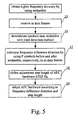
- correcting carrier deviation is implemented by two big steps, which are shown in Fig. 4 and 5 , respectively.
- Fig.4 the first big step, a frequency difference is estimated by software and a decision and feedback mechanism for hardware adjustment is introduced.
- frequency difference is recovered from an initial larger value to a smaller range; for example, when using a crystal oscillator with accuracy 3ppm and working frequency range about 2G, the initial value can be considered as about 6 kHz.
- the second big step by mainly using joint detection technology to suppress multipath and multiple access interference, the smaller frequency difference (for example, about 1kHz) will be corrected to a range required by baseband demodulation in order to obtain a more accurate frequency difference information for guiding hardware adjustment.
- Fig.4 is an uninterrupted procedure starting from recovering carrier frequency difference until higher frequency accuracy obtained by using midamble.
- the frequency difference is estimated by software, the automatic frequency control (AFC) is made for hardware by a decision and feedback mechanism.
- the procedure corrects frequency difference from an initial larger value to a smaller range.
- Estimating frequency difference by software is also a software compensation process. If only using the software compensation without adjustment for hardware, each time the estimation must be accurate. In addition, under wireless channel the software estimation method is not estimation without tolerance. Therefore, only with software compensation, the effect is not good enough. On the other hand, although under wireless channel the software estimation is not very accurate, but the estimated frequency difference direction is reliable, especially in an average of multiple frames. Therefore, the software estimation can be used to guide the AFC hardware adjustment, to satisfy the requirement of the first big step. The specific steps are as follow.
- Step 12 estimate frequency difference of each data frame by software with formula (2): Ae - jk ⁇ ⁇ 1 L ⁇ L I i + jQ i * ⁇ I ⁇ i + K + jQ ⁇ i + K * Wherein ⁇ represents an estimated frequency difference, I and Q are orthogonal demodulation signal, L is a statistic length.
- fe(n) is an estimated frequency difference, i.e. ⁇ for the n th data frame received; adjustment coefficient coef k ranges between 0 ⁇ 1, the selection principle is that greater k takes smaller coef k .
- a received data frame can be divided into k1, k2, ..., kn sections; when there are k1 ⁇ k2 ⁇ ... ⁇ kn , take coef k1 . > coef k2 > ... > coef kn .
- Q is a preset number of adjustment frames
- the feedback in this case is interadjusting between software and hardware, i.e. first calculate frequency difference with software, then adjust hardware guided by the calculated frequency difference; after hardware has been adjusted, software estimates frequency difference again; repeat the procedure until a preset number of times.
- Fig.5 shows a procedure that deploys midamble to obtain higher frequency accuracy. Based on joint detection, a smaller frequency deviation is corrected into a range, which can be borne by the baseband demodulation.
- using joint detection technology means inserting a training sequence (midamble) to each frame for estimating real channel response.
- user equipment can suppress multipath and multiple access interference with joint detection technology, demodulates data symbols near the training sequence midamble, and guides adjustment of AFC by using frequency deviation information involved in these symbols. Specific steps are as following:
- Steps 15 to 19 can be repeated. Along with a corrected frequency difference decreases gradually, more data symbols near the training sequence midamble can be taken to obtain more frequency difference information, and the adjustment step length of AFC hardware can be decreased gradually.
- the method of the invention is a cell initial search method based on having training sequence system and can be used in a CDMA mobile communication system.
- a CDMA communication system using joint detection technology can use the invention, which is a method for correcting carrier deviation based on joint detection, to estimate carrier deviation. In a space wireless channel environment, the method can have a well effect.
- the invention a downlink synchronization and carrier deviation correction method, is designed based on a TD-SCDMA system, which is proposed by CWTS (China Wireless Telecommunication Standardization) and is one of the RTT (Radio Transmission Technology) of International IMT-2000, but it can be fully used on other digital cellular mobile communication systems after an adequate update.
- CWTS China Wireless Telecommunication Standardization
- RTT Radio Transmission Technology
Abstract
Description
- The present invention relates generally to mobile communication technology, and more particularly to a cell initial search method of user equipment (UE) in a CDMA digital cellular mobile communication system with training sequence (pilot).
- In a digital cellular mobile communication system, after an UE is turned on, a cell initial search is made first. Purposes of the cell initial search are to select a suitable working frequency and to obtain downlink synchronization between the UE and a base station at this working frequency. Only in this way, the UE can correctly receive message sent by the base station.
- Additionally, in a real digital cellular mobile communication system, the main clock in UE and a base station is completely independent. Even if both are working at same working frequency, there must be a carrier deviation (or called frequency difference, frequency deviation) between them. During demodulation, if UE cannot implement relative accurate carrier deviation recovery (or said calibration, correction), then there will be remaining carrier component in the baseband signal, this will affect processing of the baseband signal, further cause code error and make the UE cannot correctly receive information sent by a base station.
- Therefore, for a digital cellular mobile communication system, UE must perform the following works during cell initial search: working frequency locking, obtaining downlink synchronization with the base station at the locked working frequency, correcting carrier frequency deviation.
- Naturally, during a real cell initial search, because the independent main clocks of a base station and UE drift along with time, so carrier frequency deviation also must be traced at the same time.
- In a real CDMA cellular mobile communication system, in general the downlink synchronization is performed by a pilot channel. The convention implementation of a downlink synchronization are: first, locking at a working frequency, then solving the correlation between the whole data frame received and a preset pilot sequence (training sequence), continuously sliding the working frequency for solving correlation until the correlation peak is greater than a preset threshold, then the downlink synchronization is performed at this working frequency. The working frequency where the correlation peak is located is the UE receiving position.
- In any CDMA cellular mobile communication system, it is needed to perform correlation operation for synchronization. Nevertheless, the conventional correlation operation has the following limitation. As the correlation operation is slid at each chip or even fractional chip level of the whole data frame, so the operation volume is huge and a long calculation time is needed. Besides, as the correlation operation is taken for whole data frame, it increases probability of error decision, especially, in the Time Division Duplex CDMA (TDD-CMDA) system. In a TDD-CDMA system, suppose near UE A there is another UE B is in conversation. As the distance between UE A and B is short, so the UE A receives a more powerful signal power sent by UE B than a signal power sent by the base station. This leads a mistaken decision about the correlation peak position that is not the real receiving position of the UE, and produces mistaken downlink synchronization information.
- In general, carrier frequency deviation is corrected at a digital demodulator (for general situation, a certain degree of carrier deviation will not affect downlink synchronization, but will affect the demodulated information). An analogy phase-locked circuit, which is mature in technology, is used in convention. Disadvantages of this solution are: it is difficult to take account of performance and capture bandwidth at the same time, and it is sensitive to carrier jitter and it is complex for hardware circuit.
- In the China Patent
CN 97115151.2 named "a method and device for carrier recovery and compensation in a frequency spread communication system", a digital correction method for carrier frequency deviation has been proposed. Nevertheless, the method makes an optimal estimation under a channel model without noise and multipath interference, and is not suitable for a cellular mobile communication system. - "Universal Mobile Telecommunications System (UMTS); Physical Layer Procedures (TDD) (3G TS 25.224 version 3.1.1 Release 1999); ETSI TS 125 224" discloses initial cell search, which is carried out in three steps: Step 1: slot synchronization, during which the UE uses the primary synchronization code cp to acquire slot synchronization to the strongest cell; Step 2: frame synchronization and code-group identification, during which the UE uses the modulated Secondary Synchronization codes to find frame synchronization and identify one out of 32 code groups; Step 3: scrambling code identification, during which the UE determines the exact basic midamble code and the accompanying scrambling code used by the found cell.
-
EP 0852430 A2 discloses an initial synchronization method for a DS-CDMA inter base station asynchronous cellular system, which comprises: receiving a control signal in the control channel of a base station, correlating the control signal with the specific short code to produce a correlation signal, determining a long code synchronization timing of the control signal based on the correlation signal, detecting correlation between the control signal and segments of the synthesized spread code sequences, and identifying which of the different long codes synthesizes said one of the synthesized spread code sequence. - Purpose of the invention is to provide a cell initial search method for a CDMA digital mobile communication system. The method improves the conventional cell initial search method, i.e. proposes a solution for downlink synchronization and carrier deviation correction during cell initial search. With this solution UE can rapidly and accurately perform downlink synchronization with base station and has a better effect for carrier deviation correction.
- An implementation of the invention can be as follows:
- A cell initial search method for a digital mobile communication system with CDMA is used for a user equipment correctly receiving information sent by a base station. The method includes that the user equipment selects a working frequency;
- the said: "obtaining downlink synchronization with the base station at the working frequency point" includes that:
- by using a power characteristic window value method based on training sequence, a range of downlink training sequence timeslot is decided first; and
- in the range by calculating correlation of received data and training sequence, an accurate receiving position of the user equipment is obtained.;
- the said: "the power characteristic window value method based on training sequence" comprises:
- in a base station frame structure, increasing transmitting power of synchronization symbols in the downlink pilot sequence timeslot (DwPTS), and there is no transmitting power on protected symbols located before and after the synchronization symbols in the DwPTS; and
- when receiving, user equipment first searches power characteristic window values of the DwPTS, after a position range of the synchronization symbols has been discovered, the correlation operation is only made near the position;
- the said: "searching power characteristic window values of the DwPTS to discover a position range of the synchronization symbols", includes that:
- UE locks a working frequency first, then receives a data frame; calculate each synchronization symbol power in the DwPTS; calculate power characteristic window values at each synchronization symbol position; calculate average power characteristic window value for the whole data frame; search minimum one of power characteristic window values at all synchronization symbols position of the whole data frame received; decide whether the ratio of average power characteristic window value and minimum power characteristic window value is greater than a threshold value, if it is, then position of the minimum power characteristic window value is the beginning position of the DwPTS; solve correlation near the beginning position to obtain an accurate receiving beginning point and end the downlink synchronization;
- the said: "calculate power characteristic window value at each synchronization symbol position" is that on the whole data frame received with symbol level sliding, calculate each position power characteristic window value R(i) at each position with the following formula:

wherein i represents a real receiving position, P(k) represents power value of each symbol, N and M are characteristic window parameters. - The said: "calculate each synchronization symbol power" is that first suppose the receiving moment is a synchronization symbol beginning point, then add powers of all chips belonging to the symbol to obtain the power of each synchronization symbol.
- The said: "calculate power characteristic window value at each synchronization symbol position" is that based on each chip power with chip level sliding, calculate power characteristic window value at each position.
- The method further includes:
- tracing carrier deviation between the user equipment and the base station by the user equipment, and correcting the carrier deviation in a digital demodulator of the user equipment;
- wherein correcting the carrier deviation in a digital demodulator of the user equipment comprises:
- estimating the carrier deviation by software, and adjusting hardware by using a decision and feedback method; and
- by using a carrier deviation correction method based on joint detection, suppressing multipath and multiple access interference and correcting the carrier deviation to a range required by baseband demodulation.
- The said: "estimating the carrier deviation by software, and adjusting hardware by using a decision and feedback method" includes: estimating carrier deviation of each data frame by software, calculating adjustment value for hardware, adjusting automatic frequency control hardware in the digital demodulator with the calculated adjustment value.
- The following formula is used to estimate frequency difference of each data frame by software:

- The following formula is used to calculate hardware adjustment value, i.e. for calculating adjustment value of a carrier frequency difference:

wherein fe(n) is the estimated frequency difference for the nth data frame received, the range of adjustment coefficient coefk is between 0 ~ 1, and when k is greater, select a smaller coefk. - The said: "by using a carrier deviation correction method based on joint detection, suppressing multipath and multiple access interference and correcting the carrier deviation to a range required by baseband demodulation" includes: a training sequence midamble of data burst is inserted into each frame; the user equipment suppresses multipath and multiple access interference with joint detection technology, and symbols near the training sequence midamble is demodulated; with carrier frequency difference information included in these symbols, automatic frequency control hardware is adjusted.
- The said: "suppress multipath and multiple access interference with joint detection technology, and symbols near the training sequence midamble is demodulated" further includes: demodulate data with the joint detection technology and obtain P characters before and after the training sequence midamble, and recorded as X(1) ... X(P) and Y(1) ... Y(P), respectively; calculate Xi(n)=X(n)/Xj(n), Yi(n) = Y(n)/Yj(n), wherein Xj(n) = Yj(n) = ±π/4, ±3π/4; obtain carrier frequency difference direction by formula:

- The said: "estimating the carrier deviation by software, and adjusting hardware by using a decision and feedback method" includes:
- a) setting frame number n = 0, receiving a data frame;
- b) estimating carrier frequency deviation of the data frame by software;
- c) calculating a adjustment value of carrier frequency deviation, i.e. calculating hardware adjustment value;
- d) adjusting automatic frequency control hardware according to the calculated hardware adjustment value, doing n = n+1, deciding whether n being greater than a preset number of adjustment frames Q, if not being so, receiving next data frame and going to step b, otherwise ending.
- The said: "by using a carrier deviation correction method based on joint detection, suppressing multipath and multiple access interference and correcting the carrier deviation to a range required by baseband demodulation" includes:
- e) receiving m data frames;
- f) demodulating the m data frames received with joint detection technology, i.e. demodulating data symbols near a training sequence midamble and getting P symbols before and after the training sequence midamble, respectively;
- g) calculating carrier frequency deviation direction on the P symbols before and after the training sequence midamble of m data frames, respectively;
- h) setting an adjustment step length for automatic frequency control hardware, according to the calculated carrier frequency deviation direction;
- i) adjusting automatic frequency control hardware with the adjustment step length, according to the frequency carrier deviation direction obtained.
- The steps e to i are repeated.
- The invention is a cell initial search method for a CDMA mobile communication system, and is a downlink synchronization method for a CDMA mobile communication system. The method implements locking a working frequency point during a cell initial search, obtaining downlink synchronization with the base station and recovering carrier frequency difference between the base station and user equipment. The method of locking a working frequency point and obtaining downlink synchronization with the base station is: first, deciding a rough range of the training sequence by using a power characteristic window value method based on training sequence, then solving correlation of a data frame received and the training sequence to obtain the accurate receiving position and to complete a downlink synchronization with the base station. The method of recovering carrier frequency difference between the base station and user equipment is a carrier frequency difference correction method based on joint detection technology. Implementing several steps of the two methods above (or any one of them) will implement a cell initial search of the invention and user equipment completes downlink synchronization rapidly and accurately.
- The method of the invention is a cell initial search method mainly pointed to mobile communication system with training sequence.
-
-
Fig.1 is a diagram of cell initial search. -
Fig.2 is a frame structure diagram required when using the power characteristic window value method. - Firure3 is a flowchart implementing the power characteristic window value method.
-
Fig.4 is a flowchart for correcting an initial larger frequency difference range to a smaller frequency difference range in the correction of carrier frequency difference. -
Fig.5 is a flowchart for correcting frequency difference to a range required by baseband demodulation in the correction of carrier frequency difference. - The present invention now will be described more fully hereinafter with reference to the accompanying drawings, in which preferred embodiments of the invention are shown. This invention may, however, be embodied in many different forms and should not be construed as limited to the embodiments set forth herein; rather, these embodiments are provided so that this disclosure will be thorough and complete, and will fully convey the scope of the invention to those skilled in the art. Like numbers refer to like elements throughout.
-
Fig.1 shows basic steps of a cell initial search procedure from starting to ending in a cellular mobile communication system, by taking a Time Division - Synchronized Code Division Multiple Access (TD-SCDMA) system as an example. Step1 searches a rough position range of DwPTS by using the power characteristic window value method of the invention, and defines the working frequency point. Step2 searches accurate receiving position by using conventional solving correlation method in the position range defined bystep 1, and obtains accurate receiving position. Step3 start to recover carrier frequency difference based on the joint detection method of carrier frequency difference correction used in the invention. In step4, information in the broadcast channel (BCCH) can be monitored. -
Fig.2 shows a frame structure required when using the power characteristic window value method for implementing downlink synchronization. In the invention, two training sequences are defined in a frame structure of TD-SCDMA system: anindependent DwPTS 5 and a midamble in burst data TD0 ..... TDn, TU0 ..... Tun. The two training sequences have different function during a cell initial search. TheDwPTS 5 occupies an independent timeslot including N GP (guard) symbols, M SYNC (synchronization) symbols and again N GP symbols. Before and after the midamble, there are P data symbols, respectively, and the two data symbols and the midamble together occupy a timeslot. The SYNC symbol is a code selected from a set of orthogonal codes. The code can be obtained by solving correlation, but the operation must be made over whole data frame and the set of orthogonal codes, so the operation volume is very large. - In the downlink synchronization method of the invention, let base station raise transmitting power of SYNC symbols but there is no transmitting power at GP symbols. In this way when receiving, user equipment can first search the power characteristic window value of the DwPTS, and discovers a rough position range of the SYNC symbols, then solves correlation only near the position range. Therefore, the downlink synchronization time will be greatly shrunk and probability of decision error will be decreased.
-
Fig.3 shows procedure for searching rough position range of DwPTS. Taking TD-SCDMA system as an example, the procedure starts searching with the characteristic window method and ends with discovering the rough position range of DwPTS or without finding the rough position range of DwPTS. In the TD-SCDMA system, set number of guard symbols N = 2, number of SYNC symbols M = 4 and each data frame time length is 5ms. - In step6, first user equipment is locked at a working frequency point, which should be a possible frequency point of a mobile communication system, and then the user equipment receives a complete data frame (e.g. 5ms + Δ ms). In step7, calculate each symbol power P, i.e. first suppose that the receiving moment is the starting point of a symbol, then add power of all chips belong to the symbol to obtain the symbol power. Although, in real the receiving moment cannot be just the starting point of a symbol, but purpose of using power characteristic window value method is to obtain a rough position range of SYNC symbol. Therefore, there is no so much affect to the result.
- In the following formula (1), Rt is the power characteristic window value for each position, i represents the real receiving position, P(k) represents each symbol power, M and N are parameters of the characteristic window shape.

- In step8, calculate power characteristic window value (ratio) on each symbol position. For a receiveing data frame sliding in symbol level and on each position taking the TD-SCDMA frame structure N = 2, M = 4, calculate power characteristic window value with the formula ((Pi + P i+1) + (P i+6 + P i+7))/(P i+2 + P i+3 + P i+4 + P i+5).
- Practically, it need not take each symbol power, but take each chip power. Sliding in chip level can obtain more accurate result, but it charges a larger operation volume.
- In step 9, calculate average power characteristic window value (ratio) on a frame: Raver, with the formula:

Wherein R(i) is a power characteristic window value on each receiving position, Q represents number of receiving position for a frame. - In
step 10, search the minimum one of power characteristic window value in a receiving data frame: Rmin, Rmin = min(R(i)); and calculate Raver / Rmin, i.e. average power characteristic window value/ minimum power characteristic window value, to see whether Raver / Rmin is much more greater than a threshold value. If Raver / Rmin is not greater than the threshold, then the DwPTS has not been found. If Raver / Rmin is greater than the threshold, then the position of the minimum value of power characteristic window is the DwPTS starting position. Then, solve correlation near the obtained starting position of the DwPTS to obtain an accurate receiving starting point and perform downlink synchronization. - In the invention, correcting carrier deviation is implemented by two big steps, which are shown in
Fig. 4 and5 , respectively. InFig.4 , the first big step, a frequency difference is estimated by software and a decision and feedback mechanism for hardware adjustment is introduced. In the first big step, frequency difference is recovered from an initial larger value to a smaller range; for example, when using a crystal oscillator with accuracy 3ppm and working frequency range about 2G, the initial value can be considered as about 6 kHz. InFig.5 , the second big step, by mainly using joint detection technology to suppress multipath and multiple access interference, the smaller frequency difference (for example, about 1kHz) will be corrected to a range required by baseband demodulation in order to obtain a more accurate frequency difference information for guiding hardware adjustment. -
Fig.4 is an uninterrupted procedure starting from recovering carrier frequency difference until higher frequency accuracy obtained by using midamble. During this procedure, the frequency difference is estimated by software, the automatic frequency control (AFC) is made for hardware by a decision and feedback mechanism. The procedure corrects frequency difference from an initial larger value to a smaller range. - Estimating frequency difference by software is also a software compensation process. If only using the software compensation without adjustment for hardware, each time the estimation must be accurate. In addition, under wireless channel the software estimation method is not estimation without tolerance. Therefore, only with software compensation, the effect is not good enough. On the other hand, although under wireless channel the software estimation is not very accurate, but the estimated frequency difference direction is reliable, especially in an average of multiple frames. Therefore, the software estimation can be used to guide the AFC hardware adjustment, to satisfy the requirement of the first big step. The specific steps are as follow.
- Before
step 11, set frame number n = 0, and step 11 receives a data frame. -
Step 12, estimate frequency difference of each data frame by software with formula (2):
Wherein α represents an estimated frequency difference, I and Q are orthogonal demodulation signal, L is a statistic length. - Step13, with formula (3) calculate adjustment value of carrier frequency difference, i.e. hardware adjustment value:

Wherein fe(n) is an estimated frequency difference, i.e. α for the nth data frame received; adjustment coefficient coefk ranges between 0 ~ 1, the selection principle is that greater k takes smaller coefk. For example, a received data frame can be divided into k1, k2, ..., kn sections; when there are k1<k2< ... <kn, take coefk1. > coefk2 >...> coefkn. - Stepl4, adjust hardware AFC control according to the calculated hardware adjustment value, do n = n+1, decide whether n > Q? When n is not greater than Q (Q is a preset number of adjustment frames), repeat steps 11 to 14 until n > Q, then the first big step is ended and go to using midamble for higher frequency accuracy.
- In practice, it also can be feedback without each data frame, but with multiple frames. The feedback in this case is interadjusting between software and hardware, i.e. first calculate frequency difference with software, then adjust hardware guided by the calculated frequency difference; after hardware has been adjusted, software estimates frequency difference again; repeat the procedure until a preset number of times.
-
Fig.5 shows a procedure that deploys midamble to obtain higher frequency accuracy. Based on joint detection, a smaller frequency deviation is corrected into a range, which can be borne by the baseband demodulation. In a TD-SCDMA system, using joint detection technology means inserting a training sequence (midamble) to each frame for estimating real channel response. In this way, user equipment can suppress multipath and multiple access interference with joint detection technology, demodulates data symbols near the training sequence midamble, and guides adjustment of AFC by using frequency deviation information involved in these symbols. Specific steps are as following: - Step15, receive m data frames.
- Stepl6, demodulate the m data frames with joint detection technology, i.e. demodulate data symbols near the training sequence midamble and obtain P symbols before and after the training sequence midamble, respectively, which can be named as X(1) ... X(P) and Y(1) ... Y(P), respectively.
-
Step 17, calculate, respectively, the frequency deviation direction by using formula (4) on the P symbols before and after the training sequence midamble of the m data frames:
Wherein Xj(n) = Yj(n) = ±π/4, ±3π/4;
Then use formula (5) to obtain a carrier frequency difference:
-
Step 18, set adjustment step length (STEP Hz) of AFC hardware, according to the calculated frequency difference direction. - Step19, according to the frequency difference direction obtained in step17, adjust AFC hardware with the step length STEP.
-
Steps 15 to 19 can be repeated. Along with a corrected frequency difference decreases gradually, more data symbols near the training sequence midamble can be taken to obtain more frequency difference information, and the adjustment step length of AFC hardware can be decreased gradually. - The method of the invention is a cell initial search method based on having training sequence system and can be used in a CDMA mobile communication system. A CDMA communication system using joint detection technology can use the invention, which is a method for correcting carrier deviation based on joint detection, to estimate carrier deviation. In a space wireless channel environment, the method can have a well effect.
- Although, the invention, a downlink synchronization and carrier deviation correction method, is designed based on a TD-SCDMA system, which is proposed by CWTS (China Wireless Telecommunication Standardization) and is one of the RTT (Radio Transmission Technology) of International IMT-2000, but it can be fully used on other digital cellular mobile communication systems after an adequate update.
Claims (12)
- A cell initial search method for a CDMA digital mobile communication system, for a user equipment receiving information sent by a base station, comprising:selecting a working frequency point by the user equipment and obtaining downlink synchronization with the base station at the working frequency point; it is characterized that:whereinobtaining downlink synchronization with the base station at the working frequency point comprises:deciding (1) a range of downlink training sequence timeslot by using a power characteristic window value method based on training sequence; andobtaining (2) accurate receiving position for the user equipment by calculating correlation of received data and training sequence in the range;wherein the power characteristic window value method based on training sequence comprises:increasing transmitting power of synchronization symbols in a downlink pilot sequence timeslot, DwPTS, of a base station data frame, and there is no transmitting power on protected symbols located before and after the synchronization symbols in the DwPTS; andsearching power characteristic window values of the DwPTS first by user equipment, during receiving, and after having been discovered a position range of the synchronization symbols, making correlation calculation only near the position;wherein searching power characteristic window values of the DwPTS to discover a position range of the synchronization symbols comprises:locking (6) a working frequency point by the user equipment first, and receiving a data frame;calculating (7) each synchronization symbol power in the DwPTS;calculating (8) power characteristic window values at each synchronization symbol position;calculating (9) average power characteristic window value over the complete data frame;searching (10) minimum one of power characteristic window values at all synchronization symbols position of the receiving data frame;deciding (10) whether the ratio of average power characteristic window value and minimum power characteristic window value being greater than a threshold value, if it being so, then the position of the minimum power characteristic window value being the beginning position of the DwPTS; andsolving correlation near the beginning position to obtain an accurate receiving beginning point and ending downlink synchronization;wherein calculating power characteristic window values at each synchronization symbol position comprises:sliding with symbol level on the receiving data frame, and calculating each position power characteristic window value R(i) at each position with a following formula:

where i represents a real receiving position, P(k) represents a power value of each synchronization symbol, N and M are characteristic window parameters. - The method according to Claim1, wherein calculating each synchronization symbol power comprises:supposing the receiving moment being a synchronization symbol beginning point first, adding powers of all chips belonging to the synchronization symbol, and getting the power of the synchronization symbol.
- The method according to Claim1, wherein calculating power characteristic window values at each synchronization symbol position comprises:sliding with chip level based on each chip power, and calculating the power characteristic window value at each position.
- The method according to Claim 1, further comprising:tracing carrier deviation between the user equipment and the base station by the user equipment, and correcting the carrier deviation in a digital demodulator of the user equipment;wherein correcting the carrier deviation in a digital demodulator of the user equipment comprises:estimating the carrier deviation by software, and adjusting hardware by using a decision and feedback method; andby using a carrier deviation correction method based on joint detection, suppressing (3) multipath and multiple access interference and correcting the carrier deviation to a range required by baseband demodulation.
- The method according to Claim4, wherein estimating the carrier deviation by software, and adjusting hardware by using a decision and feedback method comprises:estimating the carrier deviation of each data frame by software;calculating a adjustment value for hardware; andadjusting automatic frequency control, AFC, hardware in the digital demodulator with the calculated adjustment value.
- The method according to Claim5, wherein using a following formula to estimate the carrier deviation of each data frame:

wherein α represents the estimated frequency deviation, I and Q are orthogonal demodulation signals, and L is a statistic length. - The method according to Claim5, wherein using a following formula to calculate an adjustment value for hardware:

wherein fe(n) is the estimated carrier frequency deviation for the nth receiving data frame, the range of adjustment coefficient coefk is between 0 ~ 1, and when k is greater, select a smaller coefk. - The method according to Claim 4, wherein by using a carrier deviation correction method based on joint detection, suppressing multipath and multiple access interference and correcting the carrier deviation to a range required by baseband demodulation comprises:inserting a training sequence midamble of data burst into each data frame for estimating real channel response;suppressing multipath and multiple access interference with joint detection technology by the user equipment, and demodulating symbols near the training sequence midamble;adjusting automatic frequency control hardware with the carrier deviation information included in these symbols.
- The method according to Claim8, wherein suppressing multipath and multiple access interference with joint detection technology and demodulating symbols near the training sequence midamble comprises:demodulating receiving data with joint detection technology, and getting P characters before and after the training sequence midamble, and recorded as X(1) ... X(P) and Y(1) ... Y(P), respectively;calculating Xi(n) = X(n)/Xj(n), Yi(n) = Y(n) / Yj(n), respectively, wherein Xj(n) = Yj(n) = ±π/4 or ±3π/4;getting carrier deviation direction by the formula:
 setting an adjustment step length of automatic frequency control hardware based on the calculated carrier frequency deviation direction; andadjusting automatic frequency control hardware with the adjustment step length according to the carrier frequency deviation direction.
 - The method according to Claim4, wherein estimating the carrier deviation by software, and adjusting hardware by using a decision and feedback method comprises:a) setting (11) frame number n = 0, receiving a data frame;b) estimating (12) carrier frequency deviation of the data frame by software;c) calculating (13) a adjustment value of carrier frequency deviation, i.e. calculating hardware adjustment value;d) adjusting (14) automatic frequency control hardware according to the calculated hardware adjustment value, doing n = n+1, deciding whether n being greater than a preset number of adjustment frames Q, if not being so, receiving next data frame and going to step b, otherwise ending.
- The method according to Claim4 or 10, wherein by using a carrier deviation correction method based on joint detection, suppressing multipath and multiple access interference and correcting the carrier deviation to a range required by baseband demodulation comprises:e) receiving (15) m data frames;f) demodulating (16) the m data frames received with joint detection technology, i.e. demodulating data symbols near a training sequence midamble and getting P symbols before and after the training sequence midamble, respectively;g) calculating (17) carrier frequency deviation direction on the P symbols before and after the training sequence midamble of m data frames, respectively;h) setting (18) an adjustment step length for automatic frequency control hardware, according to the calculated carrier frequency deviation direction;i) adjusting (19) automatic frequency control hardware with the adjustment step length, according to the frequency carrier deviation direction obtained.
- The method according to Claim11, further comprises repeating steps e to i.
Applications Claiming Priority (3)
| Application Number | Priority Date | Filing Date | Title |
|---|---|---|---|
| CN00103548 | 2000-03-27 | ||
| CN00103548A CN1131653C (en) | 2000-03-27 | 2000-03-27 | Small-region initial search method for CDMA digital mobile communication system |
| PCT/CN2001/000018 WO2001074103A1 (en) | 2000-03-27 | 2001-01-12 | Method of cell initial search in cdma digital mobile telecommunication system |
Publications (3)
| Publication Number | Publication Date |
|---|---|
| EP1330136A1 EP1330136A1 (en) | 2003-07-23 |
| EP1330136A4 EP1330136A4 (en) | 2009-11-04 |
| EP1330136B1 true EP1330136B1 (en) | 2012-03-07 |
Family
ID=4577070
Family Applications (1)
| Application Number | Title | Priority Date | Filing Date |
|---|---|---|---|
| EP01900378A Expired - Lifetime EP1330136B1 (en) | 2000-03-27 | 2001-01-12 | Method of cell initial search in cdma digital mobile telecommunication system |
Country Status (13)
| Country | Link |
|---|---|
| US (1) | US6778588B2 (en) |
| EP (1) | EP1330136B1 (en) |
| JP (1) | JP4530603B2 (en) |
| KR (1) | KR100564826B1 (en) |
| CN (1) | CN1131653C (en) |
| AT (1) | ATE548807T1 (en) |
| AU (2) | AU2500401A (en) |
| BR (1) | BRPI0109610B1 (en) |
| CA (1) | CA2403929C (en) |
| MX (1) | MXPA02009561A (en) |
| RU (1) | RU2274954C2 (en) |
| TW (1) | TW508967B (en) |
| WO (1) | WO2001074103A1 (en) |
Families Citing this family (44)
| Publication number | Priority date | Publication date | Assignee | Title |
|---|---|---|---|---|
| JP3851525B2 (en) * | 2001-08-09 | 2006-11-29 | 株式会社エヌ・ティ・ティ・ドコモ | Mobile station apparatus, mobile communication system, and carrier detection method |
| KR100524730B1 (en) * | 2002-11-02 | 2005-10-31 | 엘지전자 주식회사 | Early syncrounization search method for mobile communication system |
| CN1224280C (en) * | 2002-12-27 | 2005-10-19 | 大唐移动通信设备有限公司 | Time-varying channel correction method for time-division slot mobile communication system |
| CN1512794A (en) * | 2002-12-30 | 2004-07-14 | �ʼҷ����ֵ��ӹɷ�����˾ | Small cell searching method and device for mobile terminal in TDD-CDMA system |
| WO2004066532A1 (en) * | 2003-01-23 | 2004-08-05 | Linkair Communications,Inc. | Implement method and apparatus for downlink synchronization subsystem |
| US7633927B2 (en) * | 2003-01-31 | 2009-12-15 | Nokia Corporation | System and method for extending neighboring cell search window |
| CN1259785C (en) * | 2003-08-04 | 2006-06-14 | 大唐移动通信设备有限公司 | Method for obtaining carrier frequency departure of time division synchronous CDMA (TD-SCDMA) user terminal and equipment |
| CN1263322C (en) * | 2003-08-06 | 2006-07-05 | 大唐移动通信设备有限公司 | Gain control method for community initial search in TD-SCDMA mobile communication system |
| KR100565313B1 (en) * | 2003-11-26 | 2006-03-30 | 엘지전자 주식회사 | Method of time domain and code domain power measurement for combined tdma and cdma operated communication system |
| CN1303839C (en) * | 2003-12-19 | 2007-03-07 | 北京天碁科技有限公司 | Method and device for reducing sum of calculation for searching in zones and increasing accuracy of calculation |
| CN100337508C (en) * | 2004-01-12 | 2007-09-12 | 大唐移动通信设备有限公司 | Method for searching down synchronous signal position in mobile communication system |
| CN1298114C (en) * | 2004-05-14 | 2007-01-31 | 中兴通讯股份有限公司 | A method for determining preact of time |
| CN100403657C (en) * | 2004-05-25 | 2008-07-16 | 大唐移动通信设备有限公司 | TD-SCDMA system frequency offset compensating method and apparatus based on exercising sequence |
| CN100356704C (en) * | 2004-06-02 | 2007-12-19 | 大唐移动通信设备有限公司 | Method for compensating frequency offset in wireless mobile communication system |
| CN100369386C (en) * | 2004-06-29 | 2008-02-13 | 大唐移动通信设备有限公司 | A combined detection method and apparatus with incorporated frequency deviation compensation |
| CN100362892C (en) * | 2004-07-01 | 2008-01-16 | 凯明信息科技股份有限公司 | Method and apparatus of initial cell search in time division synchronous CDMA system |
| ATE445274T1 (en) | 2004-08-05 | 2009-10-15 | Lg Electronics Inc | INTERRUPTION OF THE USE OF THE FREQUENCY LAYER CONVERGENCE PROCESS |
| US7684378B2 (en) * | 2004-11-08 | 2010-03-23 | Interdigital Technology Corporation | Method and apparatus for estimating channelization codes in a wireless transmit/receive unit |
| CN1780175B (en) * | 2004-11-19 | 2010-09-29 | 上海宣普实业有限公司 | The first and second steps series iterative method for cell searching in time-divided duplexing system |
| CN1780174B (en) * | 2004-11-19 | 2011-05-25 | 上海宣普实业有限公司 | The first and second steps series iterative method for area searching in time divided duplexing system |
| US7917140B2 (en) | 2004-12-06 | 2011-03-29 | Telefonaktiebolaget L M Ericsson (Publ) | Initial cell search in mobile communications systems |
| WO2006067657A1 (en) * | 2004-12-24 | 2006-06-29 | Koninklijke Philips Electronics N.V. | Method and apparatus for cell search in wireless communication system |
| CN1797990B (en) * | 2004-12-27 | 2010-12-08 | 上海宣普实业有限公司 | Method for scanning frequency points in TDS-CDMA system |
| WO2006121302A1 (en) | 2005-05-13 | 2006-11-16 | Samsung Electronics Co., Ltd. | Method and apparatus for indexing physical channels in an ofdma system |
| CN100409588C (en) * | 2005-06-03 | 2008-08-06 | 上海原动力通信科技有限公司 | United detection method for multiple cells in time division code division multiple access |
| CN1905406B (en) * | 2005-07-28 | 2011-04-20 | 上海原动力通信科技有限公司 | Synchronous method for wideband time division duplex cellular system |
| CN1988415B (en) * | 2005-12-21 | 2010-04-14 | 大唐移动通信设备有限公司 | Method for judging downward pilot frequency signal transmission mode in CDMA communication system |
| CN1996791B (en) * | 2006-01-06 | 2015-09-09 | 上海原动力通信科技有限公司 | A kind of downlink synchronization method of broadband time and division duplex cellular system |
| CN101009513B (en) * | 2006-01-26 | 2013-02-13 | 上海原动力通信科技有限公司 | Cell synchronization method and initial cell searching method for broadband time-division dual-duplex cellular system |
| KR101208541B1 (en) | 2006-11-01 | 2012-12-05 | 엘지전자 주식회사 | Method For Detecting The Position Of Synchronization Signal, And Method For Searching Cell Using The Same |
| CN101072438B (en) * | 2007-06-15 | 2010-09-29 | 中兴通讯股份有限公司 | Initial cell searching method for TD-SCDMA system mobile terminal |
| JP2009089203A (en) * | 2007-10-02 | 2009-04-23 | Panasonic Corp | Radio apparatus, and radio communication system |
| CN101222280B (en) * | 2007-11-30 | 2012-02-29 | 深圳国人通信有限公司 | Single time slot power detecting method and system |
| JP2009141832A (en) * | 2007-12-10 | 2009-06-25 | Mitsubishi Electric Corp | Communication system, reception terminal equipment, and radio base station |
| CN101958746B (en) * | 2010-04-02 | 2014-03-12 | 展讯通信(上海)有限公司 | Coarse synchronization method of wireless terminal |
| CN102821442B (en) * | 2011-06-10 | 2014-10-22 | 联芯科技有限公司 | Scan method and device for frequency points |
| CN103298101B (en) * | 2013-06-19 | 2016-02-17 | 中国人民解放军空军工程大学 | A kind of code subcarrier synchronization realizing method of wide region |
| CN104253680B (en) | 2013-06-27 | 2018-07-31 | 华为技术有限公司 | The sending method and device of synchronizing signal in a kind of FBMC systems |
| KR102421473B1 (en) * | 2015-10-01 | 2022-07-18 | 삼성전자주식회사 | Communication device performing carrier search in TD-SCDMA system and control method thereof |
| CN105933052B (en) * | 2016-05-20 | 2019-09-06 | 中国电子科技集团公司第十研究所 | Time domain cross polarization interference offsets method |
| CN105897304B (en) * | 2016-05-31 | 2018-02-06 | 西安空间无线电技术研究所 | A kind of fast synchronization method of frequency-hopping communication system |
| WO2018163440A1 (en) | 2017-03-10 | 2018-09-13 | Nec Corporation | Position estimation apparatus |
| EP3769483A1 (en) * | 2018-03-20 | 2021-01-27 | Telefonaktiebolaget LM Ericsson (publ) | A wireless device, a network node and methods therein for enabling and determining reference signal configurations in a wireless communications network |
| CN114584438B (en) * | 2022-01-05 | 2023-08-15 | 华信咨询设计研究院有限公司 | 5G CFO estimation method based on reference carrier frequency offset |
Family Cites Families (13)
| Publication number | Priority date | Publication date | Assignee | Title |
|---|---|---|---|---|
| US5805983A (en) * | 1996-07-18 | 1998-09-08 | Ericsson Inc. | System and method for equalizing the delay time for transmission paths in a distributed antenna network |
| US6128470A (en) * | 1996-07-18 | 2000-10-03 | Ericsson Inc. | System and method for reducing cumulative noise in a distributed antenna network |
| JP2937897B2 (en) * | 1996-09-30 | 1999-08-23 | 株式会社ワイ・アール・ピー移動通信基盤技術研究所 | Channel assignment method and communication network using the method |
| JP3376224B2 (en) * | 1996-10-23 | 2003-02-10 | 株式会社エヌ・ティ・ティ・ドコモ | Initial synchronization method and receiver in asynchronous cellular system between DS-CDMA base stations |
| JP3373746B2 (en) | 1997-01-07 | 2003-02-04 | 株式会社鷹山 | Initial synchronization method and receiver in asynchronous cellular system between DS-CDMA base stations |
| KR100393239B1 (en) * | 1997-06-17 | 2003-07-31 | 지멘스 악티엔게젤샤프트 | Method, mobile station and base station for time synchronization for a mobile station in a radio communications system |
| CN1061205C (en) * | 1997-07-24 | 2001-01-24 | 北京信威通信技术有限公司 | Method for device of carrier exalting and compensating in frequency spreading communication system |
| JPH11112472A (en) * | 1997-08-04 | 1999-04-23 | Toshiba Corp | Spread spectrum communication equipment |
| JP3897427B2 (en) * | 1997-12-01 | 2007-03-22 | 松下電器産業株式会社 | Base station apparatus, mobile station apparatus, mobile communication system, radio transmission method, and radio reception method |
| JP3793632B2 (en) * | 1997-12-18 | 2006-07-05 | 松下電器産業株式会社 | Cell search method and mobile station apparatus |
| US6490454B1 (en) * | 1998-08-07 | 2002-12-03 | Telefonaktiebolaget Lm Ericsson (Publ) | Downlink observed time difference measurements |
| KR20040008204A (en) * | 2001-05-31 | 2004-01-28 | 노오텔 네트웍스 리미티드 | Apparatus and method for measuring sub-carrier frequencies and sub-carrier frequency offsets |
| WO2003047117A2 (en) * | 2001-11-29 | 2003-06-05 | Interdigital Technology Corporation | System and method using primary and secondary synchronization codes during cell search |
-
2000
- 2000-03-27 CN CN00103548A patent/CN1131653C/en not_active Expired - Lifetime
-
2001
- 2001-01-12 AU AU2500401A patent/AU2500401A/en active Pending
- 2001-01-12 KR KR1020027012743A patent/KR100564826B1/en active IP Right Grant
- 2001-01-12 CA CA 2403929 patent/CA2403929C/en not_active Expired - Lifetime
- 2001-01-12 BR BRPI0109610-9A patent/BRPI0109610B1/en not_active IP Right Cessation
- 2001-01-12 AT AT01900378T patent/ATE548807T1/en active
- 2001-01-12 AU AU2001225004A patent/AU2001225004B2/en not_active Expired
- 2001-01-12 WO PCT/CN2001/000018 patent/WO2001074103A1/en active IP Right Grant
- 2001-01-12 RU RU2002128747A patent/RU2274954C2/en active
- 2001-01-12 JP JP2001571693A patent/JP4530603B2/en not_active Expired - Lifetime
- 2001-01-12 MX MXPA02009561A patent/MXPA02009561A/en active IP Right Grant
- 2001-01-12 EP EP01900378A patent/EP1330136B1/en not_active Expired - Lifetime
- 2001-08-24 TW TW90121115A patent/TW508967B/en not_active IP Right Cessation
-
2002
- 2002-09-25 US US10/255,334 patent/US6778588B2/en not_active Expired - Lifetime
Also Published As
| Publication number | Publication date |
|---|---|
| EP1330136A1 (en) | 2003-07-23 |
| TW508967B (en) | 2002-11-01 |
| JP2003529302A (en) | 2003-09-30 |
| CN1131653C (en) | 2003-12-17 |
| WO2001074103A1 (en) | 2001-10-04 |
| RU2274954C2 (en) | 2006-04-20 |
| KR20020092401A (en) | 2002-12-11 |
| WO2001074103A8 (en) | 2003-05-15 |
| AU2500401A (en) | 2001-10-08 |
| BRPI0109610B1 (en) | 2015-08-18 |
| CA2403929C (en) | 2008-09-23 |
| JP4530603B2 (en) | 2010-08-25 |
| MXPA02009561A (en) | 2004-07-30 |
| AU2001225004B2 (en) | 2005-03-17 |
| CA2403929A1 (en) | 2002-09-24 |
| KR100564826B1 (en) | 2006-03-30 |
| RU2002128747A (en) | 2004-03-10 |
| US6778588B2 (en) | 2004-08-17 |
| BR0109610A (en) | 2003-06-17 |
| CN1315808A (en) | 2001-10-03 |
| EP1330136A4 (en) | 2009-11-04 |
| US20030031238A1 (en) | 2003-02-13 |
| ATE548807T1 (en) | 2012-03-15 |
Similar Documents
| Publication | Publication Date | Title |
|---|---|---|
| EP1330136B1 (en) | Method of cell initial search in cdma digital mobile telecommunication system | |
| US8005129B2 (en) | Acquisition circuit for low chip rate option for mobile telecommunication system | |
| EP1653645B1 (en) | A method and device of the estimating carrier frequency offset of subscriber terminal | |
| US8738054B2 (en) | Efficient frame tracking in mobile receivers | |
| EP1668786B1 (en) | Initial synchronization for receivers | |
| CN1607787B9 (en) | The automatic frequency correcting method of time-diviional radiocommunication system | |
| CN101599794B (en) | TD-SCDMA communication system frequency synchronization method and device | |
| CN1607788B (en) | Automatic frequency correcting method for receiver of time-division wireless communication system | |
| CN1607787B (en) | Automatic frequency correcting method for time-division wireless communication system | |
| KR101137344B1 (en) | Method and apparatus for estimating frame synchronization | |
| CN1777160B (en) | Coarse frequency correcting method |
Legal Events
| Date | Code | Title | Description |
|---|---|---|---|
| PUAI | Public reference made under article 153(3) epc to a published international application that has entered the european phase |
Free format text: ORIGINAL CODE: 0009012 |
|
| 17P | Request for examination filed |
Effective date: 20020917 |
|
| AK | Designated contracting states |
Designated state(s): AT BE CH CY DE DK ES FI FR GB GR IE IT LI LU MC NL PT SE TR |
|
| A4 | Supplementary search report drawn up and despatched |
Effective date: 20091007 |
|
| 17Q | First examination report despatched |
Effective date: 20100421 |
|
| REG | Reference to a national code |
Ref country code: DE Ref legal event code: R079 Ref document number: 60146215 Country of ref document: DE Free format text: PREVIOUS MAIN CLASS: H04Q0007360000 Ipc: H04B0001707000 |
|
| RIC1 | Information provided on ipc code assigned before grant |
Ipc: H04B 1/707 20110101AFI20110530BHEP |
|
| GRAP | Despatch of communication of intention to grant a patent |
Free format text: ORIGINAL CODE: EPIDOSNIGR1 |
|
| GRAS | Grant fee paid |
Free format text: ORIGINAL CODE: EPIDOSNIGR3 |
|
| GRAA | (expected) grant |
Free format text: ORIGINAL CODE: 0009210 |
|
| AK | Designated contracting states |
Kind code of ref document: B1 Designated state(s): AT BE CH CY DE DK ES FI FR GB GR IE IT LI LU MC NL PT SE TR |
|
| REG | Reference to a national code |
Ref country code: GB Ref legal event code: FG4D |
|
| REG | Reference to a national code |
Ref country code: AT Ref legal event code: REF Ref document number: 548807 Country of ref document: AT Kind code of ref document: T Effective date: 20120315 Ref country code: CH Ref legal event code: EP |
|
| REG | Reference to a national code |
Ref country code: IE Ref legal event code: FG4D |
|
| REG | Reference to a national code |
Ref country code: DE Ref legal event code: R096 Ref document number: 60146215 Country of ref document: DE Effective date: 20120510 |
|
| REG | Reference to a national code |
Ref country code: NL Ref legal event code: VDEP Effective date: 20120307 |
|
| PG25 | Lapsed in a contracting state [announced via postgrant information from national office to epo] |
Ref country code: NL Free format text: LAPSE BECAUSE OF FAILURE TO SUBMIT A TRANSLATION OF THE DESCRIPTION OR TO PAY THE FEE WITHIN THE PRESCRIBED TIME-LIMIT Effective date: 20120307 |
|
| PG25 | Lapsed in a contracting state [announced via postgrant information from national office to epo] |
Ref country code: FI Free format text: LAPSE BECAUSE OF FAILURE TO SUBMIT A TRANSLATION OF THE DESCRIPTION OR TO PAY THE FEE WITHIN THE PRESCRIBED TIME-LIMIT Effective date: 20120307 Ref country code: GR Free format text: LAPSE BECAUSE OF FAILURE TO SUBMIT A TRANSLATION OF THE DESCRIPTION OR TO PAY THE FEE WITHIN THE PRESCRIBED TIME-LIMIT Effective date: 20120608 |
|
| REG | Reference to a national code |
Ref country code: AT Ref legal event code: MK05 Ref document number: 548807 Country of ref document: AT Kind code of ref document: T Effective date: 20120307 |
|
| PG25 | Lapsed in a contracting state [announced via postgrant information from national office to epo] |
Ref country code: CY Free format text: LAPSE BECAUSE OF FAILURE TO SUBMIT A TRANSLATION OF THE DESCRIPTION OR TO PAY THE FEE WITHIN THE PRESCRIBED TIME-LIMIT Effective date: 20120307 |
|
| PG25 | Lapsed in a contracting state [announced via postgrant information from national office to epo] |
Ref country code: SE Free format text: LAPSE BECAUSE OF FAILURE TO SUBMIT A TRANSLATION OF THE DESCRIPTION OR TO PAY THE FEE WITHIN THE PRESCRIBED TIME-LIMIT Effective date: 20120307 Ref country code: BE Free format text: LAPSE BECAUSE OF FAILURE TO SUBMIT A TRANSLATION OF THE DESCRIPTION OR TO PAY THE FEE WITHIN THE PRESCRIBED TIME-LIMIT Effective date: 20120307 |
|
| PG25 | Lapsed in a contracting state [announced via postgrant information from national office to epo] |
Ref country code: PT Free format text: LAPSE BECAUSE OF FAILURE TO SUBMIT A TRANSLATION OF THE DESCRIPTION OR TO PAY THE FEE WITHIN THE PRESCRIBED TIME-LIMIT Effective date: 20120709 |
|
| PLBE | No opposition filed within time limit |
Free format text: ORIGINAL CODE: 0009261 |
|
| STAA | Information on the status of an ep patent application or granted ep patent |
Free format text: STATUS: NO OPPOSITION FILED WITHIN TIME LIMIT |
|
| PG25 | Lapsed in a contracting state [announced via postgrant information from national office to epo] |
Ref country code: AT Free format text: LAPSE BECAUSE OF FAILURE TO SUBMIT A TRANSLATION OF THE DESCRIPTION OR TO PAY THE FEE WITHIN THE PRESCRIBED TIME-LIMIT Effective date: 20120307 Ref country code: DK Free format text: LAPSE BECAUSE OF FAILURE TO SUBMIT A TRANSLATION OF THE DESCRIPTION OR TO PAY THE FEE WITHIN THE PRESCRIBED TIME-LIMIT Effective date: 20120307 |
|
| 26N | No opposition filed |
Effective date: 20121210 |
|
| PG25 | Lapsed in a contracting state [announced via postgrant information from national office to epo] |
Ref country code: IT Free format text: LAPSE BECAUSE OF FAILURE TO SUBMIT A TRANSLATION OF THE DESCRIPTION OR TO PAY THE FEE WITHIN THE PRESCRIBED TIME-LIMIT Effective date: 20120307 |
|
| REG | Reference to a national code |
Ref country code: DE Ref legal event code: R097 Ref document number: 60146215 Country of ref document: DE Effective date: 20121210 |
|
| PG25 | Lapsed in a contracting state [announced via postgrant information from national office to epo] |
Ref country code: ES Free format text: LAPSE BECAUSE OF FAILURE TO SUBMIT A TRANSLATION OF THE DESCRIPTION OR TO PAY THE FEE WITHIN THE PRESCRIBED TIME-LIMIT Effective date: 20120618 |
|
| PG25 | Lapsed in a contracting state [announced via postgrant information from national office to epo] |
Ref country code: MC Free format text: LAPSE BECAUSE OF NON-PAYMENT OF DUE FEES Effective date: 20130131 |
|
| REG | Reference to a national code |
Ref country code: CH Ref legal event code: PL |
|
| REG | Reference to a national code |
Ref country code: IE Ref legal event code: MM4A |
|
| PG25 | Lapsed in a contracting state [announced via postgrant information from national office to epo] |
Ref country code: LI Free format text: LAPSE BECAUSE OF NON-PAYMENT OF DUE FEES Effective date: 20130131 Ref country code: CH Free format text: LAPSE BECAUSE OF NON-PAYMENT OF DUE FEES Effective date: 20130131 |
|
| PG25 | Lapsed in a contracting state [announced via postgrant information from national office to epo] |
Ref country code: IE Free format text: LAPSE BECAUSE OF NON-PAYMENT OF DUE FEES Effective date: 20130112 |
|
| PG25 | Lapsed in a contracting state [announced via postgrant information from national office to epo] |
Ref country code: TR Free format text: LAPSE BECAUSE OF FAILURE TO SUBMIT A TRANSLATION OF THE DESCRIPTION OR TO PAY THE FEE WITHIN THE PRESCRIBED TIME-LIMIT Effective date: 20120307 |
|
| PG25 | Lapsed in a contracting state [announced via postgrant information from national office to epo] |
Ref country code: LU Free format text: LAPSE BECAUSE OF NON-PAYMENT OF DUE FEES Effective date: 20130112 |
|
| REG | Reference to a national code |
Ref country code: FR Ref legal event code: PLFP Year of fee payment: 16 |
|
| REG | Reference to a national code |
Ref country code: FR Ref legal event code: PLFP Year of fee payment: 17 |
|
| REG | Reference to a national code |
Ref country code: FR Ref legal event code: PLFP Year of fee payment: 18 |
|
| PGFP | Annual fee paid to national office [announced via postgrant information from national office to epo] |
Ref country code: GB Payment date: 20200131 Year of fee payment: 20 Ref country code: DE Payment date: 20200113 Year of fee payment: 20 |
|
| PGFP | Annual fee paid to national office [announced via postgrant information from national office to epo] |
Ref country code: FR Payment date: 20200130 Year of fee payment: 20 |
|
| REG | Reference to a national code |
Ref country code: DE Ref legal event code: R071 Ref document number: 60146215 Country of ref document: DE |
|
| REG | Reference to a national code |
Ref country code: GB Ref legal event code: PE20 Expiry date: 20210111 |
|
| PG25 | Lapsed in a contracting state [announced via postgrant information from national office to epo] |
Ref country code: GB Free format text: LAPSE BECAUSE OF EXPIRATION OF PROTECTION Effective date: 20210111 |