EP1330091A1 - Procédé de sélection d'une position d'une fenêtre FFT dans un récepteur COFDM - Google Patents
Procédé de sélection d'une position d'une fenêtre FFT dans un récepteur COFDM Download PDFInfo
- Publication number
- EP1330091A1 EP1330091A1 EP03354004A EP03354004A EP1330091A1 EP 1330091 A1 EP1330091 A1 EP 1330091A1 EP 03354004 A EP03354004 A EP 03354004A EP 03354004 A EP03354004 A EP 03354004A EP 1330091 A1 EP1330091 A1 EP 1330091A1
- Authority
- EP
- European Patent Office
- Prior art keywords
- module
- carriers
- symbol
- signaling
- tps
- Prior art date
- Legal status (The legal status is an assumption and is not a legal conclusion. Google has not performed a legal analysis and makes no representation as to the accuracy of the status listed.)
- Granted
Links
- 238000000034 method Methods 0.000 title claims abstract description 5
- 239000000969 carrier Substances 0.000 claims abstract description 101
- 230000011664 signaling Effects 0.000 claims abstract description 41
- 238000012360 testing method Methods 0.000 claims description 29
- 238000012545 processing Methods 0.000 claims description 25
- 238000004364 calculation method Methods 0.000 claims description 23
- 238000012937 correction Methods 0.000 claims description 16
- 238000000605 extraction Methods 0.000 claims description 3
- 230000009466 transformation Effects 0.000 claims description 3
- 238000004458 analytical method Methods 0.000 abstract description 27
- 230000005540 biological transmission Effects 0.000 description 17
- 230000006870 function Effects 0.000 description 15
- 230000004044 response Effects 0.000 description 13
- 238000001228 spectrum Methods 0.000 description 6
- 230000004048 modification Effects 0.000 description 4
- 238000012986 modification Methods 0.000 description 4
- 239000013598 vector Substances 0.000 description 4
- 238000002592 echocardiography Methods 0.000 description 3
- 238000005070 sampling Methods 0.000 description 3
- 239000000284 extract Substances 0.000 description 2
- 230000002441 reversible effect Effects 0.000 description 2
- 101150071746 Pbsn gene Proteins 0.000 description 1
- 230000008859 change Effects 0.000 description 1
- 238000010276 construction Methods 0.000 description 1
- 230000003111 delayed effect Effects 0.000 description 1
- 238000011161 development Methods 0.000 description 1
- 238000001914 filtration Methods 0.000 description 1
- 238000005259 measurement Methods 0.000 description 1
- 230000010363 phase shift Effects 0.000 description 1
- 230000008569 process Effects 0.000 description 1
- 238000003908 quality control method Methods 0.000 description 1
- 238000004088 simulation Methods 0.000 description 1
- 230000002123 temporal effect Effects 0.000 description 1
- 230000007704 transition Effects 0.000 description 1
- 230000017105 transposition Effects 0.000 description 1
- 238000012795 verification Methods 0.000 description 1
Images


Classifications
-
- H—ELECTRICITY
- H04—ELECTRIC COMMUNICATION TECHNIQUE
- H04L—TRANSMISSION OF DIGITAL INFORMATION, e.g. TELEGRAPHIC COMMUNICATION
- H04L25/00—Baseband systems
- H04L25/02—Details ; arrangements for supplying electrical power along data transmission lines
- H04L25/0202—Channel estimation
- H04L25/0224—Channel estimation using sounding signals
- H04L25/0228—Channel estimation using sounding signals with direct estimation from sounding signals
- H04L25/023—Channel estimation using sounding signals with direct estimation from sounding signals with extension to other symbols
- H04L25/0232—Channel estimation using sounding signals with direct estimation from sounding signals with extension to other symbols by interpolation between sounding signals
-
- H—ELECTRICITY
- H04—ELECTRIC COMMUNICATION TECHNIQUE
- H04L—TRANSMISSION OF DIGITAL INFORMATION, e.g. TELEGRAPHIC COMMUNICATION
- H04L25/00—Baseband systems
- H04L25/02—Details ; arrangements for supplying electrical power along data transmission lines
- H04L25/0202—Channel estimation
- H04L25/022—Channel estimation of frequency response
-
- H—ELECTRICITY
- H04—ELECTRIC COMMUNICATION TECHNIQUE
- H04L—TRANSMISSION OF DIGITAL INFORMATION, e.g. TELEGRAPHIC COMMUNICATION
- H04L27/00—Modulated-carrier systems
- H04L27/26—Systems using multi-frequency codes
- H04L27/2601—Multicarrier modulation systems
- H04L27/2647—Arrangements specific to the receiver only
- H04L27/2655—Synchronisation arrangements
- H04L27/2662—Symbol synchronisation
-
- H—ELECTRICITY
- H04—ELECTRIC COMMUNICATION TECHNIQUE
- H04L—TRANSMISSION OF DIGITAL INFORMATION, e.g. TELEGRAPHIC COMMUNICATION
- H04L27/00—Modulated-carrier systems
- H04L27/26—Systems using multi-frequency codes
- H04L27/2601—Multicarrier modulation systems
- H04L27/2647—Arrangements specific to the receiver only
- H04L27/2655—Synchronisation arrangements
- H04L27/2662—Symbol synchronisation
- H04L27/2665—Fine synchronisation, e.g. by positioning the FFT window
-
- H—ELECTRICITY
- H04—ELECTRIC COMMUNICATION TECHNIQUE
- H04L—TRANSMISSION OF DIGITAL INFORMATION, e.g. TELEGRAPHIC COMMUNICATION
- H04L5/00—Arrangements affording multiple use of the transmission path
- H04L5/003—Arrangements for allocating sub-channels of the transmission path
- H04L5/0048—Allocation of pilot signals, i.e. of signals known to the receiver
Definitions
- the present invention relates to a type demodulator COFDM ("Coded Orthogonal Frequency Division Multiplex" or multiplexing by coded orthogonal frequency division) or the like.
- COFDM Coded Orthogonal Frequency Division Multiplex
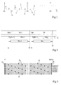
- Figure 1 is intended to illustrate the principle of a COFDM modulation.
- Data packets to be sent are put under the form of N complex coefficients associated with N frequencies (or carriers).
- the number N of frequencies is equal to example at 1705 for the so-called "2K” mode and at 6817 for the so-called mode "8K", in herzian transmission of digital television.
- Each complex coefficient corresponds to a vector which is illustrated in figure 1 as starting from a frequency axis at a point indicating the frequency associated with the coefficient.
- IFFT inverse fast Fourier
- Tu is the duration of emission of a symbol and is called useful life.
- the useful life is around 224 ⁇ s in 2K mode and 896 ⁇ s in 8K mode, for a bandwidth of 8MHz.
- a receiver subjects the symbol to reverse processing, i.e. mainly a transform fast Fourier (FFT) to reconstruct the coefficients starting complexes.
- FFT transform fast Fourier
- some vectors P1, P2, P3 ... regularly distributed have a value known constant. These vectors, or carriers are called pilots. They serve to reflect the distortions suffered by the transmitted signal and by information they give on the channel response they allow to correct the unknown vectors located between the drivers.
- FIG. 2 illustrates a transmission of several successive symbols Sn-1, Sn ... As shown, each of these symbols is preceded by a guard interval Tgn-1, Tgn which is a copy of part of the end of the symbol corresponding. Guard intervals are often defined by a fraction of the useful life Tu. Classic values of the guard interval are Tu / 32, Tu / 16, Tu / 8 or Tu / 4.
- Guard intervals are used to avoid inter-symbol modulation distortions caused by an echo of the transmission.
- Figure 2 also shows an echo SEn-1, TgEn-1 ... of the transmitted signal. This echo is delayed by compared to the main signal of a duration shorter than that of a guard interval Tg.
- Each symbol S is normally analyzed by the receiver FFT circuit in a window W of the same length as the symbol. If there was no guard interval, a analysis window W coinciding with a signal symbol main would straddle two symbols of the echo signal. This would cause an error which is difficult to correct in the calculation of the FFT Fourier transform.
- the guard interval Tg offers a margin of adjustment of the analysis window W so that it only coincides with portions belonging to the same symbol, both in the signal main than in the echo.
- the symbol Sn-1 must be analyzed in a window Wn-1 which can extend from time ta, corresponding to the start of the echo guard interval TgEn-1, at time tb corresponding to the end of the symbol Sn-1.
- the symbol Sn must be analyzed in a Wn window may extend from time tc, corresponding to the start of the echo guard interval TgEn, at time td corresponding to the end of the symbol Sn.
- the positioning of the analysis windows W is carried out conventionally using the drivers contained in the symbols.
- Figure 3 shows schematically the place of pilots in symbols. Symbols are grouped in frames of 68 symbols, conventionally in radio transmission from digital television (standard ETSI EN 300 744, V1.4.1).
- each line represents a symbol and each box represents the position of a carrier.
- the carriers are defined as going from a position 0 to a Kmax position, Kmax being equal to 1704 in 2K mode and 6816 in 8K mode. Indeed, only part of the possible frequencies is used, in particular due to the risk of losses along the canal.
- the pilots are of two types.
- pilots Pr so-called “scattered pilots”, which are arranged every 12 carriers, and offset by three positions between two successive symbols. So, all four symbols, we find the same arrangement of distributed pilots Pr.
- the complex received signal temporal, after being put in baseband, is provided to a fast Fourier transform module providing the symbol in the frequency domain.
- the pilots are taken from this symbol.
- the sampled pilots allow the estimation frequency of the channel which, after having undergone a transform of Reverse Fourrier, provides the impulse response of the channel.
- the channel impulse response is used to position finely the window.
- An object of the present invention is to provide a COFDM demodulator or the like with an optimal positioning of the FFT analysis window.
- Another object of the present invention is to provide a COFDM demodulator or the like with re-positioning the FFT analysis window.
- the present invention provides a COFDM type demodulator including a circuit fast Fourier transform of analysis of a signal received in a window corresponding to a symbol, each symbol carrying several carriers modulated in phase and / or in amplitude, some of which are signal carriers, and a circuit for positioning said window.
- the circuit of positioning of said window is suitable for using the non demodulated signal carriers.
- the positioning circuit of said window comprises a signal carrier processing module and a module window adjustment device coupled with the signal carriers.
- the signaling carrier processing module is suitable for developing a quality criterion from carriers signaling.
- the demodulator comprises one or more first modules of correction coupled to the fast Fourier transform circuit and ordered from said quality criterion.
- the positioning circuit of said window comprises at least a circuit comprising one or more second modules of correction of the same function as the first module (s) correction and coupled to the carrier processing module of signaling, itself coupled to a calculation module coupled to window adjustment module and suitable for controlling the second correction modules.
- the signaling carrier processing module includes a third calculation module coupled to the first and second summers capable of providing the said quality criterion, the said quality criterion being a representative number of the sum the smaller among the sums provided by the first and second summers.
- the processing module includes a first clipping module coupled to the first summator and the third calculation module and a second clipping module coupled to the second adder and to the third calculation module.
- the present invention also provides a method of COFDM type demodulation including a step of transformation by fast Fourier transform analyzing a signal received in a window corresponding to a symbol, each symbol conveying several carriers modulated in phase and / or in amplitude, some of which are carriers of signaling, and a step of positioning said window.
- the step of positioning said window comprises a step development of a quality criterion from the carriers of non demodulated signaling.
- the present invention uses the carriers of signaling, called “TPS carriers", present in the signal issued.
- TPS carriers the carriers of signaling
- the TPS Transmission Parameters Signaling
- the TPS carriers are specific carriers distributed in the frequency spectrum available.
- the TPS carriers contain information of encoding or decoding. For example, they indicate the type of carrier modulation, such as "QPSK”, 64 QAM, 16 QAM, etc. mode, 2K or 8K, the value of the guard interval, the number of the frame, etc.
- TPS carriers always occupy the same place in symbols. In each symbol, the TPS carriers are all identical before coding.
- TPS carriers are coded with conventional type coding DBPSK, in order to have a transmission energy substantially constant.
- TPS carriers in 2K mode, and 68 in 8K mode.
- the TPS carriers occupy, in the frequency spectrum, locations located between those of continuous pilots and of distributed pilots.
- the use, according to the present invention, of TPS carriers for adjusting the positioning of the window will make it possible to refine this positioning and make it optimal.
- TPS carriers Due to their coding, TPS carriers cannot take only two values, and match either number complex (1,0), that is to say to the real number "1", or to the number complex (-1.0), ie the real number "-1". Like the TPS carriers of the same symbol are all identical before coding, if the first TPS carrier of a symbol corresponds to (1,0), the values of the other TPS carriers of the symbol are determined. The same is true when the first TPS carrier of the symbol corresponds to (-1.0). Due to transmission, GST carriers received correspond to a complex number (x, y) or x + iy in a plane I, Q, I representing the elements in phase and Q the quadrature elements of the carrier, like this is illustrated in figure 4.
- a decoding of the carriers TPS and a noise measurement on them allow to define an EPQ quality criterion for the window and, more generally, demodulation.
- the EPQ quality criterion is used especially to offset the window, if necessary, so that optimize its positioning. Note that the calculation of the criterion quality EPQ does not use the demodulated values of TPS carriers.
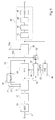
- Figure 5 shows an example of a demodulator according to the present invention.
- the signal received includes pilots continuous, distributed pilots, TPS carriers and data carriers.
- an input E of the demodulator receives a IF signal of intermediate frequency allowing a sampling, for example 36 MHz.
- IF signal corresponds to signal received after various changes or transpositions of frequency.
- Input E is coupled to an analog-digital converter 10 (ADC) which digitizes the IF input signal.
- ADC analog-digital converter 10
- the analog-to-digital converter 10 attacks a module 12 of frequency change.
- Module 12 provides a signal substantially in baseband, the signal spectrum at the output of the module 12 being centered on a frequency substantially equal to zero.
- the module 12 is coupled to a module 14 allowing a apart from fine tuning of the center frequency of the spectrum signal and, secondly, to provide time samples to appropriate times for further processing.
- the signal spectrum is centered on a frequency equal to 0 and the number and time position of samples are suitable for transformation by transform of Fourier which takes place in the next module.
- Module 14 is controlled by links 15 and 15 'connecting the module 14 to a module 16 for processing continuous and distributed pilots.
- module 14 attacks a module 20 of fast Fourier transform (FFT) which provides the frequencies corresponding to a symbol.
- FFT fast Fourier transform
- the module 20 is controlled by a module 22 which provides, via a link 24, a signal for setting the transform analysis window of Fourier.
- module 20 The output of module 20 is coupled to module 16 which extracts and processes continuous pilots and distributed.
- Module 16 provides on links 15 and 15 'the signals to correct the center frequency of the spectrum and the signal sampling frequency.
- the output of module 20 attacks a module 30 in which the signal is corrected using an estimate of the frequency response of the channel. Estimation of the response frequency of the channel is performed in module 16 using pilots. This estimate is provided by module 16 on a link 55, one branch 55a of which is coupled to the module 30.
- the signal includes the TPS carriers, not demodulated, and the carriers carrying the data, not demodulated also (by demodulation, we mean extracting information conveyed by these carriers).
- Module 26 provides the answer impulse from channel to module 22, to dynamically adjust the positioning of the FFT analysis window.
- Circuit 40 has a conventional structure and can include, as shown in Figure 4, a module 42 symbol deinterlacing, a module 44 called “demapping", a module 46 of bit deinterlacing, and a error correction module 48 (FEC).
- Module 48 output constitutes the output S of circuit 40 and of the demodulator and provides data corresponding to the transmitted data.
- module 30 also attacks a module 50 of processing of TPS carriers.
- Module 50 including an example of realization will be described in relation to FIG. 6, provides an EPQ quality criterion on a link 52.
- the quality attacks, directly or indirectly, module 22 intended for adjust the setting of the analysis window.
- the module 22 receives the output signal from module 14 via a link 54, to roughly adjust the analysis window.
- An example of known module 22 is for example present in the integrated circuit STV 0360 manufactured by the applicant.
- This integrated circuit includes a so-called "protection" register long echo protection ".
- the content of the far echo protection register used to fine tune the setting of the FFT analysis window and is determined from the criterion EPQ quality supplied by module 50, after a possible data processing.
- a microcontroller internal or external to the demodulator, can be coupled to the module 22 to receive the EPQ quality criterion and modify the contents of the far echo protection register in order to minimize the quality criterion.
- the quality criterion has a low value, the window is well positioned and no adjustment is not made.
- the quality criterion has a high value, adequate repositioning of the window is realized.
- the microcontroller mentioned above can also carry out tests by modifying periodically or not the contents of the far echo protection register.
- the microcontroller then notes the different values of the criterion of quality obtained and controls the positioning of the window analysis using the command that provided the value quality criteria.
- the correction module 30 generally comprises filters of which centering is carried out in conjunction with the positioning of the FFT analysis window.
- the EPQ criterion, used to positioning of the FFT analysis window, can also be used for the possible centering of these filters.
- the response of the channel can only be known with certainty that a point out of three samples.
- the indication provided by carriers TPS is an indication which relates to points of the sampling sequence.
- the redundancy and coding of the TPS carriers make the carriers TPS particularly robust to noise. It results from remarks above that adjusting the FFT analysis window using of carriers TPS is particularly effective.
- the Applicant has carried out numerous tests of simulation using echoes before the signal main ("pre-echo”, “precursive echo” in English) or echoes intervening after the main signal ("post-echo”, “postcursive echo "in English).
- FIG. 6 illustrates an advantageous example of realization of module 50 for processing TPS carriers.
- the module 50 receives the signal at the output of module 30 as input.
- signal includes TPS carriers and carriers carrying the data.
- the input signal is supplied to a module 58 which extracts the TPS carriers.
- the TPS numbers are supplied to an adder 60 and a subtractor 62.
- the adder 60 and the subtractor 62 receive in in addition each one a sequence of numbers TPS '.
- TPS numbers are determined as follows.
- a suitable module 65 any, for example a memory element or a register, sequentially supplies a number of "1" equal to number of carriers used in the transmission mode used (1705 in 2K mode and 6817 in 8K mode).
- module 65 attacks a module 67.
- the module 67 modifies the digital sequence supplied to it according to a PRBS sequence defined by the ETSI standard mentioned above.
- output from module 67 there is a reference sequence corresponding to the sequence of TPS pilots and carriers issued.
- the output of module 67 attacks a module 69.
- the module 69 has the function of extracting from the sequence transmitted by the module 67, TPS 'numbers corresponding to the locations of TPS carriers.
- the TPS 'numbers represent a theoretical sequence of corresponding TPS numbers to an error-free transmission and in the event that the first symbol carrier TPS corresponds to the value 1.
- modules 65, 67 and 69 can be replaced by one or more other appropriate modules.
- a single module can directly provide the desired sequence of TPS 'numbers. Note, however, that the Figure 6 structure allows a certain symmetrization of the circuit, module 69 corresponding to module 58, and that this structure is easily configurable depending on the mode of operation.
- the adder 60 adds the complex number TPS to the TPS number 'for each of the TPS carriers.
- the exit of the adder 60 attacks a module 70.
- the module 70 calculates the complex absolute value of the sum TPS + TPS ', defined by the sum of the absolute value of the real part of the number GST + GST 'and the absolute value of the imaginary part of the number TPS + TPS '.
- module 70 can calculate the quadratic distance between the numbers TPS and TPS ', or the calculation of another distance between the numbers GST AND GST '.
- the module 70 is coupled to a module 72 (SUM).
- the module 72 realizes, for each symbol, the sum of all values provided by module 70.
- the output from module 72 attacks a clipping module 74 intended to limit the output of the module 72 if exceeded.
- Module 74 provides a number at. For example, if the output of module 50 is intended for 8-bit numbers, the number a, in binary representation, is limited to eight "1" if this value is exceeded.
- module 80 realizes the complex absolute value of the difference in numbers TPS and TPS '.
- module 80 performs the same calculation as module 70.
- the output from module 80 attacks module 82 which performs the sum absolute values provided by module 80 for all TPS carriers present in a symbol.
- the output of module 82 attacks a clipping module 84 with the same function as the module 74.
- Module 84 provides a number b for each symbol.
- the number b is related to the distance of the TPS carriers received at their theoretical value, if the first TPS carrier of the symbol corresponds to a "1".
- the number a is related to the distance from the TPS carriers received at their theoretical value, if the first TPS carrier of the symbol corresponds to a "-1", the sequences starting with a "1” and a "-1" being inverse one the other. Indeed, the sum GST + GST 'can be interpreted like the difference TPS - (- TPS '), which corresponds to the distance of the TPS number received at point (-1.0).
- the number a can be calculated from of a sequence of TPS numbers "corresponding to the sequence, in a symbol, numbers corresponding to the TPS carriers when the first TPS carrier of the symbol corresponds to a "-1". it would have led to a duplication of elements 65, 67 and 69, operating from a value "-1".
- the fact, in figure 6, to use an adder 60 and a subtractor 62 from of the same sequence avoids the duplication mentioned above.
- the numbers a and b attack a module 90.
- the module 90 analyzes the numbers a and b and provides an equal min (a, b) whichever of the numbers a or b has the greater value low.
- the min number (a, b) is provided at the output of module 50 on link 52 towards module 22.
- the number min (a, b) corresponds to the distance between the GST carriers received and GST carriers transmitted the most likely. This number is an estimate of noise or errors affecting the TPS carriers received. It is this number, min (a, b), which, according to the present invention, is used as a criterion for EPQ quality to modify the positioning of the window FFT analysis. If the quality criterion has a low value, this means that the TPS carriers received are close to carriers transmitted and the window is well positioned. Otherwise, by example above a certain threshold, the value of the criterion of quality controls the positioning of the window so as to make it optimal.
- FIG. 7 illustrates a demodulator according to the present invention in which the fine positioning adjustment of the Fourier transform analysis window is realized from automatically at the hardware level by modules present in the receiver. These modules make it possible to carry out adjustment tests without intervening in the main processing data and choose the optimal positioning of the FFT analysis window.
- a signal to analyze like the one provided by module 14 of figure 5, drives a fast FFT 20 'Fourier transform module.
- Module 100 includes a module 102 intended to extract the continuous pilots and the distributed pilots contained in the signal from module 20 '.
- the output from module 102 attacks a prediction module 104, i.e. estimation, channel frequency determined from pilots.
- a prediction module 104 i.e. estimation, channel frequency determined from pilots.
- At the output of module 104 is a signal corresponding to the frequency estimate of the channel determined at from the pilots.
- the signal from module 104 attacks a module interpolator 106.
- the interpolator module 106 performs two functions, an interpolation function using a filter interpolator and a filter centering function interpolation.
- the centering of the interpolation filter is controlled by a centering control signal CS circulating on a 24 "line coming from a module 22 'which will be described by after.
- the filtering of the signal supplied by the module 104 allows to obtain, at the output of the interpolator module 106, a estimated channel information for all carriers and repositioned in time.
- the signal from module 20 ' also attacks a centering module 110 which reposition this signal over time.
- the centering carried out in the module 110 is controlled by the centering control signal CS carried on the 24 "line and is carried out in the same way as the centering carried out in the module 106.
- CS centering control signal
- the correction module 112 provides, on an OUT output, a signal comprising the carriers TPS and the data carriers corrected for their deformation due to the frequency response of the channel.
- module 112 can perform the complex division between the signals from module 110 and module 106 so that get time repositioned data from the same so that the carriers, the channel then being entirely valued.
- the signal present on the OUT output can attack a processing circuit, like circuit 40 in FIG. 5, for the provision of data conveyed by the carriers of data.
- a module 50 'with the same function as module 50 in FIG. 5 can be connected to the OUT output.
- the 50 'module aims to calculate the quality criterion, referenced here EPQ ', and supply outside the demodulator, in particular for the purpose of control or verification.
- module 102 and 104 are carried out by a part of the circuit 16 of FIG. 5 and that the function of module 30 in FIG. 5 is produced by modules 106, 110 and 112 in Figure 7.
- the signals provided respectively by the module 104 and module 20 ' also attack a test loop 200 intended to calculate various values of the quality criterion EPQ.
- the test loop 200 comprises an interpolator module 206, a centering module 210, corrector module 212, determination of quality criteria 50 "and a calculation module 250.
- the signal provided by the module 104 attacks the module interpolator 206 via a line 211.
- the module 206 has the same function as module 106 and can be the same constitution or not (for example, module 206 can be simplified construction compared to module 106).
- the module 206 performs signal interpolation and time centering present on line 211. Centering is performed by the module 206 using a centering control signal EVi present on a line 260.
- the module 206 provides a signal corresponding to the estimated channel response for all signal carriers.
- the module 210 receives the signal supplied by the module 20 'via a line 213.
- the module 210 is same function as module 110 and can be the same constitution or not.
- Module 210 performs a correction identical to that performed in module 206.
- the module 210 is controlled by the centering control signal EVi present on line 260.
- the output of module 206 and the output of module 210 attack the corrector module 212.
- the module 212 has the same function, if applicable the same constitution, as the module 112.
- At the output of module 212 there is a signal comprising the TPS signal carriers corrected for their deformations due to the frequency response of the channel and repositioned in time using the control signal centering provided by line 260.
- the output of module 212 attacks the 50 "module, which can be of the same constitution as the module 50 '.
- the 50 "module provides, from the signaling carriers present in output of module 212, an EPQ "i quality criterion on a line 220.
- the module 250 calculates, from the criterion EPQ "i, the centering control signal EVi intended for modules 206 and 210.
- the EVi signal is provided on the line 260.
- Test loop 200 can be used to perform test cycles as follows.
- module 250 provides a first signal value of centering control EV1, hereinafter referred to as the first value of centering, at modules 206 and 210.
- Modules 206 and 210 then provide time-corrected signals using of the centering value EV1.
- the 50 "module calculates, for the centering value EV1, a first quality criterion EPQ "1.
- module 250 stores the quality criterion EPQ "1, jointly with the centering value EV1, and sends on line 260 a second centering value EV2.
- the 50 "module then provides a second quality criterion EPQ "2 stored in turn together with the second EV2 centering value by the module 250.
- n quality EPQ "1, EPQ" 2, ... EPQ "n are stored in the module 250 at the end of the test cycle.
- the module 250 then examines the n values of the quality criterion stored and retains the value of the smallest quality criterion EPQ "x.
- EPQ value" x corresponds to the minimum energy error affecting the carriers (not demodulated) TPS signaling.
- Module 250 considers then the centering value EVx which made it possible to obtain the minimum quality criterion EPQ "x.
- the centering value EVx corresponding to the optimal centering achieved in the 206 modules and 210, is supplied to module 22 'via a line 270.
- the module 22 determines, using the value of EVx centering, an optimal positioning parameter of the Fourrier transform analysis window, which it transmits to the module 20 'via line 24'. Note that we can activate the optimal positioning parameter of the window with a certain time constant, in order to avoid sudden transitions that can be the cause of instability.
- the module 22 ' also sends, via from line 24 ", the centering control signal CS to modules 106 and 110.
- the value of the signal CS can be identical to the EVx value.
- the 24 "line can be coupled to the line 270, the EVx value being directly transmitted to the modules 106 and 110 without passing through the module 22 '.
- the signal value CS can also correspond to the EVx value after a certain delay, or correspond to an average of different EVx values successive.
- the module 250 can also calculate the CS signal value, in which case the 24 "line is connected to a additional output from module 250, and no longer from module 22 '.
- the loop 200 can, after a certain delay or not, start a new test cycle to optimize positioning the FFT analysis window and the centering of the elements correctors.
- the test loop can test all possible values of the control signal of centering EVi.
- the test loop can also, during a test cycle, try only one or a few centering values EVi close to the previous optimal value EVx.
- test loop 200 performs same functions as the main modules 106, 110, 112.
- the test loop to predict the quality of demodulation for a new filter position, assessed using the EPQ quality criterion, and optimally adjust the window positioning and filter centering modules 106 and 110.
- input E of the circuit can directly receive a signal centered on approximately 4.5 MHz.
- the analog to digital converter can be external to demodulator.
- the modules 50, respectively 50 ', 50 " can for example be deactivated and / or the criterion quality can be set to zero.
- the module 50 can be connected directly to the output of the transform module of Fourier 20, 20 ', before the correction module (s), and not after.
- the present invention has been described in the context COFDM demodulation.
- the present invention is not not limited to this framework and any demodulator operating on signals with signaling carriers is part of the part of the present invention.
- the present invention has mainly described in connection with transmission digital television terrestrial, defined by the ETSI EN standard 300 744, V1.4.1.
- the present invention is neither limited to this standard or this field and can be applied in and to any device comprising a demodulator such as claimed, television receiver or not.
- the demodulator according to the present invention can be used in a mobile phone.
Landscapes
- Engineering & Computer Science (AREA)
- Computer Networks & Wireless Communication (AREA)
- Signal Processing (AREA)
- Power Engineering (AREA)
- Digital Transmission Methods That Use Modulated Carrier Waves (AREA)
Abstract
Description
Claims (10)
- Démodulateur comprenant :caractérisé en ce que le circuit de positionnement de ladite fenêtre est propre à utiliser les porteuses de signalisation non démodulées.un circuit de transformée de Fourier rapide (20, 20') d'analyse d'un signal reçu dans une fenêtre (W) correspondant à un symbole, chaque symbole véhiculant plusieurs porteuses modulées en phase et/ou en amplitude, dont certaines sont des porteuses de signalisation (TPS), etun circuit de positionnement de ladite fenêtre,
- Démodulateur selon la revendication 1, dans lequel le circuit de positionnement de ladite fenêtre comprend un module de traitement des porteuses de signalisation (50, 50") et un module de réglage de fenêtre (22, 22') couplé au module de traitement des porteuses de signalisation.
- Démodulateur selon la revendication 2, dans lequel le module de traitement des porteuses de signalisation (50, 50") est propre à élaborer un critère de qualité (EPQ, EPQ") à partir des porteuses de signalisation.
- Démodulateur selon la revendication 3, comportant un ou plusieurs premiers modules de correction (30, 106, 110) couplés au circuit de transformée de Fourier rapide (20, 20') et commandés à partir dudit critère de qualité.
- Démodulateur selon la revendication 4, dans lequel le circuit de positionnement de ladite fenêtre comprend au moins un circuit d'essais (200) comportant un ou plusieurs deuxièmes modules de correction (206, 210) de même fonction que le ou les premiers modules de correction (106, 110) et couplés au module de traitement des porteuses de signalisation (50"), lui-même couplé à un module de calcul (250) couplé au module de réglage de fenêtre (22') et propre à commander le ou les deuxièmes modules de correction (206, 210).
- Démodulateur selon l'une quelconque des revendications 2 à 5, dans lequel le module de traitement des porteuses de signalisation (50, 50', 50") comprend :un module (58) extracteur des porteuses de signalisation d'un symbole reçu,un soustracteur (62) propre à soustraire, aux nombres (TPS) représentatifs des porteuses de signalisation extraites, des nombres (TPS') représentatifs d'une séquence de porteuses de signalisation émises dans le symbole,un premier module de calcul (80) propre à fournir une amplitude associée à la différence fournie par ledit soustracteur,un premier sommateur (82) propre à fournir, pour chaque symbole, la somme des amplitudes fournies par ledit premier moyen de calcul,un additionneur (60) propre à additionner, aux nombres (TPS) représentatifs des porteuses de signalisation extraites, les nombres (TPS') représentatifs d'une séquence de porteuses de signalisation émises dans le symbole,un deuxième module de calcul (70) propre à fournir une amplitude associée à la somme fournie par ledit additionneur, etun deuxième sommateur (72) propre à fournir, pour chaque symbole, la somme des amplitudes fournies par ledit deuxième moyen de calcul.
- Démodulateur selon la revendication 6, dans lequel le module de traitement des porteuses de signalisation (50, 50', 50") comprend un troisième module de calcul (90) couplé au premier (82) et deuxième (84) sommateurs propre à fournir ledit critère de qualité (EPQ, EPQ', EPQ"), ledit critère de qualité (EPQ, EPQ', EPQ") étant un nombre représentatif de la somme la plus petite parmi les sommes fournies par les premier et deuxième sommateurs.
- Démodulateur selon la revendication 7, dans lequel le module de traitement (50, 50', 50") comporte un premier module d'écrêtage (84) couplé au premier sommateur (82) et au troisième module de calcul (90) et un second module d'écrêtage (74) couplé au deuxième sommateur (72) et au troisième module de calcul (90).
- Démodulateur selon l'une quelconque des revendications 2 à 8, dans lequel le module de traitement des porteuses de signalisation (50, 50', 50") comprend :un module (65) de fourniture de N "1" consécutifs, N correspondant au nombre de porteuses présentes dans un symbole,un module (67) de modification des "1" fournis par le module (65) de fourniture de "1", pour remplacer chaque "1" correspondant à la position d'une porteuse de signalisation dans le symbole par un nombre représentatif de la porteuse de signalisation, la première porteuse de signalisation correspondant à un "1", etun module (69) d'extraction de nombres correspondant à l'emplacement des porteuses de signalisation dans le symbole, pour fournir des nombres (TPS') représentatifs d'une séquence de porteuses de signalisation émises dans le symbole.
- Procédé de démodulation comprenant :caractérisé en ce que l'étape de positionnement de ladite fenêtre comprend une étape d'élaboration d'un critère de qualité (EPQ, EPQ") à partir des porteuses de signalisation non démodulées.une étape de transformation par transformée de Fourier rapide analysant un signal reçu dans une fenêtre (W) correspondant à un symbole, chaque symbole véhiculant plusieurs porteuses modulées en phase et/ou en amplitude, dont certaines sont des porteuses de signalisation (TPS), etune étape de positionnement de ladite fenêtre,
Applications Claiming Priority (2)
| Application Number | Priority Date | Filing Date | Title |
|---|---|---|---|
| FR0200768 | 2002-01-22 | ||
| FR0200768A FR2835136A1 (fr) | 2002-01-22 | 2002-01-22 | Demodulateur cofdm a positionnement optimal de fenetre d'analyse fft |
Publications (2)
| Publication Number | Publication Date |
|---|---|
| EP1330091A1 true EP1330091A1 (fr) | 2003-07-23 |
| EP1330091B1 EP1330091B1 (fr) | 2012-07-11 |
Family
ID=8871377
Family Applications (1)
| Application Number | Title | Priority Date | Filing Date |
|---|---|---|---|
| EP03354004A Expired - Lifetime EP1330091B1 (fr) | 2002-01-22 | 2003-01-22 | Procédé de sélection d'une position d'une fenêtre FFT dans un récepteur COFDM |
Country Status (3)
| Country | Link |
|---|---|
| US (1) | US7203244B2 (fr) |
| EP (1) | EP1330091B1 (fr) |
| FR (1) | FR2835136A1 (fr) |
Cited By (2)
| Publication number | Priority date | Publication date | Assignee | Title |
|---|---|---|---|---|
| FR2868640A1 (fr) * | 2004-03-31 | 2005-10-07 | St Microelectronics Sa | Demodulateur cofdm a positionnement optimal de fenetre d'analyse fft |
| EP1441484A3 (fr) * | 2003-01-22 | 2007-03-28 | Kabushiki Kaisha Toshiba | Recéption et égalisation de signaux multiporteurs |
Families Citing this family (12)
| Publication number | Priority date | Publication date | Assignee | Title |
|---|---|---|---|---|
| US7590199B2 (en) * | 2003-09-12 | 2009-09-15 | Advantech Advanced Microwave Technologies Inc. | Hybrid frequency offset estimator |
| EP1566935B1 (fr) * | 2004-02-19 | 2012-07-25 | St Microelectronics S.A. | Dispositif et procédé de suppression d'interférences impulsionnelles dans un signal |
| FR2871314B1 (fr) | 2004-06-07 | 2006-09-15 | Nortel Networks Ltd | Procede pour estimer des symboles d'un signal numerique et recepteur pour la mise en oeuvre du procede |
| US7693227B2 (en) * | 2005-03-31 | 2010-04-06 | Texas Instruments Incorporated | Channel length estimation and accurate FFT window placement for high-mobility OFDM receivers in single frequency networks |
| TWI329435B (en) * | 2006-09-13 | 2010-08-21 | Sunplus Technology Co Ltd | Channel estimation apparatus with an optimal search and method thereof |
| US8238436B2 (en) * | 2007-03-30 | 2012-08-07 | Mediatek Inc. | Methods and device for fast acquisition of digital video signals |
| JP5098553B2 (ja) * | 2007-10-10 | 2012-12-12 | 富士通セミコンダクター株式会社 | Ofdm受信装置およびofdm受信方法 |
| JP4623180B2 (ja) * | 2008-09-19 | 2011-02-02 | ソニー株式会社 | 受信装置、受信方法、およびプログラム |
| US9124396B2 (en) * | 2011-07-28 | 2015-09-01 | Allen LeRoy Limberg | COFDM digital television receivers for iterative-diversity reception |
| GB2509151B (en) * | 2012-12-21 | 2016-07-20 | Canon Kk | Communication devices in a communication network and methods for processing data in such devices |
| US10976428B2 (en) * | 2017-02-14 | 2021-04-13 | The Trustees Of The Stevens Institute Of Technology | Synthetic ultra-wideband millimeter-wave imaging for tissue diagnostics |
| US12332335B2 (en) | 2021-06-10 | 2025-06-17 | The Trustees Of The Stevens Institute Of Technology | Synthetic ultrawideband integrated millimeter-wave imager |
Citations (3)
| Publication number | Priority date | Publication date | Assignee | Title |
|---|---|---|---|---|
| EP0895388A2 (fr) * | 1997-07-28 | 1999-02-03 | Deutsche Thomson-Brandt Gmbh | Synchronisation de symbÔles et détéction de mode pour signaux multiporteurs |
| WO2001069878A1 (fr) * | 2000-03-15 | 2001-09-20 | Conexant Digital Infotainment Limited | Procede de selection d'une position d'une fenetre tfr dans un recepteur cofdm |
| US6330293B1 (en) * | 1997-07-28 | 2001-12-11 | Deutschethomson-Brandt Gmbh | Method for receiving multicarrier digital signals |
Family Cites Families (4)
| Publication number | Priority date | Publication date | Assignee | Title |
|---|---|---|---|---|
| JP3981898B2 (ja) * | 1998-02-20 | 2007-09-26 | ソニー株式会社 | 信号受信装置および方法、並びに記録媒体 |
| EP1063824B1 (fr) * | 1999-06-22 | 2006-08-02 | Matsushita Electric Industrial Co., Ltd. | Synchronisation de symboles dans des récepteurs multiporteuses |
| US6650617B1 (en) * | 2000-02-22 | 2003-11-18 | Thomson Licensing S.A. | Reduced complexity FFT window synchronization for an orthogonal frequency division multiplexing system |
| US20040105512A1 (en) * | 2002-12-02 | 2004-06-03 | Nokia Corporation | Two step synchronization procedure for orthogonal frequency division multiplexing (OFDM) receivers |
-
2002
- 2002-01-22 FR FR0200768A patent/FR2835136A1/fr active Pending
-
2003
- 2003-01-22 EP EP03354004A patent/EP1330091B1/fr not_active Expired - Lifetime
- 2003-01-22 US US10/349,561 patent/US7203244B2/en not_active Expired - Lifetime
Patent Citations (3)
| Publication number | Priority date | Publication date | Assignee | Title |
|---|---|---|---|---|
| EP0895388A2 (fr) * | 1997-07-28 | 1999-02-03 | Deutsche Thomson-Brandt Gmbh | Synchronisation de symbÔles et détéction de mode pour signaux multiporteurs |
| US6330293B1 (en) * | 1997-07-28 | 2001-12-11 | Deutschethomson-Brandt Gmbh | Method for receiving multicarrier digital signals |
| WO2001069878A1 (fr) * | 2000-03-15 | 2001-09-20 | Conexant Digital Infotainment Limited | Procede de selection d'une position d'une fenetre tfr dans un recepteur cofdm |
Cited By (3)
| Publication number | Priority date | Publication date | Assignee | Title |
|---|---|---|---|---|
| EP1441484A3 (fr) * | 2003-01-22 | 2007-03-28 | Kabushiki Kaisha Toshiba | Recéption et égalisation de signaux multiporteurs |
| FR2868640A1 (fr) * | 2004-03-31 | 2005-10-07 | St Microelectronics Sa | Demodulateur cofdm a positionnement optimal de fenetre d'analyse fft |
| WO2005096581A1 (fr) * | 2004-03-31 | 2005-10-13 | Stmicroelectronics Sa | Demodulateur cofdm a positionnement optimal de fenetre d'analyse fft |
Also Published As
| Publication number | Publication date |
|---|---|
| EP1330091B1 (fr) | 2012-07-11 |
| US7203244B2 (en) | 2007-04-10 |
| FR2835136A1 (fr) | 2003-07-25 |
| US20030138060A1 (en) | 2003-07-24 |
Similar Documents
| Publication | Publication Date | Title |
|---|---|---|
| EP0499560B1 (fr) | Dispositif et procédé d'estimation de canal pour un système de transmission "COFDM" | |
| EP0879523B1 (fr) | Procédé et dispositif de synchronisation temporelle d'un récepteur d'un signal multiporteuse | |
| EP1330091B1 (fr) | Procédé de sélection d'une position d'une fenêtre FFT dans un récepteur COFDM | |
| EP0702866B1 (fr) | Paquet de signalisation pour systeme de communication avec reference modulee suivant une loi fonction du temps | |
| EP0178720A1 (fr) | Dispositif de réception de données numériques comportant un dispositif de récupération adaptative de rythme | |
| EP1319293B1 (fr) | Signal multiporteuse a pilotes repartis concu pour limiter l'interference affectant tels pilotes | |
| WO2011055024A1 (fr) | Procédé pour émettre des données numériques pre-egalisées, et base émettrice mettant en oeuvre un tel procédé | |
| FR2904168A1 (fr) | Systeme d'estimation de la qualite de reception d'une transmission numerique. | |
| EP0762703A1 (fr) | Démodulation d'un signal multiporteur diminuant une distorsion blanche en fréquence | |
| EP1583306B1 (fr) | Démodulateur COFDM | |
| FR2721778A1 (fr) | Procédé d'estimation d'une erreur de phase résiduelle sur les échantillons d'un signal numérique démodulé, et procédé de correction correspondant. | |
| EP2904754B1 (fr) | Procede de transmission d'un signal multiporteuse, dispositif de transmission et programme d'ordinateur correspondants | |
| EP0549445A1 (fr) | Procédé de transmission de signaux de référence dans un système de transmission de données sur plusieur porteuses | |
| EP1074128B1 (fr) | Recepteur de signaux multiporteuse a correction de defauts d'egalisation provoques par les deplacements de la fenetre trf | |
| EP1081855B1 (fr) | Procédé et dispositif de synchronisation d'un recepteur de communication | |
| EP1826973B1 (fr) | Procédé et dispositif d'estimation de la fonction de transfert du canal de transmission pour démodulateur COFDM | |
| FR2885471A1 (fr) | Procede de decodage iteratif d'un signal ofdm/oqam utilisant des symboles a valeurs complexes, dispositif et programme d'ordinateur correspondants | |
| EP1826974B1 (fr) | Procédé et dispositif d'estimation de la fonction de transfert du canal de transmission pour démodulateur COFDM | |
| CA2057942C (fr) | Systeme recepteur pour le traitement de signaux recus sur des voies de diversite | |
| WO2015193366A1 (fr) | Procede d'estimation d'un canal de propagation radioelectrique | |
| FR2573596A1 (fr) | Procede et dispositif de transmission d'information numerique par deplacement differentiel de frequence | |
| EP1815657A1 (fr) | Procede et dispositif de compensation de desequilibres d'un recepteur | |
| FR2598868A1 (fr) | Procede et dispositif de recuperation du rythme et de la phase d'un signal numerique, utilisant la derivee du signal, et systeme de reception de ce signal utilisant le dispositif | |
| FR2702110A1 (fr) | Procédé de contrôle automatique de fréquence pour la réception de signaux multiporteuses, et récepteur correspondant. | |
| FR2996711A1 (fr) | Procede de transmission d'un signal multiporteuse, dispositif de transmission et programme d'ordinateur correspondants. |
Legal Events
| Date | Code | Title | Description |
|---|---|---|---|
| PUAI | Public reference made under article 153(3) epc to a published international application that has entered the european phase |
Free format text: ORIGINAL CODE: 0009012 |
|
| AK | Designated contracting states |
Designated state(s): AT BE BG CH CY CZ DE DK EE ES FI FR GB GR HU IE IT LI LU MC NL PT SE SI SK TR |
|
| AX | Request for extension of the european patent |
Extension state: AL LT LV MK RO |
|
| 17P | Request for examination filed |
Effective date: 20040112 |
|
| AKX | Designation fees paid |
Designated state(s): DE FR GB IT |
|
| 17Q | First examination report despatched |
Effective date: 20100708 |
|
| GRAP | Despatch of communication of intention to grant a patent |
Free format text: ORIGINAL CODE: EPIDOSNIGR1 |
|
| RAP1 | Party data changed (applicant data changed or rights of an application transferred) |
Owner name: STMICROELECTRONICS SA |
|
| GRAS | Grant fee paid |
Free format text: ORIGINAL CODE: EPIDOSNIGR3 |
|
| GRAA | (expected) grant |
Free format text: ORIGINAL CODE: 0009210 |
|
| AK | Designated contracting states |
Kind code of ref document: B1 Designated state(s): DE FR GB IT |
|
| REG | Reference to a national code |
Ref country code: GB Ref legal event code: FG4D Free format text: NOT ENGLISH |
|
| REG | Reference to a national code |
Ref country code: DE Ref legal event code: R096 Ref document number: 60341499 Country of ref document: DE Effective date: 20120906 |
|
| PLBE | No opposition filed within time limit |
Free format text: ORIGINAL CODE: 0009261 |
|
| STAA | Information on the status of an ep patent application or granted ep patent |
Free format text: STATUS: NO OPPOSITION FILED WITHIN TIME LIMIT |
|
| PG25 | Lapsed in a contracting state [announced via postgrant information from national office to epo] |
Ref country code: IT Free format text: LAPSE BECAUSE OF FAILURE TO SUBMIT A TRANSLATION OF THE DESCRIPTION OR TO PAY THE FEE WITHIN THE PRESCRIBED TIME-LIMIT Effective date: 20120711 |
|
| 26N | No opposition filed |
Effective date: 20130412 |
|
| REG | Reference to a national code |
Ref country code: DE Ref legal event code: R097 Ref document number: 60341499 Country of ref document: DE Effective date: 20130412 |
|
| GBPC | Gb: european patent ceased through non-payment of renewal fee |
Effective date: 20130122 |
|
| PG25 | Lapsed in a contracting state [announced via postgrant information from national office to epo] |
Ref country code: GB Free format text: LAPSE BECAUSE OF NON-PAYMENT OF DUE FEES Effective date: 20130122 |
|
| PGFP | Annual fee paid to national office [announced via postgrant information from national office to epo] |
Ref country code: DE Payment date: 20131219 Year of fee payment: 12 |
|
| PGFP | Annual fee paid to national office [announced via postgrant information from national office to epo] |
Ref country code: FR Payment date: 20140120 Year of fee payment: 12 |
|
| REG | Reference to a national code |
Ref country code: DE Ref legal event code: R119 Ref document number: 60341499 Country of ref document: DE |
|
| PG25 | Lapsed in a contracting state [announced via postgrant information from national office to epo] |
Ref country code: DE Free format text: LAPSE BECAUSE OF NON-PAYMENT OF DUE FEES Effective date: 20150801 |
|
| REG | Reference to a national code |
Ref country code: FR Ref legal event code: ST Effective date: 20150930 |
|
| PG25 | Lapsed in a contracting state [announced via postgrant information from national office to epo] |
Ref country code: FR Free format text: LAPSE BECAUSE OF NON-PAYMENT OF DUE FEES Effective date: 20150202 |