EP1329934A2 - Image display apparatus - Google Patents
Image display apparatus Download PDFInfo
- Publication number
- EP1329934A2 EP1329934A2 EP03250265A EP03250265A EP1329934A2 EP 1329934 A2 EP1329934 A2 EP 1329934A2 EP 03250265 A EP03250265 A EP 03250265A EP 03250265 A EP03250265 A EP 03250265A EP 1329934 A2 EP1329934 A2 EP 1329934A2
- Authority
- EP
- European Patent Office
- Prior art keywords
- image display
- heat pipe
- heat
- panel
- loop
- Prior art date
- Legal status (The legal status is an assumption and is not a legal conclusion. Google has not performed a legal analysis and makes no representation as to the accuracy of the status listed.)
- Ceased
Links
Images


Classifications
-
- H—ELECTRICITY
- H04—ELECTRIC COMMUNICATION TECHNIQUE
- H04N—PICTORIAL COMMUNICATION, e.g. TELEVISION
- H04N5/00—Details of television systems
- H04N5/64—Constructional details of receivers, e.g. cabinets or dust covers
-
- H—ELECTRICITY
- H01—ELECTRIC ELEMENTS
- H01J—ELECTRIC DISCHARGE TUBES OR DISCHARGE LAMPS
- H01J7/00—Details not provided for in the preceding groups and common to two or more basic types of discharge tubes or lamps
- H01J7/24—Cooling arrangements; Heating arrangements; Means for circulating gas or vapour within the discharge space
- H01J7/28—Cooling arrangements; Heating arrangements; Means for circulating gas or vapour within the discharge space by latent heat or evaporation of cooling liquid
-
- G—PHYSICS
- G02—OPTICS
- G02F—OPTICAL DEVICES OR ARRANGEMENTS FOR THE CONTROL OF LIGHT BY MODIFICATION OF THE OPTICAL PROPERTIES OF THE MEDIA OF THE ELEMENTS INVOLVED THEREIN; NON-LINEAR OPTICS; FREQUENCY-CHANGING OF LIGHT; OPTICAL LOGIC ELEMENTS; OPTICAL ANALOGUE/DIGITAL CONVERTERS
- G02F1/00—Devices or arrangements for the control of the intensity, colour, phase, polarisation or direction of light arriving from an independent light source, e.g. switching, gating or modulating; Non-linear optics
- G02F1/01—Devices or arrangements for the control of the intensity, colour, phase, polarisation or direction of light arriving from an independent light source, e.g. switching, gating or modulating; Non-linear optics for the control of the intensity, phase, polarisation or colour
- G02F1/13—Devices or arrangements for the control of the intensity, colour, phase, polarisation or direction of light arriving from an independent light source, e.g. switching, gating or modulating; Non-linear optics for the control of the intensity, phase, polarisation or colour based on liquid crystals, e.g. single liquid crystal display cells
- G02F1/133—Constructional arrangements; Operation of liquid crystal cells; Circuit arrangements
- G02F1/1333—Constructional arrangements; Manufacturing methods
- G02F1/133382—Heating or cooling of liquid crystal cells other than for activation, e.g. circuits or arrangements for temperature control, stabilisation or uniform distribution over the cell
- G02F1/133385—Heating or cooling of liquid crystal cells other than for activation, e.g. circuits or arrangements for temperature control, stabilisation or uniform distribution over the cell with cooling means, e.g. fans
-
- H—ELECTRICITY
- H05—ELECTRIC TECHNIQUES NOT OTHERWISE PROVIDED FOR
- H05K—PRINTED CIRCUITS; CASINGS OR CONSTRUCTIONAL DETAILS OF ELECTRIC APPARATUS; MANUFACTURE OF ASSEMBLAGES OF ELECTRICAL COMPONENTS
- H05K7/00—Constructional details common to different types of electric apparatus
- H05K7/20—Modifications to facilitate cooling, ventilating, or heating
- H05K7/20954—Modifications to facilitate cooling, ventilating, or heating for display panels
- H05K7/2099—Liquid coolant with phase change
-
- F—MECHANICAL ENGINEERING; LIGHTING; HEATING; WEAPONS; BLASTING
- F28—HEAT EXCHANGE IN GENERAL
- F28D—HEAT-EXCHANGE APPARATUS, NOT PROVIDED FOR IN ANOTHER SUBCLASS, IN WHICH THE HEAT-EXCHANGE MEDIA DO NOT COME INTO DIRECT CONTACT
- F28D15/00—Heat-exchange apparatus with the intermediate heat-transfer medium in closed tubes passing into or through the conduit walls ; Heat-exchange apparatus employing intermediate heat-transfer medium or bodies
- F28D15/02—Heat-exchange apparatus with the intermediate heat-transfer medium in closed tubes passing into or through the conduit walls ; Heat-exchange apparatus employing intermediate heat-transfer medium or bodies in which the medium condenses and evaporates, e.g. heat pipes
- F28D15/0266—Heat-exchange apparatus with the intermediate heat-transfer medium in closed tubes passing into or through the conduit walls ; Heat-exchange apparatus employing intermediate heat-transfer medium or bodies in which the medium condenses and evaporates, e.g. heat pipes with separate evaporating and condensing chambers connected by at least one conduit; Loop-type heat pipes; with multiple or common evaporating or condensing chambers
-
- H—ELECTRICITY
- H01—ELECTRIC ELEMENTS
- H01J—ELECTRIC DISCHARGE TUBES OR DISCHARGE LAMPS
- H01J2217/00—Gas-filled discharge tubes
- H01J2217/38—Cold-cathode tubes
- H01J2217/49—Display panels, e.g. not making use of alternating current
- H01J2217/492—Details
Definitions
- the present invention relates to an image display apparatus, comprising a display panel and heat transfer means for conducting heat away from the display panel.
- a plasma display panel is a panel made of two base plates of glass, which are fixed to each other in an air-tight manner.
- the PDP displays an image by utilizing a gas discharge phenomenon and requires a relatively simple fabrication process.
- Using a PDP it is also easy to make a large and thin display screen.
- the PDP generates a large amount of heat during the operation due to the gas discharge phenomenon.
- Most of the PDPs have a heat transfer apparatus that uses a fan and is disposed at a rear end of the panel, for releasing the heat outwardly.
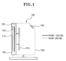
- FIG. 1 is a cross-sectional view showing an interior of a PDP having a conventional heat transfer apparatus.
- a PDP 100 having a conventional heat transfer apparatus comprises a filter 110, a panel 120, a heat sink (or radiating) plate 130, a fan 140, a front casing 150 and a rear casing 160.
- the filter 110 protects an image display apparatus such as the panel 120 from an external shock.
- the filter 110 is generally made from glass.
- the panel 120 consists of two base plates of glass formed typically with a gap of approximately 0.1mm therebetween. The gap between the two base plates is under vacuum, and there occurs a gas discharge phenomenon in the gap. Accordingly, the PDP 100 displays an image by utilizing the gas discharge phenomenon that occurs in the vacuous gap.
- the heat sink plate 130 On a rear surface of the panel 120 is provided the heat sink plate 130 for transferring heat away from the panel 120.
- the heat sink plate 130 is made from metallic plate of a high thermal conductivity such as aluminum.
- At a rear surface of the heat sink plate 130 is provided at least one fan 140 for cooling the panel 120 during the operation of the PDP 100.
- the PDP 100 When the PDP 100 is driven, heat is generated inside the panel 120 due to the gas discharge phenomenon. Most of the generated heat is conducted to the heat sink plate 130 disposed at the rear surface of the panel 120.
- the fan 140 circulates the inner air of the PDP 100 to cool the heat sink plate 130.
- the heat sink plate 130 is cooled by a natural convection caused by a temperature difference.
- Figure 1 shows the front casing 150 in a thick solid line and the rear casing 160 in a dotted line.
- the front casing 150 is disposed at a front surface of the PDP 100 where the filter 110 is disposed and the rear casing 160 is typically disposed at a rear surface of the PDP 100 where the fan 140 is disposed, thereby protecting the PDP 100 from an external shock.
- Figure 2 is an isothermal line showing a temperature distribution of the panel when the PDP is driven.
- the temperature distribution is irregular when the PDP 100 is driven and there is a great temperature difference between the upper end and the lower end. The temperature difference increases as the panel 120 is enlarged in size.
- the temperature difference of the panel 120 shortens the life span of the PDP 100, and the upper end and the lower end have different capacities such that an even quality of image cannot be obtained.
- the temperature difference between the upper end and the lower end of the panel 120 increases.
- the PDP 100 comprises the fan 140 for cooling the PDP 100, it is difficult to make the PDP 100 thinner. Additionally, power consumption is increased, and there is a problem of noise.
- a display apparatus is characterised by temperature equalisation means for equalising the temperature of said display panel.
- the temperature equalisation means comprises a loop heat pipe. More preferably, the loop heat pipe contains a small amount of fluid and the inside of the loop heat pipe is under vacuum.
- the heat transfer means comprises a heat sink plate and the loop heat pipe is disposed along the margin of a major face of the heat sink plate.
- the loop heat pipe has a meandering portion between the evaporator section and the condenser section.
- an image display apparatus 300 comprises an image display unit 310, a heat sink plate 320 and a heat transmission unit 330.
- the image display unit 310 uses a plasma display panel (PDP), a liquid crystal display (LCD) or another type of flat panel display now known or in the future discovered suitable for use with the present invention.
- the image display unit 310 of the present example uses a PDP.
- the heat sink plate 320 is attached to a rear surface of the PDP 310.
- the heat sink plate 320 is typically made of metallic material such as aluminum that has a high thermal conductivity.
- On the heat sink plate 320 is provided the heat transmission unit 330.
- the heat transmission unit 330 uses a loop heat pipe 330. As shown in Figure 3, the loop heat pipe 330 forms a closed loop and is disposed in the margin of a major face of the heat sink plate 320.
- the loop heat pipe 330 be formed symmetrically with respect to vertical and horizontal centre lines of the heat sink plate 320.
- the loop heat pipe 330 can be shaped as a circle, an ellipse, or a polygon such as a triangle and a square.
- the loop heat pipe 330 can be formed all over the heat sink plate 320 in a meandering or zigzag fashion.
- the meandering fashion of the loop heat pipe 330 allows the PDP 310 to be protected from an external shock and helps the loop heat pipe 330 and the PDP 310 to have a regular temperature.
- the meandering pattern shown in Figure 4 is but one illustrative type of many meandering patterns that may be used.
- the meandering pattern of Figure 4 is not symmetrical with respect to both the horizontal and vertical centre lines of the heat sink plate 320.
- the loop heat pipe 330 is a heat transfer apparatus that moves a large amount of heat by utilizing the latent heat of vaporisation of an operation fluid (sometimes called a working fluid) in the loop heat pipe 330, even with a small temperature difference and regardless of gravity.
- the operation fluid uses material such as distilled water or another suitable liquid that is phase-changeable according to the temperature.
- the inside of the loop heat pipe 330 is under vacuum.
- the loop heat pipe 330 comprises an evaporator section 332, a first adiabatic section 334, a condenser section 336 and a second adiabatic section 338.
- the PDP 310 When the image display apparatus 300 is driven, the PDP 310 generates heat. For the same reason as described above, the upper end of the PDP 310 has a higher temperature than the lower end. That is, the upper end of the PDP 310 becomes a heat source for the loop heat pipe 330. It is preferred that the operation fluid is placed at an opposite position to the heat source.
- the heat source is in thermal contact with the evaporator 332, and a small amount of the operation fluid injected into the evaporator 332 boils due to the heat transferred from the upper end of the PDP 310, i.e., the heat source. Since the loop heat pipe 330 is under vacuum, the operation fluid is easy to boil even with a small temperature difference. The operation fluid evaporated by the heat source spreads inside the loop heat pipe 330.
- the evaporated operation fluid passes along the first adiabatic section 334 and condenses at the condenser 336, giving up the latent heat of vaporisation of the operation fluid to the condenser 336.
- the liquefied operation fluid passes along the second adiabatic section 338 and returns to the evaporator 332, which is in thermal contact with the heat source.
- the heat is transferred. That is, the operation fluid continually circulates in the loop heat pipe 330 through the repeated evaporation and liquefaction by the heat source.
- the operation fluid When the operation fluid reaches its boiling point, the liquid and vapor of the operation fluid maintain an equal temperature.
- the liquid and vapor is changed and moved at a high speed in the loop heat pipe 330. Accordingly, the loop heat pipe 330 maintains the equal inner temperature due to the speedy movement of the liquid and vapor of the operation fluid.
- the surface temperature of the PDP 310 is equalized. Also, the operation fluid moves at high speed such that the PDP 310 maintains the equalized temperature without an extreme temperature change.
- the evaporated operation fluid can be transferred by a greater distance. Since the loop heat pipe 330 is able to transfer heat in the opposite direction to the force of gravity, which differs from a conventional heat pipe, it is also able to transfer the heat from the upper end of the PDP 310 to the lower end. Accordingly, even with the PDP 310 being enlarged and the loop heat pipe 330 having a long length, the operation fluid maintains its heat transfer rate, and thus, the enlarged PDP 310 can have its temperature equalized.
- the image display apparatus that uses a panel such as the PDP, the LCD or the like is provided with the loop heat pipe, such that the extreme temperature difference between the upper and lower ends of the panel is reduced and the temperature of the panel is equalized.
- the partial damage to the panel that may be caused by the high temperature heat generated from a certain part of the panel can be prevented, and accordingly, the life span of the panel can be extended.
- the equalized temperature of the panel can reduce a brightness difference between the upper and lower ends of the panel.
Landscapes
- Physics & Mathematics (AREA)
- Nonlinear Science (AREA)
- Engineering & Computer Science (AREA)
- Crystallography & Structural Chemistry (AREA)
- Mathematical Physics (AREA)
- Chemical & Material Sciences (AREA)
- Microelectronics & Electronic Packaging (AREA)
- Thermal Sciences (AREA)
- General Physics & Mathematics (AREA)
- Optics & Photonics (AREA)
- Multimedia (AREA)
- Signal Processing (AREA)
- Devices For Indicating Variable Information By Combining Individual Elements (AREA)
- Cooling Or The Like Of Electrical Apparatus (AREA)
Abstract
Description
Claims (10)
- An image display apparatus (300) comprising a display panel (310) and heat transfer means (320) for conducting heat away from the display panel (310), characterised by temperature equalisation means (330) for equalising the temperature of said display panel (310).
- An apparatus according to claim 1, wherein the temperature equalisation means (330) comprises a loop heat pipe.
- An apparatus according to claim 2, wherein the loop heat pipe (330) contains a small amount of fluid and the inside of the loop heat pipe is (330) under vacuum.
- An apparatus according to claims 2 or 3, wherein the heat transfer means (320) comprises a heat sink plate and the loop heat pipe (330) is disposed along the margin of a major face of the heat sink plate.
- An apparatus according to claims 2 or 3, wherein the loop heat pipe (330) has a meandering portion between an evaporator section (332) and a condenser section (336) thereof.
- An image display apparatus (300) comprising:an image display unit (310) for displaying an image on a screen; anda radiating plate (320) having a heat transmission unit (330) for equalizing a surface temperature of the image display unit by circulating heat emitted from the image display unit (310).
- The image display apparatus of claim 6, wherein the heat transmission unit (330) is a loop heat pipe.
- The image display apparatus of claim 7, wherein the loop heat pipe (330) has inside a small amount of operation fluid, the inside of the loop heat pipe (330) being under vacuum.
- The image display apparatus of claim 6, wherein the heat transmission unit (330) is shaped in a closed loop and is disposed around an edge of the radiating plate (320).
- The image display apparatus of claim 6, wherein the heat transmission unit (330) is shaped in a closed loop and is formed in a zigzag fashion.
Applications Claiming Priority (2)
| Application Number | Priority Date | Filing Date | Title |
|---|---|---|---|
| KR10-2002-0002432A KR100446084B1 (en) | 2002-01-16 | 2002-01-16 | Image display apparatus |
| KR2002002432 | 2002-01-16 |
Publications (2)
| Publication Number | Publication Date |
|---|---|
| EP1329934A2 true EP1329934A2 (en) | 2003-07-23 |
| EP1329934A3 EP1329934A3 (en) | 2005-08-31 |
Family
ID=36717143
Family Applications (1)
| Application Number | Title | Priority Date | Filing Date |
|---|---|---|---|
| EP03250265A Ceased EP1329934A3 (en) | 2002-01-16 | 2003-01-16 | Image display apparatus |
Country Status (5)
| Country | Link |
|---|---|
| US (1) | US6774544B2 (en) |
| EP (1) | EP1329934A3 (en) |
| JP (1) | JP2003280531A (en) |
| KR (1) | KR100446084B1 (en) |
| CN (1) | CN1252779C (en) |
Cited By (1)
| Publication number | Priority date | Publication date | Assignee | Title |
|---|---|---|---|---|
| GB2403025B (en) * | 2003-06-20 | 2005-11-16 | Hitachi Ltd | Liquid crystal projector having a cooling apparatus |
Families Citing this family (16)
| Publication number | Priority date | Publication date | Assignee | Title |
|---|---|---|---|---|
| KR100528917B1 (en) * | 2003-07-22 | 2005-11-15 | 삼성에스디아이 주식회사 | Plasma display device |
| JP4631330B2 (en) * | 2004-07-05 | 2011-02-16 | ソニー株式会社 | Image display device |
| CN100368884C (en) * | 2004-08-17 | 2008-02-13 | 友达光电股份有限公司 | Temperature compensation structure and method for liquid crystal display assembly |
| KR101090068B1 (en) * | 2005-01-05 | 2011-12-07 | 삼성전자주식회사 | Rotation detection device and display device and display system including same |
| US7771095B2 (en) * | 2005-10-26 | 2010-08-10 | Abl Ip Holding, Llc | Lamp thermal management system |
| US7438440B2 (en) * | 2006-04-25 | 2008-10-21 | Abl Ip Holding Llc | Lamp thermal management system |
| KR100837164B1 (en) * | 2006-08-10 | 2008-06-11 | 엘지전자 주식회사 | Video display |
| JP5202220B2 (en) * | 2008-09-30 | 2013-06-05 | 三洋電機株式会社 | Image display device |
| JP5268679B2 (en) * | 2009-01-29 | 2013-08-21 | 三洋電機株式会社 | Image display device |
| JP2014105923A (en) * | 2012-11-27 | 2014-06-09 | Mitsubishi Heavy Ind Ltd | Missile |
| ES2604905T3 (en) * | 2012-12-19 | 2017-03-09 | Premium Electronic Co., Limited | Display device |
| KR102081928B1 (en) * | 2013-04-24 | 2020-02-26 | 엘지전자 주식회사 | Digital signage |
| JP6229465B2 (en) * | 2013-12-06 | 2017-11-15 | 富士通株式会社 | Display panel |
| KR102730876B1 (en) * | 2019-06-04 | 2024-11-18 | 삼성전자주식회사 | Display apparatus |
| KR102804063B1 (en) * | 2020-12-28 | 2025-05-09 | 엘지디스플레이 주식회사 | Organic light emitting display device |
| KR20240083964A (en) * | 2022-12-05 | 2024-06-13 | 삼성디스플레이 주식회사 | Display device |
Family Cites Families (14)
| Publication number | Priority date | Publication date | Assignee | Title |
|---|---|---|---|---|
| US5132585A (en) * | 1990-12-21 | 1992-07-21 | Motorola, Inc. | Projection display faceplate employing an optically transmissive diamond coating of high thermal conductivity |
| KR100321810B1 (en) * | 1994-09-16 | 2002-06-20 | 타나카 시게노부 | Personal computer cooler with hinged heat pipe |
| JPH08179836A (en) * | 1994-12-20 | 1996-07-12 | Fujitsu General Ltd | Display cooling system |
| JPH0922013A (en) * | 1995-07-05 | 1997-01-21 | Mitsubishi Electric Corp | Liquid crystal projector and manufacturing method thereof |
| JP3885246B2 (en) * | 1996-01-12 | 2007-02-21 | 松下電器産業株式会社 | Plasma display panel |
| US5971566A (en) * | 1996-07-23 | 1999-10-26 | Matsushita Electric Industrial Co., Ltd. | Plasma display device and its manufacturing method |
| JPH1165459A (en) * | 1997-08-20 | 1999-03-05 | Fujitsu General Ltd | PDP heat dissipation device |
| JPH11251777A (en) * | 1998-03-06 | 1999-09-17 | Fujitsu General Ltd | Plasma display device |
| JP3747306B2 (en) * | 1998-03-25 | 2006-02-22 | 株式会社日立プラズマパテントライセンシング | Plasma display device |
| JPH11327449A (en) * | 1998-05-13 | 1999-11-26 | Mitsubishi Electric Corp | Plasma display device |
| JPH11338582A (en) * | 1998-05-29 | 1999-12-10 | Mitsubishi Electric Corp | Information processing device |
| JP2000132280A (en) * | 1998-10-23 | 2000-05-12 | Showa Alum Corp | Radiator for portable electronic equipment |
| JP2000222070A (en) * | 1999-01-29 | 2000-08-11 | Mitsubishi Electric Corp | Information equipment |
| JP2001282114A (en) * | 2000-03-30 | 2001-10-12 | Hitachi Ltd | Plasma display device |
-
2002
- 2002-01-16 KR KR10-2002-0002432A patent/KR100446084B1/en not_active Expired - Fee Related
- 2002-10-30 US US10/283,137 patent/US6774544B2/en not_active Expired - Fee Related
- 2002-11-08 JP JP2002325311A patent/JP2003280531A/en active Pending
- 2002-11-25 CN CNB021528357A patent/CN1252779C/en not_active Expired - Fee Related
-
2003
- 2003-01-16 EP EP03250265A patent/EP1329934A3/en not_active Ceased
Cited By (2)
| Publication number | Priority date | Publication date | Assignee | Title |
|---|---|---|---|---|
| GB2403025B (en) * | 2003-06-20 | 2005-11-16 | Hitachi Ltd | Liquid crystal projector having a cooling apparatus |
| US6991335B2 (en) | 2003-06-20 | 2006-01-31 | Hitachi, Ltd. | Liquid crystal projector |
Also Published As
| Publication number | Publication date |
|---|---|
| JP2003280531A (en) | 2003-10-02 |
| KR20030062038A (en) | 2003-07-23 |
| CN1433040A (en) | 2003-07-30 |
| EP1329934A3 (en) | 2005-08-31 |
| US6774544B2 (en) | 2004-08-10 |
| CN1252779C (en) | 2006-04-19 |
| US20030132710A1 (en) | 2003-07-17 |
| KR100446084B1 (en) | 2004-08-30 |
Similar Documents
| Publication | Publication Date | Title |
|---|---|---|
| EP1329934A2 (en) | Image display apparatus | |
| EP1383369B1 (en) | Thermosiphon for electronics cooling with high performance boiling and condensing surfaces | |
| US7101055B2 (en) | Direct back light unit with heat exchange | |
| US20120038849A1 (en) | Expanded Heat Sink for Electronic Displays and Method of Producing the Same | |
| US20050093140A1 (en) | Heat spreader, heat sink, heat exchanger and PDP chassis base | |
| EP3618595B1 (en) | Heat dissipation system for liquid crystal television, and liquid crystal television | |
| US20050077822A1 (en) | Plasma display panel and plasma display device having the same | |
| US20050046618A1 (en) | Plasma display module with improved heat dissipation characteristics | |
| TW200904308A (en) | Display device | |
| US7561426B2 (en) | Display module | |
| JP2011133712A (en) | Electronic signboard and cooling control method for the same | |
| US20060203445A1 (en) | Heat-dissipating structure for flat panel display | |
| US11873982B2 (en) | Vapor chamber element | |
| CN101339306A (en) | display device | |
| KR100669366B1 (en) | Plasma display device with porous heat transfer sheet | |
| JP2003214742A (en) | Cooling storage for glass substrate | |
| KR100492707B1 (en) | Cooling means of pdp(plasma display panel) | |
| JPH1124575A (en) | Plasma display panel device | |
| KR100495991B1 (en) | Heat sink device of a plasma display panel | |
| JP2007101783A (en) | Plasma display device | |
| TW388202B (en) | Cold plate heat dissipating module of micro heat pipe for color plasma display | |
| RU94271U1 (en) | THERMAL INSULATION DEVICE | |
| JP2011180181A (en) | Electronic signboard | |
| KR20060098460A (en) | Plasma display device | |
| KR20060086211A (en) | Plasma display module |
Legal Events
| Date | Code | Title | Description |
|---|---|---|---|
| PUAI | Public reference made under article 153(3) epc to a published international application that has entered the european phase |
Free format text: ORIGINAL CODE: 0009012 |
|
| AK | Designated contracting states |
Designated state(s): AT BE BG CH CY CZ DE DK EE ES FI FR GB GR HU IE IT LI LU MC NL PT SE SI SK TR |
|
| AX | Request for extension of the european patent |
Extension state: AL LT LV MK RO |
|
| RAP1 | Party data changed (applicant data changed or rights of an application transferred) |
Owner name: SAMSUNG ELECTRONICS CO., LTD. |
|
| PUAL | Search report despatched |
Free format text: ORIGINAL CODE: 0009013 |
|
| AK | Designated contracting states |
Kind code of ref document: A3 Designated state(s): AT BE BG CH CY CZ DE DK EE ES FI FR GB GR HU IE IT LI LU MC NL PT SE SI SK TR |
|
| AX | Request for extension of the european patent |
Extension state: AL LT LV MK RO |
|
| RIC1 | Information provided on ipc code assigned before grant |
Ipc: 7H 01J 7/28 B Ipc: 7H 01J 17/28 B Ipc: 7G 02F 1/133 A |
|
| 17P | Request for examination filed |
Effective date: 20060119 |
|
| AKX | Designation fees paid |
Designated state(s): DE GB NL |
|
| STAA | Information on the status of an ep patent application or granted ep patent |
Free format text: STATUS: THE APPLICATION HAS BEEN REFUSED |
|
| 18R | Application refused |
Effective date: 20081023 |