EP1329905A2 - Method of surface-treating reactor member and method of manufacturing reactor member by using the surface treatment method - Google Patents
Method of surface-treating reactor member and method of manufacturing reactor member by using the surface treatment method Download PDFInfo
- Publication number
- EP1329905A2 EP1329905A2 EP02015569A EP02015569A EP1329905A2 EP 1329905 A2 EP1329905 A2 EP 1329905A2 EP 02015569 A EP02015569 A EP 02015569A EP 02015569 A EP02015569 A EP 02015569A EP 1329905 A2 EP1329905 A2 EP 1329905A2
- Authority
- EP
- European Patent Office
- Prior art keywords
- reactor member
- work
- layer
- bending
- hardened layer
- Prior art date
- Legal status (The legal status is an assumption and is not a legal conclusion. Google has not performed a legal analysis and makes no representation as to the accuracy of the status listed.)
- Granted
Links
- 238000000034 method Methods 0.000 title claims abstract description 31
- 238000004381 surface treatment Methods 0.000 title claims description 22
- 238000004519 manufacturing process Methods 0.000 title claims description 9
- 230000002950 deficient Effects 0.000 claims abstract description 42
- 238000010438 heat treatment Methods 0.000 claims abstract description 25
- 238000005452 bending Methods 0.000 claims abstract description 24
- 239000002826 coolant Substances 0.000 claims abstract description 15
- 238000003754 machining Methods 0.000 claims abstract description 14
- 238000005422 blasting Methods 0.000 claims abstract description 10
- 239000002253 acid Substances 0.000 claims abstract description 7
- 238000005520 cutting process Methods 0.000 claims abstract description 7
- 238000005498 polishing Methods 0.000 claims abstract description 7
- 238000007747 plating Methods 0.000 claims abstract description 6
- 239000000446 fuel Substances 0.000 claims description 15
- 230000003746 surface roughness Effects 0.000 claims description 6
- XLYOFNOQVPJJNP-UHFFFAOYSA-N water Substances O XLYOFNOQVPJJNP-UHFFFAOYSA-N 0.000 claims description 6
- 238000005260 corrosion Methods 0.000 abstract description 12
- 238000005336 cracking Methods 0.000 abstract description 12
- 239000010410 layer Substances 0.000 description 59
- 239000011651 chromium Substances 0.000 description 37
- 230000032683 aging Effects 0.000 description 7
- 238000010586 diagram Methods 0.000 description 7
- 239000000463 material Substances 0.000 description 7
- 239000002344 surface layer Substances 0.000 description 5
- 238000012360 testing method Methods 0.000 description 3
- 238000004458 analytical method Methods 0.000 description 2
- QVGXLLKOCUKJST-UHFFFAOYSA-N atomic oxygen Chemical compound [O] QVGXLLKOCUKJST-UHFFFAOYSA-N 0.000 description 2
- 239000011324 bead Substances 0.000 description 2
- 230000000694 effects Effects 0.000 description 2
- 238000000921 elemental analysis Methods 0.000 description 2
- 239000011521 glass Substances 0.000 description 2
- 239000001301 oxygen Substances 0.000 description 2
- 229910052760 oxygen Inorganic materials 0.000 description 2
- 238000003825 pressing Methods 0.000 description 2
- 238000012545 processing Methods 0.000 description 2
- 230000035882 stress Effects 0.000 description 2
- UFHFLCQGNIYNRP-UHFFFAOYSA-N Hydrogen Chemical compound [H][H] UFHFLCQGNIYNRP-UHFFFAOYSA-N 0.000 description 1
- GRYLNZFGIOXLOG-UHFFFAOYSA-N Nitric acid Chemical compound O[N+]([O-])=O GRYLNZFGIOXLOG-UHFFFAOYSA-N 0.000 description 1
- WGLPBDUCMAPZCE-UHFFFAOYSA-N Trioxochromium Chemical compound O=[Cr](=O)=O WGLPBDUCMAPZCE-UHFFFAOYSA-N 0.000 description 1
- 238000007545 Vickers hardness test Methods 0.000 description 1
- 230000002411 adverse Effects 0.000 description 1
- 229910045601 alloy Inorganic materials 0.000 description 1
- 239000000956 alloy Substances 0.000 description 1
- 229910000423 chromium oxide Inorganic materials 0.000 description 1
- 230000002301 combined effect Effects 0.000 description 1
- 238000007796 conventional method Methods 0.000 description 1
- 239000000498 cooling water Substances 0.000 description 1
- 230000007797 corrosion Effects 0.000 description 1
- 230000007423 decrease Effects 0.000 description 1
- 230000002542 deteriorative effect Effects 0.000 description 1
- 238000009826 distribution Methods 0.000 description 1
- 238000010891 electric arc Methods 0.000 description 1
- 238000000866 electrolytic etching Methods 0.000 description 1
- 238000005530 etching Methods 0.000 description 1
- 239000001257 hydrogen Substances 0.000 description 1
- 229910052739 hydrogen Inorganic materials 0.000 description 1
- 229910000816 inconels 718 Inorganic materials 0.000 description 1
- 238000005259 measurement Methods 0.000 description 1
- 229910052751 metal Inorganic materials 0.000 description 1
- 239000002184 metal Substances 0.000 description 1
- 229910017604 nitric acid Inorganic materials 0.000 description 1
- 230000002265 prevention Effects 0.000 description 1
Images



Classifications
-
- G—PHYSICS
- G21—NUCLEAR PHYSICS; NUCLEAR ENGINEERING
- G21C—NUCLEAR REACTORS
- G21C3/00—Reactor fuel elements and their assemblies; Selection of substances for use as reactor fuel elements
- G21C3/02—Fuel elements
- G21C3/04—Constructional details
- G21C3/06—Casings; Jackets
- G21C3/07—Casings; Jackets characterised by their material, e.g. alloys
-
- G—PHYSICS
- G21—NUCLEAR PHYSICS; NUCLEAR ENGINEERING
- G21C—NUCLEAR REACTORS
- G21C3/00—Reactor fuel elements and their assemblies; Selection of substances for use as reactor fuel elements
- G21C3/02—Fuel elements
- G21C3/04—Constructional details
- G21C3/06—Casings; Jackets
- G21C3/12—Means forming part of the element for locating it within the reactor core
-
- Y—GENERAL TAGGING OF NEW TECHNOLOGICAL DEVELOPMENTS; GENERAL TAGGING OF CROSS-SECTIONAL TECHNOLOGIES SPANNING OVER SEVERAL SECTIONS OF THE IPC; TECHNICAL SUBJECTS COVERED BY FORMER USPC CROSS-REFERENCE ART COLLECTIONS [XRACs] AND DIGESTS
- Y02—TECHNOLOGIES OR APPLICATIONS FOR MITIGATION OR ADAPTATION AGAINST CLIMATE CHANGE
- Y02E—REDUCTION OF GREENHOUSE GAS [GHG] EMISSIONS, RELATED TO ENERGY GENERATION, TRANSMISSION OR DISTRIBUTION
- Y02E30/00—Energy generation of nuclear origin
- Y02E30/30—Nuclear fission reactors
-
- Y—GENERAL TAGGING OF NEW TECHNOLOGICAL DEVELOPMENTS; GENERAL TAGGING OF CROSS-SECTIONAL TECHNOLOGIES SPANNING OVER SEVERAL SECTIONS OF THE IPC; TECHNICAL SUBJECTS COVERED BY FORMER USPC CROSS-REFERENCE ART COLLECTIONS [XRACs] AND DIGESTS
- Y10—TECHNICAL SUBJECTS COVERED BY FORMER USPC
- Y10S—TECHNICAL SUBJECTS COVERED BY FORMER USPC CROSS-REFERENCE ART COLLECTIONS [XRACs] AND DIGESTS
- Y10S148/00—Metal treatment
- Y10S148/902—Metal treatment having portions of differing metallurgical properties or characteristics
- Y10S148/908—Spring
-
- Y—GENERAL TAGGING OF NEW TECHNOLOGICAL DEVELOPMENTS; GENERAL TAGGING OF CROSS-SECTIONAL TECHNOLOGIES SPANNING OVER SEVERAL SECTIONS OF THE IPC; TECHNICAL SUBJECTS COVERED BY FORMER USPC CROSS-REFERENCE ART COLLECTIONS [XRACs] AND DIGESTS
- Y10—TECHNICAL SUBJECTS COVERED BY FORMER USPC
- Y10S—TECHNICAL SUBJECTS COVERED BY FORMER USPC CROSS-REFERENCE ART COLLECTIONS [XRACs] AND DIGESTS
- Y10S376/00—Induced nuclear reactions: processes, systems, and elements
- Y10S376/90—Particular material or material shapes for fission reactors
Definitions
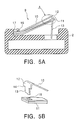
- Fig. 5B is an enlarged detailed diagram of a portion A surrounded by the dotted line in Fig. 5A.
- the upper spring 10 has a curved portion 12 and a vertical portion 13, and the vertical portion 13 has stepped edges 14.
- the lower spring 11 has a through hole 15.
- the upper spring 10 and the lower spring 11 are combined in an integrated structure such that the vertical portion 13 of the upper spring 10 is passed through the through hole 15, and the upper spring 10 contacts the lower spring 11 with the stepped edges 14 of the vertical portion 13.
- the surface layer is removed by performing wet blasting characterized by the combined effect of water + grinding material + air (compressed air) instead of glass bead blasting (GBB), which is dry blasting.
- the surface layer in the region of the leaf spring designated as a portion to be worked is removed by laser irradiation.
Landscapes
- Engineering & Computer Science (AREA)
- Physics & Mathematics (AREA)
- Plasma & Fusion (AREA)
- General Engineering & Computer Science (AREA)
- High Energy & Nuclear Physics (AREA)
- Metallurgy (AREA)
- Springs (AREA)
- Heat Treatment Of Articles (AREA)
- Electroplating Methods And Accessories (AREA)
Abstract
Description
- The present invention relates to a fuel assembly for use in a pressurized water reactor and, more particularly, to a method of surface-treating a leaf spring provided on an upper nozzle.
- Fig. 4 is a diagram schematically showing a fuel assembly ordinarily used in pressurized water reactors, and Figs. 5A and 5B are diagrams schematically showing a leaf spring. Referring to Fig. 4, the
fuel assembly 1 is constituted by anupper nozzle 2, alower nozzle 3, a plurality ofgrids 4, controlrod guide tubes 5, and a multiplicity offuel rods 6. More specifically, theupper nozzle 2 and thelower nozzle 3 are placed spaced apart from each other in the vertical direction, and a plurality ofgrids 4 are placed at certain intervals between the upper andlower nozzles grid 4 has grid spaces formed by straps. The controlrod guide tubes 5 are inserted in the grid spaces at predetermined positions and are fixed by fixing portions of thegrid 4. The upper and lower ends of the controlrod guide tubes 5 are connected to the upper andlower nozzles fuel rods 6 are elastically supported by supporting portions of thegrids 4. Thefuel assembly 1 is held in a core (not shown) by anupper core plate 7 and alower core plate 8 of an in-reactor structure. - A
leaf spring 9 is provided on theupper nozzle 2 by being interposed between theupper nozzle 2 and theupper core plate 7. Theleaf spring 9 has the function of absorbing elongation of thefuel assembly 1 caused by irradiation as well as the differences in thermal expansion between thefuel assembly 1 and the in-reactor structure, and also has the function of preventing thefuel assembly 1 from being floated by cooling water flowing in from below. - There are certain types of
fuel assembly 1 ordinarily used, e.g., the 17 x 17 type, the 15 × 15 type, and the 14 x 14 type selected according to the number offuel rods 6 arrayed. Figs. 5A and 5B illustrate the structure of an example of the 17 × 17 type ofleaf spring 9. Theleaf spring 9 is formed of anupper spring 10 and alower spring 11. Thelower spring 11 is formed of two plate members. - Fig. 5B is an enlarged detailed diagram of a portion A surrounded by the dotted line in Fig. 5A. As can be seen in Figs. 5A and 5B, the
upper spring 10 has acurved portion 12 and avertical portion 13, and thevertical portion 13 hasstepped edges 14. Thelower spring 11 has a throughhole 15. Theupper spring 10 and thelower spring 11 are combined in an integrated structure such that thevertical portion 13 of theupper spring 10 is passed through the throughhole 15, and theupper spring 10 contacts thelower spring 11 with thestepped edges 14 of thevertical portion 13. - The
leaf spring 9 has abase portion 16 formed in a horizontal structure for fixation on theupper nozzle 2, that is, thebase portion 16 is parallel to an upper surface of theupper nozzle 2. Theleaf spring 9 is fixed on theupper nozzle 2 with thebase portion 16 fastened to theupper nozzle 2 by anattachment bolt 17. Theleaf spring 9 is formed so that its upper end (in the vicinity of the curved portion 12) is brought into contact with theupper core plate 7 to produce a pressing force. Theleaf spring 9 is therefore bent upwardly at a comparatively large angle in the vicinity of thebase portion 16. A precipitation-hardened alloy of a high proof stress (e.g., Inconel 718) is used as the material of theleaf spring 9 in order to obtain the necessary spring force. - Ordinarily, the
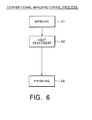
fuel assembly 1 is used in a reactor while being immersed in a primary coolant. In theleaf spring 9, stress is caused during use in the reactor. There is a possibility of stress-corrosion cracking (SCC) caused in theleaf spring 9 by high temperature primary coolant. Also, it is thought that the state of the surface of the leaf spring material in contact with the primary coolant influences stress-corrosion cracking (SCC). - A conventional leaf spring manufacturing process under the above-described circumstances will be briefly described with reference to Fig. 6. Since as mentioned above the
base portion 16 of theleaf spring 9 is fixed on theupper nozzle 2, thebase portion 16 must be provided in a horizontal structure. On the other hand, the upper end of theleaf spring 9 is shaped so as to be suitable for contact with theupper core plate 7 in producing the necessary pressing force. Accordingly, bending (step 1) is performed to bend thebase portion 16 of theleaf spring 9 upward. In this bending process, the leaf spring is bent so as to have a comparatively large angle. Therefore, it is necessary, from the viewpoint of workability, to perform bending before heat treatment (step 2). - However, if bending is performed before the heat treatment, there is a problem that an oxide film formed by the heat treatment attaches to the bent portion to form a Cr-deficient layer. Ordinarily, this oxide film is removed by grinding the surface. However, it is extremely difficult to remove the oxide film by grinding based on ordinary grinding methods since this grinding is performed after bending (step 1). Therefore, the bent portion is presently left in its unground state. Consequently, therefore, in addition to the work-hardened layer remaining after bending, a Cr-deficient layer is formed in the bent portion due to the oxide film. Accordingly, there is a possibility of the
leaf spring 9 stress-corrosion cracking resistance characteristics (SCC resistance characteristics) deteriorating due to such layers. - As a method for surface treatment of the
leaf spring 9, a method has been used in which the oxide film is removed by glass bead blasting (GBB) to obtain an improved appearance of the product after a final machining step (step 3) following the heat treatment (step 2). However, it is difficult to remove the Cr-deficient layer in the metallic portion by this GBB. Stronger GBB entails the risk of newly forming a work-hardened layer and is therefore undesirable. - The points in the above are potential factors to be a cause of stress-corrosion cracking (SCC) under a low-stress condition. That is, the Cr-deficient layer reduces the corrosion resistance of the surface, while the surface work-hardened layer increases the possibility of early cracking.
- In view of the above-described problems of the conventional art, an object of the present invention is to provide a method of surface-treating a reactor member so that the Cr-deficient layer and the work-hardened layer formed as surface layers are effectively removed.
- In order to attain the above-mentioned object, according to a first aspect of the present invention, in a method of performing a surface treatment on a reactor member which is worked by bending and then processed by a heat treatment, in which a work-hardened layer is formed by the bending, and in which a Cr-deficient layer is formed due to an oxide film attached by the heat treatment, the method is characterized by using at least one of: acid wash; grinding; electrolytic polishing; electro-discharge machining; surface cutting; surface deoxidation and softening; wet blasting; and laser machining to remove the work-hardened layer and the Cr-deficient layer from the reactor member.
- According to a second aspect of the present invention, in a method of performing a surface treatment on a reactor member which is worked by bending and then processed by a heat treatment, in which a work-hardened layer is formed by the bending, and in which a Cr-deficient layer is formed due to an oxide film attached by the heat treatment, the method is characterized in that surface plating is performed to the reactor member to prevent contact of the work-hardened layer and the Cr-deficient layer of the reactor member with a primary coolant.
- It is possible to remove the Cr-deficient layer and the surface work-hardened layer in the surface of the reactor member or to prevent contact of the Cr-deficient layer and the work-hardened layer with the primary coolant by performing a surface treatment based on the surface working method formed as described above.
- The surface treatment is performed so that the amount of grinding is preferably in the range from 1 to 100 µm and the surface roughness is in the range of 0.1a to 0.4a. More preferably, the surface treatment is performed so that the amount of grinding is 75 µm and the surface roughness is 0.2a. As the reactor member to which the present invention is applied, a leaf spring placed on an upper nozzle of a fuel assembly for use in a pressurized water reactor is preferable.
- According to yet another aspect of the present invention, a method of manufacturing a reactor member is characterized by comprising: (i) a bending step for bending the reactor member through a predetermined angle; (ii) a heat treatment step for heat-treating the bent reactor member; (iii) a surface treatment step for removing a work-hardened layer formed by the bending and a Cr-deficient layer formed due to an oxide film attached by the heat treatment, or for preventing contact of the work-hardened layer and the Cr-deficient layer of the reactor member with a primary coolant; and (iv) a final fishing step for finishing the reactor member.
- It is possible to remove the Cr-deficient layer and the surface work-hardened layer in the member surface or to prevent contact of the Cr-deficient layer and the work-hardened layer with the primary coolant by performing a surface treatment based on the surface working method formed as described above. The reactor member thus finished is resistant to stress-corrosion cracking.
- The surface treatment step for removing the Cr-deficient layer formed due to the oxide film attached by the heat treatment is preferably one of: acid wash; grinding; electrolytic polishing; electro-discharge machining; surface cutting; surface deoxidation and softening; wet blasting; and laser machining. Further, the surface treatment step for preventing contact of the work-hardened layer and the Cr-deficient layer of the reactor member with the primary coolant is preferably surface plating.
-
- Fig. 1 is a diagram showing a manufacturing process in accordance with the present invention;
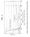
- Fig. 2 is a graph showing the results of elemental analysis performed on a leaf spring (bent portion) after aging treatment;
- Fig. 3 is a graph showing the result of measurement of measured results of hardness distribution in thickness direction of the leaf spring (bent portion) after aging treatment;
- Fig. 4 is a diagram schematically showing a fuel assembly ordinarily used in pressurized water reactors;
- Figs. 5A and 5B are diagrams schematically showing the leaf spring; and
- Fig. 6 is a diagram showing a conventional manufacturing process.
-
- A preferred embodiment of the present invention will be described with reference to the accompanying drawings. In the drawings, the same reference characters indicate the same or corresponding components.
- As described above, the process under the present circumstances causes a Cr-deficient layer and a work-hardened layer to remain in a bent portion of a worked member. To improve the stress-corrosion cracking resistance characteristics (SCC resistance characteristics) of the worked member, it is necessary to efficiently remove the Cr-deficient layer and the work-hardened layer. Conditions for grinding which are sufficiently effective in removing the Cr-deficient layer and the work-hardened layer without an adverse effect in terms of working cost were devised as grinding conditions in accordance with the present invention, as described below.
- Elemental analysis was first performed on the Cr-deficient layer with respect to the Cr concentration and the oxygen concentration after an aging treatment on the leaf spring. Fig. 2 shows the results of this analysis. Chromium oxide was produced in a 0.2 µm surface region. A state was observed in which both the Cr concentration and the oxygen concentration were high due to this oxide. It can be seen that the Cr concentration decreases abruptly at a position in the oxide region further from the surface, and that, with a further increase in the distance from the surface, the Cr concentration recovers gradually but is lower than that in the basic material. The region where the Cr concentration is low as described above has a depth of about 1 µm from the surface.
- As a test on the bending-work-hardened layer, a micro-Vickers hardness test was made with respect to the thickness direction of the spring cross-section after bending. Fig. 3 shows the results of this test. From these results, it can be understood that the hardness increased in a 50 µm region when the leaf spring was bent.
- The results of the two kinds of tests above show that the work-hardened layer is thicker than the Cr-deficient layer. Determination of grinding conditions from this viewpoint may suffice. Accordingly, to reliably grind the work-hardened layer, the amount of grinding may be set to 50 µm. However, there is a possibility of the work-hardened layer having a thickness smaller than 50 µm, depending on the degree of bending. For this reason, grinding is performed by at least an amount of 1 µm to cover the above-described low-Cr-concentration region.
- On the other hand, if the amount of grinding is large, the grinding time is considerably increased since the material is heat-treated before grinding to have a high hardness, resulting in an increase in manufacturing cost. Therefore a smaller grinding amount is preferred from the viewpoint of cost. Consequently, it is desirable to limit the amount of grinding to 100 µm or less.
- From the above analysis, the optimum values and ranges of the amount of grinding and the surface roughness after grinding are determined as shown below.
(Optimum value) (Range) Amount of grinding 75 µm 1 µm - 100 µm Surface roughness 0.2 a 0.1 a - 0.4 a - The inventor of the present invention has confirmed that leaf springs processed by grinding in the above-described range have improved stress-corrosion cracking resistance characteristics (SCC resistance characteristics) in comparison with those processed by the conventional method.
- According to the present invention, a surface treatment including the above-described grinding is performed before a finishing step to prevent occurrence of stress-corrosion cracking (SCC) in the leaf spring. Fig. 1 shows a leaf spring manufacturing process to which the present invention has been applied. As can be understood from Fig. 1, the difference from the conventional manufacturing process (see Fig. 6) resides in that a surface treatment including a grinding step (step 3) is performed between a heat treatment step (step 2) and a finishing step (step 4). Various surface working methods are listed below, each of which may be carried out with efficiency as a method for surface treatment of the leaf spring after the heat treatment so as to meet the above-described grinding conditions for working of the spring.
- The surface film after the aging treatment is removed by using nitric acid or the like. A surface portion of the leaf spring including a highly stressed portion in which stress-corrosion cracking (SCC) can easily occur is removed by being melted. To enable this, the amount of etching is controlled by controlling the acid concentration, processing time, temperature, and other factors.
- The surface film after the aging treatment is removed by grinding with a mechanical tool or grinding based on manual work. The shape and size after the heat treatment are measured to determine the amount of working on each portion to be worked, and the portion is worked by the determined amount. The shape of the grinding wheel and the tool used to perform grinding are changed with respect to the portions to be worked.
- The surface film after the aging treatment is removed by electrolytic etching. A direct current is caused to flow through an electrolytic polishing solution selected according to the metal, with the object of processing used as an anode, thereby dissolving the surface of the object.
- The surface film after the aging treatment is removed by electro-discharge machining. An electrode is made so as to conform to the shape of the leaf spring. The surface layer existing in the portion facing the electrode is removed by arc discharge.
- The entire surface of the leaf spring formed from a material in the form of a thick plate is shallowly cut to a predetermined size by wire cutting to remove the surface layer.
- The leaf spring is heated in a hydrogen atmosphere (reducing atmosphere) at such a low temperature that no heat treatment effect is produced, instead of undergoing the process of mechanically removing the Cr-deficient layer from the surface. Only a thin surface portion is thereby annealed to soften and to increase the ductility thereof to such an extent that the surface-work-hardened layer disappears. Also, the oxides in the leaf spring surface including Cr can be reduced to return Cr to the metallic basic material, thereby eliminating the Cr-deficient layer.
- The surface layer is removed by performing wet blasting characterized by the combined effect of water + grinding material + air (compressed air) instead of glass bead blasting (GBB), which is dry blasting.
- The surface layer in the region of the leaf spring designated as a portion to be worked is removed by laser irradiation.
- The leaf spring is plated to prevent contact of the Cr-deficient layer in the surface with the primary coolant.
- A surface treatment process based on one of the above-described nine kinds of surface working methods is performed after the heat treatment to remove the Cr-deficient layer or work-hardened layer in the leaf spring surface, which is considered to be the problem of the conventional art, or to prevent contact of the Cr-deficient layer and the work-hardened layer with the primary coolant. Consequently, occurrence of stress-corrosion cracking (SCC) in the leaf spring can be prevented.
Claims (8)
- A method of performing a surface treatment on a reactor member which is worked by bending and then processed by a heat treatment, in which a work-hardened layer is formed by the bending, and in which a Cr-deficient layer is formed due to an oxide film attached by the heat treatment,
said method comprising using at least one of: acid wash; grinding; electrolytic polishing; electro-discharge machining; surface cutting; surface deoxidation and softening; wet blasting; and laser machining to remove the work-hardened layer and the Cr-deficient layer from the reactor member. - A method of performing a surface treatment on a reactor member which is worked by bending and then processed by a heat treatment, in which a work-hardened layer is formed by the bending, and in which a Cr-deficient layer is formed due to an oxide film attached by the heat treatment,
said method comprising surface-plating the reactor member to prevent contact of the work-hardened layer and the Cr-deficient layer of the reactor member with a primary coolant. - A method of manufacturing a reactor member comprising:a bending step for bending the reactor member so as to have a predetermined angle;a heat treatment step for heat-treating the bent reactor member;a surface treatment step for removing a work-hardened layer formed by said bending and a Cr-deficient layer formed due to an oxide film attached by said heat treatment, or for preventing contact of the work-hardened layer and the Cr-deficient layer of the reactor member with a primary coolant; anda final finishing step for finishing the reactor member.
- A method according to claim 3, wherein said surface treatment step for removing the Cr-deficient layer formed due to the oxide film attached by said heat treatment comprises one of: acid wash; grinding; electrolytic polishing; electro-discharge machining; surface cutting; surface deoxidation and softening; wet blasting; and laser machining.
- A method according to claim 3, wherein said surface treatment step for preventing contact of the work-hardened layer and the Cr-deficient layer of the reactor member with the primary coolant comprises surface plating.
- A method according to any of claims 1 to 5, wherein the surface treatment is performed so that the amount of grinding is in the range from 1 to 100 µm and the surface roughness is in the range of 0.1a to 0.4a.
- A method according to claim 6, wherein the surface treatment is performed so that the amount of grinding is 75 µm and the surface roughness is 0.2a.
- A method according to any of the preceding claims, wherein the reactor member is a leaf spring placed on an upper nozzle of a fuel assembly for use in a pressurized water reactor.
Applications Claiming Priority (2)
| Application Number | Priority Date | Filing Date | Title |
|---|---|---|---|
| JP2002000667 | 2002-01-07 | ||
| JP2002000667A JP2003202391A (en) | 2002-01-07 | 2002-01-07 | Surface processing method for reactor member and production method for the reactor member using the surface processing method |
Publications (3)
| Publication Number | Publication Date |
|---|---|
| EP1329905A2 true EP1329905A2 (en) | 2003-07-23 |
| EP1329905A3 EP1329905A3 (en) | 2007-12-05 |
| EP1329905B1 EP1329905B1 (en) | 2010-09-08 |
Family
ID=19190527
Family Applications (1)
| Application Number | Title | Priority Date | Filing Date |
|---|---|---|---|
| EP02015569A Expired - Lifetime EP1329905B1 (en) | 2002-01-07 | 2002-07-12 | Method of surface-treating reactor member and method of manufacturing reactor member by using the surface treatment method |
Country Status (4)
| Country | Link |
|---|---|
| US (2) | US6869338B2 (en) |
| EP (1) | EP1329905B1 (en) |
| JP (1) | JP2003202391A (en) |
| DE (1) | DE60237576D1 (en) |
Families Citing this family (8)
| Publication number | Priority date | Publication date | Assignee | Title |
|---|---|---|---|---|
| JP2003202391A (en) * | 2002-01-07 | 2003-07-18 | Mitsubishi Heavy Ind Ltd | Surface processing method for reactor member and production method for the reactor member using the surface processing method |
| JP4471150B2 (en) * | 2003-11-05 | 2010-06-02 | Ntn株式会社 | Wheel bearing device and manufacturing method thereof |
| US8323072B1 (en) * | 2007-03-21 | 2012-12-04 | 3M Innovative Properties Company | Method of polishing transparent armor |
| US9660205B2 (en) * | 2007-06-22 | 2017-05-23 | Regents Of The University Of Colorado | Protective coatings for organic electronic devices made using atomic layer deposition and molecular layer deposition techniques |
| JP5149020B2 (en) * | 2008-01-23 | 2013-02-20 | 株式会社ディスコ | Wafer grinding method |
| US9062354B2 (en) | 2011-02-24 | 2015-06-23 | General Electric Company | Surface treatment system, a surface treatment process and a system treated component |
| KR101549397B1 (en) | 2014-05-08 | 2015-09-02 | 주식회사진영정기 | a manufacturing method of projecting parts of straps |
| CN106835171B (en) * | 2017-01-13 | 2019-07-09 | 安徽世强机械制造有限公司 | A kind of automobile wheel hub surface treatment process |
Family Cites Families (10)
| Publication number | Priority date | Publication date | Assignee | Title |
|---|---|---|---|---|
| US3345727A (en) * | 1965-04-20 | 1967-10-10 | Rockwell Standard Co | Method of making taper leaf springs |
| US4137131A (en) * | 1976-10-04 | 1979-01-30 | General Electric Company | Process for electrolytic deposition of metals on zirconium materials |
| US4672007A (en) * | 1984-08-16 | 1987-06-09 | Kollmorgen Technologies Corporation | Electrodeposition composition and process for providing a Zn/Si/P coating on metal substrates |
| JP2893098B2 (en) * | 1990-05-23 | 1999-05-17 | 原子燃料工業株式会社 | Method of manufacturing spacer plate for nuclear fuel |
| JP2560571B2 (en) * | 1991-07-15 | 1996-12-04 | 株式会社日立製作所 | Fuel channel box manufacturing method and fuel channel box |
| JPH05142372A (en) * | 1991-11-15 | 1993-06-08 | Nuclear Fuel Ind Ltd | Upper nozzle of fuel assembly for pressurized water reactor |
| US5577949A (en) * | 1993-07-20 | 1996-11-26 | C. Uyemura & Co., Ltd. | Buffing method |
| US6336269B1 (en) * | 1993-11-16 | 2002-01-08 | Benjamin N. Eldridge | Method of fabricating an interconnection element |
| JP3931447B2 (en) * | 1998-09-18 | 2007-06-13 | セイコーエプソン株式会社 | Metal sintered body and method for producing the same |
| JP2003202391A (en) * | 2002-01-07 | 2003-07-18 | Mitsubishi Heavy Ind Ltd | Surface processing method for reactor member and production method for the reactor member using the surface processing method |
-
2002
- 2002-01-07 JP JP2002000667A patent/JP2003202391A/en active Pending
- 2002-07-09 US US10/190,517 patent/US6869338B2/en not_active Expired - Fee Related
- 2002-07-12 EP EP02015569A patent/EP1329905B1/en not_active Expired - Lifetime
- 2002-07-12 DE DE60237576T patent/DE60237576D1/en not_active Expired - Lifetime
-
2005
- 2005-01-25 US US11/041,305 patent/US7459037B2/en not_active Expired - Fee Related
Non-Patent Citations (1)
| Title |
|---|
| None |
Also Published As
| Publication number | Publication date |
|---|---|
| EP1329905A3 (en) | 2007-12-05 |
| EP1329905B1 (en) | 2010-09-08 |
| US6869338B2 (en) | 2005-03-22 |
| US7459037B2 (en) | 2008-12-02 |
| DE60237576D1 (en) | 2010-10-21 |
| JP2003202391A (en) | 2003-07-18 |
| US20050220260A1 (en) | 2005-10-06 |
| US20030129929A1 (en) | 2003-07-10 |
Similar Documents
| Publication | Publication Date | Title |
|---|---|---|
| US8470106B2 (en) | Method of heat treatment for desensitizing a nickel-based alloy relative to environmentally-assisted cracking, in particular for a nuclear reactor fuel assembly and for a nuclear reactor, and a part made of the alloy and subjected to the treatment | |
| US6379476B1 (en) | Stainless steel product for producing polymer electrode fuel cell | |
| KR100382997B1 (en) | Method of Manufacturing A Tube and A Sheet of Niobium-containing Zirconium Alloys for High Burn-up Nuclear Fuel | |
| JP5109234B2 (en) | METAL MATERIAL FOR SOLID POLYMER TYPE FUEL CELL SEPARATOR, FUEL CELL SEPARATOR USING THE SAME, FUEL CELL, AND METHOD FOR ADJUSTING SURFACE Roughness of METAL MATERIAL FOR SOLID POLYMER TYPE FUEL CELL SEPARATOR | |
| US6869338B2 (en) | Method of surface-treating reactor member and method of manufacturing reactor member by using the surface treatment method | |
| US20120321904A1 (en) | High corrosion resistant equipment for a plant | |
| JPH01274929A (en) | Manufacturing method of steam turbine blade root | |
| WO2002014566A1 (en) | Nickel-based alloy product and process for producing the same | |
| EP1433864B1 (en) | Nickel alloy and manufacturing method for the same | |
| EP3068916B1 (en) | Nuclear fuel rod cladding including a metal nanomaterial layer | |
| EP2716778A1 (en) | Pure titanium sheet having excellent balance between press formability and strength and excellent corrosion resistance, and process for manufacturing same | |
| JP2009287104A (en) | Thin sheet of austenitic stainless steel and manufacturing method therefor | |
| KR101457340B1 (en) | Tube sheet of Steam Generator and manufacturing method thereof | |
| KR20040102857A (en) | Method of surface-treating reactor member and method of manufacturing reactor member by using the surface treatment method | |
| JPH10273733A (en) | Recycling heat treatment of nuclear stainless steel equipment. | |
| CN1277273C (en) | Surface treating method for atomic reactor component and atomic reactor component producing method thereby | |
| US8116422B2 (en) | LWR flow channel with reduced susceptibility to deformation and control blade interference under exposure to neutron radiation and corrosion fields | |
| CN120035685A (en) | Titanium materials, chemical device parts and chemical devices | |
| US20060266449A1 (en) | Cerium-containing austenitic nickel-base alloy having enhanced intergranular attack and stress corrosion cracking resistances, and preparation method thereof | |
| KR102871254B1 (en) | Tubular components of pressurized water reactor and method for manufacturing the components | |
| JP5645696B2 (en) | VACUUM DEVICE MEMBER AND VACUUM DEVICE MANUFACTURING METHOD | |
| KR20260023014A (en) | Method for manufacturing reactor components and reactor components | |
| JPH0622728B2 (en) | Descaling method for shape memory alloy thin plate | |
| US5695666A (en) | Method of welding neutron irradiated metallic material | |
| JPH1152087A (en) | Nuclear fuel cladding and method of manufacturing the same |
Legal Events
| Date | Code | Title | Description |
|---|---|---|---|
| PUAI | Public reference made under article 153(3) epc to a published international application that has entered the european phase |
Free format text: ORIGINAL CODE: 0009012 |
|
| 17P | Request for examination filed |
Effective date: 20020712 |
|
| AK | Designated contracting states |
Designated state(s): AT BE BG CH CY CZ DE DK EE ES FI FR GB GR IE IT LI LU MC NL PT SE SK TR |
|
| AX | Request for extension of the european patent |
Extension state: AL LT LV MK RO SI |
|
| PUAL | Search report despatched |
Free format text: ORIGINAL CODE: 0009013 |
|
| AK | Designated contracting states |
Kind code of ref document: A3 Designated state(s): AT BE BG CH CY CZ DE DK EE ES FI FR GB GR IE IT LI LU MC NL PT SE SK TR |
|
| AX | Request for extension of the european patent |
Extension state: AL LT LV MK RO SI |
|
| 17Q | First examination report despatched |
Effective date: 20080610 |
|
| AKX | Designation fees paid |
Designated state(s): DE FR GB |
|
| GRAP | Despatch of communication of intention to grant a patent |
Free format text: ORIGINAL CODE: EPIDOSNIGR1 |
|
| GRAS | Grant fee paid |
Free format text: ORIGINAL CODE: EPIDOSNIGR3 |
|
| GRAA | (expected) grant |
Free format text: ORIGINAL CODE: 0009210 |
|
| AK | Designated contracting states |
Kind code of ref document: B1 Designated state(s): DE FR GB |
|
| REG | Reference to a national code |
Ref country code: GB Ref legal event code: FG4D |
|
| REF | Corresponds to: |
Ref document number: 60237576 Country of ref document: DE Date of ref document: 20101021 Kind code of ref document: P |
|
| PLBE | No opposition filed within time limit |
Free format text: ORIGINAL CODE: 0009261 |
|
| STAA | Information on the status of an ep patent application or granted ep patent |
Free format text: STATUS: NO OPPOSITION FILED WITHIN TIME LIMIT |
|
| 26N | No opposition filed |
Effective date: 20110609 |
|
| REG | Reference to a national code |
Ref country code: DE Ref legal event code: R097 Ref document number: 60237576 Country of ref document: DE Effective date: 20110609 |
|
| REG | Reference to a national code |
Ref country code: FR Ref legal event code: PLFP Year of fee payment: 14 |
|
| PGFP | Annual fee paid to national office [announced via postgrant information from national office to epo] |
Ref country code: GB Payment date: 20150708 Year of fee payment: 14 Ref country code: DE Payment date: 20150707 Year of fee payment: 14 |
|
| PGFP | Annual fee paid to national office [announced via postgrant information from national office to epo] |
Ref country code: FR Payment date: 20150629 Year of fee payment: 14 |
|
| REG | Reference to a national code |
Ref country code: DE Ref legal event code: R119 Ref document number: 60237576 Country of ref document: DE |
|
| GBPC | Gb: european patent ceased through non-payment of renewal fee |
Effective date: 20160712 |
|
| PG25 | Lapsed in a contracting state [announced via postgrant information from national office to epo] |
Ref country code: DE Free format text: LAPSE BECAUSE OF NON-PAYMENT OF DUE FEES Effective date: 20170201 Ref country code: FR Free format text: LAPSE BECAUSE OF NON-PAYMENT OF DUE FEES Effective date: 20160801 |
|
| REG | Reference to a national code |
Ref country code: FR Ref legal event code: ST Effective date: 20170331 |
|
| PG25 | Lapsed in a contracting state [announced via postgrant information from national office to epo] |
Ref country code: GB Free format text: LAPSE BECAUSE OF NON-PAYMENT OF DUE FEES Effective date: 20160712 |