EP1329691A2 - Method and device for automatic locating of targets - Google Patents
Method and device for automatic locating of targets Download PDFInfo
- Publication number
- EP1329691A2 EP1329691A2 EP03002934A EP03002934A EP1329691A2 EP 1329691 A2 EP1329691 A2 EP 1329691A2 EP 03002934 A EP03002934 A EP 03002934A EP 03002934 A EP03002934 A EP 03002934A EP 1329691 A2 EP1329691 A2 EP 1329691A2
- Authority
- EP
- European Patent Office
- Prior art keywords
- target
- fan
- receiving unit
- signals
- unit
- Prior art date
- Legal status (The legal status is an assumption and is not a legal conclusion. Google has not performed a legal analysis and makes no representation as to the accuracy of the status listed.)
- Granted
Links
Images


Classifications
-
- G—PHYSICS
- G01—MEASURING; TESTING
- G01C—MEASURING DISTANCES, LEVELS OR BEARINGS; SURVEYING; NAVIGATION; GYROSCOPIC INSTRUMENTS; PHOTOGRAMMETRY OR VIDEOGRAMMETRY
- G01C15/00—Surveying instruments or accessories not provided for in groups G01C1/00 - G01C13/00
- G01C15/002—Active optical surveying means
Definitions
- the invention relates to a method for automatic detection a target according to the preamble of the claim 1, a device according to the preamble of claim 11, a receiving unit according to the preamble of claim 19, a geodetic measuring device according to the preamble of the claim 23 and geodetic surveying systems according to claim 25 or 26.
- Optoelectronic devices for automatic detection and localization of geodetic targets for example a retroreflector or a reflective tape, are accordingly already in various forms used.
- Complement devices of this type thereby the ones used for geodetic surveying tasks sensory measuring equipment, in particular provides the Combination with a motorized theodolite with automatic Target acquisition has significant advantages.
- Devices for finding target marks and thus also the invention relates in a broader sense to all measuring devices, the directives to be handled directly by humans be optically aligned to measuring points.
- geometric measuring device is intended in this context generally understood a measuring instrument be that about devices for measurement or verification of data with spatial reference or also serves for alignment. This particularly concerns the measurement from distance and / or direction or the angles to a reference or measurement point. Beyond that, however still other devices, e.g. Components for satellite-based Location determination (e.g. GPS or GLONASS), available be used for measurements according to the invention can be.
- the automated theodolites in use today are not only with angle and distance sensors but also with an optoelectronic Target search, positioning and target point measuring device, in the following automatic target acquisition unit Called (AZE).
- AZE automatic target acquisition unit Called
- Such theodolites are able to automatically move to the destination and to measure the spatial coordinates. In the case of integrity is the time saving with such automated Instruments considerably. If the system is also via remote control, for example, from the target point as a one-man station operable, so is the work done and with it achieved cost savings even more pronounced.
- AZE An integral part of these automated surveying instruments is the AZE.
- Various solutions are known such as CCD or CMOS cameras with image processing, optoelectronic position sensitive semiconductor detectors (PSD), 4 quadrant diodes, acousto-optical beam scanners etc.
- a major disadvantage of a small sensor field of view is the difficult goal search, because the measuring target at the beginning of a measurement often outside of the visual field. In many applications, especially in the short-distance range, with which a wide-angle The field of work involved has an extensive scope Sensor field of view advantages.
- the sensor searches for one programmed algorithm or procedure the target independently, but this takes time because of the small field of vision
- the search field is replaced by the User defined so that the target object search is more targeted and takes less time, but this has the Disadvantage that the search field configuration with every change of location must be reprogrammed.
- CH 676 042 is a device with fan-like transmitter and receiver known, which in one rotatable measuring head is housed. From the sending unit light pulses are emitted in a light fan, which reflected pulses are regarding angle information evaluated accordingly.
- this device has the considerable disadvantage, not only the target objects to be measured but also to approach foreign, disturbing objects. Such objects are, among other things, optically reflective Objects, like shop windows or traffic signs, however also reflected sunlight on motor vehicles.
- a continuation of the above target search device for the rough Determination of the target coordinates is described in CH676041. It is combined with an optoelectronic Device for fine measurement.
- the real one Target search device spans two perpendicular to each other Subjects with which the location of the target point is two-dimensional is roughly measured, the subsequent fine measurement the second device can then be used without a destination search be performed.
- the disadvantage of this combination is also the lack of robustness in relation to one incorrect enticing to foreign objects.
- a motorized theodolite, the equipped with a sensor for detecting the target point coordinates is composed of one or two fan-like Transmission bundles and two optical reception channels.
- a special feature this device is that the optical Triaxial axes of the transmission channel and the two receivers lie in one plane, this enables one Panning or searching movement of the theodolite makes the distinction of normal reflective and retroreflective Objects by evaluating the chronological order of the two Receive signals.
- This method of pupil division on the receiver side has the disadvantage, however, that this distinguishing feature only exists at short distances, moreover is the device is expensive because of the two reception channels or expensive.
- a major disadvantage of all previously known devices is insufficient robustness against highly reflective Foreign objects that are mistakenly interpreted as the target object as well as disruption or at least delay the search process due to strong sunlight or sun reflections.
- the search process is done manually Radiotelephony or data radio supported.
- a additional optical receiver unit attached to the target object checked whether the theodolite's search beam Target object hits. If a corresponding search signal is received, the target object reports its identification via radio data transmission on the theodolites. While this solution is robust, but affects the ergonomics of the target object.
- the objects of the present invention are Improvement of the sensor devices defined at the beginning.
- One task is a geodetic measuring device to provide rough target search that with regard to the fastest possible localization and identification of target objects and their determination of the rough coordinates is suitable and that a shorter search time for a Has a range of up to 1000m.
- the search for a target is a main problem since requires a large sensor field of view, correspondingly large fan angle is reached. With bigger however, the fan angle decreases the range. It is therefore the object of the invention to cover the range of geodetic applications and at the same time one to achieve high search speed.
- Another task is to enable a search process compared to extraneous light and self-reflexes at external targets is robust.
- the search process must not go through Foreign targets with a high degree of reflection or through objects be delayed or interrupted with solar reflex.
- the task involves simultaneous identification of the target objects to be measured using suitable identification features even during the search.
- the present invention relates essentially to an optoelectronic Target search device consisting of a fan-like Send channel, which is the target to be located irradiated, a fan-like receiving channel, which the receives light reflected from the target object, a motorized one Measuring device, for example a theodolite, which around one of the two axes during the search moved, at least one electronic evaluation unit Determination of the rough target point position, signal strength of the reflected Signal, the extent of the target in Scan direction, and the distance to the target object. Optionally can also recorded the duration of the reflected optical signal become.
- Both the levels of the two optoelectronic light fans as well as the axis of rotation of the theodolite are oriented parallel to each other.
- Hereinafter are supposed to be the terms of horizontal and vertical movement to be understood in such a way that with a movement always a corresponding component and a corresponding movement available.
- a horizontal movement of the transmitter unit can therefore also in particular by one movement inclined to the horizon can be achieved.
- a powerful and sensory sensitive transit time meter serves as a destination search device. Suitable time meter with pulse modulation have a long range and short measuring time.
- the achievable optical transmission powers with the pulse laser diodes, which are only millimeters in size are over 100 watts. This also allows fan-like expansion of the transmission beam the required Realize ranges for geodetic applications.
- the transmitter emits optical pulses at a rate in the kHz range. Since the device in Single shot evaluation process is information over the scanned environment in the nanosecond to Microsecond range available.
- the received impulses are scanned with a fast AD converter, thereby an intensity picture of the surroundings is created.
- the sampled pulses for example in a 2D memory filed and subsequently evaluated or it an initial analysis and further evaluation are carried out promptly is based on these first results, e.g. a Accumulation or contraction of the impulses can be.
- the dimensioning of the optical transmission fan is dimensioned in such a way that this is the typical environment to be measured covers in the vertical direction.
- the divergence in vertical Diffraction direction is preferably limited narrow.
- the robustness against sun reflecting surfaces and reflecting foreign goals is improved according to the invention or only reached. Because of the strong laser pulses are sun reflecting surfaces in 2-dimensional Intensity image not visible for two reasons. First the laser radiation from the transmitter is spectrally narrow and permitted a comparatively narrow interference filter in the receive beam path, sunlight is largely blocked. Second, the pulse lasers generate strong flashes of light, whose radiance is greater than that of solar reflections. A robustness against sun reflecting This achieves surfaces.
- the correct target objects must be from those contained in the 2-dimensional intensity image Objects are identified according to the invention.
- Each target type generates a characteristic signal curve a characteristic extension as well Function of the distance.
- Target identification is therefore possible using the two distance-dependent measurement curves.
- at the measured respective object distance is checked whether Object extension and signal strength in the tolerance band of the sought Are the target.
- a comparison with only one limit value, e.g. a comparison against the lower limit regarding the signal and against the upper limit regarding the object size.
- the instrument is installed immediately first scanned the entire area. This creates a 2-dimensional intensity image, which contains all highly reflective objects.
- the coordinates of the irrelevant target objects such as Störund Foreign goals are calculated and saved. With the Knowledge of the coordinates of all interfering objects and foreign targets can be hidden from all other searches become. This saves additional search time, because the objects that are not relevant for the measurement task are sensory no longer exist.
- the target object If a target object is found, then there is a distance and a direction coordinate known. Next is the second spatial direction measured. This is done according to the well-known search procedure with the automated in the theodolite Target acquisition unit (AZE) implemented.
- AZE the automated in the theodolite Target acquisition unit
- the AZE search and In this case the measuring process is very efficient and fast, since only one-dimensional movement or driving is required.
- the combination of the two devices creates an additional one Use. Because the AZE is the position of the target accurate to the second of an angle are at the end of the AZE search and Measuring process the target point coordinates not only roughly, but with geodetic accuracy in the mm to submm range known.
- the combination of the target search device according to the invention with an automated target acquisition unit (AZE) thus the complete and mm-precise determination of the 3D coordinates of target objects.
- An essential property of the method according to the invention or the device is the speed of the search process.
- One difficulty is the great one, because of the geodetic distance range given signal dynamics.
- this task supported or resolved by measures on the transmitter side.
- the Great signal dynamics can be achieved by sending out several laser pulses different intensity are intercepted.
- the This divides signal dynamics between transmitter and receiver. In the short distance range the weak pulses with a smaller amplitude and in the long distance range the strong pulses are evaluated with high amplitude.
- a suitable use of the device according to the invention represents the modular integration in a motorized Theodolite with automatic target acquisition unit (AZE) according to Patent US 6,031,606.
- AZE automatic target acquisition unit
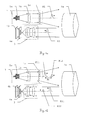
- Fig.1a is arranged in the transmitter unit 1 Pulse laser diode 1a as a transmitter diode with pulse modulation electromagnetic Radiation with pulses P1 generated as a signal.
- a suitable pulse duration is 50, for example Nanoseconds.
- the strong signals generated by this with optical performance in the watt range are robust against Ambient light reflections. Even sunlit reflecting surfaces are therefore weaker than the received signal pulse.
- the radiation generated is oriented in a vertically Fan emitted, the device side by a combination from a lens 1b and a cylindrical lens array 1c is produced.
- a lens 1b and a cylindrical lens array 1c is produced.
- Components are used, e.g. Microlens arrays or diffractive optical elements.
- the fan-like field of view becomes the receiver side through a slit diaphragm 4a in front of a receiving diode photosensitive element 4b together with a lens 3 realized with a cylindrical effect.
- FIG. 1b In the second implementation form shown in FIG. 1b are the same on the device side in the transmission unit 1 Components of pulse laser diode 1a, lens 1b and cylindrical lens array 1c used.
- the pulse rate is in the kHz range.
- the emitted radiation now has a pulse P11 with a larger one and a pulse P12 with a lower maximum pulse height, which follow one another in time and thus in this form of realization represent a double pulse.
- the reflected pulses P21 and P22 detected by the receiving unit. This exists again from a lens 3 with a cylindrical effect and a slit diaphragm 4a in front of a receiving diode as photosensitive Element 4b.
- the one in the reception dynamic range of the recipient When receiving the impulses of different intensity evaluated the one in the reception dynamic range of the recipient.
- This example is for a shorter one Measuring distance, the limit of which is, for example, 20 m can, the reflected pulse P22 with low pulse height and for a larger measuring distance the reflected pulse P21 used with a larger pulse height.
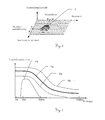
- FIG 2 is a section of a two-dimensional schematic Intensity image shown with target object.
- the individual signal pulses 5 detected by the receiver depending on the time of their issue with time resolved sampling detected. With every laser pulse Another signal track is created along the intensity image the distance axis. With the time-resolved sampling there is an assignment with regard to the distance, and the Emission times determine the horizontal angle belonging to the signal track firmly.
- the signal-distance model forms the basis of the plausibility check and the object width-distance model (tolerance value tables).
- the object width or extent is based on the product of pulse number and angular velocity calculated. There is also a consideration or calculation of the reflectance of the target object possible.
- the extent of the object is an important identifier, since traffic signs consistently compared to the actual ones Target marks, have large reflective surface.
- object-specific characteristics there can be one for each target type own, specific tolerance value table. there can also freely select a tolerance table for special, user-specific target types are used.
- Alternative or additional plausibility checks can also be carried out based on other criteria. For example can be spectrally different if necessary Reflectivity of different objects analyzed become.
- FIG. 3 shows an example of a plausibility check regarding the signal amplitude using a Plausibility band (tolerance value table).
- the plausibility check is done by checking whether a measured Value of a target within a plausibility band lies, which by a lower tolerance limit 8a and an upper tolerance limit 8b is defined.
- the theoretical The curve of all values of a target is determined by the distance Profile 7a shown. For example would like a value for a foreign target on its profile for example the profile 6a of a traffic sign, and thus outside of the plausibility band and thus as Foreign target can be identified.
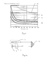
- FIG.4 Another plausibility check procedure regarding the apparent object size, again using a plausibility band (tolerance value table) shown in Fig.4.
- a tolerance value table is shown, which is the apparent object width in units of time with logarithmic scale for a horizontal scan of the Includes measuring device for the different distances, in which a target can be found.
- Also here is a check whether the measured value is within by the lower tolerance limit 8c and the upper tolerance limit 8d defined plausibility band. On Value for a foreign target would be on or in the Close to its theoretical profile 6b and thus outside of the plausibility band.
- 5a-b show the conditions in the reflection of the emitted pulses on a retroreflector compared to Reflection on a foreign target for the close range.
- Fig.5a the reflection on a retroreflector is shown schematically 2a shown in the vicinity.
- the Radiation emitted by the transmitter unit 1 is emitted by the retroreflector 2a reflected parallel offset and can thus in the axis defined by lens 3 and detector 4 of the receiving unit.
- Fig. 5b The deviating situation with the reflection on one Foreign target 2b is shown in Fig. 5b.
- the foreign goal does not lead to a parallel offset from that of the transmission unit 1 emitted radiation, so this is not in the through Objective 3 and detector 4 defined axis recorded can be.
- a biaxial arrangement of the visual fields of Sending unit 1 and receiving unit thus enable suppression an acquisition of external targets for the close range.
- the fan-shaped Field of vision can be divided into several sectors alternatively, several subjects can be placed side by side be used.
- the Figures 6a-c show accordingly alternative embodiments of an inventive Receiver unit with structured compartments, horizontal Tuft of fans and two-dimensional structured field of vision.
- the sensor fan is on the receiving side divided into segments. This creates a rough spatial Position determination also possible in the direction of the subject.
- FIG. 6a shows the structuring of the fan of the receiving unit.
- the one emitted by the transmitter unit 1 and one Retroreflector 2a reflected radiation is now transmitted through a division of the receiving fan with additional location information receive.
- This division of the fan 9a can be divided into several sectors by a slit diaphragm 11a in the first focal point of the cylindrical receiver optics.
- a switchable slot cover can be used for optionally the transmission of the relevant slot can be changed.
- the photosensitive element 12a is placed in the area of the second focal plane to the visual field the receiving optics 10 perpendicular in the spatial direction to cover fan with high transmission.
- the slit aperture 11a becomes the receiving fan in, for example 3 sectors divided, which is a rough position measurement also in the vertical direction.
- the one from the retroreflector 2a coming radiation happens in the shown Example the middle opening of the slit diaphragm 11a, see above that a rough estimate of the angular range in vertical Direction can take place.
- FIG. 6b shows several compartments.
- the production several receiving compartments arranged side by side as a fan cluster 9b is carried out by using a structured photosensitive receiving surface 12b in the second focal plane, especially in connection with a slot diaphragm 11b structured in the same arrangement.
- This division of the photosensitive receiving surface 12b e.g. in a linear array of photodetectors the clump of search subjects lying side by side.
- another number of subjects can be selected by choosing a suitable subdivision cause.
- tufts are also included two or four compartments possible.
- the middle fan of this example which is parallel to the transmission axis, reacts to the retroreflector 2a, which is towards the transmission axis inclined fan reacts to objects with single mirroring, the third subject only on sun reflections.
- a structured one photosensitive receiving surface 12b therefore increases the Security regarding correct identification reflective Objects.
- a receiving unit according to the invention with two-dimensional Structuring of the visual field is shown in Fig.6c.
- the receiving optics 10 with radiation detected in their visual field is transmitted via a Beam splitter 13 directed to two different detectors.
- the first detector consists of a vertically structured one photosensitive receiving surface 12b and a corresponding Slit aperture 11b in the second focal plane.
- the second detector consists of a horizontally structured one photosensitive receiving surface 12c with associated Slit aperture 11c in the first focal plane.
- photosensitive elements 12a or Receiving surfaces 12b and 12c can be of any suitable shape of location-sensitive detectors such as Receiving diodes or Receive diode arrays or PSD can be used.
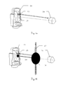
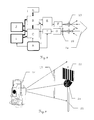
- Fig. 7a-b the combination of an inventive Device 15 with an AZE system 16 together with the schematic sequence of the method is shown.
- FIG. 7 a shows the structural integration of an inventive one Device 15 and an AZE system into a geodetic Measuring device 14. This complements the inventive Device 15 as, for example, in a theodolite geodesic measuring device 14 already existing AZE system 16.
- the emission to recognize a retroreflector 2a as Target mark by the device 15 and AZE system according to the invention 16 takes place in this example essentially in parallel to each other.
- FIG. 7b shows the combination of the two searches shown schematically.
- the device according to the invention 15 there is a quick environmental scan with a vertical one Compartments 17 for determining the horizontal angle one Target.
- a Retroreflector 2a found as target and its location roughly determined.
- the measurement data of the device according to the invention 15 can be used to support other sensors be forwarded in the geodetic measuring device 14, for example to an AZE system 16.
- This AZE system 16 searches for the retroreflector with his fan 18 2a and thus also determines the vertical angle.
- There is a channel separation to other optical sensors by means of suitable optical carrier wavelengths, a simultaneous use of several sensors in the geodetic measuring device or several geodetic measuring devices.
- a system clock A serves as a common time base, with the image memory I, the electronic evaluation unit C, the control and signal processing unit B, the Analog-to-digital converter H and the laser driver and controller E is connected.
- the laser F emits radiation that via a beam-shaping optics 19 onto a retroreflector is sent. After the reflection has taken place, it becomes Receive radiation and via an image-forming mask 20 the detector G directed.
- the signal of this detector G is converted by the analog-to-digital converter H and in the electronic Processing unit C further processed.
- This is connected to the control and signal processing unit B, the image memory I and the tolerance value tables J for all possible target types. Via an interface there is the possibility of a connection to one other system D, e.g. a geodetic measuring device or the evaluation unit of a turning device.
- FIG. 9 shows a geodetic surveying system according to the invention with automatic target recognition based on of a barcode pattern on the target mark.
- the target marking which are exemplarily designed as a retroreflector 2a is additionally attached a coded target plate 22.
- the coding consists of optically highly reflective Stripes, which are scanned sequentially during a search become.
- the vertical compartments 17 make one sufficient large vertical angle swept over so that parallel illumination or detection of target plate 22 and retroreflector 2a is possible.
- the one received by the search sensor The signal is amplitude modulated in time, the code the target plate is transformed into a chronological sequence. The result is a very quick target search and identification of the target mark possible.
- By means of a Coordinate database certain target marks, but also hide disruptive objects. Such points are not approached.
- the data image is next to the object distance and object size also the coded information of the target plate.
Abstract
Description
Die Erfindung betrifft ein Verfahren zum automatischen Auffinden
einer Zielmarke nach dem Oberbegriff des Anspruchs
1, eine Vorrichtung nach dem Oberbegriff des Anspruchs 11,
eine Empfangseinheit nach dem Oberbegriff des Anspruchs 19,
ein geodätisches Messgerät nach dem Oberbegriff des Anspruchs
23 und geodätische Vermessungssysteme nach Anspruch
25 oder 26.The invention relates to a method for automatic detection
a target according to the preamble of the
Seit langem besteht in Zusammenhang mit geodätischen Vermessungen das Bedürfnis, im Gelände befindliche und zu vermessende geodätische Zielmarken automatisch zu erkennen und möglichst auch gleichzeitig grob zu vermessen. Diese Notwendigkeit wird durch die Tendenz zu vollautomatischen und integrierten Vermessungssystemen noch verstärkt.Has existed in connection with geodetic surveys for a long time the need to be in the field and to be measured automatically recognize geodetic targets and if possible also roughly measured at the same time. That need is due to the tendency towards fully automatic and integrated surveying systems.
Optoelektronische Vorrichtungen zur automatischen Auffindung und Lokalisierung von geodätischen Zielmarken, beispielsweise eines Retroreflektors oder einer Reflexfolie, werden dementsprechend bereits in verschiedenen Ausgestaltungsformen verwendet. Vorrichtungen dieses Typs ergänzen dabei die bei geodätischen Vermessungsaufgaben gebräuchlichen sensorischen Messmittel, insbesondere erbringt die Kombination mit einem motorisierten Theodoliten mit automatischer Zielerfassung erhebliche Vorteile.Optoelectronic devices for automatic detection and localization of geodetic targets, for example a retroreflector or a reflective tape, are accordingly already in various forms used. Complement devices of this type thereby the ones used for geodetic surveying tasks sensory measuring equipment, in particular provides the Combination with a motorized theodolite with automatic Target acquisition has significant advantages.
Vorrichtungen zum Auffinden von Zielmarken und damit auch die Erfindung betreffen dabei im weiteren Sinn alle Messgeräte, die durch direkt vom Menschen zu handhabende Richtmittel auf Messpunkte optisch ausgerichtet werden. Unter dem Begriff "geodätisches Messgerät" soll in diesem Zusammenhang verallgemeinernd stets ein Messinstrument verstanden werden, das über Vorrichtungen zur Messung oder Überprüfung von Daten mit räumlichem Bezug verfügt oder auch zur Ausrichtung dient. Insbesondere betrifft dies die Messung von Entfernung und/oder Richtung bzw. den Winkeln zu einem Bezugs- oder Messpunkt. Darüber hinaus können jedoch noch weitere Vorrichtungen, z.B. Komponenten zur satellitengestützten Ortsbestimmung (bspw. GPS oder GLONASS), vorhanden sein, die für erfindungsgemässe Messungen verwendet werden können. Insbesondere sollen hier unter einem geodätischen Messgerät Theodoliten, Nivelliere oder auch sogenannte Totalstationen als Tachymeter mit elektronischer Winkelmessung und elektrooptischem Entfernungsmesser verstanden werden. Gleichermassen ist die Erfindung zur Verwendung in spezialisierten Vorrichtungen mit ähnlicher Funktionalität geeignet, z.B. in militärischen Richtkreisen oder in der industriellen Bauwerks- oder Prozessüberwachung, diese Systeme werden hiermit ebenfalls unter dem Begriff "geodätisches Messgerät" erfasst.Devices for finding target marks and thus also the invention relates in a broader sense to all measuring devices, the directives to be handled directly by humans be optically aligned to measuring points. Under the term "geodetic measuring device" is intended in this context generally understood a measuring instrument be that about devices for measurement or verification of data with spatial reference or also serves for alignment. This particularly concerns the measurement from distance and / or direction or the angles to a reference or measurement point. Beyond that, however still other devices, e.g. Components for satellite-based Location determination (e.g. GPS or GLONASS), available be used for measurements according to the invention can be. In particular, here under a geodetic Measuring device theodolites, levels or so-called Total stations as tachymeters with electronic Angle measurement and electro-optical rangefinder understood become. The invention is equally applicable in specialized devices with similar Functionality suitable, e.g. in military circles or in industrial building or process monitoring, these systems are hereby also under the The term "geodetic measuring device" recorded.
Die heute gebräuchlichen, automatisierten Theodoliten, als ein Beispiel für ein geodätisches Messgerät, sind nicht nur mit Winkel- und Distanzsensoren sondern auch mit einer optoelektronischen Zielsuch-, Positionierungs- und Zielpunktvermessungsvorrichtung, im folgenden Automatische Zielerfassungseinheit (AZE) genannt, bestückt. Solche Theodolite sind in der Lage, den Zielpunkt automatisch anzufahren und die Raumkoordinaten zu vermessen. Im Fall einwandfreier Funktion ist die Zeitersparnis mit solchen automatisierten Instrumenten erheblich. Ist das System zudem über Fernbedienung, beispielsweise vom Zielpunkt aus als Ein-Mann-Station bedienbar, so ist die Arbeitsleistung und die damit erzielte Kostenersparnis noch ausgeprägter. The automated theodolites in use today, as an example of a geodetic measuring device are not only with angle and distance sensors but also with an optoelectronic Target search, positioning and target point measuring device, in the following automatic target acquisition unit Called (AZE). Such theodolites are able to automatically move to the destination and to measure the spatial coordinates. In the case of impeccable Function is the time saving with such automated Instruments considerably. If the system is also via remote control, for example, from the target point as a one-man station operable, so is the work done and with it achieved cost savings even more pronounced.
Ein wesentlicher Bestandteil dieser automatisierten Vermessungs-Instrumente ist die AZE. Bekannt sind diverse Lösungen wie CCD- oder CMOS-Kameras mit Bildverarbeitung, optoelektronische positionssensitive Halbleiterdetektoren (PSD), 4 Quadranten-Dioden, akustooptische Strahlscanner usw.An integral part of these automated surveying instruments is the AZE. Various solutions are known such as CCD or CMOS cameras with image processing, optoelectronic position sensitive semiconductor detectors (PSD), 4 quadrant diodes, acousto-optical beam scanners etc.
Zur Hauptfunktion dieser AZE gehört die exakte Vermessung einer Zielmarke oder eines Reflektors mit mm-Genauigkeit bei kurzen und langen Distanzen, wobei Distanzen über 1000m ebenfalls vermessen werden können. Um diese mm-Genauigkeit zu erreichen, haben diese Suchvorrichtungen durchwegs den Nachteil eines eingeschränkten Sensor-Gesichtsfelds. Nur bei kleinen bis mittleren Gesichtsfeldern von wenigen Grad lassen sich Punktgenauigkeiten von <5mm bei 1000m erreichen.Precise measurement is one of the main functions of this AZE a target or a reflector with mm accuracy for short and long distances, with distances over 1000m can also be measured. To this mm accuracy to achieve, these search devices consistently have the Disadvantage of a restricted sensor field of view. Just with small to medium visual fields of a few degrees point accuracies of <5mm at 1000m can be achieved.
Ein wesentlicher Nachteil eines kleinen Sensor-Gesichtsfelds ist die erschwerte Zielsuche, da sich die zu vermessende Zielmarke zu Beginn einer Messung oft ausserhalb des Gesichtsfelds befindet. Bei vielen Anwendungen, insbesondere im Kurzdistanzbereich, mit welchem ein weitwinkliges Arbeitsfeld einhergeht, besitzt ein ausgedehntes Sensor-Gesichtsfeld Vorteile.A major disadvantage of a small sensor field of view is the difficult goal search, because the measuring target at the beginning of a measurement often outside of the visual field. In many applications, especially in the short-distance range, with which a wide-angle The field of work involved has an extensive scope Sensor field of view advantages.
Heute kommen bei der Zielsuche grundsätzlich 2 Methoden zum Einsatz. Bei der einen Methode sucht der Sensor nach einem programmierten Algorithmus oder Verfahren das Ziel selbständig, dies braucht aber Zeit wegen des kleinen Gesichtsfelds, bei der zweiten Methode wird das Suchfeld durch den Benutzer definiert, sodass die Zielobjektsuche gerichteter und mit geringerem Zeitaufwand abläuft, dies hat aber den Nachteil, dass die Suchfeldkonfiguration bei jedem Standortwechsel neu programmiert werden muss.Today there are basically two methods for finding a target Commitment. In one method, the sensor searches for one programmed algorithm or procedure the target independently, but this takes time because of the small field of vision, in the second method, the search field is replaced by the User defined so that the target object search is more targeted and takes less time, but this has the Disadvantage that the search field configuration with every change of location must be reprogrammed.
Ein weiterer Nachteil existiert bei der Verfolgung von bewegten Zielobjekten. Bei zu raschen oder ruckartigen tangentialen Bewegungen zur Zielrichtung des automatisierten Theodolits kann es vorkommen, dass die Zielmarke aus dem Gesichtsfeld der Zieldetektionsvorrichtung herausfährt. Ein auch nur kurzzeitiger Zielverlust kann dabei den effizienten Verfolgungsprozess stören.Another disadvantage exists when tracking moving Targets. If the tangential is too rapid or jerky Movements to the goal of the automated Theodolites can happen that the target mark from the Field of vision of the target detection device extends. On even a brief loss of target can make the efficient Disrupt the persecution process.
Weitere Mängel bei Vorrichtungen mit AZE des Stands der Technik sind darüber hinaus die fehlende Robustheit bei (Eigen-)Reflexen an Fremdzielen und eine fehlende bzw. nicht hinreichend sichere Zielerkennung. Fremdziele sind solche mit hohem Reflexionsgrad, wie z.B. Verkehrstafeln. Bei der Zielerkennung ist die Identifikation der zu vermessenden Zielmarke bisher nicht zufriedenstellend gelöst, da insbesondere die fehlende Robustheit bei Sonnenreflexen an Gegenständen mit glänzender Oberfläche nachteilig wirkt.Other shortcomings in devices with AZE of the prior art Technology are also the lack of robustness (Self-) reflexes to external goals and a missing or insufficiently secure target recognition. Are foreign goals those with high reflectance, e.g. Traffic signs. In the case of target recognition, the identification of those to be measured is required Target has not yet been satisfactorily resolved because in particular the lack of robustness in sun reflections Objects with a shiny surface adversely affect.
Zwar können Sonnenreflexe an Gegenständen mit modernen Vorrichtungen erkannt werden, jedoch braucht die hierfür notwendige Analyse Zeit, wodurch der Suchprozess bei jedem Reflex abgebremst wird.Sun reflections on objects with modern devices can be recognized, but needs the necessary for this Analysis time, making the search process with every reflex is braked.
Bei Grobsuchsensoren des Stands der Technik entsteht aufgrund des kleinen Sensor-Gesichtsfelds ein zu grosser Zeitbedarf bei der Grobzielsuche. Das kleine Gesichtsfeld wirkt sich dabei überproportional aus, erstens besitzt dieses einen kleineren Abdeckungsbereich der Umgebung, so dass das Abfahren des Suchbereichs einen längeren Zeitraum erfordert. Zweitens muss das Abfahren mit einer geringeren Scan-Geschwindigkeit wegen kurzer Verweildauer des Objekts im Gesichtsfeld erfolgen. Eine fächerartige Gestaltung des Erfassungsbereichs der Sensoren ist diesbezüglich bereits besser geeignet, jedoch sind die Gesichtsfelder, gebildet durch Fächerwinkel von typischerweise 1 bis 5 Grad, nach wie vor viel zu klein.In coarse search sensors of the prior art arises due to the small sensor field of view takes too much time in the rough target search. The small field of vision works disproportionately, firstly, it has one smaller coverage area of the area, so that Moving the search area requires a longer period of time. Second, the shutdown must be done at a lower scan speed because of the short dwell time of the object in the Field of view. A fan-like design of the detection area the sensors are already in this regard more suitable, but the visual fields are formed by fan angles of typically 1 to 5 degrees much too small as before.
Aus der Patentschrift CH 676 042 ist eine Vorrichtung mit fächerartigem Sender und Empfänger bekannt, welche in einem drehbaren Messkopf untergebracht ist. Von der Sendeeinheit werden Lichtimpulse in einem Lichtfächer ausgesendet, die reflektierten Impulse werden hinsichtlich Winkelinformation entsprechend ausgewertet. Diese Vorrichtung hat jedoch den erheblichen Nachteil, nicht nur die zu vermessenden Zielobjekte sondern auch fremde, störende Objekte anzufahren. Solche Objekte sind unter anderem optisch reflektierende Gegenstände, wie Schaufenster oder Verkehrstafeln, aber auch gespiegeltes Sonnenlicht an Motorfahrzeugen.From the patent specification CH 676 042 is a device with fan-like transmitter and receiver known, which in one rotatable measuring head is housed. From the sending unit light pulses are emitted in a light fan, which reflected pulses are regarding angle information evaluated accordingly. However, this device has the considerable disadvantage, not only the target objects to be measured but also to approach foreign, disturbing objects. Such objects are, among other things, optically reflective Objects, like shop windows or traffic signs, however also reflected sunlight on motor vehicles.
Eine Weiterführung der obigen Zielsuchvorrichtung zur groben Bestimmung der Zielkoordinaten ist in CH676041 beschrieben. Dabei erfolgt eine Kombination mit einer optoelektronischen Vorrichtung zur Feinmessung. Die eigentliche Zielsuchvorrichtung spannt zwei senkrecht aufeinander stehende Fächer auf, mit denen die Lage des Zielpunktes zweidimensional grob vermessen wird, die anschliessende Feinvermessung mit der zweiten Vorrichtung kann dann ohne Zielsuchvorgang durchgeführt werden. Der Nachteil dieser Kombination ist ebenfalls die fehlende Robustheit bezüglich eines fehlerhaften Einlockens auf Fremdobjekte.A continuation of the above target search device for the rough Determination of the target coordinates is described in CH676041. It is combined with an optoelectronic Device for fine measurement. The real one Target search device spans two perpendicular to each other Subjects with which the location of the target point is two-dimensional is roughly measured, the subsequent fine measurement the second device can then be used without a destination search be performed. The disadvantage of this combination is also the lack of robustness in relation to one incorrect enticing to foreign objects.
Eine weitere Vorrichtung ist aus der Schrift US 6,046,800 bekannt. Geoffenbart wird ein motorisierter Theodolit, der mit einem Sensor zur Erfassung der Zielpunktkoordinaten bestückt ist, bestehend aus einem oder zwei fächerartigen Sendebündeln und zwei optischen Empfangskanälen. Eine Besonderheit dieser Vorrichtung besteht darin, dass die optischen Achsen des Sendekanals und der beiden Empfänger triaxial in einer Ebene liegen, dies ermöglicht bei einer Schwenk- oder Suchbewegung des Theodolits die Unterscheidung von normal reflektierenden und retroreflektierenden Objekten durch Auswertung der zeitlichen Abfolge der beiden Empfangssignale. Diese Methode der empfängerseitigen Pupillenteilung hat aber den Nachteil, dass dieses Unterscheidungsmerkmal nur bei kurzen Distanzen existiert, zudem ist die Vorrichtung wegen den beiden Empfangskanälen aufwendig bzw. teuer.Another device is from US Pat. No. 6,046,800 known. A motorized theodolite, the equipped with a sensor for detecting the target point coordinates is composed of one or two fan-like Transmission bundles and two optical reception channels. A special feature this device is that the optical Triaxial axes of the transmission channel and the two receivers lie in one plane, this enables one Panning or searching movement of the theodolite makes the distinction of normal reflective and retroreflective Objects by evaluating the chronological order of the two Receive signals. This method of pupil division on the receiver side has the disadvantage, however, that this distinguishing feature only exists at short distances, moreover is the device is expensive because of the two reception channels or expensive.
Aus der Schrift DE 196 23 060 ist ebenfalls ein geodätisches Gerät zur Grobzielsuche bekannt. Diese Vorrichtung besteht aus einem optoelektronischen, im wesentlichen als Scanner ausgebildeten Vertikalwinkelsucher. Sende- und Empfangsstrahl werden dabei um eine (zweite) horizontal liegende motorisch angetriebene Achse rotiert. Beabsichtigt wird eine grosse Reichweite, die aufgrund der parallel kollimierten optischen Bündel erreicht wird, diese Eigenschaft wird jedoch mit dem Nachteil der punktartigen und damit sequentiellen und zeitaufwendigen Raumabtastung erkauft. Beim Suchvorgang wird der rasch vertikal rotierende Sensorstrahl gleichzeitig langsam in horizontaler Richtung bewegt. Ein weiterer Nachteil ist der Bedarf eines zusätzlichen Winkelmesssystems an der Scannerachse zur Grobbestimmung des Vertikalwinkels. Würde der Raum hingegen mit einem fächerartigen optischen Messbündel abgesucht, so wäre lediglich eine eindimensionale Drehbewegung um eine Achse notwenig. From the document DE 196 23 060 is also a geodetic Coarse target search device known. This device consists of an optoelectronic, essentially as Scanner trained vertical angle finder. Send and receive beam become a (second) horizontal motor-driven axis rotates. Intended becomes a long range, due to the collimated in parallel optical bundle is achieved this property However, with the disadvantage of point-like and thus sequential and time-consuming room scanning. At the Searching is the rapidly vertically rotating sensor beam moved slowly in the horizontal direction at the same time. On Another disadvantage is the need for an additional angle measuring system on the scanner axis for rough determination of the vertical angle. Would the room, however, with a fan-like optical measuring bundle searched, so only one would be one-dimensional rotation around an axis is necessary.
Ein wesentlicher Nachteil aller bisher bekannten Vorrichtungen ist die ungenügende Robustheit gegen stark reflektierende Fremdobjekte, die versehentlich als Zielobjekt interpretiert werden, wie auch Störung oder zumindest Verzögerung des Suchvorgangs durch starkes Sonnenlicht oder Sonnereflexe.A major disadvantage of all previously known devices is insufficient robustness against highly reflective Foreign objects that are mistakenly interpreted as the target object as well as disruption or at least delay the search process due to strong sunlight or sun reflections.
In den meisten Fällen wird der Suchvorgang manuell über Sprechfunk oder Datenfunk unterstützt. Bei der im Dokument DE 197 334 91 beschriebenen Vorrichtung wird mittels einer zusätzlichen am Zielobjekt angebrachten optischen Empfangseinheit geprüft, ob der Suchstrahl des Theodoliten das Zielobjekt trifft. Wird ein entsprechendes Suchsignal empfangen, so meldet das Zielobjekt über Datenfunk seine Identifikation an den Theodoliten. Diese Lösung ist zwar robust, beeinträchtigt aber die Ergonomie am Zielobjekt.In most cases, the search process is done manually Radiotelephony or data radio supported. At the in the document DE 197 334 91 device is described by means of a additional optical receiver unit attached to the target object checked whether the theodolite's search beam Target object hits. If a corresponding search signal is received, the target object reports its identification via radio data transmission on the theodolites. While this solution is robust, but affects the ergonomics of the target object.
Die Aufgaben der vorliegenden Erfindung bestehen in einer Verbesserung der eingangs definierten Sensoreinrichtungen.The objects of the present invention are Improvement of the sensor devices defined at the beginning.
Dabei besteht eine Aufgabe darin, ein geodätisches Messgerät zur Grobzielsuche bereitzustellen, das in Hinblick auf eine möglichst schnelle Lokalisierung und Identifikation von Zielobjekten und deren Ermittlung der Grobkoordinaten geeignet ist und das eine verkürzte Suchzeit bei einer Reichweite von bis zu 1000m besitzt. Die Geschwindigkeit der Zielsuche stellt ein Hauptproblem dar, da diese nach einem grossen Sensorgesichtsfeld verlangt, das durch einen entsprechend grossen Fächerwinkel erreicht wird. Mit grösser werdendem Fächerwinkel nimmt jedoch die Reichweite ab. Es ist daher die Aufgabe der Erfindung den Reichweitenbereich von geodätischen Applikationen und gleichzeitig eine hohe Suchgeschwindigkeit zu erreichen. One task is a geodetic measuring device to provide rough target search that with regard to the fastest possible localization and identification of target objects and their determination of the rough coordinates is suitable and that a shorter search time for a Has a range of up to 1000m. The speed The search for a target is a main problem since requires a large sensor field of view, correspondingly large fan angle is reached. With bigger however, the fan angle decreases the range. It is therefore the object of the invention to cover the range of geodetic applications and at the same time one to achieve high search speed.
Eine weitere Aufgabe besteht in Ermöglichung eines Suchvorgangs, der gegenüber Fremdlicht und Eigenreflexe an Fremdzielen robust ist. Der Suchvorgang darf dabei nicht durch Fremdziele mit hohem Reflexionsgrad oder durch Gegenstände mit Sonnenreflex zeitlich verzögert oder unterbrochen werden. Dabei umfasst die Aufgabe die simultane Identifikation der zu vermessenden Zielobjekte anhand geeigneter Identifikations-Merkmale auch während des Suchlaufs.Another task is to enable a search process compared to extraneous light and self-reflexes at external targets is robust. The search process must not go through Foreign targets with a high degree of reflection or through objects be delayed or interrupted with solar reflex. The task involves simultaneous identification of the target objects to be measured using suitable identification features even during the search.
Diese Aufgaben werden erfindungsgemäss durch die kennzeichnenden
Merkmale der Ansprüche 1 bzw. 11 sowie durch die kennzeichnenden
Merkmale der Unteransprüche gelöst. Eine Empfangseinheit,
ein geodätisches Messgerät und geodätische
Vermessungssysteme ergeben sich aus den Ansprüchen 19, 23,
25, 26 bzw. 27.According to the invention, these tasks are performed by the characterizing
Features of
Die vorliegende Erfindung betrifft im wesentlichen eine optoelektronische Zielsuchvorrichtung bestehend aus einem fächerartigen Sendekanal, welcher das zu lokalisierende Ziel bestrahlt, einem fächerartigen Empfangskanal, welcher das vom Zielobjekt reflektierte Licht empfängt, einem motorisierten Messgerät, beispielsweise einem Theodoliten, welches sich um eine der beiden Achsen während dem Suchlauf bewegt, mindestens einer elektronischen Auswerteeinheit zur Bestimmung der groben Zielpunktlage, Signalstärke des reflektierten Signals, der Ausdehnung des Zielobjekts in Scanrichtung, und der Distanz zum Zielobjekt. Optional kann auch die Dauer des reflektierten optischen Signals erfasst werden.The present invention relates essentially to an optoelectronic Target search device consisting of a fan-like Send channel, which is the target to be located irradiated, a fan-like receiving channel, which the receives light reflected from the target object, a motorized one Measuring device, for example a theodolite, which around one of the two axes during the search moved, at least one electronic evaluation unit Determination of the rough target point position, signal strength of the reflected Signal, the extent of the target in Scan direction, and the distance to the target object. Optionally can also recorded the duration of the reflected optical signal become.
Sowohl die Ebenen der beiden optoelektronischen Lichtfächer als auch die Drehachse des Theodolits (=Scanachse für den Suchlauf) sind parallel zueinander orientiert. Im folgenden sollen die Begriffe der horizontalen und vertikalen Bewegung so verstanden werden, dass bei einer Bewegung stets eine entsprechende Komponente und eine dementsprechende Bewegung vorhanden sind. Eine horizontale Bewegung der Sendeeinheit kann somit insbesondere auch durch eine gegenüber dem Horizont geneigte Bewegung erreicht werden.Both the levels of the two optoelectronic light fans as well as the axis of rotation of the theodolite (= scan axis for the Search) are oriented parallel to each other. Hereinafter are supposed to be the terms of horizontal and vertical movement to be understood in such a way that with a movement always a corresponding component and a corresponding movement available. A horizontal movement of the transmitter unit can therefore also in particular by one movement inclined to the horizon can be achieved.
Ein leistungsstarker und sensorisch empfindlicher Laufzeitmesser dient als Zielsuchvorrichtung. Geeignete Laufzeitmesser mit Impulsmodulation haben grosse Reichweite und kurze Messzeit. Die erreichbaren optischen Sendeleistungen mit den lediglich nur Millimeter grossen Pulslaserdioden liegen dabei über 100 Watt. Dadurch lassen sich auch bei fächerartiger Aufweitung des Sendestrahls die geforderten Reichweiten für geodätische Applikationen realisieren. Während eines Suchlaufs wird der Laufzeitmesser im Dauermessmodus betrieben. Dabei emittiert der Sender optische Impulse mit einer Rate im kHz-Bereich. Da die Vorrichtung im Einzelschussauswerteverfahren betrieben wird, sind Informationen über die gescannte Umgebung im Nanosekunden- bis Mikrosekundenbereich vorhanden. Die empfangenen Impulse werden mit einem schnellen AD-Wandler abgetastet, wodurch ein Intensitätsbild der Umgebung entsteht. Dabei können die abgetasteten Impulse beispielsweise in einem 2D-Speicher abgelegt und nachfolgend ausgewertet werden oder aber es erfolgt zeitnah eine erste Analyse und die weitere Auswertung basiert auf diesen ersten Ergebnissen, die z.B. eine Anhäufung oder ein Zusammenzug der Impulse sein können.A powerful and sensory sensitive transit time meter serves as a destination search device. Suitable time meter with pulse modulation have a long range and short measuring time. The achievable optical transmission powers with the pulse laser diodes, which are only millimeters in size are over 100 watts. This also allows fan-like expansion of the transmission beam the required Realize ranges for geodetic applications. While of a search runtime meter in continuous measurement mode operated. The transmitter emits optical pulses at a rate in the kHz range. Since the device in Single shot evaluation process is information over the scanned environment in the nanosecond to Microsecond range available. The received impulses are scanned with a fast AD converter, thereby an intensity picture of the surroundings is created. The sampled pulses, for example in a 2D memory filed and subsequently evaluated or it an initial analysis and further evaluation are carried out promptly is based on these first results, e.g. a Accumulation or contraction of the impulses can be.
Die Dimensionierung des optischen Sende-Fächers ist so bemessen, dass dieser die typischerweise zu vermessende Umgebung in vertikaler Richtung abdeckt. Die Divergenz in senkrechter Richtung zum Fächer ist vorzugsweise beugungsbegrenzt schmal.The dimensioning of the optical transmission fan is dimensioned in such a way that this is the typical environment to be measured covers in the vertical direction. The divergence in vertical Diffraction direction is preferably limited narrow.
Eine Suche mit einer erfindungsgemässen Vorrichtung liefert als Output ein Intensitätsbild der abgesuchten Umgebung. Die Auswertung des 2-dimensionalen Intensitätsbildes kann entweder nach erfolgtem Scan oder aber auch simultan bzw. zeitnah während der Aufnahme erfolgen. Mögliche Ergebnisse einer solchen Auswertung können beispielsweise
- Intensitätsmaxima allfälliger Zielobjekte,
- ein Zeitpunkt der Zielfindung oder äquivalent auch Winkel zum Zielobjekt oder die
- Distanz zum Zielobjekt sein.
- Intensity maxima of any target objects,
- a point in time to find the target or equivalent also angle to the target object or the
- Distance to the target object.
Die Robustheit gegenüber sonnenreflektierenden Oberflächen und spiegelnden Fremdzielen wird erfindungsgemäss verbessert bzw. erst erreicht. Wegen der starken Laserimpulse sind sonnenreflektierende Oberflächen im 2-dimensionalen Intensitätsbild aus zwei Gründen nicht sichtbar. Erstens ist die Laserstrahlung des Senders spektral schmal und gestattet ein vergleichbar schmales Interferenzfilter im Empfangsstrahlengang, das Sonnenlicht wird weitgehend abgeblockt. Zweitens erzeugen die Impulslaser starke Lichtblitze, deren Strahldichte grösser ist als diejenige von Sonnenreflexen. Eine Robustheit gegenüber sonnenreflektierenden Oberflächen wird hierdurch erreicht.The robustness against sun reflecting surfaces and reflecting foreign goals is improved according to the invention or only reached. Because of the strong laser pulses are sun reflecting surfaces in 2-dimensional Intensity image not visible for two reasons. First the laser radiation from the transmitter is spectrally narrow and permitted a comparatively narrow interference filter in the receive beam path, sunlight is largely blocked. Second, the pulse lasers generate strong flashes of light, whose radiance is greater than that of solar reflections. A robustness against sun reflecting This achieves surfaces.
Die erforderliche Robustheit gegenüber Fremd- oder Störzielen ist schwieriger zu erreichen. Zunächst erscheinen im 2-dimensionalen Intensitätsbild neben dem eigentlichen, zu lokalisierenden Zielobjekt oft weitere optisch reflektierende Objekte. The required robustness against foreign or interference targets is more difficult to achieve. First appear in 2-dimensional Intensity picture next to the actual one, too localizing target object often more optically reflective Objects.
Im Nahbereich unter 10m kann das Problem durch eine besondere biaxiale Anordnung der beiden optischen Fächer gelöst werden. Sender und Empfänger liegen biaxial nebeneinander, wobei der seitliche Versatz senkrecht zu den Fächern gerichtet ist. Die Gesichtsfelder von Sender und Empfänger überlappen dadurch unter 10m nicht. Einfach-reflektierende Objekte, wie z.B. Spiegel, werden in diesem Distanzbereich vom Empfänger nicht gesehen, nur retroreflektierende Zielobjekte mit seitlichem Versatz des gespiegelten Strahls, wie beispielsweise die bei Vermessungsaufgaben gebräuchlichen Tripelprismen, erzeugen ein messbares Empfangssignal. Damit wird die Robustheit unter 10m durch Biaxialität gelöst.In the close range below 10m the problem can be caused by a special one Biaxial arrangement of the two optical compartments solved become. Transmitter and receiver are biaxially next to each other, the lateral offset is directed perpendicular to the compartments is. The fields of view of the sender and receiver therefore do not overlap below 10m. Easy-reflective Objects such as Mirrors are in this distance range not seen by the receiver, only retroreflective target objects with lateral offset of the mirrored beam, such as those commonly used in surveying tasks Triple prisms generate a measurable received signal. The robustness under 10m is solved by biaxiality.
Bei allen anderen Distanzen müssen die richtigen Zielobjekte aus den im 2-dimensionalen Intensitätsbild enthaltenen Objekten erfindungsgemäss identifiziert werden.For all other distances, the correct target objects must be from those contained in the 2-dimensional intensity image Objects are identified according to the invention.
Jeder Zieltyp erzeugt sowohl einen charakteristischen Signalverlauf als auch eine charakteristische Ausdehnung als Funktion der Distanz. Zielobjektidentifikation ist daher anhand der beiden distanzabhängigen Messkurven möglich. Bei der gemessenen jeweiligen Objektdistanz wird geprüft, ob Objektausdehnung und Signalstärke im Toleranzband des gesuchten Zielobjekts sind. Je nach konkreten Zielparametern und Messbedingungen genügt es unter Umständen, lediglich einen Vergleich bezüglich nur eines Grenzwertes durchzuführen, z.B. einen Vergleich gegenüber dem unteren Grenzwert bezüglich des Signals und gegenüber dem oberen Grenzwert bezüglich der Objektgrösse. Each target type generates a characteristic signal curve a characteristic extension as well Function of the distance. Target identification is therefore possible using the two distance-dependent measurement curves. at the measured respective object distance is checked whether Object extension and signal strength in the tolerance band of the sought Are the target. Depending on the specific target parameters and measurement conditions it may be sufficient, just carry out a comparison with only one limit value, e.g. a comparison against the lower limit regarding the signal and against the upper limit regarding the object size.
Wird nun während eines Scans ein reflektierendes Objekt angestrahlt, so werden laufend Signal und Objektausdehnung mit den geladenen Toleranzwerten verglichen. Sobald der Sendefächer ein allfälliges Objekt komplett überstrichen hat und alle Messwerte innerhalb der Toleranzwerte liegen, ist ein Zielobjekt identifiziert und gefunden. Je nach Anwendung wird an dieser Stelle der Suchprozess gestoppt oder es werden lediglich die Koordinaten, wahlweise auch Parameter wie Signal und Ausdehnung, gespeichert und der Suchprozess ohne Scanunterbrechung fortgesetzt, so dass weitere Zielobjekte gesucht und gefunden werden können.If a reflecting object is now illuminated during a scan, this way the signal and the object extension become constant compared with the loaded tolerance values. Once the Transmitter boxes completely painted over any object and all measured values are within the tolerance values, a target object is identified and found. Depending on the application the search process is stopped at this point or it only shows the coordinates, optionally also parameters like signal and extent, saved and the search process continued without interrupting the scan, leaving more Target objects can be searched and found.
Der durchaus mögliche Fall, dass bei gewissen Fächerstellungen mehrere Zielobjekte in unterschiedlicher Distanz gleichzeitig auftreten, ist aufgrund der Distanzmessung problemlos zu handhaben.The quite possible case that with certain subject positions several target objects at different distances occur simultaneously is due to the distance measurement easy to use.
In vielen Anwendungen wird unmittelbar nach der Instrumentenaufstellung als erstes die gesamte Umgebung abgescannt. Hierbei wird ein 2-dimensionales Intensitätsbild erzeugt, welches alle lichtstark reflektierenden Objekte enthält. Die Koordinaten der nicht relevanten Zielobjekte wie Störund Fremdziele werden berechnet und gespeichert. Mit der Kenntnis der Koordinaten aller Störobjekte und Fremdziele können diese von allen weiteren Suchläufen ausgeblendet werden. Damit lässt sich zusätzlich Suchzeit einsparen, da die für die Vermessungsaufgabe nichtrelevanten Objekte sensorisch nicht mehr existieren.In many applications, the instrument is installed immediately first scanned the entire area. This creates a 2-dimensional intensity image, which contains all highly reflective objects. The coordinates of the irrelevant target objects such as Störund Foreign goals are calculated and saved. With the Knowledge of the coordinates of all interfering objects and foreign targets can be hidden from all other searches become. This saves additional search time, because the objects that are not relevant for the measurement task are sensory no longer exist.
Ist ein Zielobjekt gefunden, so sind Distanz und eine Richtungskoordinate bekannt. Als nächstes wird die zweite Raumrichtung gemessen. Diese wird nach dem bekannten Suchverfahren mit der im Theodoliten vorhandenen automatisierten Zielerfassungseinheit (AZE) realisiert. Der AZE-Such- und Messvorgang ist in diesem Fall sehr effizient und schnell, da nur noch 1-dimensional bewegt bzw. gefahren werden muss. Die Kombination der beiden Vorrichtungen bewirkt einen zusätzlichen Nutzen. Da die AZE die Position des Zielobjekts auf Winkelsekunden genau misst, sind am Ende des AZE-Suchund Messprozess die Zielpunktkoordinaten nicht nur grob, sondern mit geodätischer Genauigkeit im mm-Bereich bis submm-Bereich bekannt.If a target object is found, then there is a distance and a direction coordinate known. Next is the second spatial direction measured. This is done according to the well-known search procedure with the automated in the theodolite Target acquisition unit (AZE) implemented. The AZE search and In this case the measuring process is very efficient and fast, since only one-dimensional movement or driving is required. The combination of the two devices creates an additional one Use. Because the AZE is the position of the target accurate to the second of an angle are at the end of the AZE search and Measuring process the target point coordinates not only roughly, but with geodetic accuracy in the mm to submm range known.
Die Kombination der erfindungsgemässen Zielsuchvorrichtung mit einer automatisierten Zielerfassungseinheit (AZE) ermöglicht somit die komplette und mm-genaue Bestimmung der 3D-Koordinaten von Zielobjekten.The combination of the target search device according to the invention with an automated target acquisition unit (AZE) thus the complete and mm-precise determination of the 3D coordinates of target objects.
Eine wesentliche Eigenschaft des erfindungsgemässen Verfahrens bzw. der Vorrichtung ist die Geschwindigkeit des Suchvorgangs. Eine Erschwernis liegt in der grossen, durch den geodätischen Distanzbereich gegebenen Signaldynamik.An essential property of the method according to the invention or the device is the speed of the search process. One difficulty is the great one, because of the geodetic distance range given signal dynamics.
Bei der erfindungsgemässen Vorrichtung wird diese Aufgabe durch senderseitige Massnahmen unterstützt bzw. gelöst. Die grosse Signaldynamik kann durch Aussenden mehrerer Laserimpulse unterschiedlicher Intensität abgefangen werden. Die Signaldynamik wird dadurch auf Sender und Empfänger aufgeteilt. Im Kurzdistanzbereich werden vom Empfänger die schwachen Pulse mit kleinerer Amplitude und im Langdistanzbereich die starken Pulse mit hoher Amplitude ausgewertet.In the device according to the invention, this task supported or resolved by measures on the transmitter side. The Great signal dynamics can be achieved by sending out several laser pulses different intensity are intercepted. The This divides signal dynamics between transmitter and receiver. In the short distance range the weak pulses with a smaller amplitude and in the long distance range the strong pulses are evaluated with high amplitude.
Eine geeignete Verwendung der erfindungsgemässen Vorrichtung stellt die modulare Integration in einem motorisierten Theodolit mit automatischer Zielerfassungseinheit (AZE) gemäss Patent US 6,031,606 dar. A suitable use of the device according to the invention represents the modular integration in a motorized Theodolite with automatic target acquisition unit (AZE) according to Patent US 6,031,606.
Das erfindungsgemässe Verfahren sowie eine erfindungsgemässe Vorrichtung und ein erfindungsgemässes geodätisches Messgerät werden nachfolgend anhand von in der Zeichnung schematisch dargestellten Ausführungsbeispielen rein beispielhaft näher beschrieben. Im einzelnen zeigen
- Fig.1a-b
- die Prinzipdarstellung zweier erfindungsgemässen Realisierungsformen von Verfahren und Vorrichtung mit vertikalem Fächer und einfacher sowie doppelter Impulsmodulation;
- Fig.2
- einen Ausschnitt aus einem 2-dimensionalen Intensitätsbild mit Zielobjekt für ein erfindungsgemässes Verfahren;
- Fig.3
- die schematische Darstellung der Verwendung eines Plausibilitätsbands (Toleranzwerttabelle) für die Signalamplitude;
- Fig.4
- die schematische Darstellung der Verwendung eines Plausibilitätsbands (Toleranzwerttabelle) für die scheinbare Objektgrösse (Objektausdehnung);
- Fig.5a-b
- die Darstellung der unterschiedlichen Bedingungen für die Biaxialität von Sendeeinheit und Empfangseinheit zum vorzugsweise beugungsbegrenzten Sendestrahl mit Retroreflektor und mit einfach spiegelndem Objekt;
- Fig.6a-c
- die Darstellung von verschiedenen Ausführungsformen der erfindungsgemässen Empfangseinheit mit strukturiertem Fächer, horizontalem Fächerbüschel und zweidimensional-strukturiertem Gesichtsfeld;
- Fig.7a-b
- die figürliche Darstellung eines erfindungsgemässen automatisierten geodätischen Messgerätes und die Kombination des Suchvorgangs mit AZE;
- Fig.8
- ein Blockschema als Beispiel für eine schaltungs-seitige Realisierung der erfindungsgemässen Vorrichtung; und
- Fig.9
- die figürliche Darstellung des erfindungsgemässen geodätischen Vermessungssystems.
- 1a-b
- the schematic representation of two forms of implementation of the method and device according to the invention with vertical fan and single and double pulse modulation;
- Fig.2
- a section of a 2-dimensional intensity image with target object for a method according to the invention;
- Figure 3
- the schematic representation of the use of a plausibility band (tolerance value table) for the signal amplitude;
- Figure 4
- the schematic representation of the use of a plausibility band (tolerance value table) for the apparent object size (object extent);
- 5a-b
- the representation of the different conditions for the biaxiality of the transmission unit and the reception unit for the preferably diffraction-limited transmission beam with a retroreflector and with a single specular object;
- 6a-c
- the representation of various embodiments of the receiving unit according to the invention with structured fan, horizontal fan cluster and two-dimensional structured field of view;
- 7a-b
- the figurative representation of an automated geodetic measuring device according to the invention and the combination of the search process with AZE;
- Figure 8
- a block diagram as an example of a circuit-side implementation of the device according to the invention; and
- Figure 9
- the figurative representation of the geodetic surveying system according to the invention.
Fig.1a-b zeigt zwei mögliche Realisierungsformen einer erfindungsgemässen Vorrichtung zur Durchführung des erfindungsgemässen Verfahrens.1a-b show two possible forms of realization of an inventive one Device for performing the inventive Process.
In Fig.1a wird durch eine in der Sendeeinheit 1 angeordnete
Pulslaserdiode 1a als Sendediode mit Impulsmodulation elektromagnetische
Strahlung mit Pulsen P1 als Signal erzeugt.
Eine geeignete Pulsdauer beträgt beispielsweise 50
Nanosekunden. Die hierdurch erzeugten starken Signale mit
optischen Leistungen im Watt-Bereich sind robust gegen
Fremdlichtreflexe. Sogar sonnenbeschienene spiegelnde Oberflächen
sind dadurch schwächer als der empfangene Signalimpuls.In Fig.1a is arranged in the
Die erzeugte Strahlung wird in einem senkrecht orientierten
Fächer emittiert, der vorrichtungsseitig durch eine Kombination
aus einer Linse 1b und einem Zylinderlinsenarray 1c
erzeugt wird. Alternativ können jedoch auch andere geeignete
Komponenten verwendet werden, wie z.B. Mikrolinsenarrays
oder diffraktive optische Elemente. Nach der Emission und
einer Reflexion an einer Zielmarke, die beispielsweise einen
Retroreflektor 2a als ein Beispiel für einen geeigneten
Reflektor aufweist, wird der reflektierte Puls P2 wieder
von der Vorrichtung empfangen.The radiation generated is oriented in a vertically
Fan emitted, the device side by a combination
from a
Dabei wird empfängerseitig das fächerartige Gesichtsfeld
durch eine Schlitzblende 4a vor einer Empfangsdiode als
photosensitivem Element 4b zusammen mit einem Objektiv 3
mit zylindrischer Wirkung realisiert.The fan-like field of view becomes the receiver side
through a slit diaphragm 4a in front of a receiving diode
In der in Fig.1b dargestellten zweiten Realisierungsform
werden vorrichtungsseitig in der Sendeeinheit 1 die gleichen
Komponenten Pulslaserdiode 1a, Linse 1b und Zylinderlinsenarray
1c verwendet. Allerdings werden jetzt als Beispiel
zwei Laserimpulse mit unterschiedlicher Intensität
gesendet. Auch hier ist die Pulsrate im kHz-Bereich. Die
emittierte Strahlung weist nun einen Puls P11 mit grösserer
und einen Puls P12 mit niedrigerer maximaler Pulshöhe auf,
die zeitlich aufeinanderfolgen und somit in dieser Realisierungsform
einen Doppelpuls darstellen.In the second implementation form shown in FIG. 1b
are the same on the device side in the
Nach einer Reflektion an der Zielmarke, die wiederum einen
Retroreflektor 2a aufweist, werden die reflektierten Pulse
P21 und P22 von der Empfangseinheit erfasst. Diese besteht
wiederum aus einem Objektiv 3 mit zylindrischer Wirkung und
einer Schlitzblende 4a vor einer Empfangsdiode als photosensitivem
Element 4b.After a reflection on the target, which in turn a
Beim Empfang der Impulse unterschiedlicher Intensität wird derjenige ausgewertet, welcher im Empfangsdynamikbereich des Empfängers liegt. In diesem Beispiel wird für eine kürzere Messdistanz, deren Grenze beispielsweise bei 20 m liegen kann, der reflektierte Puls P22 mit niedriger Pulshöhe und für eine grössere Messdistanz der reflektierte Puls P21 mit grösserer Pulshöhe verwendet.When receiving the impulses of different intensity evaluated the one in the reception dynamic range of the recipient. This example is for a shorter one Measuring distance, the limit of which is, for example, 20 m can, the reflected pulse P22 with low pulse height and for a larger measuring distance the reflected pulse P21 used with a larger pulse height.
In Fig.2 ist schematisch ein Ausschnitt aus einem zweidimensionalen
Intensitätsbild mit Zielobjekt dargestellt. Die
einzelnen, vom Empfänger detektierten Signalimpulse 5 werden
in Abhängigkeit vom Zeitpunkt ihrer Emission mit zeitlich
aufgelöster Abtastung erfasst. Bei jedem Laserimpuls
entsteht im Intensitätsbild eine weitere Signalspur längs
der Distanzachse. Mit der zeitlich aufgelösten Abtastung
erfolgt eine Zuordnung hinsichtlich der Distanz, und die
Emissionszeitpunkte legen den zur Signalspur gehörigen Horizontalwinkel
fest.In Figure 2 is a section of a two-dimensional schematic
Intensity image shown with target object. The
Im zweidimensionalen Intensitätsbild können nun durch eine Analyse des erfassten Verlaufs der Signalstärken Objekte identifiziert und deren Objektausdehnung und Distanz gemessen werden. Durch eine Plausibilitätsprüfung erfolgt eine Differenzierung von Zielmarke und Fremdziel oder Störeinfluss.In the two-dimensional intensity image you can now use a Analysis of the recorded course of the signal strength objects identified and their object extent and distance measured become. A plausibility check is carried out Differentiation of target mark and external target or interference.
Die Fig.3 und Fig.4 zeigen schematisch die Durchführung einer solchen Plausibilitätsprüfung zur Erkennung von Zielmarken. Die Basis der Plausibilitätsprüfung bilden das Signal-Distanz-Modell und das Objektbreite-Distanz-Modell (Toleranzwerttabellen). Die Objektbreite oder Objektausdehnung wird anhand des Produktes aus Pulszahl und Winkelgeschwindigkeit berechnet. Zusätzlich ist eine Berücksichtigung bzw. Berechnung des Reflexionsgrads des Zielobjekts möglich. 3 and 4 show schematically the implementation of a such plausibility check for the detection of target marks. The signal-distance model forms the basis of the plausibility check and the object width-distance model (tolerance value tables). The object width or extent is based on the product of pulse number and angular velocity calculated. There is also a consideration or calculation of the reflectance of the target object possible.
Die Objektausdehnung ist ein wichtiges Erkennungsmerkmal, da Verkehrschilder durchwegs, im Vergleich zu den eigentlichen Zielmarken, grosse Reflexionsfläche aufweisen. Für diese objektspezifischen Merkmale kann pro Zieltyp eine eigene, spezifische Toleranzwerttabelle geführt werden. Dabei können auch frei wählbare Toleranzwerttabelle für besondere, nutzerspezifische Zieltypen eingesetzt werden. Auch können alternative oder ergänzende Plausibilitätsprüfungen anhand anderer Kriterien durchgeführt werden. Beispielsweise können gegebenenfalls spektral unterschiedliche Reflexionsvermögen verschiedener Objekte analysiert werden.The extent of the object is an important identifier, since traffic signs consistently compared to the actual ones Target marks, have large reflective surface. For these object-specific characteristics, there can be one for each target type own, specific tolerance value table. there can also freely select a tolerance table for special, user-specific target types are used. Alternative or additional plausibility checks can also be carried out based on other criteria. For example can be spectrally different if necessary Reflectivity of different objects analyzed become.
Fig.3 zeigt ein Beispiel für eine Plausibilitätsprüfung
hinsichtlich der Signalamplitude unter Verwendung eines
Plausibilitätsbandes (Toleranzwerttabelle). Die Plausibilitätsprüfung
erfolgt, indem geprüft wird, ob ein gemessener
Wert einer Zielmarke innerhalb eines Plausibilitätsbandes
liegt, das durch jeweils eine untere Toleranzgrenze 8a und
eine obere Toleranzgrenze 8b definiert wird. Die theoretische
Kurve aller Werte einer Zielmarke wird durch das entfernungsabhängige
Profil 7a dargestellt. Beispielsweise
würde ein Wert für ein Fremdziel auf dessen Profil, wie
z.b. dem Profil 6a eines Verkehrsschildes, und damit ausserhalb
des Plausibilitätsbandes liegen und somit als
Fremdziel identifiziert werden.3 shows an example of a plausibility check
regarding the signal amplitude using a
Plausibility band (tolerance value table). The plausibility check
is done by checking whether a measured
Value of a target within a plausibility band
lies, which by a
Je nach konkreter Situation, wie z.B. der Charakteristik der Zielmarken und der möglichen Fremdziele, kann es hinreichend sein, lediglich mit einer Toleranzgrenze zu arbeiten, wenn diese eine sichere Trennung von Zielmarke und Fremdzielen garantiert. Depending on the specific situation, such as the characteristic the target marks and the possible foreign targets, it can be sufficient be working only with a tolerance limit, if this is a safe separation of the target and Foreign goals guaranteed.
Ein anderes Verfahren zur Plausibilitätsprüfung hinsichtlich
der scheinbaren Objektgrösse, wiederum unter Verwendung
eines Plausibilitätsbandes (Toleranzwerttabelle), ist
in Fig.4 dargestellt. Dargestellt ist eine Toleranzwerttabelle,
welche die scheinbare Objektbreite in Zeiteinheiten
mit logarithmischer Skala bei einem horizontalen Scan des
Messgerätes für die unterschiedlichen Entfernungen beinhaltet,
in denen ein Ziel aufgefunden werden kann. Eine gemessene
scheinbare Ausdehnung für eine Zielmarke, für die wiederum
das theoretische Profil 7b dargestellt ist, gibt deren
scheinbare Ausdehnung in der Horizontalen wider. Auch
hier erfolgt eine Prüfung, ob der gemessene Wert innerhalb
des durch die untere Toleranzgrenze 8c und die obere Toleranzgrenze
8d definierten Plausibilitätsbandes liegt. Ein
Wert für ein Fremdziel würde beispielsweise auf oder in der
Nähe dessen theoretischen Profils 6b und damit ausserhalb
des Plausibilitätsbandes liegen.Another plausibility check procedure regarding
the apparent object size, again using
a plausibility band (tolerance value table)
shown in Fig.4. A tolerance value table is shown,
which is the apparent object width in units of time
with logarithmic scale for a horizontal scan of the
Includes measuring device for the different distances,
in which a target can be found. A measured one
apparent extent for a target, for the turn
the
Die Fig.5a-b zeigen die Verhältnisse bei der Reflektion der emittierten Pulse an einem Retroreflektor im Vergleich zur Reflektion an einem Fremdziel für den Nahbereich.5a-b show the conditions in the reflection of the emitted pulses on a retroreflector compared to Reflection on a foreign target for the close range.
In Fig.5a wird schematisch die Reflektion an einem Retroreflektor
2a im Nahbereich dargestellt. Die Gesichtsfelder
von Sendeeinheit 1 und Empfangseinheit, welche Objektiv 3
und Detektor 4 aufweist, sind biaxial angeordnet, sodass
diese im Nahbereich unter 5m nicht überlappen und dadurch
robust gegen Fremdobjekte ohne Retroreflektion sind. Die
von der Sendeeinheit 1 emittierte Strahlung wird vom Retroreflektor
2a parallel versetzt reflektiert und kann somit
in der durch Objektiv 3 und Detektor 4 definierten Achse
der Empfangseinheit aufgenommen werden. In Fig.5a the reflection on a retroreflector is shown schematically
2a shown in the vicinity. The visual fields
of
Die hiervon abweichende Situation bei der Reflektion an einem
Fremdziel 2b ist in Fig.5b dargestellt. Das Fremdziel
führt zu keinem parallelen Versatz der von der Sendeeinheit
1 emittierten Strahlung, so dass diese nicht in der durch
Objektiv 3 und Detektor 4 definierten Achse aufgenommen
werden kann. Eine biaxiale Anordnung der Gesichtsfelder von
Sendeeinheit 1 und Empfangseinheit ermöglicht somit die Unterdrückung
einer Erfassung von Fremdzielen für den Nahbereich.The deviating situation with the reflection on one
Um die Suchzeit zusätzlich zu verkürzen, sind auf Empfängerseite mehrere Realisierungsformen möglich. Das fächerförmige Gesichtsfeld kann in mehrere Sektoren unterteilt werden, alternativ können aber auch mehrere Fächer nebeneinander verwendet werden. Die Fig.6a-c zeigen dementsprechend alternative Ausführungsformen einer erfindungsgemässen Empfangseinheit mit strukturiertem Fächer, horizontalem Fächerbüschel und zweidimensional-strukturiertem Gesichtsfeld. In allen Beispielen wird empfangsseitig der Sensorfächer in Segmente aufgeteilt. Dadurch wird eine grobe räumliche Positionsbestimmung auch in Fächerrichtung möglich.In order to additionally shorten the search time, are on the recipient side multiple forms of implementation possible. The fan-shaped Field of vision can be divided into several sectors alternatively, several subjects can be placed side by side be used. The Figures 6a-c show accordingly alternative embodiments of an inventive Receiver unit with structured compartments, horizontal Tuft of fans and two-dimensional structured field of vision. In all examples, the sensor fan is on the receiving side divided into segments. This creates a rough spatial Position determination also possible in the direction of the subject.
Fig.6a zeigt die Strukturierung des Fächers der Empfangseinheit.
Die von der Sendeeinheit 1 emittierte und von einem
Retroreflektor 2a reflektierte Strahlung wird nun durch
eine Unterteilung des Empfangsfächers mit zusätzlicher Ortsinformation
empfangen. Diese Unterteilung des Fächers 9a
in mehrere Sektoren lässt sich durch eine Schlitzblende 11a
im ersten Brennpunkt der zylindrischen Empfängeroptik realisieren.
Bei der in Fig. 6a dargestellten Ausführungsform
kann eine schaltbare Schlitzblende eingesetzt werden, bei
der wahlweise die Transmission des relevanten Schlitzes
verändert werden kann. Das photosensitive Element 12a ist
im Bereich der zweiten Brennebene plaziert, um das Gesichtsfeld
der Empfangsoptik 10 in die Raumrichtung senkrecht
zum Fächer mit hoher Transmission abzudecken. Durch
die Schlitzblende 11a wird der Empfangsfächer in beispielsweise
3 Sektoren unterteilt, was eine grobe Positionsmessung
auch in vertikaler Richtung ermöglicht. Die vom Retroreflektor
2a kommende Strahlung passiert im dargestellten
Beispiel die mittlere Öffnung der Schlitzblende 11a, so
dass eine Grobschätzung des Winkelbereichs in vertikaler
Richtung erfolgen kann.6a shows the structuring of the fan of the receiving unit.
The one emitted by the
Eine andere Ausführungsform der erfindungsgemässen Empfangseinheit
mit mehreren Fächern zeigt Fig.6b. Die Erzeugung
mehrerer, nebeneinander angeordneter Empfangsfächer
als Fächerbüschel 9b erfolgt durch die Verwendung einer
strukturierten photosensitiven Empfangsfläche 12b in der
zweiten Brennebene, insbesondere in Zusammenhang mit einer
in gleicher Anordnung strukturierten Schlitzblende 11b.
Diese Unterteilung der photosensitiven Empfangsfläche 12b,
z.B. in einen linearen Array von Photodetektoren, erzeugt
dabei den Büschel nebeneinander liegender Suchfächer. Als
Beispiel sind hier 3 Fächer dargestellt, eine andere Fächerzahl
lässt sich durch die Wahl einer geeigneten Unterteilung
bewirken. So sind insbesondere auch Büschel mit
zwei oder vier Fächern realisierbar. Der mittlere Fächer
dieses Beispiels, welcher parallel zur Sendeachse liegt,
reagiert auf den Retroreflektor 2a, der zur Sendeachse hin
geneigte Fächer reagiert auf Objekte mit Einfachspiegelung,
der dritte Fächer lediglich auf Sonnenreflexe. Eine strukturierte
photosensitive Empfangsfläche 12b erhöht daher die
Sicherheit bezüglich korrekter Identifikation reflektierender
Objekte. Another embodiment of the receiving unit according to the invention
Fig. 6b shows several compartments. The production
several receiving compartments arranged side by side
as a
Eine erfindungsgemässe Empfangseinheit mit zweidimensionaler
Strukturierung des Gesichtsfeldes ist in Fig.6c dargestellt.
Durch die Kombination zweier strukturierter PIN-Diode,
deren Strukturierungsausrichtung im rechten Winkel
zueinander orientiert ist, kann das Gesichtfeld zweidimensional
unterteilt werden. Die von der Empfangsoptik 10 mit
ihrem Gesichtsfeld erfasste Strahlung wird über einen
Strahlteiler 13 auf zwei unterschiedliche Detektoren geleitet.
Der erste Detektor besteht aus einer vertikal strukturierten
photosensitiven Empfangsfläche 12b und einer entsprechenden
Schlitzblende 11b in der zweiten Brennebene.
Der zweite Detektor besteht aus einer horizontal strukturierten
photosensitiven Empfangsfläche 12c mit dazugehöriger
Schlitzblende 11c in der ersten Brennebene. Durch diese
senkrecht zueinender orientierte Strukturierung wird das
Gesichtsfeld horizontal und vertikal unterteilt, so dass
hieraus ein Büschel von jeweils wiederum strukturierten Fächern
resultiert. In diesem Beispiel mit zwei nebeneinander
liegenden PIN-Dioden wird dadurch Retroreflektion und gewöhnliche
Spiegelreflektion mit zusätzlicher Richtungsinformation
empfang- und damit unterscheidbar.A receiving unit according to the invention with two-dimensional
Structuring of the visual field is shown in Fig.6c.
By combining two structured PIN diodes,
their structuring orientation at right angles
is oriented towards each other, the visual field can be two-dimensional
be divided. The receiving
Als die beschriebenen photosensitiven Elemente 12a bzw.
Empfangsflächen 12b und 12c können alle geeigneten Formen
von ortssensitiven Detektoren wie z.B. Empfangsdioden bzw.
Empfangsdiodenarrays oder PSD verwendet werden.As the described
In Fig.7a-b wird die Kombination einer erfindungsgemässen
Vorrichtung 15 mit einem AZE-System 16 zusammen mit dem
schematischen Ablauf des Verfahrens dargestellt. In Fig. 7a-b the combination of an
Fig.7a zeigt die bauliche Integration einer erfindungsgemässen
Vorrichtung 15 und eines AZE-Systems in ein geodätisches
Messgerät 14. Dabei ergänzt die erfindungsgemässe
Vorrichtung 15 das beispielsweise in einem Theodolit als
geodätischem Messgerät 14 schon vorhandene AZE-System 16.
Die Emission zur Erkennung eines Retroreflektors 2a als
Zielmarke durch erfindungsgemässe Vorrichtung 15 und AZE-System
16 erfolgt in diesem Beispiel im wesentlichen parallel
zueinander.FIG. 7 a shows the structural integration of an inventive one
In Fig.7b wird die Kombination der beiden Suchvorgänge
schematisch gezeigt. Durch die erfindungsgemässe Vorrichtung
15 erfolgt ein schneller Umgebungsscan mit einem vertikalen
Fächer 17 zur Bestimmung des Horizontalwinkels einer
Zielmarke. In kurzer Zeit (wenigen Sekunden) ist ein
Retroreflektor 2a als Zielmarke gefunden und deren Lage
grob bestimmt. Die Messdaten der erfindungsgemässen Vorrichtung
15 können zwecks Unterstützung an andere Sensoren
im geodätischen Messgerät 14 weitergeleitet werden, so beispielsweise
an ein AZE-System 16. Dieses AZE-System 16
sucht danach mit seinem Fächer 18 ebenfalls den Retroreflektor
2a und bestimmt damit auch den Vertikalwinkel.
Erfolgt eine Kanaltrennung zu anderen optischen Sensoren
mittels geeigneter optischer Trägerwellenlängen, kann ein
simultaner Einsatz mehrerer Sensoren im geodätischen Messgerät
oder auch mehrerer geodätischer Messgeräte erfolgen.7b shows the combination of the two searches
shown schematically. Through the device according to the
Fig.8 zeigt ein Blockschema für eine erfindungsgemässe Vorrichtung.
Als gemeinsame Zeitbasis dient eine Systemuhr A,
die mit dem Bildspeicher I, der elektronischen Auswerteeinheit
C, der Steuer- und Signalverarbeitungseinheit B, dem
Analog-Digital-Wandler H und dem Laser-Treiber und Controller
E verbunden ist. Der Laser F emittiert Strahlung, die
über eine strahlformende Optik 19 auf einen Retroreflektor
gesandt wird. Nach der erfolgten Reflektion wird diese
Strahlung empfangen und über eine bildformende Maske 20 auf
den Detektor G geleitet. Das Signal dieses Detektors G wird
von dem Analog-Digital-Wandler H konvertiert und in der elektronischen
Auswerteeinheit C weiterverarbeitet. Diese
steht in Verbindung mit der Steuer- und Signalverarbeitungseinheit
B, dem Bildspeicher I und den Toleranzwerttabellen
J für alle möglichen Zieltypen. Über eine Schnitt-stelle
besteht die Möglichkeit einer Verbindung zu einem
anderen System D, z.B. einem geodätischen Messgerät oder
der Auswerteeinheit einer Drehvorrichtung.8 shows a block diagram for a device according to the invention.
A system clock A serves as a common time base,
with the image memory I, the electronic evaluation unit
C, the control and signal processing unit B, the
Analog-to-digital converter H and the laser driver and controller
E is connected. The laser F emits radiation that
via a beam-shaping
In Fig.9 wird ein erfindungsgemässes geodätisches Vermessungssystem
mit einer automatischen Zielerkennung anhand
eines Barcode-Musters an der Zielmarke beschrieben. An einem
Lotstock 21 einer Zielmarke ist neben der Zieipunktmarkierung,
die hier exemplarisch als Retroreflektor 2a ausgebildet
ist, zusätzlich eine codierte Zieltafel 22 angebracht.
Die Codierung besteht aus optisch stark reflektierenden
Streifen, welche bei einem Suchlauf sequentiell gescannt
werden. Durch den vertikalen Fächer 17 wird ein ausreichend
grosser vertikaler Winkel überstrichen, so dass
eine parallele Ausleuchtung bzw. Erfassung von Zieltafel 22
und Retroreflektor 2a möglich ist. Das vom Suchsensor empfangene
Signal ist zeitlich amplitudenmoduliert, der Code
der Zieltafel wird dabei in eine zeitliche Abfolge transformiert.
Als Ergebnis ist dadurch eine sehr rasche Zielsuche
und Identifikation der Zielmarke möglich. Mittels einer
Koordinaten-Datenbank lassen sich bestimmte Zielmarken,
aber auch störende Gegenstände ausblenden. Solche Punkte
werden nicht angefahren. In der Auswertung des entsprechenden
Datenbildes steht neben der Objektdistanz und Objektgrösse
auch die codierte Information der Zieltafel.9 shows a geodetic surveying system according to the invention
with automatic target recognition based on
of a barcode pattern on the target mark. On one
Es versteht sich, dass die dargestellten Figuren eine von vielen Ausführungsformen darstellen und der Fachmann alternative Realisierungsformen, z.B. unter Verwendung anderer Mittel zur Emission und zum Empfang elektromagnetischer Strahlung oder zur Signalaufnahme oder Signalverarbeitung, ableiten kann.It is understood that the figures shown are one of represent many embodiments and those skilled in the art alternative Realization forms, e.g. using others Means for emission and reception of electromagnetic Radiation or for signal recording or signal processing, can derive.
Claims (26)
wenigstens einer Zielmarke mit einer Vorrichtung
mit einer ersten Sendeeinheit (1),
mit einer ersten Empfangseinheit und
mit einer Auswerteeinheit,
wobei
die erste Empfangseinheit die empfangenen Signale mit jeweils einer Zeitmarke und/oder jeweils einer Distanz verknüpft erfasst, und gegebenenfalls in einer zweidimensionalen Datenstruktur, insbesondere mit Distanz und Winkel als Indexvariablen, speichert. Method for automatically finding
at least one target with a device
with a first transmitter unit (1),
with a first receiving unit and
with an evaluation unit,
in which
the first receiving unit acquires the signals received, each linked to a time stamp and / or a distance, and optionally stores them in a two-dimensional data structure, in particular with distance and angle as index variables.
dadurch gekennzeichnet, dass
die erste Sendeeinheit (1) die elektromagnetische Strahlung in einem Sendefächer mit einem Öffnungswinkel zwischen 10° und 90° und/oder mit einer senkrecht zum Sendefächer beugungsbegrenzten Divergenz emittiert.Method according to claim 1,
characterized in that
the first transmission unit (1) emits the electromagnetic radiation in a transmission fan with an aperture angle between 10 ° and 90 ° and / or with a divergence limited diffraction perpendicular to the transmitter fan.
dadurch gekennzeichnet, dass
die erste Auswerteeinheit aus den erfassten und/oder gespeicherten Signalen (5) scheinbare Objektausdehnungen ermittelt und mit für die zu findende Zielmarke charakteristischen Parametern vergleicht.Method according to claim 1 or 2,
characterized in that
the first evaluation unit determines apparent object dimensions from the detected and / or stored signals (5) and compares them with parameters characteristic of the target mark to be found.
dadurch gekennzeichnet, dass
die Auswerteeinheit eine Plausibilitätsprüfung für die erfassten und/oder gespeicherten Signale (5) der scheinbaren Objektausdehnung durchführt, vorzugsweise durch Vergleich mit einer, insbesondere distanzabhängigen, Toleranzwerttabelle für Signalamplitude und/oder scheinbare Objektausdehnung.Method according to one of the preceding claims,
characterized in that
the evaluation unit carries out a plausibility check for the detected and / or stored signals (5) of the apparent object extent, preferably by comparison with a, in particular distance-dependent, tolerance value table for signal amplitude and / or apparent object extent.
dadurch gekennzeichnet, dass
die elektromagnetische Strahlung wenigstens eine zweite Impulsmodulation mit der ersten Impulsrate, aber mit einer gegenüber der ersten Impulsmodulation verringerten Amplitude erfährt, so dass wenigstens eine Folge von Doppelimpulsen (P11, P12) mit differierender Amplitude entsteht.Method according to one of the preceding claims,
characterized in that
the electromagnetic radiation experiences at least one second pulse modulation with the first pulse rate but with a reduced amplitude compared to the first pulse modulation, so that at least one sequence of double pulses (P11, P12) with a different amplitude is produced.
dadurch gekennzeichnet, dass
von den Doppelimpulsen (P11, P12), insbesondere in Abhängigkeit von der Entfernung zur Zielmarke, nur jeweils zu einer der beiden Impulsmodulationen gehörige Signale erfasst und/oder ausgewertet werden. Method according to claim 5,
characterized in that
from the double pulses (P11, P12), in particular depending on the distance to the target, only signals belonging to one of the two pulse modulations are detected and / or evaluated.
dadurch gekennzeichnet, dass
die erste Empfangseinheit und/oder die Auswerteeinheit bereits identifizierte Störobjekte und/oder bereits identifizierte Fremdziele ausblenden und/oder unterdrücken.Method according to one of the preceding claims,
characterized in that
hide and / or suppress the first receiving unit and / or the evaluation unit already identified interference objects and / or already identified foreign destinations.
dadurch gekennzeichnet, dass
die erste Empfangseinheit die Signale (P2, P21, P22) mit einer zusätzlichen Ortsinformation erfasst, vorzugsweise mittels einer horizontalen und/oder vertikalen Unterteilung des fächerförmigen Erfassungsbereichs, und/oder mittels einer weiteren Einrichtung, insbesondere einer automatischen Zielerfassungseinheit (16), in einem zusätzlichen Schritt eine Bestimmung des Vertikalwinkels der Zielmarke erfolgt.Method according to one of the preceding claims,
characterized in that
the first receiving unit detects the signals (P2, P21, P22) with additional location information, preferably by means of a horizontal and / or vertical division of the fan-shaped detection area, and / or by means of a further device, in particular an automatic target detection unit (16), in an additional one Step a determination of the vertical angle of the target is carried out.
dadurch gekennzeichnet, dass
die erste Sendeeinheit (1) oder eine weitere Sendeeinheit zusätzlich elektromagnetische Strahlung mit einer zweiten Trägerwellenlänge emittiert und dass gegebenenfalls eine weitere Empfangseinheit die von der Zielmarke reflektierten Signale erfasst. Method according to one of the preceding claims,
characterized in that
the first transmission unit (1) or a further transmission unit additionally emits electromagnetic radiation with a second carrier wavelength and that, if appropriate, a further reception unit detects the signals reflected by the target mark.
dadurch gekennzeichnet, dass
die Auswerteeinheit die Position der Zielmarke unter Verwendung der Signale der zweiten Trägerwellenlänge, insbesondere für eine Plausibilitätsprüfung, bestimmt.Method according to claim 9,
characterized in that
the evaluation unit determines the position of the target using the signals of the second carrier wavelength, in particular for a plausibility check.
mit einer Sendeeinheit (1), insbesondere mit einer Pulslaserdiode (1a), zur Beleuchtung der Zielmarke mit elektromagnetischer Strahlung in Form eines über einen horizontalen Winkelbereich bewegbaren, insbesondere vertikalen, Sendefächers (17), wobei dieser vorzugsweise über einen Vollkreis rotierbar ist;
mit einer, vorzugsweise biaxial zur Sendeeinheit angeordneten, Empfangseinheit mit einem optoelektronischen, insbesondere ortsauflösenden, Detektor (4) zur Erfassung eines von der Zielmarke reflektierten Signals (P2), wobei das Signal (P2) vom Detektor (4) innerhalb eines, vorzugsweise vertikalen, fächerförmigen Erfassungsbereichs erfasst wird, wobei der Erfassungsbereich über einen horizontalen Winkelbereich bewegbar, vorzugsweise über einen Vollkreis rotierbar, ist; und
mit einer Auswerteeinheit zur Bestimmung der Position der Zielmarke aus den Signalen (P2),
die elektromagnetische Strahlung eine erste Modulation, insbesondere eine Impulsmodulation, vorzugsweise mit einer ersten Impulsrate zwischen 10 und 50 kHz, aufweist und
die Empfangseinheit einen Zeitmesser, insbesondere zur Bestimmung der Laufzeit von der Zielmarke reflektierten Signale (P2) eines Impulses der elektromagnetischen Strahlung, aufweist,
wobei die Empfangseinheit gegebenenfalls einen Speicher (J) zur Speicherung der Signale (P2) aufweist,
dadurch gekennzeichnet, dass
die Empfangseinheit so ausgebildet ist, dass die empfangenen Signale mit jeweils einer Zeitmarke und/oder jeweils einer Distanz verknüpft erfasst, und gegebenenfalls in einer zweidimensionalen Datenstruktur, insbesondere mit Distanz und Winkel als Indexvariablen, gespeichert werden. Device for automatically finding the position of at least one target, preferably for use in connection with a theodolite,
with a transmission unit (1), in particular with a pulse laser diode (1a), for illuminating the target with electromagnetic radiation in the form of a transmission fan (17) which can be moved, in particular vertical, over a horizontal angular range, which can preferably be rotated over a full circle;
with a receiving unit, preferably arranged biaxially to the transmitting unit, with an optoelectronic, in particular spatially resolving, detector (4) for detecting a signal (P2) reflected by the target mark, the signal (P2) from the detector (4) within a, preferably vertical, fan-shaped detection area is detected, the detection area being movable over a horizontal angular range, preferably rotating over a full circle; and
with an evaluation unit for determining the position of the target mark from the signals (P2),
the electromagnetic radiation has a first modulation, in particular a pulse modulation, preferably with a first pulse rate between 10 and 50 kHz, and
the receiving unit has a timer, in particular for determining the transit time, signals (P2) of a pulse of electromagnetic radiation reflected by the target,
the receiving unit optionally having a memory (J) for storing the signals (P2),
characterized in that
the receiving unit is designed in such a way that the received signals are linked to a time stamp and / or a distance, and are possibly stored in a two-dimensional data structure, in particular with distance and angle, as index variables.
dadurch gekennzeichnet, dass
der, vorzugsweise variable, Öffnungswinkel des Sendefächers (17) der Sendeeinheit (1) zwischen 10° und 90° beträgt und/oder die Divergenz der Strahlung senkrecht zum Sendefächer (17) beugungsbegrenzt ist.Device according to claim 11,
characterized in that
the, preferably variable, opening angle of the transmission fan (17) of the transmission unit (1) is between 10 ° and 90 ° and / or the divergence of the radiation perpendicular to the transmission fan (17) is diffraction-limited.
dadurch gekennzeichnet, dass
die Sendeeinheit (1) wenigstens eines der folgenden Mittel zur Erzeugung der Form des Sendefächers (17) aufweist
characterized in that
the transmission unit (1) has at least one of the following means for generating the shape of the transmission fan (17)
dadurch gekennzeichnet, dass
die elektromagnetische Strahlung wenigstens eine zweite Impulsmodulation mit der ersten Impulsrate, aber einer gegenüber der ersten Impulsmodulation verringerten Amplitude aufweist, so dass wenigstens eine Folge von Doppelimpulsen (P11, P12) mit differierender Amplitude entsteht.Device according to one of claims 11 to 13,
characterized in that
the electromagnetic radiation has at least one second pulse modulation with the first pulse rate but a reduced amplitude compared to the first pulse modulation, so that at least one sequence of double pulses (P11, P12) with a different amplitude is produced.
dadurch gekennzeichnet, dass
die Auswerteeinheit eine Vorrichtung für Plausibilitätsprüfungen einer Zielmarke aufweist, vorzugsweise durch Vergleich mit einer, insbesondere distanzabhängigen, Toleranzwerttabelle für Signalstärke und/oder Objektgrösse.Device according to one of claims 11 to 14,
characterized in that
the evaluation unit has a device for plausibility checks of a target mark, preferably by comparison with a, in particular distance-dependent, tolerance value table for signal strength and / or object size.
dadurch gekennzeichnet, dass
die Empfangseinheit und/oder die Auswerteeinheit eine Einrichtung zur Ausblendung und/oder Unterdrückung von Störobjekten und/oder Fremdzielen aufweist.Device according to one of claims 11 to 15,
characterized in that
the receiving unit and / or the evaluation unit has a device for masking and / or suppressing interference objects and / or external targets.
dadurch gekennzeichnet, dass
die Empfangseinheit wenigstens eines der folgenden Mittel zur Erzeugung eines fächerförmigen Erfassungsbereichs aufweist
characterized in that
the receiving unit has at least one of the following means for generating a fan-shaped detection area
dadurch gekennzeichnet, dass
der Detektor eines der folgenden Mittel zur Unterteilung des Erfassungsbereichs in Sektoren aufweist
characterized in that
the detector has one of the following means for dividing the detection area into sectors
mit einem optoelektronischen, insbesondere ortsauflösenden, Detektor (4), wobei der Erfassungsbereich der Empfangseinheit fächerförmig mit vertikaler Ebene ausgebildet ist,
mit einem Zeitmesser, insbesondere zur Bestimmung der Laufzeit von der Zielmarke reflektierten Signale (P2) der elektromagnetischen Strahlung,
mit einem Speicher (J) zur Speicherung der empfangenen Signale,
dadurch gekennzeichnet, dass
Detektor (4), Zeitmesser und Speicher (J) so ausgebildet und angeordnet sind, dass die empfangenen Signale mit jeweils einer Zeitmarke und/oder jeweils einer Distanz verknüpft erfasst, und gegebenenfalls in einer zweidimensionalen Datenstruktur, insbesondere mit Distanz und Winkel als Indexvariablen, gespeichert werden. Receiving unit, for detecting and storing a signal (P2) reflected by a target mark,
with an optoelectronic, in particular spatially resolving, detector (4), the detection area of the receiving unit being fan-shaped with a vertical plane,
with a timer, in particular for determining the transit time, signals (P2) of the electromagnetic radiation reflected by the target,
with a memory (J) for storing the received signals,
characterized in that
Detector (4), timepiece and memory (J) are designed and arranged in such a way that the signals received are linked with a time stamp and / or a distance, and stored in a two-dimensional data structure, in particular with distance and angle as index variables become.
gekennzeichnet durch
wenigstens eines der folgenden Mittel zur Erzeugung eines fächerförmigen Erfassungsbereichs
marked by
at least one of the following means for generating a fan-shaped detection area
gekennzeichnet durch
eine Einrichtung zur Ausblendung und/oder Unterdrückung von Störobjekten und/oder Fremdzielen. Receiving unit according to claim 19 or 20,
marked by
a device for the suppression and / or suppression of interference objects and / or foreign targets.
dadurch gekennzeichnet, dass
der Detektor (4) eines der folgenden Mittel zur Unterteilung des Erfassungsbereichs in Sektoren aufweist
characterized in that
the detector (4) has one of the following means for dividing the detection area into sectors
gekennzeichnet durch
eine automatische Zielsuchvorrichtung (16), insbesondere mit einem Sender zur Emission von elektromagnetischer Strahlung mit einer zweiten Trägerwellenlänge. Geodetic measuring device (14) according to claim 23,
marked by
an automatic homing device (16), in particular with a transmitter for the emission of electromagnetic radiation with a second carrier wavelength.
mit wenigstens einem geodätischen Messgerät (14) nach einem der Ansprüche 23 oder 24 und
mit wenigstens einer Zielmarke, die wenigstens einen Reflektor (2a) und wenigstens einen eindimensionalen Strichcode (22) aufweist, wobei dessen Striche parallel zum Sendefächer (17) und/oder parallel zum fächerartigen Erfassungsbereich orientiert sind. Geodetic survey system for use with a method according to one of claims 1 to 10,
with at least one geodetic measuring device (14) according to one of claims 23 or 24 and
With at least one target mark, which has at least one reflector (2a) and at least one one-dimensional bar code (22), the lines of which are oriented parallel to the transmission fan (17) and / or parallel to the fan-like detection area.
mit wenigstens einem geodätischen Messgerät (14) nach Anspruch 24 und
mit wenigstens einer Zielmarke, die wenigstens einen Reflektor (2a) aufweist,
wobei das Reflexionsvermögen des Reflektors (2a) bezüglich der ersten und zweiten Trägerwellenlänge so abgestimmt ist, dass das Verhältnis der reflektierten Intensität von erster und zweiter Trägerwellenlänge eine Erkennung des Reflektors (2a) ermöglicht. Geodetic survey system for use with a method according to one of claims 9 or 10,
with at least one geodetic measuring device (14) according to claim 24 and
with at least one target which has at least one reflector (2a),
wherein the reflectivity of the reflector (2a) is coordinated with respect to the first and second carrier wavelengths such that the ratio of the reflected intensity of the first and second carrier wavelengths enables the reflector (2a) to be recognized.
Priority Applications (1)
| Application Number | Priority Date | Filing Date | Title |
|---|---|---|---|
| EP20030002934 EP1329691B1 (en) | 2002-01-22 | 2003-01-16 | Method and device for automatic locating of targets |
Applications Claiming Priority (3)
| Application Number | Priority Date | Filing Date | Title |
|---|---|---|---|
| EP02001487 | 2002-01-22 | ||
| EP02001487A EP1329690A1 (en) | 2002-01-22 | 2002-01-22 | Method and device for automatic locating of targets |
| EP20030002934 EP1329691B1 (en) | 2002-01-22 | 2003-01-16 | Method and device for automatic locating of targets |
Publications (3)
| Publication Number | Publication Date |
|---|---|
| EP1329691A2 true EP1329691A2 (en) | 2003-07-23 |
| EP1329691A3 EP1329691A3 (en) | 2009-05-27 |
| EP1329691B1 EP1329691B1 (en) | 2014-03-26 |
Family
ID=26077569
Family Applications (1)
| Application Number | Title | Priority Date | Filing Date |
|---|---|---|---|
| EP20030002934 Expired - Lifetime EP1329691B1 (en) | 2002-01-22 | 2003-01-16 | Method and device for automatic locating of targets |
Country Status (1)
| Country | Link |
|---|---|
| EP (1) | EP1329691B1 (en) |
Cited By (5)
| Publication number | Priority date | Publication date | Assignee | Title |
|---|---|---|---|---|
| DE102006060062A1 (en) * | 2006-12-19 | 2008-07-03 | Sick Ag | Object detection sensor |
| EP2006633A3 (en) * | 2007-06-20 | 2009-01-14 | Mitutoyo Corporation | Tracking type laser interferometer and method for resetting the same |
| CN101738202B (en) * | 2009-12-22 | 2011-12-28 | 中国科学院长春光学精密机械与物理研究所 | Detection method for admission time consistency of image sampling by measurement television of photoelectric theodolite |
| EP3736602A1 (en) | 2019-05-06 | 2020-11-11 | Hexagon Technology Center GmbH | Automatic detection of targets |
| US11733043B2 (en) | 2019-05-06 | 2023-08-22 | Hexagon Technology Center Gmbh | Automatic locating of target marks |
Citations (2)
| Publication number | Priority date | Publication date | Assignee | Title |
|---|---|---|---|---|
| CH676042A5 (en) * | 1988-07-22 | 1990-11-30 | Wild Leitz Ag | Surveying unit with theodolite and range finder - determines coordinates of target point includes light pulse transmitter and receiver |
| US6031606A (en) * | 1995-08-03 | 2000-02-29 | Leica Geosystems Ag | Process and device for rapid detection of the position of a target marking |
-
2003
- 2003-01-16 EP EP20030002934 patent/EP1329691B1/en not_active Expired - Lifetime
Patent Citations (2)
| Publication number | Priority date | Publication date | Assignee | Title |
|---|---|---|---|---|
| CH676042A5 (en) * | 1988-07-22 | 1990-11-30 | Wild Leitz Ag | Surveying unit with theodolite and range finder - determines coordinates of target point includes light pulse transmitter and receiver |
| US6031606A (en) * | 1995-08-03 | 2000-02-29 | Leica Geosystems Ag | Process and device for rapid detection of the position of a target marking |
Cited By (7)
| Publication number | Priority date | Publication date | Assignee | Title |
|---|---|---|---|---|
| DE102006060062A1 (en) * | 2006-12-19 | 2008-07-03 | Sick Ag | Object detection sensor |
| EP2006633A3 (en) * | 2007-06-20 | 2009-01-14 | Mitutoyo Corporation | Tracking type laser interferometer and method for resetting the same |
| US7872733B2 (en) | 2007-06-20 | 2011-01-18 | Mitutoyo Corporation | Tracking type laser interferometer and method for resetting the same |
| CN101738202B (en) * | 2009-12-22 | 2011-12-28 | 中国科学院长春光学精密机械与物理研究所 | Detection method for admission time consistency of image sampling by measurement television of photoelectric theodolite |
| EP3736602A1 (en) | 2019-05-06 | 2020-11-11 | Hexagon Technology Center GmbH | Automatic detection of targets |
| US11733043B2 (en) | 2019-05-06 | 2023-08-22 | Hexagon Technology Center Gmbh | Automatic locating of target marks |
| US11859976B2 (en) | 2019-05-06 | 2024-01-02 | Hexagon Technology Center Gmbh | Automatic locating of target marks |
Also Published As
| Publication number | Publication date |
|---|---|
| EP1329691B1 (en) | 2014-03-26 |
| EP1329691A3 (en) | 2009-05-27 |
Similar Documents
| Publication | Publication Date | Title |
|---|---|---|
| EP1329690A1 (en) | Method and device for automatic locating of targets | |
| AT412032B (en) | METHOD FOR RECORDING AN OBJECT SPACE | |
| EP0987564B1 (en) | Device for measuring distance | |
| EP2201330B1 (en) | Distance-measuring method for a device projecting a reference line, and such a device | |
| DE69734623T2 (en) | surveying system | |
| DE10301971B4 (en) | Positioning device | |
| EP0842395B1 (en) | Process and device for the rapid detection of the position of a target marking | |
| EP3693698A1 (en) | Measuring device with event-based camera | |
| EP3199913B1 (en) | Device for automatically locating a moveable geodesic target object | |
| WO2013107781A1 (en) | Laser tracker with functionality for graphical target preparation | |
| WO2013023904A1 (en) | Measuring device for determining the spatial position of an auxiliary measuring instrument | |
| EP3845859B1 (en) | Coordinate measuring device with automated target object detection | |
| EP3330741B1 (en) | Optoelectronic sensor and method for detecting objects in a surveillance area | |
| DE112012007096T5 (en) | Tracker unit and method in a tracker unit | |
| DE102010042650A1 (en) | Ground surveying system | |
| CH676042A5 (en) | Surveying unit with theodolite and range finder - determines coordinates of target point includes light pulse transmitter and receiver | |
| EP1329691B1 (en) | Method and device for automatic locating of targets | |
| EP0396822A1 (en) | Remote mine with optical seeking fuse | |
| DE102012101640B4 (en) | Method and system for determining a position and orientation of an object in a reference system | |
| DE4341645C2 (en) | Method for real-time measurement of dynamic three-dimensional deformations of a measurement object | |
| CH676041A5 (en) | Surveying unit with theodolite and range finder - determines fine coordinates from coarsely determined target points and has light pulse transmitter and receiver | |
| EP3736530A1 (en) | Automatic detection of targets | |
| EP3736602B1 (en) | Automatic detection of targets | |
| EP1536248A2 (en) | Method and system for tracking the location of moving objects | |
| EP3933442A1 (en) | Sensor for three-dimensional optical measurement of an object |
Legal Events
| Date | Code | Title | Description |
|---|---|---|---|
| PUAI | Public reference made under article 153(3) epc to a published international application that has entered the european phase |
Free format text: ORIGINAL CODE: 0009012 |
|
| AK | Designated contracting states |
Designated state(s): AT BE BG CH CY CZ DE DK EE ES FI FR GB GR HU IE IT LI LU MC NL PT SE SI SK TR |
|
| AX | Request for extension of the european patent |
Extension state: AL LT LV MK RO |
|
| PUAL | Search report despatched |
Free format text: ORIGINAL CODE: 0009013 |
|
| AK | Designated contracting states |
Kind code of ref document: A3 Designated state(s): AT BE BG CH CY CZ DE DK EE ES FI FR GB GR HU IE IT LI LU MC NL PT SE SI SK TR |
|
| AX | Request for extension of the european patent |
Extension state: AL LT LV MK RO |
|
| 17P | Request for examination filed |
Effective date: 20091103 |
|
| 17Q | First examination report despatched |
Effective date: 20091210 |
|
| AKX | Designation fees paid |
Designated state(s): AT BE BG CH CY CZ DE DK EE ES FI FR GB GR HU IE IT LI LU MC NL PT SE SI SK TR |
|
| GRAP | Despatch of communication of intention to grant a patent |
Free format text: ORIGINAL CODE: EPIDOSNIGR1 |
|
| INTG | Intention to grant announced |
Effective date: 20131001 |
|
| GRAS | Grant fee paid |
Free format text: ORIGINAL CODE: EPIDOSNIGR3 |
|
| GRAA | (expected) grant |
Free format text: ORIGINAL CODE: 0009210 |
|
| AK | Designated contracting states |
Kind code of ref document: B1 Designated state(s): AT BE BG CH CY CZ DE DK EE ES FI FR GB GR HU IE IT LI LU MC NL PT SE SI SK TR |
|
| REG | Reference to a national code |
Ref country code: GB Ref legal event code: FG4D Free format text: NOT ENGLISH |
|
| REG | Reference to a national code |
Ref country code: CH Ref legal event code: EP |
|
| REG | Reference to a national code |
Ref country code: AT Ref legal event code: REF Ref document number: 659220 Country of ref document: AT Kind code of ref document: T Effective date: 20140415 |
|
| REG | Reference to a national code |
Ref country code: IE Ref legal event code: FG4D Free format text: LANGUAGE OF EP DOCUMENT: GERMAN |
|
| REG | Reference to a national code |
Ref country code: DE Ref legal event code: R096 Ref document number: 50315005 Country of ref document: DE Effective date: 20140508 |
|
| REG | Reference to a national code |
Ref country code: CH Ref legal event code: NV Representative=s name: KAMINSKI HARMANN PATENTANWAELTE AG, LI |
|
| REG | Reference to a national code |
Ref country code: NL Ref legal event code: T3 |
|
| REG | Reference to a national code |
Ref country code: SE Ref legal event code: TRGR |
|
| PG25 | Lapsed in a contracting state [announced via postgrant information from national office to epo] |
Ref country code: FI Free format text: LAPSE BECAUSE OF FAILURE TO SUBMIT A TRANSLATION OF THE DESCRIPTION OR TO PAY THE FEE WITHIN THE PRESCRIBED TIME-LIMIT Effective date: 20140326 |
|
| PG25 | Lapsed in a contracting state [announced via postgrant information from national office to epo] |
Ref country code: CY Free format text: LAPSE BECAUSE OF FAILURE TO SUBMIT A TRANSLATION OF THE DESCRIPTION OR TO PAY THE FEE WITHIN THE PRESCRIBED TIME-LIMIT Effective date: 20140326 Ref country code: BG Free format text: LAPSE BECAUSE OF FAILURE TO SUBMIT A TRANSLATION OF THE DESCRIPTION OR TO PAY THE FEE WITHIN THE PRESCRIBED TIME-LIMIT Effective date: 20140626 Ref country code: CZ Free format text: LAPSE BECAUSE OF FAILURE TO SUBMIT A TRANSLATION OF THE DESCRIPTION OR TO PAY THE FEE WITHIN THE PRESCRIBED TIME-LIMIT Effective date: 20140326 Ref country code: EE Free format text: LAPSE BECAUSE OF FAILURE TO SUBMIT A TRANSLATION OF THE DESCRIPTION OR TO PAY THE FEE WITHIN THE PRESCRIBED TIME-LIMIT Effective date: 20140326 |
|
| PG25 | Lapsed in a contracting state [announced via postgrant information from national office to epo] |
Ref country code: SK Free format text: LAPSE BECAUSE OF FAILURE TO SUBMIT A TRANSLATION OF THE DESCRIPTION OR TO PAY THE FEE WITHIN THE PRESCRIBED TIME-LIMIT Effective date: 20140326 Ref country code: ES Free format text: LAPSE BECAUSE OF FAILURE TO SUBMIT A TRANSLATION OF THE DESCRIPTION OR TO PAY THE FEE WITHIN THE PRESCRIBED TIME-LIMIT Effective date: 20140326 |
|
| PG25 | Lapsed in a contracting state [announced via postgrant information from national office to epo] |
Ref country code: PT Free format text: LAPSE BECAUSE OF FAILURE TO SUBMIT A TRANSLATION OF THE DESCRIPTION OR TO PAY THE FEE WITHIN THE PRESCRIBED TIME-LIMIT Effective date: 20140728 |
|
| REG | Reference to a national code |
Ref country code: DE Ref legal event code: R097 Ref document number: 50315005 Country of ref document: DE |
|
| PG25 | Lapsed in a contracting state [announced via postgrant information from national office to epo] |
Ref country code: DK Free format text: LAPSE BECAUSE OF FAILURE TO SUBMIT A TRANSLATION OF THE DESCRIPTION OR TO PAY THE FEE WITHIN THE PRESCRIBED TIME-LIMIT Effective date: 20140326 |
|
| PLBE | No opposition filed within time limit |
Free format text: ORIGINAL CODE: 0009261 |
|
| STAA | Information on the status of an ep patent application or granted ep patent |
Free format text: STATUS: NO OPPOSITION FILED WITHIN TIME LIMIT |
|
| 26N | No opposition filed |
Effective date: 20150106 |
|
| PG25 | Lapsed in a contracting state [announced via postgrant information from national office to epo] |
Ref country code: IT Free format text: LAPSE BECAUSE OF FAILURE TO SUBMIT A TRANSLATION OF THE DESCRIPTION OR TO PAY THE FEE WITHIN THE PRESCRIBED TIME-LIMIT Effective date: 20140326 |
|
| REG | Reference to a national code |
Ref country code: DE Ref legal event code: R097 Ref document number: 50315005 Country of ref document: DE Effective date: 20150106 |
|
| PG25 | Lapsed in a contracting state [announced via postgrant information from national office to epo] |
Ref country code: BE Free format text: LAPSE BECAUSE OF NON-PAYMENT OF DUE FEES Effective date: 20150131 |
|
| PG25 | Lapsed in a contracting state [announced via postgrant information from national office to epo] |
Ref country code: SI Free format text: LAPSE BECAUSE OF FAILURE TO SUBMIT A TRANSLATION OF THE DESCRIPTION OR TO PAY THE FEE WITHIN THE PRESCRIBED TIME-LIMIT Effective date: 20140326 |
|
| PG25 | Lapsed in a contracting state [announced via postgrant information from national office to epo] |
Ref country code: LU Free format text: LAPSE BECAUSE OF FAILURE TO SUBMIT A TRANSLATION OF THE DESCRIPTION OR TO PAY THE FEE WITHIN THE PRESCRIBED TIME-LIMIT Effective date: 20150116 |
|
| PG25 | Lapsed in a contracting state [announced via postgrant information from national office to epo] |
Ref country code: MC Free format text: LAPSE BECAUSE OF FAILURE TO SUBMIT A TRANSLATION OF THE DESCRIPTION OR TO PAY THE FEE WITHIN THE PRESCRIBED TIME-LIMIT Effective date: 20140326 |
|
| REG | Reference to a national code |
Ref country code: IE Ref legal event code: MM4A |
|
| REG | Reference to a national code |
Ref country code: FR Ref legal event code: PLFP Year of fee payment: 14 |
|
| PG25 | Lapsed in a contracting state [announced via postgrant information from national office to epo] |
Ref country code: IE Free format text: LAPSE BECAUSE OF NON-PAYMENT OF DUE FEES Effective date: 20150116 |
|
| REG | Reference to a national code |
Ref country code: AT Ref legal event code: MM01 Ref document number: 659220 Country of ref document: AT Kind code of ref document: T Effective date: 20150116 |
|
| PG25 | Lapsed in a contracting state [announced via postgrant information from national office to epo] |
Ref country code: AT Free format text: LAPSE BECAUSE OF NON-PAYMENT OF DUE FEES Effective date: 20150116 |
|
| PG25 | Lapsed in a contracting state [announced via postgrant information from national office to epo] |
Ref country code: GR Free format text: LAPSE BECAUSE OF FAILURE TO SUBMIT A TRANSLATION OF THE DESCRIPTION OR TO PAY THE FEE WITHIN THE PRESCRIBED TIME-LIMIT Effective date: 20140627 |
|
| REG | Reference to a national code |
Ref country code: FR Ref legal event code: PLFP Year of fee payment: 15 |
|
| PG25 | Lapsed in a contracting state [announced via postgrant information from national office to epo] |
Ref country code: HU Free format text: LAPSE BECAUSE OF FAILURE TO SUBMIT A TRANSLATION OF THE DESCRIPTION OR TO PAY THE FEE WITHIN THE PRESCRIBED TIME-LIMIT; INVALID AB INITIO Effective date: 20030116 |
|
| PG25 | Lapsed in a contracting state [announced via postgrant information from national office to epo] |
Ref country code: TR Free format text: LAPSE BECAUSE OF FAILURE TO SUBMIT A TRANSLATION OF THE DESCRIPTION OR TO PAY THE FEE WITHIN THE PRESCRIBED TIME-LIMIT Effective date: 20140326 |
|
| REG | Reference to a national code |
Ref country code: FR Ref legal event code: PLFP Year of fee payment: 16 |
|
| PGFP | Annual fee paid to national office [announced via postgrant information from national office to epo] |
Ref country code: NL Payment date: 20200121 Year of fee payment: 18 Ref country code: SE Payment date: 20200121 Year of fee payment: 18 |
|
| REG | Reference to a national code |
Ref country code: SE Ref legal event code: EUG |
|
| REG | Reference to a national code |
Ref country code: NL Ref legal event code: MM Effective date: 20210201 |
|
| PG25 | Lapsed in a contracting state [announced via postgrant information from national office to epo] |
Ref country code: NL Free format text: LAPSE BECAUSE OF NON-PAYMENT OF DUE FEES Effective date: 20210201 |
|
| PG25 | Lapsed in a contracting state [announced via postgrant information from national office to epo] |
Ref country code: SE Free format text: LAPSE BECAUSE OF NON-PAYMENT OF DUE FEES Effective date: 20210117 |
|
| PGFP | Annual fee paid to national office [announced via postgrant information from national office to epo] |
Ref country code: GB Payment date: 20220119 Year of fee payment: 20 Ref country code: DE Payment date: 20220119 Year of fee payment: 20 Ref country code: CH Payment date: 20220119 Year of fee payment: 20 |
|
| PGFP | Annual fee paid to national office [announced via postgrant information from national office to epo] |
Ref country code: FR Payment date: 20220119 Year of fee payment: 20 |
|
| REG | Reference to a national code |
Ref country code: DE Ref legal event code: R071 Ref document number: 50315005 Country of ref document: DE |
|
| REG | Reference to a national code |
Ref country code: CH Ref legal event code: PL |
|
| REG | Reference to a national code |
Ref country code: GB Ref legal event code: PE20 Expiry date: 20230115 |
|
| PG25 | Lapsed in a contracting state [announced via postgrant information from national office to epo] |
Ref country code: GB Free format text: LAPSE BECAUSE OF EXPIRATION OF PROTECTION Effective date: 20230115 |