EP1329639A1 - Dispositif de prélèvement centripète - Google Patents
Dispositif de prélèvement centripète Download PDFInfo
- Publication number
- EP1329639A1 EP1329639A1 EP03290061A EP03290061A EP1329639A1 EP 1329639 A1 EP1329639 A1 EP 1329639A1 EP 03290061 A EP03290061 A EP 03290061A EP 03290061 A EP03290061 A EP 03290061A EP 1329639 A1 EP1329639 A1 EP 1329639A1
- Authority
- EP
- European Patent Office
- Prior art keywords
- air
- compressor
- gap
- groove
- compressor according
- Prior art date
- Legal status (The legal status is an assumption and is not a legal conclusion. Google has not performed a legal analysis and makes no representation as to the accuracy of the status listed.)
- Granted
Links
Images

Classifications
-
- F—MECHANICAL ENGINEERING; LIGHTING; HEATING; WEAPONS; BLASTING
- F01—MACHINES OR ENGINES IN GENERAL; ENGINE PLANTS IN GENERAL; STEAM ENGINES
- F01D—NON-POSITIVE DISPLACEMENT MACHINES OR ENGINES, e.g. STEAM TURBINES
- F01D5/00—Blades; Blade-carrying members; Heating, heat-insulating, cooling or antivibration means on the blades or the members
- F01D5/02—Blade-carrying members, e.g. rotors
- F01D5/08—Heating, heat-insulating or cooling means
- F01D5/085—Heating, heat-insulating or cooling means cooling fluid circulating inside the rotor
- F01D5/087—Heating, heat-insulating or cooling means cooling fluid circulating inside the rotor in the radial passages of the rotor disc
-
- F—MECHANICAL ENGINEERING; LIGHTING; HEATING; WEAPONS; BLASTING
- F04—POSITIVE - DISPLACEMENT MACHINES FOR LIQUIDS; PUMPS FOR LIQUIDS OR ELASTIC FLUIDS
- F04D—NON-POSITIVE-DISPLACEMENT PUMPS
- F04D29/00—Details, component parts, or accessories
- F04D29/26—Rotors specially for elastic fluids
- F04D29/32—Rotors specially for elastic fluids for axial flow pumps
- F04D29/321—Rotors specially for elastic fluids for axial flow pumps for axial flow compressors
-
- F—MECHANICAL ENGINEERING; LIGHTING; HEATING; WEAPONS; BLASTING
- F04—POSITIVE - DISPLACEMENT MACHINES FOR LIQUIDS; PUMPS FOR LIQUIDS OR ELASTIC FLUIDS
- F04D—NON-POSITIVE-DISPLACEMENT PUMPS
- F04D29/00—Details, component parts, or accessories
- F04D29/40—Casings; Connections of working fluid
- F04D29/52—Casings; Connections of working fluid for axial pumps
- F04D29/54—Fluid-guiding means, e.g. diffusers
- F04D29/541—Specially adapted for elastic fluid pumps
- F04D29/542—Bladed diffusers
-
- F—MECHANICAL ENGINEERING; LIGHTING; HEATING; WEAPONS; BLASTING
- F04—POSITIVE - DISPLACEMENT MACHINES FOR LIQUIDS; PUMPS FOR LIQUIDS OR ELASTIC FLUIDS
- F04D—NON-POSITIVE-DISPLACEMENT PUMPS
- F04D29/00—Details, component parts, or accessories
- F04D29/58—Cooling; Heating; Diminishing heat transfer
- F04D29/582—Cooling; Heating; Diminishing heat transfer specially adapted for elastic fluid pumps
- F04D29/584—Cooling; Heating; Diminishing heat transfer specially adapted for elastic fluid pumps cooling or heating the machine
Definitions
- the invention relates to an axial compressor for a turbomachine equipped with a centripetal air sampling device in the vein of the compressor, this bleed air being intended for cooling the turbine, said compressor comprising two rings of movable blades which extend radially outward at the periphery of two discs consecutive assembled by an outer ferrule provided with holes and a fixed crown of straightening vanes arranged in the vein between said two crowns of movable blades, said holes serving as air inlets said sampling device and opening into an annular groove provided under the gap separating the inner platforms from the blades straighteners, from the rim of the upstream disc, said groove communicating with said vein through said interstice.
- centripetal air sampling device arranged to the inside of the high pressure rotor, is to bring a flow of air taken in a compressor stage to the turbine stages to be cooled. It is important that the cooling air entering the blades of the high pressure turbine, subjected to high temperatures, has a sufficient pressure to allow the formation of an air film of protection around the turbine blades, and such a low temperature as possible.
- the sampling device can include channels for sample taken from the upstream disc, as disclosed by FR 2 609 500 and FR 2 614 654, or collection tubes arranged in the annular cavity separating the two discs, as is disclosed by US 5,475,313.
- the air flow taken from the vein enters the throat annular by the gap separating the inner platforms from the blades upstream disc rim straighteners in a direction substantially axial and then passes through the holes in the rotating shell.
- the relative air velocities at the entry of the holes, by ratio to the spinning disc is relatively high, which results in an increase in the relative total air temperature in the holes and a significant pressure drop in this area. This elevation of temperature is obviously found in the air flow delivered in the turbine blades. The pressure drop results in a decrease of the sampled air flow.
- the object of the invention is to propose easy means to implement and inexpensive which can significantly reduce the temperature of the air supplied to the high pressure turbine and reduce the pressure drops, all other things being equal.
- the throat is equipped with fixed guide means which print on the air flow circulating in throat a centripetal vortex movement in the direction of rotation of the compressor, in order to decrease the relative speed of the air entering the holes in relation to said rotary holes.
- the relative total air temperature in the holes is significantly lowered compared to the same temperature in a traditional compressor, which improves the cooling of turbine blades for the same flow rate, and increases their service life.
- the pressure drops are also reduced, which improves the air flow rate compared to the state of the art, to identical holes and sampling devices and increases the rate overpressure in the turbine blades.
- the set of two improvements obtained thanks to the invention reduces the air flow required for the cooling of the turbine blades, and thereby specific fuel consumption, for the same lifetime of blades of the turbine to be cooled.
- Said guide means are arranged at least in part under the inner platforms of straightening vanes.
- the means for guiding the air in the groove have a plurality of blade profiles regularly distributed around of the axis of rotation of the compressor.
- the leading edges of the blade profiles extend at least in part into the gap.
- the angle of attack of the profiles is determined according to the tangential velocity and the local radial velocity of the air passing through the gap.
- the blading profiles increases the training coefficient of air in the throat, allowing for the same total temperature of air, to decrease the relative total temperature.
- Improving the training coefficient thanks to the profiles of proposed blading is about 30% compared to the state of the technical, which corresponds to a decrease in the total temperature relative of about 40 ° C. This increases the lifespan of turbine blades in pairs, for the same flow rate.
- FIG. 1 shows a compressor 1 of an axis turbomachine X according to the state of the art equipped with a sampling device centripetal 2.
- This compressor 1 comprises an upstream disc 3 having at its periphery a first ring of movable blades 4 arranged in the vein 5, a downstream disc 6 having at its periphery a second crown of movable blades 7 offset axially in the vein 5, and a crown of straightening vanes 8 fixed arranged in the vein 5 between the first and second crown of movable blades.
- the upstream disc 3 and the downstream disc 6 are interconnected by an outer shell 9 provided with a sealing labyrinth 10 cooperating with the inner face of the inner platforms 11 of the blades straighteners 8.
- a groove 12 is formed under the gap 13 which separates the rim of the upstream disc 3, of the inner platforms 11.
- holes 14 formed in the outer shell 9 open into the groove 12. These holes 14 allow the introduction of an air flow of sampling in the centripetal sampling device 2 which in the example shown in FIG. 1 comprises radial channels 15 formed in the wall of the upstream disc 3. The sampled air is led radially towards the interior by the radial channels 15 and deflected backwards by the part radially inside 16 of the upstream disc 3, and flows axially towards the stages of the turbine driving the compressor 1.
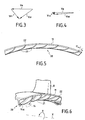
- the speed diagram of FIG. 3 shows that the relative speed Vr 1 of the air in the vicinity of the holes 14, relative to the periphery of the upstream disc 3 is relatively high.
- Va 1 indicates the absolute speed of the air and
- Ve represents the speed of the rim of the disc 3.
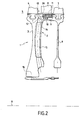
- Figure 2 shows the same compressor 1 equipped with means fixed guide 20 intended to imprint the air circulating in the groove 12 between the gap 13 and the holes 14 a vortex movement centripetal in the direction of rotation of the compressor 1.
- the air has an absolute speed Va 2 whose standard is equal to the standard of the absolute speed Va 1 , but which is substantially directed tangentially to the periphery of the outer shell 9, so that the speed relative Vr 2 of the air relative to the upstream disc 3 is significantly lower than the relative speed Vr 1 of the prior art, as shown in FIG. 4.
- the means guide 20 are arranged in the groove 12 under the upstream part of the inner platforms 11 of the straightening vanes 8.
- These guide means 20 comprise a plurality of profiles blade 21 or fins regularly distributed around the axis of rotation X of compressor 1 and whose leading edges 22 extend at least in part in the interstice 13.
- the angle of attack ⁇ of these profiles 21 is determined as a function of tangential speed and radial speed local air passing through gap 13.
- the airfoil profiles 21 are drawn in such a way that the air entering through the gap 13 and flowing between the airfoil profiles 21 comes out with a speed Va 2 , represented by an arrow or vector in FIGS. 4 and 6, substantially tangential to the drive speed Ve of the rotor, in order to significantly reduce the relative speed Vr 2 of the air entering the holes 14.
Landscapes
- Engineering & Computer Science (AREA)
- Mechanical Engineering (AREA)
- General Engineering & Computer Science (AREA)
- Physics & Mathematics (AREA)
- Thermal Sciences (AREA)
- Structures Of Non-Positive Displacement Pumps (AREA)
Abstract
Description
Claims (6)
- Compresseur axial de turbomachine équipé d'un dispositif (2) de prélèvement centripète d'air dans la veine (5) dudit compresseur, cet air étant destiné au refroidissement de la turbine, ledit compresseur comportant deux couronnes d'aubes mobiles (4, 7) qui s'étendent radialement vers l'extérieur à la périphérie de deux disques consécutifs (3, 6) assemblés par une virole extérieure (9) munie de perçages (14) et une couronne d'aubes redresseuses (8) fixes disposée dans la veine (5) entre lesdits deux couronnes d'aubes mobiles, lesdits perçages servant d'entrées d'air audit dispositif de prélèvement et débouchant dans une gorge annulaire (12) prévue sous l'interstice (13) séparant les plates-formes intérieures (11) des aubes redresseuses (8) de la jante du disque amont, ladite gorge communiquant avec ladite veine par ledit interstice, caractérisé en ce que la gorge (12) est équipée de moyens de guidage fixes (20) imprimant au flux d'air circulant dans ladite gorge (12) un mouvement tourbillonnaire centripète dans le sens de rotation du compresseur afin de diminuer la vitesse relative de l'air entrant dans les perçages (14) par rapport auxdits perçages en rotation.
- Compresseur selon la revendication 1, caractérisé par le fait que lesdits moyens de guidage sont disposés au moins en partie sous les plates-formes intérieures (11) des aubes redresseuses (8).
- Compresseur selon la revendication 2, caractérisé par le fait que lesdits moyens de guidage de l'air dans la gorge comportent une pluralité de profils d'aubage (21) régulièrement répartis autour de l'axe de rotation (X) dudit compresseur.
- Compresseur selon la revendication 3, caractérisé par le fait que les bords d'attaque (22) des profils d'aubage (21) s'étendent au moins en partie dans l'interstice (13).
- Compresseur selon la revendication 4, caractérisé par le fait que l'angle d'attaque (α) des profils est déterminé en fonction de la vitesse tangentielle et de la vitesse radiale locale de l'air passant par l'interstice.
- Compresseur selon l'une quelconque des revendications 1 à 5, caractérisé par le fait que le dispositif de prélèvement (20) comporte des canaux de prélèvement (15) ménagés dans le disque amont (3).
Applications Claiming Priority (2)
| Application Number | Priority Date | Filing Date | Title |
|---|---|---|---|
| FR0200519A FR2834758B1 (fr) | 2002-01-17 | 2002-01-17 | Dispositif pour redresser l'air d'alimentation d'un prelevement centripete dans un compresseur |
| FR0200519 | 2002-01-17 |
Publications (2)
| Publication Number | Publication Date |
|---|---|
| EP1329639A1 true EP1329639A1 (fr) | 2003-07-23 |
| EP1329639B1 EP1329639B1 (fr) | 2008-03-12 |
Family
ID=8871319
Family Applications (1)
| Application Number | Title | Priority Date | Filing Date |
|---|---|---|---|
| EP03290061A Expired - Lifetime EP1329639B1 (fr) | 2002-01-17 | 2003-01-10 | Dispositif de prélèvement centripète |
Country Status (6)
| Country | Link |
|---|---|
| US (1) | US6908278B2 (fr) |
| EP (1) | EP1329639B1 (fr) |
| CA (1) | CA2416157C (fr) |
| DE (1) | DE60319607T2 (fr) |
| FR (1) | FR2834758B1 (fr) |
| RU (1) | RU2295656C2 (fr) |
Families Citing this family (13)
| Publication number | Priority date | Publication date | Assignee | Title |
|---|---|---|---|---|
| US7686576B2 (en) * | 2006-10-24 | 2010-03-30 | General Electric Company | Method and apparatus for assembling gas turbine engines |
| US7661924B2 (en) * | 2007-03-28 | 2010-02-16 | General Electric Company | Method and apparatus for assembling turbine engines |
| RU2451840C2 (ru) * | 2010-06-21 | 2012-05-27 | Открытое акционерное общество "Авиадвигатель" | Ротор компрессора газотурбинного двигателя |
| DE102010063071A1 (de) * | 2010-12-14 | 2012-06-14 | Rolls-Royce Deutschland Ltd & Co Kg | Kühlvorrichtung für ein Strahltriebwerk |
| US20130177430A1 (en) * | 2012-01-05 | 2013-07-11 | General Electric Company | System and method for reducing stress in a rotor |
| US9121413B2 (en) * | 2012-03-22 | 2015-09-01 | General Electric Company | Variable length compressor rotor pumping vanes |
| US9091173B2 (en) * | 2012-05-31 | 2015-07-28 | United Technologies Corporation | Turbine coolant supply system |
| US9039357B2 (en) * | 2013-01-23 | 2015-05-26 | Siemens Aktiengesellschaft | Seal assembly including grooves in a radially outwardly facing side of a platform in a gas turbine engine |
| CN109209980B (zh) * | 2017-06-30 | 2020-06-05 | 中国航发商用航空发动机有限责任公司 | 一种用于轴流压气机的导流板 |
| RU189794U1 (ru) * | 2017-08-29 | 2019-06-04 | Акционерное общество "Объединенная двигателестроительная корпорация" (АО "ОДК") | Ротор компрессора газотурбинного двигателя |
| RU2728550C1 (ru) * | 2019-09-05 | 2020-07-31 | Акционерное общество "Объединенная двигателестроительная корпорация" (АО "ОДК") | Устройство отбора воздуха в роторе компрессора турбореактивного двигателя |
| WO2022066471A1 (fr) | 2020-09-22 | 2022-03-31 | General Electric Company | Turbomachine et système de fonctionnement de compresseur |
| CN113006880B (zh) * | 2021-03-29 | 2022-02-22 | 南京航空航天大学 | 一种用于涡轮叶片端壁的冷却装置 |
Citations (4)
| Publication number | Priority date | Publication date | Assignee | Title |
|---|---|---|---|---|
| GB712051A (en) * | 1951-10-10 | 1954-07-14 | Rolls Royce | Improvements in or relating to axial-flow fluid machines |
| US3085400A (en) * | 1959-03-23 | 1963-04-16 | Gen Electric | Cooling fluid impeller for elastic fluid turbines |
| FR2609500A1 (fr) * | 1987-01-14 | 1988-07-15 | Snecma | Disque de compresseur de turbomachine avec accelerateur centripete pour l'aspiration d'air de refroidissement de la turbine |
| FR2614654A1 (fr) * | 1987-04-29 | 1988-11-04 | Snecma | Disque de compresseur axial de turbomachine a prelevement d'air centripete |
Family Cites Families (4)
| Publication number | Priority date | Publication date | Assignee | Title |
|---|---|---|---|---|
| US2618433A (en) * | 1948-06-23 | 1952-11-18 | Curtiss Wright Corp | Means for bleeding air from compressors |
| SU1746078A1 (ru) * | 1990-04-09 | 1992-07-07 | Курский Политехнический Институт | Компрессорна установка |
| US5475313A (en) | 1994-09-20 | 1995-12-12 | Dykes; Wallace E. | Primary charge roller evaluator |
| RU2121082C1 (ru) * | 1996-02-13 | 1998-10-27 | Акционерное общество "Авиадвигатель" | Статор компрессора газотурбинного двигателя |
-
2002
- 2002-01-17 FR FR0200519A patent/FR2834758B1/fr not_active Expired - Fee Related
-
2003
- 2003-01-10 DE DE60319607T patent/DE60319607T2/de not_active Expired - Lifetime
- 2003-01-10 EP EP03290061A patent/EP1329639B1/fr not_active Expired - Lifetime
- 2003-01-15 CA CA2416157A patent/CA2416157C/fr not_active Expired - Lifetime
- 2003-01-16 US US10/345,184 patent/US6908278B2/en not_active Expired - Lifetime
- 2003-01-17 RU RU2003102223/06A patent/RU2295656C2/ru active
Patent Citations (4)
| Publication number | Priority date | Publication date | Assignee | Title |
|---|---|---|---|---|
| GB712051A (en) * | 1951-10-10 | 1954-07-14 | Rolls Royce | Improvements in or relating to axial-flow fluid machines |
| US3085400A (en) * | 1959-03-23 | 1963-04-16 | Gen Electric | Cooling fluid impeller for elastic fluid turbines |
| FR2609500A1 (fr) * | 1987-01-14 | 1988-07-15 | Snecma | Disque de compresseur de turbomachine avec accelerateur centripete pour l'aspiration d'air de refroidissement de la turbine |
| FR2614654A1 (fr) * | 1987-04-29 | 1988-11-04 | Snecma | Disque de compresseur axial de turbomachine a prelevement d'air centripete |
Also Published As
| Publication number | Publication date |
|---|---|
| FR2834758B1 (fr) | 2004-04-02 |
| US20030133787A1 (en) | 2003-07-17 |
| DE60319607T2 (de) | 2009-04-02 |
| CA2416157A1 (fr) | 2003-07-17 |
| CA2416157C (fr) | 2011-05-17 |
| EP1329639B1 (fr) | 2008-03-12 |
| DE60319607D1 (de) | 2008-04-24 |
| RU2295656C2 (ru) | 2007-03-20 |
| US6908278B2 (en) | 2005-06-21 |
| FR2834758A1 (fr) | 2003-07-18 |
Similar Documents
| Publication | Publication Date | Title |
|---|---|---|
| EP2281108B1 (fr) | Dispositif de prélèvement d'air d'un compresseur d'une turbomachine | |
| CA2764408C (fr) | Turbomachine comprenant des moyens ameliores de reglage du debit d'un flux d'air de refroidissement preleve en sortie de compresseur haute pression | |
| CA2722162C (fr) | Rotor de compresseur d'une turbomachine comportant des moyens de prelevement d'air centripete | |
| EP2337929B1 (fr) | Ventilation d'une turbine haute-pression dans une turbomachine | |
| US5758500A (en) | Exhaust gas turbochanger for an internal combustion engine | |
| US7097432B1 (en) | Sliding vane turbocharger with graduated vanes | |
| CA2416157C (fr) | Dispositif pour redresser l'air d'alimentation d'un prelevement centripete dans un compresseur | |
| RU2519009C2 (ru) | Стравливатель воздуха, имеющий инерциальный фильтр в тандемном роторе компрессора | |
| CA2715209C (fr) | Ventilation d'une roue de turbine dans une turbomachine | |
| EP1329591A1 (fr) | Disque de compresseur axial de turbomachine à prélèvement d'air centripète | |
| EP4081698B1 (fr) | Turbine comportant un espace secondaire interne équipé d'ailettes de correction de giration d'un flux d'air | |
| FR2481747A1 (fr) | Moteur a turbine a gaz comportant un dispositif perfectionne de refroidissement par air | |
| CN103026005A (zh) | 可变容量涡轮 | |
| WO2022189735A1 (fr) | Ensemble statorique de turbine | |
| FR2992679A1 (fr) | Tourillon de turbomachine comportant une couronne de recuperation d'un flux d'huile de lubrification avec une pluralite d'orifices d'evacuation d'huile de lubrification | |
| FR3036140B1 (fr) | Turbomachine d'aeronef a effet coanda | |
| FR3081027A1 (fr) | Turbomachine comportant un circuit de prelevement d'air | |
| EP3999779B1 (fr) | Chambre de combustion de turbomachine a volume constant | |
| EP3563047A1 (fr) | Moyeu de carter intermédiaire comprenant des canaux de guidage du flux de décharge formés par les ailettes de décharge | |
| WO2026052916A1 (fr) | Module pour une turbomachine d'aeronef | |
| FR3009348B1 (fr) | Diffuseur pour un compresseur radial ou mixte d'un moteur comprenant un flasque dont une partie est mobile | |
| FR3166165A1 (fr) | Module pour une turbomachine d’aeronef | |
| WO2026052917A1 (fr) | Module pour une turbomachine d'aeronef | |
| FR3160725A1 (fr) | Ensemble statorique de turbine de turbomachine d’aeronef, presentant un flux d’air de purge statorique a efficacite renforcee | |
| FR3168235A1 (fr) | Aubage pour une turbomachine d’aéronef |
Legal Events
| Date | Code | Title | Description |
|---|---|---|---|
| PUAI | Public reference made under article 153(3) epc to a published international application that has entered the european phase |
Free format text: ORIGINAL CODE: 0009012 |
|
| AK | Designated contracting states |
Designated state(s): AT BE BG CH CY CZ DE DK EE ES FI FR GB GR HU IE IT LI LU MC NL PT SE SI SK TR |
|
| AX | Request for extension of the european patent |
Extension state: AL LT LV MK RO |
|
| 17P | Request for examination filed |
Effective date: 20031009 |
|
| AKX | Designation fees paid |
Designated state(s): DE FR GB |
|
| RAP1 | Party data changed (applicant data changed or rights of an application transferred) |
Owner name: SNECMA |
|
| 17Q | First examination report despatched |
Effective date: 20061228 |
|
| GRAP | Despatch of communication of intention to grant a patent |
Free format text: ORIGINAL CODE: EPIDOSNIGR1 |
|
| GRAS | Grant fee paid |
Free format text: ORIGINAL CODE: EPIDOSNIGR3 |
|
| GRAA | (expected) grant |
Free format text: ORIGINAL CODE: 0009210 |
|
| AK | Designated contracting states |
Kind code of ref document: B1 Designated state(s): DE FR GB |
|
| REG | Reference to a national code |
Ref country code: GB Ref legal event code: FG4D Free format text: NOT ENGLISH |
|
| REF | Corresponds to: |
Ref document number: 60319607 Country of ref document: DE Date of ref document: 20080424 Kind code of ref document: P |
|
| PLBE | No opposition filed within time limit |
Free format text: ORIGINAL CODE: 0009261 |
|
| STAA | Information on the status of an ep patent application or granted ep patent |
Free format text: STATUS: NO OPPOSITION FILED WITHIN TIME LIMIT |
|
| 26N | No opposition filed |
Effective date: 20081215 |
|
| REG | Reference to a national code |
Ref country code: FR Ref legal event code: PLFP Year of fee payment: 14 |
|
| REG | Reference to a national code |
Ref country code: FR Ref legal event code: PLFP Year of fee payment: 15 |
|
| REG | Reference to a national code |
Ref country code: FR Ref legal event code: PLFP Year of fee payment: 16 |
|
| REG | Reference to a national code |
Ref country code: FR Ref legal event code: CD Owner name: SAFRAN AIRCRAFT ENGINES Effective date: 20170719 |
|
| PGFP | Annual fee paid to national office [announced via postgrant information from national office to epo] |
Ref country code: GB Payment date: 20211216 Year of fee payment: 20 Ref country code: FR Payment date: 20211215 Year of fee payment: 20 |
|
| PGFP | Annual fee paid to national office [announced via postgrant information from national office to epo] |
Ref country code: DE Payment date: 20211215 Year of fee payment: 20 |
|
| REG | Reference to a national code |
Ref country code: DE Ref legal event code: R071 Ref document number: 60319607 Country of ref document: DE |
|
| REG | Reference to a national code |
Ref country code: GB Ref legal event code: PE20 Expiry date: 20230109 |
|
| PG25 | Lapsed in a contracting state [announced via postgrant information from national office to epo] |
Ref country code: GB Free format text: LAPSE BECAUSE OF EXPIRATION OF PROTECTION Effective date: 20230109 |