BACKGROUND OF THE INVENTION
Field of the Invention
The present invention relates to a cam follower with roller, and more
particularly, to a cam follower with roller that is incorporated into a valve
mechanism of an internal combustion engine of a vehicle.
Description of the Background Art
To increase durability and maintenability of an engine valve system,
it is necessary to address the problems related to abrasion and insufficient
lubrication of a cam and a follower on a cam shaft.
To prevent abrasion of the valve system, a hydraulic lash adjuster
has been practically utilized in an OHV-type engine, and recently, use of a
rolling bearing for the follower has rapidly increased in order to reduce
abrasion and friction loss of the cam and follower.
A cam is a portion where lubrication easily dies away among other
engine components, and a contact surface thereof is called a boundary
lubrication area. In a cam follower with roller used under such
circumstances, the cam is in contact with the roller basically by rolling
contact. However, the rolling contact involves sliding, since absolute
rolling movement is hindered by abrupt variations in the load applied onto
the roller and by changes in the rolling speed of the roller due to the shape
of the cam. Thus, peeling or smearing, i.e. surface damage, occurs on an
outer diameter rolling surface of the roller in connection with the
lubricating conditions (amount and temperature of oil, debris) and surface
roughness of the opposing cam, resulting in a short life.
Moreover, a supporting shaft rotatably supporting the roller is
limited in the loaded zone, and thus a very large pressure is applied onto
the surface of the supporting shaft, resulting in shorter rolling fatigue life
compared to that of the roller or a bearing. Therefore, increase of rolling
fatigue life has been desired.
The bearing rotatably supporting the roller is generally a full type
roller bearing, which generates skew and relative sliding, so that the
bearing is also subjected to surface damage such as peeling and smearing.
It is noted that SUJ2 has conventionally been used for the material
of such roller, supporting shaft and bearing.
SUMMARY OF THE INVENTION
An object of the present invention is to provide a cam follower with
roller having a roller, a supporting shaft rotatably supporting the roller and
a rolling element that are made of heat-resisting, peeling-resisting and
smearing-resisting materials, and capable of increasing rolling fatigue life
and reducing surface damage under high temperature conditions.
According to the present invention, in a cam follower with roller
including a cam follower body having a roller supporting portion integrated
into the cam follower body, a supporting shaft of which both ends are fixed
to the roller supporting portion, and a roller rotatably supported on the
supporting shaft with a plurality of needle rollers interposed; at least one of
the supporting shaft, needle roller and roller is formed of heat-resisting
steel.
According to a cam follower with roller of the present invention, at
least one of the supporting shaft, needle roller and roller is formed of the
heat-resisting steel, so that the heat resistance can be improved and
surface damage such as smearing and peeling can be prevented, resulting
in increase of rolling fatigue life under high temperature conditions.
In the cam follower with roller, preferably, the both ends of the
supporting shaft is caulked to be fixed to the roller supporting portion.
Thus, the both ends of the supporting shaft are caulked to be fixed to
the roller supporting portion, and this caulking and fixing work can be
performed merely by notching an end surface of the supporting shaft.
Therefore, no impact is applied onto the roller supporting portion, so that
the cam follower would not be deformed at assembling.
In the cam follower with roller, preferably, a rolling contact surface
on which the needle roller rolls, of an outer circumferential surface of the
supporting shaft, is subjected to high frequency quenching so as to have a
surface hardness of at least HV 650, and the both ends of the supporting
shaft is subjected to no quenching so as to have a surface hardness of at
least HV 200 and at most HV 280.
Since the rolling contact surface has a surface hardness of at least
HV 650, it can remain intact when the needle roller rolls, without the
supporting shaft being deformed due to abrasion. Furthermore, both end
surfaces of the supporting shaft has a surface hardness in the range
between HV 200 and HV 280, so that the end surfaces can be notched at
assembling to enlarge the edge portion. Such a caulking process generates
no crack at the ends, allowing the supporting shaft to be easily and firmly
fixed to the cam follower body.
In the cam follower with roller, preferably, the supporting shaft is
through-quenched and is press-fit to the roller supporting portion.
Thus, the supporting shaft is through-quenched, allowing the
hardness to be higher. Furthermore, the supporting shaft is press-fit to
the roller supporting portion, so that the supporting shaft can be fixed to
the roller supporting portion even if the supporting shaft is produced by the
through quenching which allows no caulking for fixing.
In the cam follower with roller, preferably, the supporting shaft is
through-quenched and is fixed to the roller supporting portion in the axial
direction of the supporting shaft with a snap ring interposed.
Thus, the supporting shaft is through-quenched, allowing the
hardness to be higher. Furthermore, the supporting shaft is fixed by the
snap ring, so that the supporting shaft can be fixed to the roller supporting
portion without press-fitting or caulking work.
In the cam follower with roller, preferably, the roller is made of heat-resisting
steel.
In particular, the roller is in rolling-contact with the cam while
sliding, and thus the sliding or tangential stress may act onto the roller to
increase the temperature on the roller surface, or shear heating occurs in
lubrication oil to reduce the thickness of an oil film. This may easily cause
surface damage such as peeling and smearing. Such surface damage can,
however, be prevented by using the heat-resisting steel for the roller.
In the cam follower with roller, preferably, the heat-resistant steel is
made of a steel material at least containing as alloy elements in a matrix,
by mass %, at least 0.6% and at most 1.3% of C(carbon), at least 0.3% and
at most 3.0% of Si(silicon), at least 0.2% and at most 1.5% of
Mn(manganese), at most 0.03% of P(phosphorus), at most 0.03% of
S(sulfur), at least 0.3% and at most 5.0% of Cr(chromium), at least 0.1%
and at most 3.0% of Ni(nickel), at most 0.050% of Al(aluminum), at most
0.003% of Ti(titanium), at most 0.0015% of O(oxygen) and at most 0.015%
of N(nitrogen), and a remaining part of Fe(iron) and an unavoidable
impurity.
The use of the steel material allows rolling fatigue life to be
elongated by quenching and tempering, under the environment
contaminated with debris, without a carbonitriding process. Thus,
carbonitriding can be dispensed with, reducing the manufacturing cost.
Moreover, the steel material is superior in its heat resistance, peeling-resisting
property and smearing-resisting property, so that rolling fatigue
life can be increased and surface damage can be reduced under high
temperature conditions.
The reasons for limitations of each component indicated above will be
described below.
In the cam follower with roller, preferably, the steel material is
formed by one of quenching and carburizing processes followed by a
tempering process.
Each component of the cam follower with roller used in a high-temperature
range as in the present invention is subjected to the tempering
process at a temperature equal to or higher than an environment
temperature, in order to stabilize the size of each component under the
environment of use.
In the cam follower with roller, preferably, an effective hardened
portion with a hardness of at least HV 550 has a depth of at least 1.0 mm,
in a rolling contact surface on which the needle roller rolls, of an outer
circumferential surface of the supporting shaft.
Thus, a sufficient hardness can be attained for the surface on which
the needle roller rolls.
In the cam follower with roller, preferably, the supporting shaft is
made of the heat-resistant steel.
This limits a loaded zone, and a very large pressure is applied on the
surface, so that rolling fatigue life can be increased even in the supporting
shaft having a strict condition of rolling fatigue life.
In the cam follower with roller, preferably, the needle roller is made
of the heat-resistant steel, is quenched and hardened to a core, and has a
surface hardness of at least HV 650.
This allows the peeling-resistant property and smearing-resistant
property to be improved even in the needle roller at which skew and
relative sliding occurrs at the time of rolling.
In the cam follower with roller, preferably, the roller is quenched and
hardened to a core, and has a surface hardness of at least HV 650.
This can assure a sufficient hardness in rolling.
In the cam follower with roller, preferably, an infinite number of
microscopic concave recesses are randomly formed on an outer surface of
the roller. When surface roughness of the outer surface of the roller
obtained in each of axial and circumferential directions is indicated by a
parameter RMS, a ratio (RMS(L)/RMS(C)) of axial surface roughness
RMS(L) to circunferential surface roughness RMS(C) is at most 1.0, and a
parameter SK value of the surface roughness is at most - 1.6.
Thus, even under a condition in which roughness is inferior on the
finished surface of the opposing cam, an excellent ability of forming an oil
film can be attained so that a sufficient thickness of the oil film can be
secured, and therefore, the rolling contact portion can be prevented, as
much as possible, from being in contact with metal. Furthermore, the
surface of the rolling contact portion that is in contact with metal is
reduced, so that the outer diameter of the cam follower can be free from
surface damage, peeling and smearing, as well as unusual abrasion and
separation therefrom. Therefore, durability can be increased.
The foregoing and other objects, features, aspects and advantages of
the present invention will become more apparent from the following
detailed description of the present invention when taken in conjunction
with the accompanying drawings.
BRIEF DESCRIPTION OF THE DRAWINGS
Fig. 1 is a schematic front view showing a structure of the cam
follower with roller according to one embodiment of the present invention;
Fig. 2 is a schematic section view taken along the line II-II in Fig. 1
in the direction of the arrows;
Fig. 3 is a schematic section view showing a structure in which a
roller shaft is formed to have a solid structure and is caulked to be fixed;
Figs. 4A and 4B are a vertical section view of the roller shaft shown
in Fig. 3, and a graph showing the distribution of hardness of the roller
shaft, respectively;
Fig. 5 is a schematic section view showing a structure of the roller
shaft when fixed by a snap ring;
Fig. 6 schematically shows a structure of a two-cylinder test
machine;
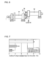
Fig. 7 shows the result of a peeling test;
Fig. 8 shows the result of a smearing test; and
Figs. 9A and 9B are a front view and a side view, respectively,
showing a device performing a 12 point-contact life test.
DESCRIPTION OF THE PREFERRED EMBODIMENTS
Embodiments of the present invention will be described below.
Referring to Figs. 1 and 2, one end of a cam follower body 1 is
rotatably supported onto a cam follower shaft 5 with bearing metal or the
like interposed.
An adjust screw 7 is mounted in a helical manner to the other end of
cam follower body 1. Adjust screw 7 is fixed by a lock nut 8, and a lower
end thereof is in contact with an upper end of a protruded rod 9 of a suction
valve or an exhaust valve of an internal combustion engine. Protruded rod
9 is biased by resilience of a spring 10.
A roller supporting portion 1a is integrally formed in a bifurcated
manner at the middle portion of cam follower body 1. Both ends of roller
shaft 2 are fixed to a shaft hole 1b provided at the bifurcated roller
supporting portion 1a by press-fitting or by a snap ring. A roller 4 is
rotatably supported in the middle of an outer circumferential surface of
roller shaft 2 with a needle roller 3 interposed. The outer circumferential
surface of roller 4 is pressed by resilience of spring 10 to be in contact with
a cam surface of cam 6.
By such an arrangement, rotation of cam 6 allows cam follower body
1 to rotate around cam follower shaft 5 with roller 4 interposed, to open and
close the suction valve or exhaust valve attached at a tip end of protruded
rod 9.
It is noted that the internal engine includes, for example, a piston
reciprocating within a cylinder, and an ignition plug igniting the fuel
compressed by the piston.
At least one of roller shaft 2, needle roller 3 and roller 4 is formed of
heat-resisting steel, and roller shaft 2 has a hollowed shape as a result of
through quenching. A switching pin (not shown) is inserted into the
hollow of roller shaft 2 to allow various opening and closing functions of a
valve. Further, hollow inside of roller shaft 2 contributes to weight saving.
It is noted that roller shaft 2 may have a shape other than the
through-quenched hollowed shape, e.g. a solid structure, and both ends
thereof may be caulked to be fixed to roller supporting portion 1a, as shown
in Fig. 3. This caulking is performed by notching an end surface 2a of
roller shaft 2 to form a caulking groove 2b after roller shaft 2 is fit into
shaft hole 1b provided at the bifurcated roller supporting portion 1a. By
forming caulking groove 2b, the edge portion of roller shaft 2 is enlarged
and the inner surface of shaft hole 1b is biased by resilience, so that roller
shaft 2 is firmly fixed to shaft hole 1b.
Referring to Figs. 4A and 4B, a middle portion 2c of roller shaft 2 is a
portion hardened by high-frequency quenching, whereas both ends 2d are
unquenched portions for which no quenching has been performed. It is
noted that a part or all of the outer circumferential surface of middle
portion 2c is to be a so-called rolling contact surface on which needle roller
3 rolls.
Referring to Fig. 4B, in the distribution of hardness of the roller
shaft 2 surface, middle portion 2c has the Vickers hardness of at least HV
650, whereas the softened portions of both ends 2d have the Vickers
hardness in the range between HV 200 and HV 280. Therefore, middle
portion 2c has a sufficient hardness for a rolling contact surface of needle
roller 3, whereas softened portions 2d are soft enough for caulking.
It is noted that roller shaft 2 is fixed in different ways depending on
the material of the bifurcated roller supporting portion 1a and the heat
treatment method of roller shaft 2, as shown in the table below.
| Material of supporting portion | Heat treatment method of supporting shaft |
| | High-frequency quenching | Through quenching |
| | Hollowed shaft | Solid shaft | Hollowed shaft | Solid shaft |
| Carburized steel | Caulking | Caulking | Snap ring | Snap ring |
| Aluminum alloy | Caulking | Caulking | Press-fitting | Press-fitting |
When through-quenched, roller shaft 2 cannot be caulked and fixed
to the bifurcated roller supporting portion 1a. Thus, as shown in Fig. 5, an
annular groove 2e is formed at one supporting portion of the bifurcation
(inner diameter) and on roller shaft 2, and a snap ring is pre-mounted into
annular groove 2e of roller shaft 2. Roller shaft 2 is inserted into roller
supporting portion 1a while the diameter of the snap ring is reduced, and
then the snap ring is restored by resilience at the position where annular
groove 2e is arranged, to allow roller shaft 2 to be fixed in the direction of
axis thereof. This can eliminate the need for press-fitting or caulking
work to fix roller shaft 2.
Here, though roller shaft 2 can be fixed in the direction of axis, roller
shaft 2 may possibly creeps (rotates). In particular, when an aluminum
alloy is used as a material of the bifurcated roller supporting portion 1a for
the purpose of weight saving, disadvantageous abrasion occurs due to the
creeping. When roller shaft 2 is through-quenched allowing no caulking,
the roller shaft is press-fit into the bifurcated roller supporting portion 1a.
The first heat-resistant steel according to the present invention is a
steel material at least containing in the matrix, as alloy elements, at least
0.6 % and at most 1.3 % of C, at least 0.3 % and at most 3.0 % of Si, at least
0.2 % and at most 1.5 % of Mn, at most 0.03 % of P, at most 0.03 % of S, at
least 0.3 % and at most 5.0 % of Cr, at least 0.1 % and at most 3.0 % of Ni,
at most 0.050 % of Al, at most 0.003 % of Ti, at most 0.0015 % of O, and at
most 0.015 % of N, all by mass %, the remaining part having Fe and an
unavoidable impurity (such a steel material is referred to as "invention
steel 1" in the embodiments of the present invention).
Moreover, the heat-resistant steel material is subjected to quenching
or carbonitriding followed by a tempering process.
Furthermore, as another heat-resistant steel, a steel material may be
used at least containing, in the matrix, at least 0.95 % and at most 1.10 %
of C, at least 1 % and at most 2 % of Si or Al, at most 1.15 % of Mn, and at
least 0.90 % and at most 1.60 % of Cr, all by mass %; the remaining part
having Fe and an unavoidable impurity; and at most 13 ppm of O. A
product formed by such a material is quenched and thereafter tempered at
a high temperature in the range between 230 and 300 °C to have retained
austenite of at most 8 % by volume and a hardness of at least HRC 59 (such
a steel material is referred to as "invention steel 3" in the embodiments of
the present invention).
In addition, as a further heat-resisting steel, a steel material having
a composition within the range as indicated in Table 2 below may be used
(referred to as "invention steel 2" in the embodiments of the present
invention).
| C | Mo | Cr | V | Mn | Si | Co | W | Cu | Ni | P | S |
| 0.77 | 4.00 | 3.75 | 0.90 | at most | at most | at most | at most | at most | at most | at most | at most |
| -0.85 | -4.50 | -4.25 | -1.10 | 0.35 | 0.25 | 0.25 | 0.25 | 0.10 | 0.10 | 0.015 | 0.015 |
| (All values in the table indicated by mass %) |
At the rolling contact surface on which needle roller 3 rolls, of the
outer circumferential surface of roller shaft 2, the effective hardened
portion with a hardness of at least HV 550 preferably has a depth of at
least 1.0 mm. Moreover, needle roller 3 is made of heat-resisting steel,
which is preferably quenched and hardened through to the core portion and
has a surface hardness of at least HV 650. Roller 4 is preferably quenched
and hardened through to the core portion and has a surface hardness of at
least HV650.
An infinite number of microscopic concave recesses are formed on the
outer circumferential surface of roller 4. When surface roughness of the
outer circumferential surface of roller 4 is obtained in the directions of axis
and circumference respectively and indicated by a parameter RMS, the
ratio (RMS(L)/RMS(C)) of the surface roughness in the axial direction
RMS(L) to that in the circumferential direction RMS(C) is preferably equal
to or lower than 1.0, whereas a parameter SK value of the surface
roughness is preferably equal to or lower than -1.6.
Here, parameter RMS is a value of a square root obtained as follows:
each square of deviation in the range from the center line to a roughness
curve f(x) is integrated in a section of a measurement length, and the
squares in the section are averaged, to obtain the square root of the average.
This parameter value is also called a roughness indicated by Root Mean
Square. RMS can be calculated from a section curve and a roughness
curve, which are enlarged for recording, by numerical calculation.
As a surface treatment process for attaining a roughness condition of
the outer circumferential surface described above, special barrel polishing
may be applied to obtain a desirable finished surface.
In the treatment method, the roller surface is provided with concave
and convex portions randomly formed thereon using a chip by, e.g. a
centrifugal fluidizing barrel polishing, followed by washing, and is further
subjected to a surface finishing process using barrel polishing so that the
microscopic convex portions on the surface are removed or rounded,
resulting in an infinite number of microscopic concave portions left on the
roller surface. Such processing, which is performed for the surface
roughness of the roller outer circumferential surface to attain a desired
value, is hereinafter referred to as HL processing.
The parameter SK value is obtained by quantifying skewness of the
distribution curve of the surface roughness, i.e. asymmetry of distribution
of the concave and convex portions when the centerline of the roughness is
taken as a boundary. A negative SK value indicates that there are a
larger number of concave portions (valleys) below the centerline, whereas a
positive SK value indicates that there are a larger number of convex
portions (protrusions) above the centerline. The parameter SK value of
the surface roughness is represented by the definitional equation below.
SK = ∫ (X - xG)3 P(X) dx/σ3
The average height of the roughness in the definitional equation for
obtaining the SK value means an absolute value taken from a reference of
the centerline in each individual case. Here, the difference between the
center line and the average height is discussed. When the total area of
protrusions above a line is the same as that of valleys below the line, the
line is defined as the center line of roughness. However, this is only a
hypothetical line, and an absolute value taken from a reference is required
in order to obtain the SK value. This absolute value is defined as the
average height.
The parameter SK value is set to have a mean of at most -1.6 in both
the circumferential and axial directions, and thus a number of microscopic
concave portions are present below the center line. The numerical value of
the surface roughness in directions, i.e. RMS(L)/RMS(C), is defined to be at
most 1.0, so that an effective range for forming an oil film can be obtained
in both the shape and distribution of the surface recesses.
The parameter SK value indicated above serves as a guideline for
finding a degree of asymmetry of the concave and convex distribution. In
an example of the curve of roughness on a general polished surface, the SK
value is close to 0 in a symmetric distribution of concave and convex
portions, is negative when the concave and convex distribution on the
surface is biased to the recess side, and is positive when the distribution is
biased otherwise.
By defining the surface roughness of the outer surface of roller 4 as
described above, even under a condition in which roughness on the finished
surface of the opposing cam is inferior, the outer surface of roller 4 can
ensure a superior ability of forming an oil film and a sufficient thickness of
the oil film. Therefore, a contact portion can have minimum contact with
metal.
The area of the rolling contact portion that is in contact with metal is
made smaller as described above, so that surface damage, i.e. peeling and
smearing as well as unusual abrasion and separation therefrom, can be
prevented. Therefore, durability can be improved.
Experimental examples of the present invention will be described
below.
(1) Surface-damage-resisting property (peeling-resisting property,
smearing-resisting property) test
When low viscosity oil is used, or when viscosity is reduced due to
increased temperature of lubrication oil, it is difficult for an oil film to be
formed on a bearing raceway surface, resulting in easy contact with metal.
Under such a condition, surface damage called peeling (damage due to
microscopic separations and surface cracks being closely formed) may occur.
Moreover, when the rate of relative sliding is high on the contact surface,
heat due to the contact with metal generates local adhesion, which may
cause damage called smearing.
For such surface damage, evaluation was performed using a two
cylinder test machine shown in Fig. 6. Referring to Fig. 6, ring test pieces
34 and 35 having slow curvature to conform to cylindrical portions are
attached, respectively, to a driving shaft 31 and to a driven shaft 32 which
is parallel to driving shaft 31, and the cylindrical surfaces of the both test
pieces 34 and 35 are pressed to each other for rolling, to perform the
peeling and smearing tests.
Condition in the peeling test is indicated in Table 3 below.
| Peeling test condition |
| Test machine | 2-cylinder test machine |
| Tangential stress | Pmax = 2.3 GPa |
| Rotational speed | 2000 rpm |
| Lubrication | Turbine oil VG46 |
| Evaluation standard | Rate of area subjected to peeling |
It is noted that a polishing process is performed on cylindrical test
piece 34 on the driving side, whereas a superfinishing process is performed
on cylindrical test piece 35 on the driven side, before providing the test
pieces for the test.
In addition, the peeling-resisting property is evaluated by the rate of
the peeled area on the driven-side cylindrical test piece 35. The result is
shown in Fig. 7.
As can been seen from Fig. 7, the peeling occurence rate of invention
steel 1 is approximately one-eighth that of SUJ2, and invention steel 1 has
a superior property against surface damage. Moreover, the rate of the
area subjected to peeling is significantly low in invention steel 2, which also
has a superior property against surface damage.
This indicates that the use of heat-resisting steel such as invention
steel 1 or invention steel 2 improves the peeling-resisting property
compared to the case with SUJ2.
As for the smearing-resisting property, the rotational speed of the
cylinder on one side is increased to provide relative sliding to the rolling
contact portion of the two cylinders that are in contact with each other, to
measure a relative rotational speed until smearing occurs, and the relative
rotational speed at occurrence of smearing is used to evaluate the smearing
property. Condition of the smearing test is indicated in Table 4 below.
| Smearing test condition |
| Test machine | 2-cylinder test machine |
| Tangential stress | Pmax = 2.1 GPa |
| Rotational speed | Fixed side: 200 rpm Driven side: increased from 200 rpm in increments of 100 rpm |
| Lubrication | Turbine oil VG46 |
| Evaluation standard | Relative rotational speed at occurrence of smearing |
The result obtained with the test condition above is shown in Fig. 8.
As shown in Fig. 8, the relative rotational speed (sliding speed) at
occurrence of smearing is 1.4 times as high as that of SUJ2, indicating a
superior smearing property. Moreover, as for invention steel 2, the
relative rotational speed is approximately 1.3 times as high as that of SUJ2,
also indicating a superior smearing property.
This shows that the use of the heat-resisting steel such as invention
steel 1 or invention steel 2 improves the smearing-resisting property
compared to SUJ2.
(2) Strength of invention steel 1
A ring test piece with an outer diameter of 60 x an inner diameter of
45 × a width 15 (mm) is fabricated to be used for examining fracture
strength of the ring. Moreover, JIS No.3 test piece for Charpy impact test
(U notch) is used to examine impact strength and fracture toughness (K
Ic).
The result is indicated in Table 5 below.
Result of strength tests
Fracture strength of developed steel |
| Type of steel | Static fracture
strength of ring (kN) | Charpy impact value
(J/cm2) | Fracture toughness
(Mpa√m) |
| Invention steel 1 | 45.0 | 7.83 | 15.2 |
| SUJ2 | 45.0 | 5.54 | 15.0 |
As can be seen from the result indicated in Table 5, any property
value of invention steel 1 is almost the same as that of SUJ2, and therefore,
invention steel 1 can be practically used without a problem related to crack
strength.
(3) 12 point-contact life test
This test is performed as follows. Referring to Figs. 9A and 9B, a
driving wheel 23 is driven to be rotated while cylindrical test piece 21 of
12 x L22 is held between driving wheel 23 and a rigid ball 22 touching a
guide wheel 24, and the lifetime in such a condition (L10 life) is measured.
It is noted that Fig. 9A corresponds to Fig. 9B viewed in the direction of the
arrow denoted by IX.
The test condition is indicated in Table 6, and the value of life
obtained as a result of the test (L10 life) and the ratio of the L10 life are
indicated in Table 7. It is noted that the L10 life means the number of
loads that can be applied with 90 % of test-piece samples undamaged.
| Life test condition |
| Test machine | Point-contact-type life test machine |
| Test piece | 12 x ℓ22 straight roller |
| Opposing rigid ball | 19.525 (3/4) |
| Tangential stress | Pmax = 5.88 GPa |
| Load speed | 46240 times/min |
| Lubrication | Turbine VG68 circulating lubrication |
| Oil temperature | 90 °C |
| Result of 12 point-contact life test (× 104 for L10 life) |
| Type of steel | Heat treatment | L10 | L10 ratio |
| Invention steel 1 | High-frequency quenching | > 85193 | > 10.26 | > 10.76 |
| Through quenching | 60000 | 7.17 | 7.57 |
| SUJ2 | High-frequency quenching | 7921 | 0.95 | 1 |
| Through quenching | 8372 | 1 | 1.06 |
As can be seen from the result above, either high-frequency
quenched or through quenched, invention steel 1 has a significantly longer
life compared to SUJ2.
Moreover, compared to the case with SUJ2, invention steel 3 also has
improved peeling-resisting property, smearing-resisting property and L10
life.
It is appreciated from the description above that the use of the heat-resisting
steel such as invention steel 1, invention steel 2 and invention
steel 3 improves heat resistance, peeling-resisting property and smearing-resisting
property, resulting in longer life, compared to the conventionally-used
SUJ2.
It is noted that, irrespective of the composition experimented herein,
a steel that can obtain a characteristic similar to that of each of the
invention steels 1 to 3 above is considered to be a heat-resisting steel of the
present invention. The heat-resisting steel of the present invention has
peeling-resisting property, smearing-resisting property and L10 life that
are superior to those of SUJ2. Moreover, the heat-resisting steel of the
present invention has a peeling occurring rate of approximately 2.51/8 of
that of SUJ2, and a relative speed ratio of smearing occurrence of
approximately 1.3 times that of SUJ2 or higher.
According to the cam follower with roller of the present invention, at
least one of the supporting shaft, needle roller and roller is made of the
heat-resisting steel, so that heat resistance, peeling-resisting property and
smearing-resisting property can be improved while rolling fatigue life can
be elongated and surface damage is reduced under high temperature
conditions.
In addition, provision of so-called HL processing onto the outer
diameter surface of the roller can further improve resistance to surface
damage.
Although the present invention has been described and illustrated in
detail, it is clearly understood that the same is by way of illustration and
example only and is not to be taken by way of limitation, the spirit and
scope of the present invention being limited only by the terms of the
appended claims.