EP1329360B1 - Retractable running board - Google Patents
Retractable running board Download PDFInfo
- Publication number
- EP1329360B1 EP1329360B1 EP03250257A EP03250257A EP1329360B1 EP 1329360 B1 EP1329360 B1 EP 1329360B1 EP 03250257 A EP03250257 A EP 03250257A EP 03250257 A EP03250257 A EP 03250257A EP 1329360 B1 EP1329360 B1 EP 1329360B1
- Authority
- EP
- European Patent Office
- Prior art keywords
- running board
- selectively
- link
- additional
- retractable
- Prior art date
- Legal status (The legal status is an assumption and is not a legal conclusion. Google has not performed a legal analysis and makes no representation as to the accuracy of the status listed.)
- Expired - Lifetime
Links
- 230000007246 mechanism Effects 0.000 claims abstract description 48
- 230000033001 locomotion Effects 0.000 claims description 23
- 230000005540 biological transmission Effects 0.000 claims description 14
- 238000000034 method Methods 0.000 claims description 3
- 230000000712 assembly Effects 0.000 description 4
- 238000000429 assembly Methods 0.000 description 4
- 238000006073 displacement reaction Methods 0.000 description 4
- 230000002265 prevention Effects 0.000 description 3
- 230000004048 modification Effects 0.000 description 2
- 238000012986 modification Methods 0.000 description 2
- 241000755266 Kathetostoma giganteum Species 0.000 description 1
- 230000006835 compression Effects 0.000 description 1
- 238000007906 compression Methods 0.000 description 1
- 230000002153 concerted effect Effects 0.000 description 1
- 238000010276 construction Methods 0.000 description 1
- 230000009977 dual effect Effects 0.000 description 1
- 239000012530 fluid Substances 0.000 description 1
- 239000000463 material Substances 0.000 description 1
- 230000002441 reversible effect Effects 0.000 description 1
- 230000001360 synchronised effect Effects 0.000 description 1
Images





Classifications
-
- B—PERFORMING OPERATIONS; TRANSPORTING
- B60—VEHICLES IN GENERAL
- B60R—VEHICLES, VEHICLE FITTINGS, OR VEHICLE PARTS, NOT OTHERWISE PROVIDED FOR
- B60R3/00—Arrangements of steps or ladders facilitating access to or on the vehicle, e.g. running-boards
- B60R3/002—Running boards
-
- B—PERFORMING OPERATIONS; TRANSPORTING
- B60—VEHICLES IN GENERAL
- B60R—VEHICLES, VEHICLE FITTINGS, OR VEHICLE PARTS, NOT OTHERWISE PROVIDED FOR
- B60R3/00—Arrangements of steps or ladders facilitating access to or on the vehicle, e.g. running-boards
- B60R3/02—Retractable steps or ladders, e.g. movable under shock
Definitions
- the present invention relates to a retractable running board assembly for use with a vehicle.
- the generic US-A-5,697,626 describes running boards with selectively variable heights.
- the running board When the vehicle is being driven, the running board is raised vertically to improve the vehicle's ground clearance. Conversely, when the vehicle is stopped, the running board can be lowered to position the running board at a more convenient height for the passengers.
- the running board should be disposed laterally outwardly from the vehicle's entrances/doors such that the lower edge of the door opening, the running board, and the ground form laterally- and vertically-spaced steps like those in building stairways.
- disposing a running board fixed laterally outwardly from the vehicle for the passengers' convenience disadvantageously increases the vehicle's width.
- US-A-3,608,957 describes a running board designed to extend laterally outwardly when the vehicle's door is opened such that the running board is in a convenient laterally-outward position when the passengers need to use it to enter and exit the vehicle. Conversely, the running board is retracted laterally inwardly when the door is closed so that the vehicle has a narrower width during operation.
- the applicants are aware of a retractable running board developed by Amp Research of Irvine, California that moves both laterally and vertically between its extended and retracted positions. It is believed that two longitudinally spaced four-bar linkages connect the running board to the vehicle, and that an automatic actuator powers only one of the two linkages to extend the running board downwardly and outwardly when the vehicle's passenger door is opened.
- the second four-bar linkage is believed to move freely and therefore follows the movements of the first powered linkage as the powered movement of the first linkage is transferred through the length of the running board to the second linkage. Because the second linkage is not, itself, powered and cannot resist movement of the running board, the running board cannot be firmly held in place, especially when the weight of a passenger is exerted on the running board at a position far from the first powered linkage.
- the not prepublished WO-A-02/053416 describes a retractable running board assembly for use with a vehicle having a passenger compartment and a door opening providing access to the passenger compartment.
- the assembly comprises a mounting assembly secured to the motor vehicle and operatively connected to a U-shaped running board to move the running board between a retracted and a deployed position.
- the mounting assembly includes a plurality of pairs of arms pivotally mounted between a frame on the undercarriage of the vehicle and parts of the running board. Air or hydraulic cylinders are provided to move the running board.
- the not prepublished WO-A-02/085670 describes a retractable step for use with a vehicle having a stepping member with a stepping deck, a first arm, a second arm, a motor and a stop.
- the first and second arms each has a first end pivotally attached to the vehicle, and a second end pivotally attached to the stepping member.
- the motor is drivingly connected to the first arm such that rotation of the motor causes rotation of the first arm about its first end and moves the stepping member from a retracted position to an extended position, or vice versa.
- the stop is located within the range of motion of the second arm such that the second arm bears against the stop when the stepping member is in the extended position.
- the first and second arms are situated such that the first arm is loaded in compression and the second arm is loaded in tension when the stepping member is in the extended position and a load is placed upon it.
- the present invention seeks to provide a running board assembly having a backdrive prevention mechanism.
- a retractable running board assembly for use with a vehicle having a passenger compartment and a door opening providing access to the passenger compartment, the assembly comprising:
- the worm gear and worm wheel provide a backdrive prevention mechanism.
- the worm wheel of the selectively-operable driving mechanism's transmission is operatively connected to each of the first and second selectively actuated links such that, when the running board assembly is mounted in the operative position, selective operation of the driving mechanism rotates the worm wheel to actuate each of the selectively actuated links to move the running board between the retracted and extended positions.
- the at least one selectively-actuated link is constructed and arranged such that, when the running board assembly is mounted to the vehicle in the operative position, actuation of the link moves the running board between (a) the retracted position, (b) the extended position, and (c) a secondary extended position wherein the running board is moved upwardly from the primary extended position for facilitating passenger access to a roof of the vehicle.
- the vehicle includes an additional door opening and the running board assembly further comprises an additional elongated retractable running board having a non-circular cross-section perpendicular to a longitudinal direction thereof; wherein the running board moving assembly further comprises at least one additional selectively-actuated link connected between the additional running board and the anchor and movably supporting the additional running board, the link being constructed and arranged such that, when the running board assembly is mounted to the vehicle in the operative position, actuation of the additional link moves the additional running board in extending and retracting directions between (a) a retracted position, (b) an extended position wherein the running board is moved at least outwardly with respect to the vehicle from the retracted position for facilitating passenger entry into the passenger compartment via the additional door opening, the extending and retracting directions of the additional running board having both vertical and horizontal components, the additional link enabling the additional running board to maintain essentially the same orientation during movement between the extended and retracted position; and wherein the selectively-operable driving mechanism further comprises a second transmission having (a)
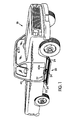
- FIG. 1 illustrates a vehicle 10 that has a retractable running board assembly 20 according to an embodiment of the invention.
- the retractable running board assembly 20 includes an anchor 24 mounted to a frame (or body) 25 of the vehicle 10 in an operative position below a passenger compartment of the vehicle 10.
- the vehicle 10 has a longitudinal direction that is defined by the direction of movement of the vehicle 10. While the running board assembly 20 in this embodiment is disposed along the passenger side of the vehicle 10, the running board assembly 20 may alternatively be disposed along a variety of other portions of the vehicle 10 such as the driver's side, the front, or the back. Further, the retractable running board assembly 20 may also be utilized in other types of vehicles, such as construction equipment or sport utility vehicles.
- anchor 24 and the frame 25 are illustrated as distinct elements, the anchor may be an integral part of the frame/body.
- the term anchor is a structural term used herein to encompass any structure mounting the assembly 20 to the vehicle 10.
- FIG. 2 is an enlarged perspective view of the retractable running board assembly 20.
- a longitudinally elongated retractable running board 26 is connected to the anchor 24 via a running board moving assembly 27.
- the board 26 has a non-circular cross-section perpendicular to its longitudinal direction. As illustrated, it is somewhat Z-shaped in cross-section.
- the running board moving assembly 27 includes a plurality of longitudinally spaced selectively-actuated links 28, 30, 32.
- the longitudinal direction of the running board 26 is generally parallel to a longitudinal direction of the vehicle 10. However, if the running board assembly 20 were disposed on the vehicle 10 in a position other than along the lateral sides, the running board 26 would not parallel the longitudinal direction of the vehicle 10.
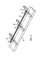
- the running board moving assembly also includes a selectively-operable driving mechanism that is operatively connected to each of the plurality of selectively-actuated links 28, 30, 32 such that selective operation of the selectively-operable driving mechanism concertedly actuates each of the selectively-actuated links 28, 30, 32 and moves the running board 26 between an extended position (as shown in FIGS. 1 and 2 ) and a retracted position (as shown in FIG. 3 ).
- the driving mechanism may be of any type, including a D.C. reversible electric motor, a fluid driven motor, or a manually operated input, such as a lever, a crank, a wheel, or a rotatable lug.
- each of the links 28, 30, 32 comprises a four-bar mechanism.
- a first leg of the four-bar mechanism is defined by the anchor 24.
- a second leg 36 connects to the first leg/anchor 24 for pivotal movement about a longitudinal axis 38 relative to the first leg/anchor 24.
- the longitudinal axis 38 is generally parallel to the longitudinal direction of the running board 26.
- a third leg 40 also pivotally connects to the first leg/anchor 24.
- a fourth leg 42 pivotally connects to the second and third legs 36, 40 and is mounted to the running board 26.
- the fourth leg 42 is preferably elongated so as to provide structural support to the running board 26.
- Actuation of the links 28, 30, 32 translationally moves the running board 26 along a generally arcuate or curved path that is generally perpendicular to the longitudinal axis 38.
- the motion of the running board 26 may also include a rotational component.
- Each four-bar mechanism comprises a parallelogram such that the path of the running board 26 has no rotational component and the running board 26 is always generally level. The running board 26 therefore moves downwardly and outwardly relative to the vehicle 10 and anchor 24 as it moves from its retracted position to its extended position.
- the running board 26 When in the extended position, the running board 26 is preferably disposed (a) at a height generally midway between ground level and a lower edge 43a of an adjoining door opening 43 of the vehicle 10 and (b) at a lateral position that is disposed at least partially outward from a side of the vehicle 10 in order to facilitate easy entrance into and exit from the vehicle 10.
- the running board assembly 20 does not touch the ground.
- the extended and retracted positions of the running board 26 are both vertically and horizontally offset from each other.
- the path of the running board may comprise one or more of horizontal movement, vertical movement, and rotational components.
- the four-bar mechanisms used as the links 28, 30, 32 are designed such that a stepping platform 44 defined by a top surface of the running board 26 is generally level when the running board 26 is in the extended position.
- the links 28, 30, 32 are preferably designed to hold the running board 26 as close to the vehicle 10 as possible when the running board 26 is in the retracted position.
- the running board moving assembly 27 includes a longitudinally elongated torque transmitting member 50 that is mounted to each of the second legs 36 of the links 28, 30, 32 for common rotation with the second legs 36 about the longitudinal axis 38, which is generally parallel to the longitudinal direction of the running board 26.
- the torque transmitting member 50 may be rotationally coupled to each of the second legs 36 using any appropriate method.
- the torque transmitting member 50 may have a square cross-section that fits into square holes in the second legs 36.
- a spline and keyway may be used to rotationally couple the torque transmitting member 50 to each of the second legs 36.
- the torque transmitting member 50 could also be welded to or formed integrally with the second legs 36.
- the torque transmitting member 50 is operatively connected to the motor 34 via a gear box 46.
- the gearbox 46 operates as a step-down mechanism such that the torque transmitting member 50 rotates substantially slower than the motor 34.
- the gear box 46 includes a worm gear operatively connected to the motor 34 and a worm wheel operatively connected to the torque transmitting member 50.
- the worm gear and wheel serve dual functions by stepping down the speed of the motor 34 (and stepping up the torque) and locking the torque transmitting member 50 and gear box 46 into fixed rotational positions when the motor 34 is not being operated.
- the pitch of a worm gear and wheel creates a frictional resistance that prevents a rotational force acting upon the worm wheel from rotating the worm gear (i.e., backdrive).
- the torque transmitting member 50, links 28, 30, 32, and running board 26 are locked into fixed positions, and hence the worm wheel and worm gear may be considered a backdrive prevention mechanism. Because each of the links 28, 30, 32 individually locks in place, the running board 26 is substantially immovable relative to the anchor 24 even when the weight of a passenger is exerted on a longitudinal end of the running board 26.
- the selectively-operable motor 34 is an electric motor that is operated with a conventional electrical control circuit. If the control circuit is automatically controlled, the circuit could selectively operate the motor 34 to extend the running board into its extended position when the vehicle 10 is placed in park, when the doors are opened, or when the ignition is turned off. Alternatively, if the control circuit is manually controlled, an operation switch could be placed within the cab of the truck to allow an operator to selectively control the extension position of the running board 26.
- the illustrated motor 34 is an electric rotational motor, other types of motors could be utilised.
- the motor 34 may be a linear motor, a hydraulic motor, a hydraulic cylinder, or a linear actuator.
- FIG. 4 illustrates an alternative embodiment of a retractable running board assembly 58, in which only two selectively-actuated links 28, 32 are used.
- two short torque transmitting members 60, 62 are rotationally coupled to the second legs 36 of the links 28, 32, respectively.
- Worm wheels 66 are rotationally coupled to each of the torque transmitting members 60, 62.
- Worm gears 68 mesh with each of the worm wheels 66.
- Each of the worm gears 68 is operatively connected to a motor 70 via a flexible torque transmitting cable 72 and a gear box 74.
- the flexible torque transmitting cable 72 preferably comprises a rotating inner cable mounted within an outer sheath.
- Each inner cable is operatively connected to a worm gear 68 and the gear box 74 in a conventional manner.
- the worm gears 68 and wheels 66 prevent the links 28, 32 from moving when the motor 70 is not being operated.
- the links are concertedly actuated to extend and retract the running board 26. Because flexible torque transmitting cables 72 connect the motor 70 to the links 28, 32 (as opposed to the rigid connection of the previous embodiment), the motor 70 may be mounted in any convenient position on the vehicle 10.
- FIG. 5 is a perspective view of an additional embodiment in which two retractable running board assemblies 80, 82, which are generally similar to the running board assembly 20 illustrated in FIGS. 1-3 , are provided
- the running board assembly 80 is preferably mounted to a vehicle below passenger doors on one lateral side of the vehicle while the running board assembly 82 is preferably mounted below passenger doors on an opposite lateral side of the vehicle. Consequently, retractable running boards 124, 126 are provided at the passenger compartment openings on both lateral sides of the vehicle.
- the anchor 84 of the running board assemblies 80, 82 is preferably mounted to the left and right sides of a vehicle 10 below the passenger doors located on either lateral side of the vehicle 10.
- the anchor 84 may comprise a plurality of independent portions or a single integral piece.
- the anchor 84 comprises a plurality of independent pieces that are each arranged to be mounted on a vehicle 10.
- the motor 100 of FIG. 5 is not directly geared to the longitudinally elongated torque transmitting members 102, 104. Instead, the motor 100 is operatively connected to a gearbox 106, which, in turn, is operatively connected to flexible torque transmitting cables 108, 110.
- the flexible torque transmitting cables 108, 110 are operatively connected to torque tubes 102, 104, respectively via worm gears and wheels as in the previous embodiments.
- the torque transmitting members 102, 104 are each connected to a plurality of selectively-actuated links 112, 114, 116 and 118, 120, 122, respectively, which are generally identical to the links 28, 30, 32 illustrated in FIGS. 1-3 .
- Running boards 124, 126 are operatively connected to the links 112, 114, 116 and 118, 120, 122, respectively.
- the motor 100 may be disposed at any convenient position on a vehicle.
- This embodiment may also include just one running board assembly 102.
- FIG. 6 illustrates an additional arrangement of a retractable running board assembly 200 which is not an embodiment of the invention.
- the running board assembly 200 is generally similar to the running board assembly 20 except that the selectively-actuated links 202, 204, 206 comprise cam slides and linear actuators instead of four-bar mechanisms.
- Each of the links 202, 204, 206 comprises a cam track 210 rigidly mounted to an anchor 212, which is, in turn, rigidly mounted to a frame 213 of a vehicle.
- a plurality of cam sliders 214 are mounted to a longitudinally elongated running board 216, which also has a non-circular cross-section, and are supported by the cam track 210 so as to allow the cam sliders 214 to move freely along the track 210 between an extended position (as shown in FIG. 6 ) and a retracted position (position in which cam sliders 214 are shown in phantom in FIG. 6 ).
- a conventional lead-screw linear actuator 218 connects the anchor 212 to the running board 216.
- the linear actuator 218 preferably includes a threaded nut 220 pivotally mounted to the running board 216.
- a lead screw 222 is threaded into the nut 220.
- a base 224 of the linear actuator 218 is pivotally connected to the anchor 212 for relative rotation therebetween about a longitudinal axis 225.
- the base 224 supports the lead screw 222 so as to prevent relative movement (e.g., backdrive) between the lead screw 222 and the base 224 along a lead screw axis 226 while allowing relative rotation between the lead screw 222 and the base 224 about the lead screw axis 226.
- a worm wheel 230 is mounted to the lead screw 222 for common rotation about the lead screw axis 226.
- a longitudinally elongated torque transmitting member 232 which is generally identical to the torque transmitting member 50 of the running board assembly 20, is mounted for rotation relative to the anchor 212 about the longitudinal axis 225.
- a motor is operatively connected to the torque transmitting member 225 in the same fashion as the motor 34 is connected to the torque transmitting member 50 in the running board assembly 20 illustrated in FIGS. 1-3 .
- a worm gear 234 is mounted onto the torque transmitting member 232 for common rotation therewith about the longitudinal axis 225.
- the worm gear 234 meshes with the worm wheel 230 such that rotation of the torque transmitting member 232 actuates the lead screw actuator 218 to extend or retract the running board 216 along the cam slide 210 with the running board 216 maintaining essentially the same orientation between its extended and retracted positions.
- the torque transmitting member 232 may have a rotational displacement that is greater than or less than 360 degrees.
- the term, rotation is therefore intended to encompass angular displacements greater than or less than 360 degrees.
- the rotational displacement of the torque transmitting member is preferably greater than 360 degrees.
- the rotational displacements of the torque transmitting members 50, 60, 62, 102, 104 are preferably less than 360 degrees.
- cam track 210 could be conversely rigidly mounted to the running board 216 and the cam sliders 214 could be mounted to the anchor.
- FIG. 6 illustrates an additional alternative arrangement, which is generally similar to the previous one, except that the cam track 310 is linear.
- FIGS. 8A and 8B , and 9 illustrate an additional embodiment of a retractable running board assembly 500, which is generally identical to the retractable running board assembly 58 illustrated in FIG. 4 and discussed above.
- the retractable running board assembly 500 in FIGS. 8A and 8B differs from the retractable running board assembly 58 in the following respects.
- the retractable running board assembly 500 includes a running board 510 that replaces/defines the sill of the vehicle 520.
- a running board 510 that replaces/defines the sill of the vehicle 520.
- an upper edge 525 of an outer lateral surface 530 of the running board 510 abuts a lower edge 560 of an outer lateral surface 540 of a side panel 544 of the vehicle 520.
- the surfaces 530, 540 preferably generally form an aesthetically-appealing, smooth, essentially continuous surface at their intersection.
- the surfaces 530, 540 still form an essentially continuous surface even if small gaps and/or minor imperfections exist between the surfaces 530, 540.
- the surfaces 530, 540 may have different angles such that a vertex is formed at the intersection between the surfaces 530, 540.
- retractable running board assembly 500 when the retractable running board 510 is in the retracted position, an upper surface 550 of the retractable running board 510 abuts a lower surface 565 of the side panel 544. As illustrated in FIG. 8B , when the retractable running board assembly 500 is extended, the retractable running board assembly 500 functions in the same manner and is positioned in the same general location as the retractable running board assembly 58.
- the other illustrated retractable running board assemblies may also be modified in a similar manner to replace the sill of the vehicle.
- FIGS. 10 and 11 illustrate an alternative embodiment of a retractable running board assembly 700.
- a longitudinally elongated retractable running board 702 is connected to an anchor 704 via a plurality of longitudinally spaced, selectively-actuated links 710, 720.
- a selectively-operable motor 730 is operatively connected to each of the links 710, 720 such that selective operation of the motor 730 concertedly actuates each of the links 710, 720 and moves the running board 702 between an extended position (as shown in FIG. 11 ) and a retracted position (as shown in FIG. 10 ).
- each of the links 710, 720 comprises a four-bar mechanism.
- a first leg of the four-bar mechanism is defined by the anchor 704.
- a second leg 740 connects to the first leg/anchor 704 for pivotal movement about a generally vertical axis 742.
- a third leg 750 also pivotally connects to the first leg/anchor 704.
- a fourth leg 760 pivotally connects to the second and third legs 740, 750 and is mounted to the running board 702.
- the running board 702 and fourth legs 760 are integrally formed.
- the running board 702 and fourth legs 760 may also be separately formed.
- the four-bar mechanisms defined by the links 710, 720 are preferably parallelograms. Consequently, during the extension and retraction of the running board assembly 700, the fourth legs 760 remain parallel to the anchor 704.
- each of the legs 704, 740, 750, 760 of the link 710 are preferably equal to the lengths of the corresponding legs 704, 740, 750, 760 of the link 720. Consequently, during concerted actuation of the links 710, 720, the resulting movement of the fourth legs 760 is synchronous and prevents the running board 702 from rotating relative to the anchor 704.
- the movement of the running board 702 relative to the anchor 704 is substantially limited to a horizontal path (+/- several vertical inches and preferably +/- 3 vertical inches).
- the running board translationally follows a curved path defined by the links 710, 720, but does not rotate. Consequently, the running board 702 is disposed at a substantially constant height regardless of its extension position. As illustrated in FIGS. 10 and 11 , the running board 702 moves laterally-outwardly relative to the anchor 704 as it extends from its retracted position to its extended position.
- the motor 730 is operatively connected to the links 710, 720 via a longitudinally elongated torque transmitting member 770.
- the torque transmitting member 770 may be directly rotationally mounted to the motor 730 or may be operatively connected to the motor 730 via a gear drive system that either steps up or steps down the speed of the torque transmitting member 770 relative to the motor 730.
- the torque transmitting member 770 is operatively connected to the second legs 740 of the links 710, 720 via worm gear drives that are provided at each connection between the torque transmitting member 770 and a link 710, 720.
- Each worm gear drive includes a worm gear 780 mounted onto the torque transmitting member 770. While separate worm gears 780 are illustrated, the separate worm gears 780 may alternatively each comprise a part of a single extended worm gear.
- the worm gear drive also includes a worm wheel 790 that meshes with the worm gear 780 and is mounted to the second leg 740 for common rotational movement relative to the anchor 704 about the axis 742.
- the motor 730 rotates the torque transmitting member 770, which, in turn, concertedly actuates the second legs 740 of the links 710, 720. Actuation of the second legs 740 actuates the links 710, 720 and extends or retracts the running board 702.
- the running board assembly 700 remains in an essentially locked position unless actuated by the motor 730.
- the anchor 704 may form or be attached to any desired part on a vehicle.
- FIGS. 12 and 13 illustrate an additional embodiment of a retractable running board assembly 800 which is generally identical to the running board assembly 700 illustrated in FIGS. 10 and 11 except that only one of the two links 810, 820 is powered (driven).
- a second leg 840 of the selectively-actuated link 820 is operatively connected to a motor 850, via a worm gear drive and/or other gear reduction mechanisms. Consequently, the link 820 is selectively actuated by the motor 850.
- the free link 810 is not directly operatively connected to the motor 850 and simply follows the movement of the link 820 as forces are transferred from the link 820, through the running board 860, to the link 810.
- the running board assembly 800 can use just a single powered link 820 because, as is analogously discussed above with respect to the retractable running board assembly 700, the limited horizontal path of the running board 860 ensures that significant backdrive creating forces are not applied to the links 810, 820 and motor 850.
- One powered link 820 is therefore sufficient to hold the running board 860 stationary.
- the selectively-operable driving mechanism in the previous embodiments comprises an electric motor such as the motor 34 illustrated in FIG. 2
- the selectively operable driving mechanism according to the present invention encompasses a variety of other actuators, both automatic and manual, as well.
- Such selectively-operable driving mechanisms include hydraulic or air motors, linear actuators, or hydraulic cylinders.
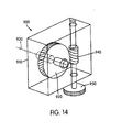
- FIG. 14 illustrates a manual selectively-operable driving mechanism in which a manually-rotatable head replaces the electric motors in the previous embodiments.
- a gearbox 900 comprises a housing 910, a worm wheel 920 pivotally connected to the housing 910 for rotation about a worm wheel axis 930, a worm gear 940 pivotally connected to the housing 910 and meshing with the worm wheel 920, and a manually-rotatable head in the form of a hand-operated control wheel 950 operatively connected to the worm gear 940.
- the worm wheel 920 may be operatively, rotationally, coupled to any of the previously described running board assemblies.
- the gearbox 900 may replace the gearbox 46 of the retractable running board assembly 20 illustrated in FIG. 2 , in which case the worm wheel 920 would be operatively connected to the torque member 50.
- an operator may use his/her hands to rotate the control wheel 950, which rotates the worm gear 940.
- Rotation of the worm gear 940 rotates the worm wheel 920, which rotates the torque member 50 and actuates the retractable running board assembly 20.
- the worm wheel 920 and gear 940 prevent backdrive of the gearbox 900 and attached torque member 50 and running board assembly 20.
- FIG. 15 illustrates a possible modification to the gearbox 900 illustrated in FIG. 14 .
- This remotely, manually-operated gearbox 1000 is very similar to the gearbox 900, except that a control wheel 1010 of the gearbox 1000 is remotely located.
- the control wheel 1010 is operatively connected to a worm gear 1020 via a flexible torque cable 1030 that is similar to the cables described above with respect to previous embodiments.
- the flexible torque cable allows the control wheel 1010 to be mounted in any convenient position in a vehicle.
- the control wheel may be mounted within the cab of a truck so that an operator can manually operate the retractable running board assembly without having to first exit the vehicle to gain access to the control wheel.
- FIG. 16 illustrates a further possible modification to the gearbox 900.
- a gearbox 1100 is similar to the gearbox 900 except that the manually-rotatable head comprises a hex head 1110 instead of a control wheel 950 as is utilized by the gearbox 900.
- the hex head 1110 is preferably sized to match a jack tool, lug wrench, or other tool that is typically kept in the associated vehicle.
- an operator connects the tool to the hex head 1110 and rotates the tool to rotate the hex head 1110 and actuate the associated retractable running board assembly.
- FIG. 17 illustrates a further manually-rotatable head in the form of a hollow receiver 1200 that may replace the hex head 1110 in the gearbox 1100.
- the hollow receiver 1200 may be rotated using a drive blade such as a large flat-head screwdriver or the prying end of a jack tool.
- a variety of alternatively shaped pieces may replace the above described control wheel 950, hex head 1110, or hollow receiver 1200.
- the manual driving mechanisms shown in FIGS. 14-17 for manually driving the torque transmitting member may be provided in addition to or in lieu of an electric motor. Specifically, if the vehicle loses power, the operator can bypass the motor and manually drive the torque transmitting via the manual driving mechanism to manually actuate the running board.
Landscapes
- Engineering & Computer Science (AREA)
- Mechanical Engineering (AREA)
- Vehicle Step Arrangements And Article Storage (AREA)
- Lock And Its Accessories (AREA)
Abstract
Description
- The present invention relates to a retractable running board assembly for use with a vehicle.
- Most conventional vehicle running boards have fixed positions relative to the frames of the vehicles that they are attached to.
- Designers of fixed-position running board vehicles must balance ground clearance against the desire to place running boards in a lower, more passenger convenient position midway between ground level and the lower edge of the vehicle door opening. In a vehicle such as a truck, in which a large ground clearance is advantageous, the cab and passenger seats are typically disposed well above ground level. Consequently, conventional running boards provide an intermediate step for passengers to use to enter and exit the vehicle. From the standpoint of facilitating a passenger's entrance and exit from the vehicle, the most convenient height for a running board is generally at about half the distance between the ground level and the lower edge of the vehicle door opening. However, disposing the running board at such a low position reduces the vehicle's ground clearance. Consequently, designers must sacrifice either convenience or ground clearance when determining the height of a fixed-position running board.
- The generic
US-A-5,697,626 describes running boards with selectively variable heights. When the vehicle is being driven, the running board is raised vertically to improve the vehicle's ground clearance. Conversely, when the vehicle is stopped, the running board can be lowered to position the running board at a more convenient height for the passengers. - Vehicle designers face an additional dilemma when determining the lateral position of fixed-position running boards. To provide the most convenience to passengers entering or exiting a vehicle, the running board should be disposed laterally outwardly from the vehicle's entrances/doors such that the lower edge of the door opening, the running board, and the ground form laterally- and vertically-spaced steps like those in building stairways. Unfortunately, disposing a running board fixed laterally outwardly from the vehicle for the passengers' convenience disadvantageously increases the vehicle's width.
-
US-A-3,608,957 describes a running board designed to extend laterally outwardly when the vehicle's door is opened such that the running board is in a convenient laterally-outward position when the passengers need to use it to enter and exit the vehicle. Conversely, the running board is retracted laterally inwardly when the door is closed so that the vehicle has a narrower width during operation. - The applicants are aware of a retractable running board developed by Amp Research of Irvine, California that moves both laterally and vertically between its extended and retracted positions. It is believed that two longitudinally spaced four-bar linkages connect the running board to the vehicle, and that an automatic actuator powers only one of the two linkages to extend the running board downwardly and outwardly when the vehicle's passenger door is opened. The second four-bar linkage is believed to move freely and therefore follows the movements of the first powered linkage as the powered movement of the first linkage is transferred through the length of the running board to the second linkage. Because the second linkage is not, itself, powered and cannot resist movement of the running board, the running board cannot be firmly held in place, especially when the weight of a passenger is exerted on the running board at a position far from the first powered linkage.
- The not prepublished
WO-A-02/053416 - The not prepublished
WO-A-02/085670 - The present invention seeks to provide a running board assembly having a backdrive prevention mechanism.
- According to the present invention, there is provided a retractable running board assembly for use with a vehicle having a passenger compartment and a door opening providing access to the passenger compartment, the assembly comprising:
- an anchor constructed and arranged to mount the running board assembly to the vehicle in an operative position beneath the door opening;
- an elongated retractable running board having a non-circular cross-section perpendicular to a longitudinal direction thereof; and
- a running board moving assembly comprising:
- at least one selectively-actuated link connected between the running board and the anchor and movably supporting the running board, the link being constructed and arranged such that, when the running board assembly is mounted to the vehicle in the operative position, actuation of the link moves the running board in an arcuate path in extending and retracting directions between (a) an extended position wherein the running board is extended outwardly from the vehicle away from the door opening at an elevation lower than the door opening and spaced above ground level for facilitating entry into the passenger compartment via the door opening and (b) a retracted position wherein the running board is retracted inwardly and raised upwardly from the extended position, the extending and retracting directions having both vertical and horizontal components, the link enabling the running board to maintain substantially the same orientation during movement between the extended and retracted positions; and
- a selectively-operable driving mechanism comprising a transmission having (a) a worm gear to which driving force is applied, and (b) a worm wheel meshed with the worm gear and operatively connected to the link such that, when the running board assembly is mounted in the operative position, selective operation of the driving mechanism rotates the worm wheel to actuate the link to move the running board between the retracted and extended positions;
- wherein rotation of the worm gear by the driving force in one direction rotates the worm wheel to move the running board in the extending direction to the extended position, and in the other direction rotates the worm wheel to move the running board in the retracting direction to the retracted position; and
- wherein the meshing between the worm gear and the worm wheel prevents a downward force applied to the running board from rotating the worm wheel, thus limiting the running board from being moved by the downward force,
- wherein the at least one selectively-actuated link includes at least first and second selectively-actuated links movably supporting the running board at longitudinally spaced apart positions,
- wherein the first and second selectively-actuated links each comprise a four-bar mechanism comprising:
- a first leg defined by the anchor;
- a second leg connected to the first leg for pivotal movement about a longitudinal axis relative to the first leg;
- a third leg pivotally connected to the first leg; and
- a fourth leg pivotally connected to the second and third legs, the running board being mounted to the fourth leg, and
- wherein the running board moving assembly further comprises an elongated torque transmitting member operatively connecting each of the second legs of the first and second selectively-actuated links to the worm wheel of the selectively-operable driving mechanism's transmission to transmit torque from the selectively-operable driving mechanism to pivot the second legs about the longitudinal axis, thus causing the links to move the running board between the extended and retracted positions.
- The worm gear and worm wheel provide a backdrive prevention mechanism.
- With a board of circular cross-section, its orientation is not material, as it will provide the same configuration for stepping thereupon irrespective of its orientation. However, with a board of non-circular cross-section, as in embodiments of the invention, maintaining its orientation the same between its extended and retracted positions, and any other positions, is advantageous. Specifically, even when the board is fully retracted, persons may still step on it and it is desirable to keep it properly oriented for this reason. Also, if the board has multiple extended positions, it is desirable to maintain the same orientations between positions.
- In an embodiment, the worm wheel of the selectively-operable driving mechanism's transmission is operatively connected to each of the first and second selectively actuated links such that, when the running board assembly is mounted in the operative position, selective operation of the driving mechanism rotates the worm wheel to actuate each of the selectively actuated links to move the running board between the retracted and extended positions.
- Preferably, the at least one selectively-actuated link is constructed and arranged such that, when the running board assembly is mounted to the vehicle in the operative position, actuation of the link moves the running board between (a) the retracted position, (b) the extended position, and (c) a secondary extended position wherein the running board is moved upwardly from the primary extended position for facilitating passenger access to a roof of the vehicle.
- In an embodiment, the vehicle includes an additional door opening and the running board assembly further comprises an additional elongated retractable running board having a non-circular cross-section perpendicular to a longitudinal direction thereof;
wherein the running board moving assembly further comprises at least one additional selectively-actuated link connected between the additional running board and the anchor and movably supporting the additional running board, the link being constructed and arranged such that, when the running board assembly is mounted to the vehicle in the operative position, actuation of the additional link moves the additional running board in extending and retracting directions between (a) a retracted position, (b) an extended position wherein the running board is moved at least outwardly with respect to the vehicle from the retracted position for facilitating passenger entry into the passenger compartment via the additional door opening, the extending and retracting directions of the additional running board having both vertical and horizontal components, the additional link enabling the additional running board to maintain essentially the same orientation during movement between the extended and retracted position; and
wherein the selectively-operable driving mechanism further comprises a second transmission having (a) a worm gear to which a driving force is applied, and (b) a worm wheel meshed with the worm gear and operatively connected to the additional link such that, when the running board assembly is mounted in the operative position, selective operation of the driving mechanism actuates the additional link to move the additional running board between the retracted and extended positions;
wherein rotation of the second transmission's worm gear by the driving force in one direction rotates the worm wheel to move the additional running board in the extending direction to the extended position, and in the other direction rotates the worm wheel to move the additional running board in the retracting direction to the retracted position;
wherein the meshing between the worm gear and the worm wheel of the second transmission prevents a downward force applied to the additional running board from rotating the worm wheel, thus limiting the additional running board from being moved by the downward force. - Embodiments of the present invention will hereinafter be described, by way of example, with reference to the accompanying drawings, in which:
-
FIG. 1 is a perspective view of a truck with a retractable running board assembly of the invention, showing the running board in an extended position; -
FIG. 2 is a partial perspective view of the running board ofFIG. 1 in the extended position; -
FIG. 3 is a partial perspective view of the running board ofFIG. 1 in a retracted position; -
FIG. 4 is a partial perspective view of a second, embodiment of a retractable running board; -
FIG. 5 is a partial perspective view of a further embodiment of a running board; -
FIG. 6 is a front view of an alternative arrangement of a running board which is not an embodiment of the invention; -
FIG. 7 is a front view of a further alternative arrangement of a running board which is not an embodiment of the invention; -
FIGS. 8A and 8B are partial perspective views showing a further embodiment of a running board; -
FIG. 9 is a partial sectional view of the embodiment illustrated inFIGS. 8A and 8B , taken along theline 8C-8C inFIG. 8A . -
FIGS. 10 and11 are perspective views of a further embodiment of a running board; -
FIGS. 12 and13 are perspective views of a further embodiment of a running board; -
FIGS. 14 to 16 are perspective views of manual gearboxes for a running board assembly; and -
FIG. 17 is a partial perspective view of a manual gearbox. -
FIG. 1 illustrates avehicle 10 that has a retractablerunning board assembly 20 according to an embodiment of the invention. The retractablerunning board assembly 20 includes ananchor 24 mounted to a frame (or body) 25 of thevehicle 10 in an operative position below a passenger compartment of thevehicle 10. Thevehicle 10 has a longitudinal direction that is defined by the direction of movement of thevehicle 10. While the runningboard assembly 20 in this embodiment is disposed along the passenger side of thevehicle 10, the runningboard assembly 20 may alternatively be disposed along a variety of other portions of thevehicle 10 such as the driver's side, the front, or the back. Further, the retractablerunning board assembly 20 may also be utilized in other types of vehicles, such as construction equipment or sport utility vehicles. - While the
anchor 24 and theframe 25 are illustrated as distinct elements, the anchor may be an integral part of the frame/body. The term anchor is a structural term used herein to encompass any structure mounting theassembly 20 to thevehicle 10. -
FIG. 2 is an enlarged perspective view of the retractablerunning board assembly 20. A longitudinally elongatedretractable running board 26 is connected to theanchor 24 via a runningboard moving assembly 27. Theboard 26 has a non-circular cross-section perpendicular to its longitudinal direction. As illustrated, it is somewhat Z-shaped in cross-section. The runningboard moving assembly 27 includes a plurality of longitudinally spaced selectively-actuatedlinks board 26 is generally parallel to a longitudinal direction of thevehicle 10. However, if the runningboard assembly 20 were disposed on thevehicle 10 in a position other than along the lateral sides, the runningboard 26 would not parallel the longitudinal direction of thevehicle 10. - The running board moving assembly also includes a selectively-operable driving mechanism that is operatively connected to each of the plurality of selectively-actuated
links links board 26 between an extended position (as shown inFIGS. 1 and2 ) and a retracted position (as shown inFIG. 3 ). The driving mechanism may be of any type, including a D.C. reversible electric motor, a fluid driven motor, or a manually operated input, such as a lever, a crank, a wheel, or a rotatable lug. - As best illustrated in
FIG. 2 , each of thelinks anchor 24. Asecond leg 36 connects to the first leg/anchor 24 for pivotal movement about alongitudinal axis 38 relative to the first leg/anchor 24. Thelongitudinal axis 38 is generally parallel to the longitudinal direction of the runningboard 26. Athird leg 40 also pivotally connects to the first leg/anchor 24. Afourth leg 42 pivotally connects to the second andthird legs board 26. Thefourth leg 42 is preferably elongated so as to provide structural support to the runningboard 26. - Actuation of the
links board 26 along a generally arcuate or curved path that is generally perpendicular to thelongitudinal axis 38. Depending on the relative lengths of thelegs board 26 may also include a rotational component. Each four-bar mechanism comprises a parallelogram such that the path of the runningboard 26 has no rotational component and the runningboard 26 is always generally level. The runningboard 26 therefore moves downwardly and outwardly relative to thevehicle 10 andanchor 24 as it moves from its retracted position to its extended position. When in the extended position, the runningboard 26 is preferably disposed (a) at a height generally midway between ground level and alower edge 43a of an adjoining door opening 43 of thevehicle 10 and (b) at a lateral position that is disposed at least partially outward from a side of thevehicle 10 in order to facilitate easy entrance into and exit from thevehicle 10. When thevehicle 10 is on level ground with the runningboard 26 in the extended position, the runningboard assembly 20 does not touch the ground. - The extended and retracted positions of the running
board 26 are both vertically and horizontally offset from each other. However, the path of the running board may comprise one or more of horizontal movement, vertical movement, and rotational components. - The four-bar mechanisms used as the
links platform 44 defined by a top surface of the runningboard 26 is generally level when the runningboard 26 is in the extended position. Thelinks board 26 as close to thevehicle 10 as possible when the runningboard 26 is in the retracted position. - The running
board moving assembly 27 includes a longitudinally elongatedtorque transmitting member 50 that is mounted to each of thesecond legs 36 of thelinks second legs 36 about thelongitudinal axis 38, which is generally parallel to the longitudinal direction of the runningboard 26. Thetorque transmitting member 50 may be rotationally coupled to each of thesecond legs 36 using any appropriate method. For example, thetorque transmitting member 50 may have a square cross-section that fits into square holes in thesecond legs 36. Alternatively, a spline and keyway may be used to rotationally couple thetorque transmitting member 50 to each of thesecond legs 36. Thetorque transmitting member 50 could also be welded to or formed integrally with thesecond legs 36. - The
torque transmitting member 50 is operatively connected to themotor 34 via agear box 46. Thegearbox 46 operates as a step-down mechanism such that thetorque transmitting member 50 rotates substantially slower than themotor 34. Thegear box 46 includes a worm gear operatively connected to themotor 34 and a worm wheel operatively connected to thetorque transmitting member 50. The worm gear and wheel serve dual functions by stepping down the speed of the motor 34 (and stepping up the torque) and locking thetorque transmitting member 50 andgear box 46 into fixed rotational positions when themotor 34 is not being operated. The pitch of a worm gear and wheel creates a frictional resistance that prevents a rotational force acting upon the worm wheel from rotating the worm gear (i.e., backdrive). Consequently, when themotor 34 is not being operated, thetorque transmitting member 50,links board 26 are locked into fixed positions, and hence the worm wheel and worm gear may be considered a backdrive prevention mechanism. Because each of thelinks board 26 is substantially immovable relative to theanchor 24 even when the weight of a passenger is exerted on a longitudinal end of the runningboard 26. - In the illustrated embodiment, the selectively-
operable motor 34 is an electric motor that is operated with a conventional electrical control circuit. If the control circuit is automatically controlled, the circuit could selectively operate themotor 34 to extend the running board into its extended position when thevehicle 10 is placed in park, when the doors are opened, or when the ignition is turned off. Alternatively, if the control circuit is manually controlled, an operation switch could be placed within the cab of the truck to allow an operator to selectively control the extension position of the runningboard 26. - Whilst the illustrated
motor 34 is an electric rotational motor, other types of motors could be utilised. For example, themotor 34 may be a linear motor, a hydraulic motor, a hydraulic cylinder, or a linear actuator. -
FIG. 4 illustrates an alternative embodiment of a retractablerunning board assembly 58, in which only two selectively-actuatedlinks FIGS. 1 to 3 , two shorttorque transmitting members second legs 36 of thelinks Worm wheels 66 are rotationally coupled to each of thetorque transmitting members worm wheels 66. Each of the worm gears 68 is operatively connected to amotor 70 via a flexibletorque transmitting cable 72 and agear box 74. The flexibletorque transmitting cable 72 preferably comprises a rotating inner cable mounted within an outer sheath. Each inner cable is operatively connected to aworm gear 68 and thegear box 74 in a conventional manner. As previously, the worm gears 68 andwheels 66 prevent thelinks motor 70 is not being operated. When themotor 70 is operated, the links are concertedly actuated to extend and retract the runningboard 26. Because flexibletorque transmitting cables 72 connect themotor 70 to thelinks 28, 32 (as opposed to the rigid connection of the previous embodiment), themotor 70 may be mounted in any convenient position on thevehicle 10. -
FIG. 5 is a perspective view of an additional embodiment in which two retractablerunning board assemblies board assembly 20 illustrated inFIGS. 1-3 , are provided The runningboard assembly 80 is preferably mounted to a vehicle below passenger doors on one lateral side of the vehicle while the runningboard assembly 82 is preferably mounted below passenger doors on an opposite lateral side of the vehicle. Consequently,retractable running boards - The
anchor 84 of the runningboard assemblies vehicle 10 below the passenger doors located on either lateral side of thevehicle 10. Theanchor 84 may comprise a plurality of independent portions or a single integral piece. In the embodiment illustrated inFIG. 5 , theanchor 84 comprises a plurality of independent pieces that are each arranged to be mounted on avehicle 10. - Unlike the embodiment illustrated in
FIGS. 1-3 , however, themotor 100 ofFIG. 5 is not directly geared to the longitudinally elongatedtorque transmitting members motor 100 is operatively connected to agearbox 106, which, in turn, is operatively connected to flexibletorque transmitting cables torque transmitting cables torque tubes torque transmitting members links links FIGS. 1-3 .Running boards links motor 100 may be disposed at any convenient position on a vehicle. - This embodiment may also include just one running
board assembly 102. -
FIG. 6 illustrates an additional arrangement of a retractablerunning board assembly 200 which is not an embodiment of the invention. The runningboard assembly 200 is generally similar to the runningboard assembly 20 except that the selectively-actuated links 202, 204, 206 comprise cam slides and linear actuators instead of four-bar mechanisms. - Each of the links 202, 204, 206 comprises a
cam track 210 rigidly mounted to ananchor 212, which is, in turn, rigidly mounted to aframe 213 of a vehicle. A plurality ofcam sliders 214 are mounted to a longitudinally elongated runningboard 216, which also has a non-circular cross-section, and are supported by thecam track 210 so as to allow thecam sliders 214 to move freely along thetrack 210 between an extended position (as shown inFIG. 6 ) and a retracted position (position in whichcam sliders 214 are shown in phantom inFIG. 6 ). At each link 202, 204, 206, a conventional lead-screw linear actuator 218 connects theanchor 212 to the runningboard 216. The linear actuator 218 preferably includes a threadednut 220 pivotally mounted to the runningboard 216. A lead screw 222 is threaded into thenut 220. Abase 224 of the linear actuator 218 is pivotally connected to theanchor 212 for relative rotation therebetween about alongitudinal axis 225. Thebase 224 supports the lead screw 222 so as to prevent relative movement (e.g., backdrive) between the lead screw 222 and thebase 224 along alead screw axis 226 while allowing relative rotation between the lead screw 222 and the base 224 about thelead screw axis 226. Aworm wheel 230 is mounted to the lead screw 222 for common rotation about thelead screw axis 226. - A longitudinally elongated
torque transmitting member 232, which is generally identical to thetorque transmitting member 50 of the runningboard assembly 20, is mounted for rotation relative to theanchor 212 about thelongitudinal axis 225. A motor is operatively connected to thetorque transmitting member 225 in the same fashion as themotor 34 is connected to thetorque transmitting member 50 in the runningboard assembly 20 illustrated inFIGS. 1-3 . At each link 202, 204, 206, aworm gear 234 is mounted onto thetorque transmitting member 232 for common rotation therewith about thelongitudinal axis 225. Theworm gear 234 meshes with theworm wheel 230 such that rotation of thetorque transmitting member 232 actuates the lead screw actuator 218 to extend or retract the runningboard 216 along thecam slide 210 with the runningboard 216 maintaining essentially the same orientation between its extended and retracted positions. - The
torque transmitting member 232 may have a rotational displacement that is greater than or less than 360 degrees. The term, rotation, is therefore intended to encompass angular displacements greater than or less than 360 degrees. In this embodiment, the rotational displacement of the torque transmitting member is preferably greater than 360 degrees. However, in the previous embodiments that include four-bar mechanisms, the rotational displacements of thetorque transmitting members - Instead of mounting the
cam track 210 to the anchor and thecam sliders 214 to the runningboard 216, thecam track 210 could be conversely rigidly mounted to the runningboard 216 and thecam sliders 214 could be mounted to the anchor. - In the arrangement illustrated in
FIG. 6 , thecam track 210 forms a slight "S" shape, but thecam track 210 could also be shaped in a variety of other ways. For exampleFIG. 7 illustrates an additional alternative arrangement, which is generally similar to the previous one, except that thecam track 310 is linear. -
FIGS. 8A and 8B , and9 illustrate an additional embodiment of a retractablerunning board assembly 500, which is generally identical to the retractablerunning board assembly 58 illustrated inFIG. 4 and discussed above. The retractablerunning board assembly 500 inFIGS. 8A and 8B differs from the retractablerunning board assembly 58 in the following respects. - As illustrated in
FIG. 8A andFIG. 9 , the retractablerunning board assembly 500 includes a runningboard 510 that replaces/defines the sill of thevehicle 520. When the retractablerunning board assembly 500 is in the retracted position (as illustrated inFIGS. 8A and9 ), anupper edge 525 of an outerlateral surface 530 of the runningboard 510 abuts alower edge 560 of an outerlateral surface 540 of aside panel 544 of thevehicle 520. When theretractable running board 500 is in the retracted position, thesurfaces surfaces surfaces surfaces surfaces - As illustrated in
FIG. 9 , when theretractable running board 510 is in the retracted position, anupper surface 550 of theretractable running board 510 abuts alower surface 565 of theside panel 544. As illustrated inFIG. 8B , when the retractablerunning board assembly 500 is extended, the retractablerunning board assembly 500 functions in the same manner and is positioned in the same general location as the retractablerunning board assembly 58. The other illustrated retractable running board assemblies may also be modified in a similar manner to replace the sill of the vehicle. -
FIGS. 10 and11 illustrate an alternative embodiment of a retractablerunning board assembly 700. As in the previous embodiments, a longitudinally elongatedretractable running board 702 is connected to ananchor 704 via a plurality of longitudinally spaced, selectively-actuatedlinks operable motor 730 is operatively connected to each of thelinks motor 730 concertedly actuates each of thelinks board 702 between an extended position (as shown inFIG. 11 ) and a retracted position (as shown inFIG. 10 ). - As illustrated in
FIG. 10 , each of thelinks anchor 704. Asecond leg 740 connects to the first leg/anchor 704 for pivotal movement about a generally vertical axis 742. Athird leg 750 also pivotally connects to the first leg/anchor 704. Afourth leg 760 pivotally connects to the second andthird legs board 702. In this embodiment, the runningboard 702 andfourth legs 760 are integrally formed. However, the runningboard 702 andfourth legs 760 may also be separately formed. - The four-bar mechanisms defined by the
links board assembly 700, thefourth legs 760 remain parallel to theanchor 704. - The lengths of each of the
legs link 710 are preferably equal to the lengths of the correspondinglegs link 720. Consequently, during concerted actuation of thelinks fourth legs 760 is synchronous and prevents the runningboard 702 from rotating relative to theanchor 704. - Because the pivotal axes of the
links board 702 relative to theanchor 704 is substantially limited to a horizontal path (+/- several vertical inches and preferably +/- 3 vertical inches). During extension and retraction of the runningboard assembly 700, the running board translationally follows a curved path defined by thelinks board 702 is disposed at a substantially constant height regardless of its extension position. As illustrated inFIGS. 10 and11 , the runningboard 702 moves laterally-outwardly relative to theanchor 704 as it extends from its retracted position to its extended position. - The
motor 730 is operatively connected to thelinks torque transmitting member 770. Thetorque transmitting member 770 may be directly rotationally mounted to themotor 730 or may be operatively connected to themotor 730 via a gear drive system that either steps up or steps down the speed of thetorque transmitting member 770 relative to themotor 730. - In the illustrated embodiment, the
torque transmitting member 770 is operatively connected to thesecond legs 740 of thelinks torque transmitting member 770 and alink worm gear 780 mounted onto thetorque transmitting member 770. Whileseparate worm gears 780 are illustrated, theseparate worm gears 780 may alternatively each comprise a part of a single extended worm gear. The worm gear drive also includes aworm wheel 790 that meshes with theworm gear 780 and is mounted to thesecond leg 740 for common rotational movement relative to theanchor 704 about the axis 742. During extension or retraction of the runningboard assembly 700, themotor 730 rotates thetorque transmitting member 770, which, in turn, concertedly actuates thesecond legs 740 of thelinks second legs 740 actuates thelinks board 702. - As in the previous embodiments, because the worm gear drives prevent backdrive of the
links board assembly 700 remains in an essentially locked position unless actuated by themotor 730. - As in the previous embodiments, the
anchor 704 may form or be attached to any desired part on a vehicle. - While the above-described embodiments include either two or three powered links attaching each running board to each anchor, more or less powered links may be provided. Further, additional freely moving links may also be provided. For example,
FIGS. 12 and13 illustrate an additional embodiment of a retractablerunning board assembly 800 which is generally identical to the runningboard assembly 700 illustrated inFIGS. 10 and11 except that only one of the twolinks second leg 840 of the selectively-actuatedlink 820 is operatively connected to amotor 850, via a worm gear drive and/or other gear reduction mechanisms. Consequently, thelink 820 is selectively actuated by themotor 850. Conversely, thefree link 810 is not directly operatively connected to themotor 850 and simply follows the movement of thelink 820 as forces are transferred from thelink 820, through the runningboard 860, to thelink 810. - The running
board assembly 800 can use just a singlepowered link 820 because, as is analogously discussed above with respect to the retractablerunning board assembly 700, the limited horizontal path of the runningboard 860 ensures that significant backdrive creating forces are not applied to thelinks motor 850. Onepowered link 820 is therefore sufficient to hold the runningboard 860 stationary. - While the selectively-operable driving mechanism in the previous embodiments comprises an electric motor such as the
motor 34 illustrated inFIG. 2 , the selectively operable driving mechanism according to the present invention encompasses a variety of other actuators, both automatic and manual, as well. Such selectively-operable driving mechanisms include hydraulic or air motors, linear actuators, or hydraulic cylinders. For example,FIG. 14 illustrates a manual selectively-operable driving mechanism in which a manually-rotatable head replaces the electric motors in the previous embodiments. Agearbox 900 comprises ahousing 910, aworm wheel 920 pivotally connected to thehousing 910 for rotation about aworm wheel axis 930, aworm gear 940 pivotally connected to thehousing 910 and meshing with theworm wheel 920, and a manually-rotatable head in the form of a hand-operatedcontrol wheel 950 operatively connected to theworm gear 940. - The
worm wheel 920 may be operatively, rotationally, coupled to any of the previously described running board assemblies. For example, thegearbox 900 may replace thegearbox 46 of the retractablerunning board assembly 20 illustrated inFIG. 2 , in which case theworm wheel 920 would be operatively connected to thetorque member 50. To use the manually operatedgearbox 900, an operator may use his/her hands to rotate thecontrol wheel 950, which rotates theworm gear 940. Rotation of theworm gear 940 rotates theworm wheel 920, which rotates thetorque member 50 and actuates the retractablerunning board assembly 20. As described above, theworm wheel 920 andgear 940 prevent backdrive of thegearbox 900 and attachedtorque member 50 and runningboard assembly 20. -
FIG. 15 illustrates a possible modification to thegearbox 900 illustrated inFIG. 14 . This remotely, manually-operatedgearbox 1000 is very similar to thegearbox 900, except that acontrol wheel 1010 of thegearbox 1000 is remotely located. Accordingly, thecontrol wheel 1010 is operatively connected to aworm gear 1020 via aflexible torque cable 1030 that is similar to the cables described above with respect to previous embodiments. The flexible torque cable allows thecontrol wheel 1010 to be mounted in any convenient position in a vehicle. For example, the control wheel may be mounted within the cab of a truck so that an operator can manually operate the retractable running board assembly without having to first exit the vehicle to gain access to the control wheel. -
FIG. 16 illustrates a further possible modification to thegearbox 900. Agearbox 1100 is similar to thegearbox 900 except that the manually-rotatable head comprises ahex head 1110 instead of acontrol wheel 950 as is utilized by thegearbox 900. Thehex head 1110 is preferably sized to match a jack tool, lug wrench, or other tool that is typically kept in the associated vehicle. To operate thegearbox 1100, an operator connects the tool to thehex head 1110 and rotates the tool to rotate thehex head 1110 and actuate the associated retractable running board assembly. -
FIG. 17 illustrates a further manually-rotatable head in the form of ahollow receiver 1200 that may replace thehex head 1110 in thegearbox 1100. Thehollow receiver 1200 may be rotated using a drive blade such as a large flat-head screwdriver or the prying end of a jack tool. A variety of alternatively shaped pieces may replace the above describedcontrol wheel 950,hex head 1110, orhollow receiver 1200. - The manual driving mechanisms shown in
FIGS. 14-17 for manually driving the torque transmitting member may be provided in addition to or in lieu of an electric motor. Specifically, if the vehicle loses power, the operator can bypass the motor and manually drive the torque transmitting via the manual driving mechanism to manually actuate the running board.
Claims (14)
- A retractable running board assembly (20; 58; 80, 82; 200; 500; 700; 800; 1300) for use with a vehicle (10; 520) having a passenger compartment and a door opening providing access to the passenger compartment, the assembly comprising:an anchor (24; 84; 212; 704; 1304) constructed and arranged to mount the running board assembly to the vehicle in an operative position beneath the door opening;an elongated retractable running board (26; 124; 126; 216; 510; 702; 860; 1302) having a non-circular cross-section perpendicular to a longitudinal direction thereof; anda running board moving assembly (27, 1306) comprising:at least one selectively-actuated link (28, 30, 32; 112, 114, 116, 118; 202, 204, 206; 710, 720; 810, 820; 1308, 1310) connected between the running board and the anchor and movably supporting the running board, the link being constructed and arranged such that, when the running board assembly is mounted to the vehicle in the operative position, actuation of the link moves the running board in an arcuate path in extending and retracting directions between a) an extended position wherein the running board is extended outwardly from the vehicle away from the door opening at an elevation lower than the door opening and spaced above ground level for facilitating entry into the passenger compartment via the door opening and b) a retracted position wherein the running board is retracted inwardly and raised upwardly from the extended position, the extending and retracting directions having both vertical and horizontal components, the link enabling the running board to maintain substantially the same orientation during movement between the extended and retracted positions; and characterized in thata selectively-operable driving mechanism (34; 70; 100; 730; 850; 950; 1312) comprising a transmission (50; 60, 62; 102, 104; 232; 770; 1328) having a) a worm gear (68; 234; 780; 940) to which driving force is applied, and b) a worm wheel (66; 230; 790; 920) meshed with the worm gear and operatively connected to the link such that, when the running board assembly is mounted in the operative position, selective operation of the driving mechanism rotates the worm wheel to actuate the link to move the running board between the retracted and extended positions;wherein rotation of the worm gear by the driving force in one direction rotates the worm wheel to move the running board in the extending direction to the extended position, and in the other direction rotates the worm wheel to move the running board in the retracting direction to the retracted position; andwherein the meshing between the worm gear and the worm wheel prevents a downward force applied to the running board from rotating the worm wheel, thus limiting the running board from being moved by the downward force,wherein the at least one selectively-actuated link (28, 30, 32; 112, 114, 116, 118; 202, 204, 206; 710, 720; 810, 820; 1308, 1310) includes at least first and second selectively-actuated links movably supporting the running board (26; 124, 126; 216; 510; 702; 860; 1302) at longitudinally spaced apart positions,wherein the first and second selectively-actuated links (28, 30, 32; 710, 720; 1308, 1310) each comprise a four-bar mechanism comprising:a first leg defined by the anchor (24; 704; 1304);a second leg (36; 740; 1316) connected to the first leg for pivotal movement about a longitudinal axis relative to the first leg;a third leg (40; 750; 1320) pivotally connected to the first leg; anda fourth leg (42; 760; 1324) pivotally connected to the second and third legs, the running board (26; 702; 1302) being mounted to the fourth leg, andwherein the running board moving assembly (27; 1306) further comprises an elongated torque transmitting member (50; 770; 1328) operatively connecting each of the second legs (36; 740; 1316) of the first and second selectively-actuated links to the worm wheel (66; 790) of the selectively-operable driving mechanism's transmission to transmit torque from the selectively-operable driving mechanism to pivot the second legs about the longitudinal axis, thus causing the links to move the running board between the extended and retracted positions.
- A retractable running board assembly as claimed in Claim 1, wherein the worm wheel (66; 230; 790; 920) of the selectively-operable driving mechanism's transmission is operatively connected to each of the first and second selectively-actuated links (28, 30, 32; 710, 720; 1308, 1310) such that, when the running board assembly is mounted in the operative position, selective operation of the driving mechanism rotates the worm wheel to actuate each of the selectively actuated links to move the running board between the retracted and extended positions.
- A retractable running board assembly as claimed in Claim 1 or Claim 2, wherein the at least one selectively-actuated link (28, 30, 32; 112, 114, 116, 118; 202, 204, 206; 710, 720; 810, 820; 1308, 1310) is constructed and arranged such that, when the running board assembly is mounted to the vehicle in the operative position, actuation of the link moves the running board between (a) the retracted position, (b) the extended position, and (c) a secondary extended position wherein the running board is moved upwardly from the primary extended position for facilitating passenger access to a roof of the vehicle.
- A retractable running board assembly as claimed in any preceding claim, wherein the vehicle (10; 520) includes an additional door opening and the running board assembly (80; 82) further comprises an additional elongated retractable running board (124; 126) having a non-circular cross-section perpendicular to a longitudinal direction thereof;
wherein the running board moving assembly (27) further comprises at least one additional selectively-actuated link (112; 114; 116; 118; 120; 122) connected between the additional running board and the anchor and movably supporting the additional running board, the link being constructed and arranged such that, when the running board assembly is mounted to the vehicle in the operative position, actuation of the additional link moves the additional running board in extending and retracting directions between (a) a retracted position, (b) an extended position wherein the running board is moved at least outwardly with respect to the vehicle from the retracted position for facilitating passenger entry into the passenger compartment via the additional door opening, the extending and retracting directions of the additional running board having both vertical and horizontal components, the additional link enabling the additional running board to maintain essentially the same orientation during movement between the extended and retracted position; and
wherein the selectively-operable driving mechanism (100) further comprises a second transmission (102, 104) having (a) a worm gear to which a driving force is applied, and (b) a worm wheel meshed with the worm gear and operatively connected to the additional link such that, when the running board assembly is mounted in the operative position, selective operation of the driving mechanism actuates the additional link to move additional running board between the retracted and extended positions;
wherein rotation of the second transmission's worm gear by the driving force in one direction rotates the worm wheel to move the additional running board in the extending direction to the extended position, and in the other direction rotates the worm wheel to move the additional running board in the retracting direction to the retracted position;
wherein the meshing between the worm gear and the worm wheel of the second transmission prevents a downward force applied to the additional running board from rotating the worm wheel, thus limiting the additional running board from being moved by the downward force. - A retractable running board assembly as claimed in Claim 4, wherein the at least one link (112; 114; 116; 118; 120; 122) includes first and second selectively-actuated links connected to the anchor and movably supporting the running board at longitudinally spaced positions and the at least one additional link includes third and fourth selectively-actuated links connected to the anchor and movably supporting the additional running board at longitudinally spaced apart positions.
- A retractable running board assembly as claimed in Claim 5, wherein the running board moving assembly further comprises:a first elongated torque transmitting member (102) operatively connecting each of the first and second selectively-actuated links (112; 114; 116) to the worm wheel of the transmission; anda second elongated torque transmitting member (104) operatively connecting each of the third and fourth selectively-actuated links (118, 120, 122) to the worm wheel of the transmission,wherein operation of the selectively-operable driving mechanism rotates worm wheels to rotate the first and second torque transmitting members to concertedly actuate each of the links and move the running boards between the respective extended and retracted positions.
- A retractable running board assembly as claimed in Claim 6, wherein the running board moving assembly further comprises:first and second flexible torque transmitting cables (108, 110) operatively connected to each of the worm gears for transmitting driving force to the worm gears.
- A retractable running board assembly as claimed in Claim 1, wherein the at least one selectively-actuated link (28, 30, 32; 112, 114, 116, 118; 202, 204, 206; 710, 720; 810, 820; 1308, 1310) is constructed and arranged such that the running board moves in an arcuate path between the extended and retracted positions.
- A retractable running board assembly as claimed in Claim 8, wherein the running board (26; 124, 126; 216; 510; 702; 860; 1302) has a non-circular cross-section perpendicular to a longitudinal direction thereof and
wherein the at least one selectively-actuated link (28, 30, 32; 112, 114, 116, 118; 202, 204, 206; 710, 720; 810, 820; 1308, 1310) enables the running board to maintain substantially the same orientation during movement between the extended and retracted positions. - A retractable running board assembly as claimed in Claim 1, wherein the first and second selectively-actuated links each comprise:a track (210) rigidly mounted to one of the running board and the anchor; anda slider (214) mounted to the other of the running board and the anchor, the slider being connected to the track for guiding relative movement of the running board between the extended and retracted positions,wherein actuation of the selectively-operable driving mechanism controls the relative positions between each slider and each track, thus controlling the position of the running board.
- A retractable running board as claimed in Claim 1, wherein the running board moving assembly (27) further comprises a flexible torque transmitting cable (72; 108; 110; 1030) operatively connected to the worm gear for transmitting the driving force to the worm gear.
- A retractable running board assembly as claimed in Claim 1, wherein the selectively-operable driving mechanism is manually powered and has a manually operated input operatively connected to the worm gear.
- A retractable running board assembly as claimed in Claim 1, wherein the selectively operable driving mechanism is power-operated and comprises a motor (34; 70; 100; 730; 850; 1312) operatively connected to the worm gear.
- A method of operating a retractable running board assembly on a vehicle, the retractable running board being as claimed in any of Claims 1 to 13, the method comprising:selectively operating the driving mechanism to rotate the worm wheel to actuate the link and thereby move the running board in the arcuate path between the extended retracted position;wherein the meshing between the worm gear and the worm wheel prevents a downward force applied to the running board from rotating the worm wheel, thus limiting the running board from being moved by the downward force.
Applications Claiming Priority (2)
| Application Number | Priority Date | Filing Date | Title |
|---|---|---|---|
| US34838902P | 2002-01-16 | 2002-01-16 | |
| US348389P | 2002-01-16 |
Publications (2)
| Publication Number | Publication Date |
|---|---|
| EP1329360A1 EP1329360A1 (en) | 2003-07-23 |
| EP1329360B1 true EP1329360B1 (en) | 2008-07-30 |
Family
ID=23367824
Family Applications (1)
| Application Number | Title | Priority Date | Filing Date |
|---|---|---|---|
| EP03250257A Expired - Lifetime EP1329360B1 (en) | 2002-01-16 | 2003-01-15 | Retractable running board |
Country Status (4)
| Country | Link |
|---|---|
| US (2) | US6955370B2 (en) |
| EP (1) | EP1329360B1 (en) |
| AT (1) | ATE402846T1 (en) |
| DE (1) | DE60322452D1 (en) |
Families Citing this family (131)
| Publication number | Priority date | Publication date | Assignee | Title |
|---|---|---|---|---|
| US6641158B2 (en) * | 2001-02-15 | 2003-11-04 | American Moto Products, Inc. | Retractable vehicle step |
| US7584975B2 (en) * | 2001-02-15 | 2009-09-08 | 89908, Inc. | Retractable vehicle step |
| CA2463717C (en) | 2001-10-16 | 2009-07-07 | American Moto Products, Inc. | Retractable vehicle step |
| US6955370B2 (en) * | 2002-01-16 | 2005-10-18 | Ventra Group Inc. | Retractable running board |
| US7487986B2 (en) * | 2002-10-16 | 2009-02-10 | 89908, Inc. | Retractable vehicle step |
| US20040098915A1 (en) * | 2002-11-22 | 2004-05-27 | Baldry R. Peter | Residential handicap accessible door |
| US7118120B2 (en) | 2003-07-22 | 2006-10-10 | Magna International Inc. | Powered running board |
| US7367574B2 (en) * | 2003-10-10 | 2008-05-06 | Horst Leitner | Drive systems for retractable vehicle step |
| WO2005038877A2 (en) * | 2003-10-14 | 2005-04-28 | Rudolph Technologies, Inc. | MOLECULAR AIRBORNE CONTAMINANTS (MACs) REMOVAL AND WAFER SURFACE SUSTAINING SYSTEM AND METHOD |
| CA2485758C (en) * | 2003-10-22 | 2012-02-21 | Decoma International Inc. | Improved powered running board with linear drive |
| US7234716B2 (en) * | 2003-11-24 | 2007-06-26 | General Motors Corporation | Vehicle step apparatus and method of operation thereof |
| US7318596B2 (en) * | 2004-05-03 | 2008-01-15 | Ventra Group Inc. | Retractable running board |
| US8056913B2 (en) * | 2004-10-29 | 2011-11-15 | Magna International Inc. | Step assist box-side |
| EP1843918B1 (en) * | 2005-01-21 | 2008-08-27 | Volvo Lastvagnar Ab | Step for a vehicle |
| JP2006205854A (en) * | 2005-01-27 | 2006-08-10 | Aisin Seiki Co Ltd | Step device |
| CA2548012A1 (en) * | 2005-05-25 | 2006-11-25 | Magna International Inc. | Universal running board mounting bracket |
| US20070017743A1 (en) * | 2005-07-20 | 2007-01-25 | Many Wain Enterprise Co., Ltd. | Up and down movement step assembly for a vehicle |
| US7413205B2 (en) * | 2005-09-27 | 2008-08-19 | Magna International Inc. | Retractable sidestep |
| US7823896B2 (en) * | 2006-02-01 | 2010-11-02 | Ford Global Technologies | Articulated step system for automotive vehicle |
| US7878519B2 (en) * | 2006-03-01 | 2011-02-01 | Hallmark Julian W | Electric slide step for recreational vehicle |
| US20070228748A1 (en) * | 2006-03-30 | 2007-10-04 | Ford Global Technologies, Llc | Supplemental side impact protection system for automotive vehicle |
| US7740260B2 (en) * | 2006-06-02 | 2010-06-22 | Ford Global Technologies | Vehicle step with hinged pedestal mount |
| US7744106B2 (en) * | 2006-06-02 | 2010-06-29 | Ford Global Technologies | Vehicle step with hinged pedestal mount |
| US7900944B2 (en) * | 2006-08-18 | 2011-03-08 | Magna International Inc. | Retractable vehicle step |
| US7441790B2 (en) * | 2006-08-24 | 2008-10-28 | Ford Global Technologies, Llc | Deployable step and body-side assembly for a vehicle |
| CA2660734C (en) * | 2006-08-25 | 2014-01-14 | Magna International Inc. | Push to release retractable side step |
| US7677584B2 (en) * | 2006-10-10 | 2010-03-16 | Actuant Corporation | Motorized collapsible step |
| US7740261B2 (en) * | 2006-10-27 | 2010-06-22 | 89908, Inc. | Tailgate access step |
| US7637519B2 (en) * | 2006-10-30 | 2009-12-29 | 89908, Inc. | Moveable support platform |
| US9701249B2 (en) | 2006-10-27 | 2017-07-11 | Lund Motion Products, Inc. | Retractable vehicle step |
| WO2008057792A1 (en) * | 2006-10-27 | 2008-05-15 | 89908, Inc. Dba Amp Research | Tailgate access step |
| US9346405B2 (en) | 2006-10-27 | 2016-05-24 | Lund Motion Products, Inc. | Retractable vehicle step |
| US11926286B2 (en) | 2011-10-31 | 2024-03-12 | Lund Motion Products, Inc. | Retractable vehicle step |
| US9944231B2 (en) | 2006-10-27 | 2018-04-17 | Lund Motion Products, Inc. | Retractable vehicle step |
| JP4858092B2 (en) * | 2006-11-07 | 2012-01-18 | アイシン精機株式会社 | Vehicle step device |
| US7594672B2 (en) * | 2006-11-17 | 2009-09-29 | Magna International Inc | Automated running board crank drive |
| US7673892B2 (en) * | 2007-05-02 | 2010-03-09 | Magna International Inc. | Thixomold hinge assembly |
| WO2009066601A1 (en) * | 2007-11-22 | 2009-05-28 | Aisin Seiki Kabushiki Kaisha | Step device for vehicle |
| US8157278B2 (en) * | 2007-12-07 | 2012-04-17 | Magna International Inc. | Rear fascia integrated step load support |
| US7857337B2 (en) | 2008-01-25 | 2010-12-28 | Actuant Corporation | Motorized collapsible step |
| CN100581874C (en) * | 2008-06-03 | 2010-01-20 | 杭州天铭机电工具有限公司 | Expansion apparatus and footrest equipment for automobile having the same |
| CN101279594B (en) * | 2008-06-03 | 2011-08-17 | 杭州天铭机电工具有限公司 | Foot pedal equipment for vehicle and telescoping device thereof |
| US8251178B2 (en) * | 2008-09-02 | 2012-08-28 | Actuant Corporation | Linkage-driven power step |
| US8342550B2 (en) * | 2008-10-27 | 2013-01-01 | Bestop, Inc. | Adjustable step arrangement for a vehicle |
| USD656442S1 (en) | 2008-12-15 | 2012-03-27 | Hanks Gilbert A | Retracting platform |
| US20100194070A1 (en) * | 2009-02-05 | 2010-08-05 | Gm Global Technology Operations, Inc. | Running board system for a vehicle |
| GB0905816D0 (en) * | 2009-04-03 | 2009-05-20 | Asg Group Ltd | Retractable vehicle step |
| USD649100S1 (en) * | 2009-05-19 | 2011-11-22 | Cheng John C | Collapsible vehicle step bar |
| US8262113B1 (en) * | 2009-09-24 | 2012-09-11 | Chafey John R | Powered running boards for locking doors of a vehicle |
| US8342551B2 (en) * | 2010-03-25 | 2013-01-01 | Bradley Eugene Watson | Retractable running board/box side step |
| CN102416907A (en) | 2010-07-28 | 2012-04-18 | 杭州天铭机电工具有限公司 | Vehicle pedal equipment and telescopic device thereof |
| JP5827500B2 (en) * | 2010-09-01 | 2015-12-02 | デルタ工業株式会社 | Seat lifter and seat |
| US9771024B2 (en) * | 2010-11-02 | 2017-09-26 | Rock-Slide Engineering, Llc | Robust rocker guard with automatic step |
| US8833781B2 (en) * | 2010-11-02 | 2014-09-16 | Rock-Slide Engineering LLC | Robust rocker guard with automatic step |
| US20120169024A1 (en) * | 2011-01-05 | 2012-07-05 | Ford Global Technologies, Llc | Deployable Rocker Panel |
| US8146935B1 (en) | 2011-03-28 | 2012-04-03 | Gary Adams | Vehicle step-up and protection device |
| CN102490575B (en) * | 2011-11-28 | 2014-12-24 | 浙江吉利汽车研究院有限公司 | Vehicle threshold structure |
| US8668217B2 (en) * | 2011-12-15 | 2014-03-11 | Michael P. Ziaylek | Automated retractable step apparatus utilizing over-center locking mechanism |
| US8833783B2 (en) * | 2012-06-28 | 2014-09-16 | Sno-Way International, Inc. | Cam track operable side step |
| KR101865956B1 (en) * | 2012-11-05 | 2018-06-08 | 현대자동차주식회사 | Intelligent side step apparatus for vehicle |
| KR101355619B1 (en) * | 2012-11-07 | 2014-01-27 | 기아자동차주식회사 | Intelligent side step apparatus for vehicle |
| US8905354B2 (en) * | 2013-01-31 | 2014-12-09 | Bell Helicopter Textron Inc. | External maintenance step and hand hold |
| US9156406B2 (en) | 2013-09-27 | 2015-10-13 | Lund, Inc. | Modular rail and step system |
| KR101500235B1 (en) * | 2013-12-20 | 2015-03-06 | 현대자동차주식회사 | Side step apparatus for vehicle |
| CN103909871B (en) * | 2014-03-26 | 2016-09-07 | 杭州天铭科技股份有限公司 | Vehicle and the foot pedal equipment for vehicle |
| EP3154846B1 (en) * | 2014-06-11 | 2019-02-20 | Magna Exteriors Inc. | Active front deflector |
| CA2897630C (en) * | 2014-07-23 | 2021-11-23 | Magna International Inc. | Combination running board and sidestep having a linear drive |
| US10343610B2 (en) | 2014-07-23 | 2019-07-09 | Magna International Inc. | Compact power running board |
| DE102014111075A1 (en) * | 2014-08-05 | 2016-02-11 | Dr. Ing. H.C. F. Porsche Aktiengesellschaft | Motor vehicle with an adjustable sill |
| CN104228690B (en) * | 2014-09-29 | 2017-02-15 | 广州威尔弗汽车用品股份有限公司 | Anti-pinch electric automobile pedal |
| US9580020B1 (en) * | 2014-12-12 | 2017-02-28 | Mark E. Rees | Side rail step |
| WO2015129929A1 (en) * | 2015-03-23 | 2015-09-03 | 株式会社小松製作所 | Rising/falling step of industrial vehicle |
| US9550458B2 (en) | 2015-06-05 | 2017-01-24 | Lund Motion Products, Inc. | Retractable step and side bar assembly for raised vehicle |
| US9522634B1 (en) * | 2015-06-05 | 2016-12-20 | Lund Motion Products, Inc. | Horizontal retractable vehicle step |
| WO2017012258A1 (en) | 2015-07-23 | 2017-01-26 | T-Max (Hangzhou) Technology Co.,Ltd | Vehicle and vehicle step apparatus |
| CN105083137B (en) * | 2015-08-04 | 2017-06-16 | 杭州天铭科技股份有限公司 | Foot pedal equipment for vehicle |
| US9688205B2 (en) * | 2015-08-04 | 2017-06-27 | T-Max (Hangzhou) Industrial Co., Ltd | Vehicle step apparatus and motor assembly thereof |
| PL3266654T3 (en) * | 2015-08-04 | 2020-04-30 | T-Max (Hangzhou) Technology Co., Ltd | Vehicle pedal apparatus and motor assembly thereof |
| PL3261881T3 (en) | 2015-08-04 | 2020-06-01 | T-Max (Hangzhou) Technology Co., Ltd | Vehicle and vehicle step apparatus |
| US10618472B2 (en) * | 2015-08-04 | 2020-04-14 | T-Max (Hangzhou) Technology Co., Ltd. | Vehicle and vehicle step apparatus with multiple drive motors |
| US9539948B1 (en) | 2016-03-22 | 2017-01-10 | Jac Products, Inc. | Telescoping step assist system and method |
| WO2017176226A1 (en) * | 2016-04-07 | 2017-10-12 | Birinci Otomotiv Sanayi Ve Ticaret Anonim Sirketi | Horizontal retractable running board with high load capacity |
| US10059268B2 (en) * | 2016-07-07 | 2018-08-28 | Curt Manufacturing, Llc | Drive system for an automatic step |
| US10046707B2 (en) * | 2016-10-27 | 2018-08-14 | Ford Global Technologies, Llc | Door blocker for a vehicle |
| CN106627383A (en) * | 2016-12-09 | 2017-05-10 | 安徽沃杰斯汽车科技有限公司 | Automobile electric pedal |
| US10286847B2 (en) | 2017-01-30 | 2019-05-14 | Ford Global Technologies, Llc | Powered running board assembly and method of operation |
| US9994168B1 (en) | 2017-02-23 | 2018-06-12 | Ford Global Technologies, Llc | Active dent shield for vehicle door |
| US10239478B2 (en) | 2017-03-30 | 2019-03-26 | Ford Global Technologies Llc | Four-quadrant protective dent shield system |
| CN107187392A (en) * | 2017-05-26 | 2017-09-22 | 广东东箭汽车用品制造有限公司 | A kind of liftable pedal |
| DE102017009052B4 (en) | 2017-09-27 | 2022-03-31 | Audi Ag | Vehicle body with a floor structure accommodating an energy store |
| US10723272B2 (en) | 2017-12-04 | 2020-07-28 | Jac Products, Inc. | Step rail system for vehicle |
| CN108528344A (en) * | 2018-02-06 | 2018-09-14 | 深圳明弘电子科技有限公司 | A kind of automobile electric retractable pedal |
| DE102018202186B4 (en) | 2018-02-13 | 2023-03-09 | Audi Ag | Vehicle body for a vehicle with a sliding door sill section in the area of a vehicle door opening |
| US10919453B2 (en) | 2018-04-13 | 2021-02-16 | Magna Exteriors Inc. | Power box side step |
| CN109017585B (en) * | 2018-06-22 | 2022-04-05 | 江苏卡威汽车工业集团股份有限公司 | Lightweight pedal bracket assembly for automobile |
| US10814790B2 (en) | 2018-06-26 | 2020-10-27 | Ford Global Technologies, Llc | Running board with roof access step and method |
| US11198394B2 (en) | 2018-07-20 | 2021-12-14 | T-Max (Hangzhou) Technology Co., Ltd. | Vehicle running board apparatus and retractable device thereof |
| US10384614B1 (en) | 2018-07-20 | 2019-08-20 | T-Max (Hangzhou) Technology Co., Ltd. | Vehicle, running board assembly and drive assembly for running board |
| CN109515332B (en) * | 2018-11-13 | 2022-04-01 | 广西柳工机械股份有限公司 | Folding type staircase |
| CA3064405C (en) * | 2018-12-07 | 2024-01-16 | Magna Exteriors Inc. | Composite bushings within the arb pivot pin locations, integrated into automated running boards |
| US11260797B2 (en) * | 2018-12-12 | 2022-03-01 | Toyota Motor Engineering & Manufacturing North America, Inc. | Retractable vehicle step assemblies and methods |
| CN110012061B (en) | 2019-02-20 | 2022-02-08 | 杭州天铭科技股份有限公司 | Management device for vehicle equipment, vehicle, and server |
| WO2020172914A1 (en) | 2019-02-28 | 2020-09-03 | 杭州天铭科技股份有限公司 | Winch, rope guide, and transmission device with clutch function |
| WO2020177186A1 (en) | 2019-03-05 | 2020-09-10 | 杭州天铭科技股份有限公司 | Vehicle step bar device and vehicle |
| WO2020181617A1 (en) | 2019-03-11 | 2020-09-17 | 杭州天铭科技股份有限公司 | Adjustment apparatus, adjuster, and shock absorber |
| EP3911539B1 (en) | 2019-04-09 | 2026-04-22 | Magna Exteriors Inc. | Retractable power step remote drive |
| US11458900B2 (en) | 2019-04-29 | 2022-10-04 | Magna Exteriors Inc. | Multi position automated running board |
| US11584387B2 (en) | 2019-09-16 | 2023-02-21 | T-Max (Hangzhou) Technology Co., Ltd. | Step apparatus for vehicle and vehicle |
| JP2021070363A (en) * | 2019-10-30 | 2021-05-06 | 三菱自動車工業株式会社 | Vehicular step device |
| JP2021070364A (en) * | 2019-10-30 | 2021-05-06 | 三菱自動車工業株式会社 | Vehicular step device |
| JP7380290B2 (en) * | 2019-11-13 | 2023-11-15 | 株式会社アイシン | Vehicle spats device |
| US11186226B2 (en) * | 2019-12-20 | 2021-11-30 | Birinci Otomotiv Sanayi Ve Ticaret Anonim Sirketi | Running board having improved performance characteristics |
| WO2021227616A1 (en) | 2020-05-11 | 2021-11-18 | 杭州天铭科技股份有限公司 | Vehicle footboard device and vehicle |
| WO2021227617A1 (en) | 2020-05-11 | 2021-11-18 | 杭州天铭科技股份有限公司 | Vehicle pedal apparatus and vehicle |
| CN113635836A (en) * | 2020-05-11 | 2021-11-12 | 杭州天铭科技股份有限公司 | Automobile-used footboard equipment and vehicle |
| CN113635837A (en) * | 2020-05-11 | 2021-11-12 | 杭州天铭科技股份有限公司 | Vehicle pedal equipment and vehicles |
| US11673507B2 (en) * | 2020-06-29 | 2023-06-13 | Rivian Ip Holdings, Llc | Vehicle tailgate with integrated step |
| WO2022084953A1 (en) * | 2020-10-23 | 2022-04-28 | Magna Exteriors Inc. | Running board step - 2 pieces extrusion board |
| EP4251474B1 (en) * | 2020-11-27 | 2026-02-25 | Vandapac Co., Ltd. | Vehicle side step |
| US12202438B2 (en) | 2021-04-16 | 2025-01-21 | Lund Motion Products, Inc. | Retractable vehicle step |
| KR102312201B1 (en) * | 2021-05-07 | 2021-10-13 | 주식회사 케이알씨티 | High-Speed Train Entrance Door Treadboard Snow Protection Device |
| CN115384409A (en) * | 2021-05-24 | 2022-11-25 | 安徽沃霖汽车科技有限责任公司 | Integrated automobile pedal |
| US11897423B2 (en) * | 2021-07-06 | 2024-02-13 | Ford Global Technologies, Llc | Linkage assembly for running board and method |
| KR20230014077A (en) * | 2021-07-20 | 2023-01-27 | 마그나 익스테리어즈 인크. | Coaxial rotating automated stepping surface |
| US12325358B2 (en) | 2021-11-12 | 2025-06-10 | Boost Auto Parts Llc | Electronic control for vehicle mirror |
| US11945405B2 (en) | 2021-11-15 | 2024-04-02 | Winbo-Dongjian Automotive Technology Co., Ltd. | Extendable and retractable vehicle step |
| EP4212392B1 (en) * | 2022-01-17 | 2025-07-23 | Volvo Truck Corporation | Step assembly for an industrial vehicle |
| US12168421B2 (en) | 2022-06-14 | 2024-12-17 | Toyota Motor Engineering & Manufacturing North America, Inc. | Systems, methods, and apparatus for smart multi-tier power running board with ground sensing technologies |
| US12330571B2 (en) | 2022-11-30 | 2025-06-17 | Ford Global Technologies, Llc | Rock rail assembly |
| US12365298B2 (en) | 2022-11-30 | 2025-07-22 | Ford Global Technologies, Llc | Rock rail assembly |
| EP4494946B1 (en) * | 2023-07-17 | 2026-04-01 | Volvo Truck Corporation | A footstep assembly for a vehicle |
Family Cites Families (79)
| Publication number | Priority date | Publication date | Assignee | Title |
|---|---|---|---|---|
| US1113355A (en) * | 1913-08-09 | 1914-10-13 | James A Kent | Self-holding tread or mat. |
| US1660307A (en) * | 1925-10-17 | 1928-02-21 | Ohio Rubber Co | Running board |
| US1660308A (en) * | 1926-11-17 | 1928-02-21 | Ohio Rubber Co | Running board or other tread member |
| US1784781A (en) * | 1927-12-22 | 1930-12-09 | Ohio Rubber Co | Composite steel and rubber article |
| US1784782A (en) * | 1927-12-22 | 1930-12-09 | Ohio Rubber Co | Composite running board |
| US1862131A (en) * | 1928-03-10 | 1932-06-07 | Chrysler Corp | Running board molding |
| US1928682A (en) * | 1930-03-26 | 1933-10-03 | Ohio Rubber Co | Running board |
| US1947824A (en) * | 1930-06-09 | 1934-02-20 | Ohio Rubber Co | Running board structure |
| US1934256A (en) * | 1930-06-09 | 1933-11-07 | Ohio Rubber Co | Method of making running boards |
| US1860654A (en) * | 1930-08-30 | 1932-05-31 | Ohio Rubber Co | Running board |
| US1907689A (en) * | 1931-11-12 | 1933-05-09 | Paine And Williams Company | Mat for automobile running boards and the like |
| US2084014A (en) * | 1933-07-03 | 1937-06-15 | Ohio Rubber Co | Flexible covering for automobile running boards |
| US2084019A (en) * | 1935-01-25 | 1937-06-15 | Ohio Rubber Co | Running board |
| US2088739A (en) * | 1935-02-18 | 1937-08-03 | Gen Motors Corp | Running board and rubber mat therefor |
| DE1755862B1 (en) * | 1968-07-02 | 1970-12-23 | Volkswagenwerk Ag | Self-retractable footboard for vehicles, especially motor vehicles |
| US3528574A (en) * | 1969-01-31 | 1970-09-15 | Overhead Door Corp | Vehicle cargo elevator and storing arrangement therefor |
| US3756164A (en) * | 1971-12-13 | 1973-09-04 | Pullman Inc | Running board mounting bracket arrangement |
| US3762742A (en) * | 1972-06-05 | 1973-10-02 | V Bucklen | Electrically positioned step for vehicles |
| US3986724A (en) * | 1975-07-16 | 1976-10-19 | Theodore Rivinius | Hydraulically operated operator's step for large machinery |
| US4021055A (en) * | 1976-04-08 | 1977-05-03 | Okland Merlyn C | Vehicle running board |
| US4020920A (en) * | 1976-06-28 | 1977-05-03 | Abbott John D | Retractable transit coach step |
| US4116457A (en) * | 1977-08-31 | 1978-09-26 | Nerem Marvin E | Step assembly for vehicle |
| US4164292A (en) * | 1977-11-28 | 1979-08-14 | Karphen Lift Company | Automatic lift assembly |
| US4203611A (en) * | 1978-07-10 | 1980-05-20 | J-Mark, Inc. | Running board for light trucks |
| US4167272A (en) * | 1978-07-26 | 1979-09-11 | Scranton Manufacturing | Mounting structure for a running board |
| US4257620A (en) * | 1978-11-09 | 1981-03-24 | Okland Merlyn C | Running board and method for assembling same |
| US4266792A (en) * | 1979-09-28 | 1981-05-12 | The Model A And Model T Car Reproduction Corporation | Vehicle fender and running board support |
| US4451063A (en) * | 1982-02-12 | 1984-05-29 | Coachmen Industries, Inc. | Running board construction |
| US4456275A (en) * | 1982-02-12 | 1984-06-26 | Coachmen Industries, Inc. | Running board construction |
| US4679810A (en) * | 1986-06-30 | 1987-07-14 | Kimball James F | Powered step assembly for vehicles |
| US4696507A (en) * | 1986-08-04 | 1987-09-29 | Alldredge Mark L | Running board and toolbox |
| US4838567A (en) * | 1987-06-29 | 1989-06-13 | Michanczyk Gary F | Running board |
| US4934721A (en) * | 1988-12-12 | 1990-06-19 | Macklanburg-Duncan Co. | Running board assembly |
| US4982974A (en) * | 1989-02-03 | 1991-01-08 | Interco Tire Corporation | Adjustable high vehicle boarding step |
| US5286049A (en) * | 1991-10-09 | 1994-02-15 | Flex-N-Gate Corporation | Vehicle running board |
| US5193829A (en) * | 1991-11-19 | 1993-03-16 | Warn Industries, Inc. | Sub frame support system and running board for a vehicle |
| US5382035A (en) * | 1993-04-19 | 1995-01-17 | Algonquin Industries International, Inc. | Vehicle running board assembly |
| US5375864A (en) * | 1993-06-21 | 1994-12-27 | Mcdaniel Manufacturing, Inc. | Fold-down step for vehicles |
| DE4341134A1 (en) | 1993-12-02 | 1995-06-08 | Johann Engelschall | Motorised running board for car |
| US5511750A (en) * | 1994-03-21 | 1996-04-30 | Morgan Industries, Inc. | Mounting brackets for motor vehicle running boards |
| US5713589A (en) * | 1995-03-03 | 1998-02-03 | Smittybilt, Inc. | Side step for motor vehicle |
| US5697626A (en) * | 1995-05-16 | 1997-12-16 | Mcdaniel Manufacturing, Inc. | Extendable vehicle running board |
| US5738180A (en) * | 1995-07-21 | 1998-04-14 | Harley-Davidson Motor Company | Footboard assembly |
| US5806869A (en) * | 1996-02-13 | 1998-09-15 | Richards; Robert H. E. | Protected step conversion kit |
| DE19610752C1 (en) * | 1996-03-19 | 1997-06-05 | Daimler Benz Ag | Elastic covering of a foot pedal plate for motor vehicles in particular |
| US5823553A (en) * | 1996-05-21 | 1998-10-20 | Dfm Corporation | Running board accessory with flap seal |
| US5769439A (en) * | 1996-05-21 | 1998-06-23 | Dfm Corporaiton | Universal running board accessory, preferably with fender attachment |
| US5842709A (en) * | 1996-10-16 | 1998-12-01 | Kwikee Products Co., Inc. | Retractable, swing down step assembly |
| US5895064A (en) * | 1997-03-18 | 1999-04-20 | Laubach; Daniel J. | Universal mounting bracket for running boards |
| USD395268S (en) * | 1997-04-29 | 1998-06-16 | Design Automotive Group, Inc. | Step insert |
| US6135472A (en) * | 1997-09-24 | 2000-10-24 | Sportrack Llc | Motor powered running board |
| US5944332A (en) * | 1997-12-29 | 1999-08-31 | Lee; Hsi Sin | Dirt removing running board for automobile |
| US5961138A (en) * | 1998-01-26 | 1999-10-05 | Harley-Davidson Motor Company | Motorcycle footboard trim piece |
| CA86495S (en) * | 1998-04-29 | 1999-04-23 | Bombardier Recreational Prod | Non-slip running-board |
| US6267398B1 (en) * | 1998-09-25 | 2001-07-31 | Ockie Lombard | Multi-purpose motor vehicle accessory |
| US6141997A (en) * | 1998-10-07 | 2000-11-07 | Blehi, Iii; Andrew | Semitrailer antitheft system |
| US6170842B1 (en) * | 1998-12-23 | 2001-01-09 | Bad River, Inc. | Step system on vehicle bumper for accessing truck beds and methods of making and operating the step system |
| US6168176B1 (en) * | 1998-12-23 | 2001-01-02 | Bad River, Inc. | Accessing step construction on downwardly curved vehicle bumpers and methods of operating and constructing it |
| US6375207B1 (en) * | 1999-02-22 | 2002-04-23 | Decoma Exterior Trim | Retractable running board |
| DE60002443T2 (en) | 1999-02-23 | 2004-03-18 | Decoma Exterior Trim Inc., Concord | FOOTBOARD AS A STANDARD EXTENDABLE MODULE |
| US6173979B1 (en) * | 1999-04-30 | 2001-01-16 | Bernard Mould Ltd. | Vehicle running board construction |
| US6203040B1 (en) * | 1999-05-13 | 2001-03-20 | Paul Hutchins | Adjustable running board |
| WO2002053416A2 (en) | 2001-01-05 | 2002-07-11 | Magna International Inc. | Hydroformed running board |
| US6581946B2 (en) * | 2001-02-01 | 2003-06-24 | Lund International, Inc. | Running board for use with motor vehicle and method for installing a running board on a motor vehicle |
| US6641158B2 (en) * | 2001-02-15 | 2003-11-04 | American Moto Products, Inc. | Retractable vehicle step |
| CA2438489C (en) | 2001-02-15 | 2010-11-30 | American Moto Products, Inc. | Retractable vehicle step |
| US6588782B2 (en) * | 2001-07-13 | 2003-07-08 | R. W. Coomber 1998, Inc. | Running boards and methods of constructing a running board |
| CA2463717C (en) * | 2001-10-16 | 2009-07-07 | American Moto Products, Inc. | Retractable vehicle step |
| US6942233B2 (en) * | 2001-10-16 | 2005-09-13 | 89908, Inc. | Retractable vehicle step |
| US6955370B2 (en) | 2002-01-16 | 2005-10-18 | Ventra Group Inc. | Retractable running board |
| US6622592B2 (en) * | 2002-02-20 | 2003-09-23 | Song Geol Lee | Attachable pedal cover for automobile pedals |
| CA2436647C (en) * | 2002-08-06 | 2011-07-12 | Decoma International Inc. | Power operated running board |
| CA2437532C (en) * | 2002-08-16 | 2011-07-12 | Decoma International Inc. | Powered deployable running board |
| US7487986B2 (en) * | 2002-10-16 | 2009-02-10 | 89908, Inc. | Retractable vehicle step |
| US6746033B1 (en) * | 2002-10-31 | 2004-06-08 | Mcdaniel Patrick K. | Motorized vehicle step assembly |
| US7118120B2 (en) * | 2003-07-22 | 2006-10-10 | Magna International Inc. | Powered running board |
| CA2485758C (en) * | 2003-10-22 | 2012-02-21 | Decoma International Inc. | Improved powered running board with linear drive |
| US7163221B2 (en) * | 2003-10-31 | 2007-01-16 | 89908, Inc. | Retractable vehicle step with anti-strike/anti-pinch sensor system |
| US7070194B2 (en) * | 2004-01-29 | 2006-07-04 | Ford Global Technologies, Llc | Memory function for powered running boards |
-
2003
- 2003-01-14 US US10/341,432 patent/US6955370B2/en not_active Expired - Lifetime
- 2003-01-15 DE DE60322452T patent/DE60322452D1/en not_active Expired - Lifetime
- 2003-01-15 EP EP03250257A patent/EP1329360B1/en not_active Expired - Lifetime
- 2003-01-15 AT AT03250257T patent/ATE402846T1/en not_active IP Right Cessation
-
2005
- 2005-08-30 US US11/213,959 patent/US7377531B2/en not_active Expired - Lifetime
Also Published As
| Publication number | Publication date |
|---|---|
| US20050280242A1 (en) | 2005-12-22 |
| EP1329360A1 (en) | 2003-07-23 |
| US7377531B2 (en) | 2008-05-27 |
| ATE402846T1 (en) | 2008-08-15 |
| DE60322452D1 (en) | 2008-09-11 |
| US6955370B2 (en) | 2005-10-18 |
| US20030132595A1 (en) | 2003-07-17 |
Similar Documents
| Publication | Publication Date | Title |
|---|---|---|
| US6955370B2 (en) | Retractable running board | |
| US7318596B2 (en) | Retractable running board | |
| US20230366201A1 (en) | Cross-Struts for Beam Assemblies | |
| US5110252A (en) | Wheelchair lift for transit vehicles having elevated passenger compartment floor | |
| US7326024B2 (en) | Wheelchair lift assembly having a compact stowed profile | |
| US6951363B2 (en) | Power tonneau cover actuator | |
| US20110280700A1 (en) | Transfer device | |
| US5674043A (en) | Retractable wheelchair lift mechanism for storage compartment of a commercial vehicle | |
| US20010005478A1 (en) | Low floor vehicle ramp assembly | |
| DE102021115039A1 (en) | MOTOR VEHICLE WITH TELESCOPIC REAR DOOR | |
| EP0641701B1 (en) | Footstep for railway vehicles | |
| EP1029523A2 (en) | Lifting device for vehicles for faciltating the bording and stepping out of a person with reduced mobility | |
| GB2306152A (en) | Ramp assembly | |
| DE102021121169A1 (en) | VEHICLE ACCESS RAMP | |
| EP2511224A1 (en) | High-rack industrial truck, in particular picking truck, with a drivers seat and side armrests | |
| DE202006008383U1 (en) | Folding loft ladder with integral hoist to transfer heavy loads via a winch and with a support frame at the upper end | |
| CA2174382A1 (en) | Retractable lift/ramp apparatus | |
| EP0715986A1 (en) | Loading device for vehicles and vehicles equipped with it | |
| EP1760026B1 (en) | Method for carrying out maintenance and inspection work in an elevator system | |
| US20180070733A1 (en) | Powered sofa convertible into bunk bed | |
| EP1090619A2 (en) | Ramp assembly | |
| EP1002760A1 (en) | Cabin for industrial trucks with frontal seat | |
| US6928773B1 (en) | Flush-seating slide-out room for mobile living quarters | |
| JP4673052B2 (en) | Platform movable step device | |
| JPH01106743A (en) | Car tail lift |
Legal Events
| Date | Code | Title | Description |
|---|---|---|---|
| PUAI | Public reference made under article 153(3) epc to a published international application that has entered the european phase |
Free format text: ORIGINAL CODE: 0009012 |
|
| AK | Designated contracting states |
Designated state(s): AT BE BG CH CY CZ DE DK EE ES FI FR GB GR HU IE IT LI LU MC NL PT SE SI SK TR |
|
| AX | Request for extension of the european patent |
Extension state: AL LT LV MK RO |
|
| 17P | Request for examination filed |
Effective date: 20040121 |
|
| AKX | Designation fees paid |
Designated state(s): AT BE BG CH CY CZ DE DK EE ES FI FR GB GR HU IE IT LI LU MC NL PT SE SI SK TR |
|
| 17Q | First examination report despatched |
Effective date: 20061016 |
|
| 17Q | First examination report despatched |
Effective date: 20061016 |
|
| GRAP | Despatch of communication of intention to grant a patent |
Free format text: ORIGINAL CODE: EPIDOSNIGR1 |
|
| GRAS | Grant fee paid |
Free format text: ORIGINAL CODE: EPIDOSNIGR3 |
|
| GRAA | (expected) grant |
Free format text: ORIGINAL CODE: 0009210 |
|
| AK | Designated contracting states |
Kind code of ref document: B1 Designated state(s): AT BE BG CH CY CZ DE DK EE ES FI FR GB GR HU IE IT LI LU MC NL PT SE SI SK TR |
|
| REG | Reference to a national code |
Ref country code: GB Ref legal event code: FG4D |
|
| REG | Reference to a national code |
Ref country code: CH Ref legal event code: EP |
|
| REF | Corresponds to: |
Ref document number: 60322452 Country of ref document: DE Date of ref document: 20080911 Kind code of ref document: P |
|
| REG | Reference to a national code |
Ref country code: IE Ref legal event code: FG4D |
|
| PG25 | Lapsed in a contracting state [announced via postgrant information from national office to epo] |
Ref country code: PT Free format text: LAPSE BECAUSE OF FAILURE TO SUBMIT A TRANSLATION OF THE DESCRIPTION OR TO PAY THE FEE WITHIN THE PRESCRIBED TIME-LIMIT Effective date: 20081230 Ref country code: NL Free format text: LAPSE BECAUSE OF FAILURE TO SUBMIT A TRANSLATION OF THE DESCRIPTION OR TO PAY THE FEE WITHIN THE PRESCRIBED TIME-LIMIT Effective date: 20080730 Ref country code: ES Free format text: LAPSE BECAUSE OF FAILURE TO SUBMIT A TRANSLATION OF THE DESCRIPTION OR TO PAY THE FEE WITHIN THE PRESCRIBED TIME-LIMIT Effective date: 20081110 |
|
| PGFP | Annual fee paid to national office [announced via postgrant information from national office to epo] |
Ref country code: MC Payment date: 20081224 Year of fee payment: 7 |
|
| PG25 | Lapsed in a contracting state [announced via postgrant information from national office to epo] |
Ref country code: SI Free format text: LAPSE BECAUSE OF FAILURE TO SUBMIT A TRANSLATION OF THE DESCRIPTION OR TO PAY THE FEE WITHIN THE PRESCRIBED TIME-LIMIT Effective date: 20080730 Ref country code: FI Free format text: LAPSE BECAUSE OF FAILURE TO SUBMIT A TRANSLATION OF THE DESCRIPTION OR TO PAY THE FEE WITHIN THE PRESCRIBED TIME-LIMIT Effective date: 20080730 Ref country code: BG Free format text: LAPSE BECAUSE OF FAILURE TO SUBMIT A TRANSLATION OF THE DESCRIPTION OR TO PAY THE FEE WITHIN THE PRESCRIBED TIME-LIMIT Effective date: 20081030 Ref country code: AT Free format text: LAPSE BECAUSE OF FAILURE TO SUBMIT A TRANSLATION OF THE DESCRIPTION OR TO PAY THE FEE WITHIN THE PRESCRIBED TIME-LIMIT Effective date: 20080730 |
|
| PG25 | Lapsed in a contracting state [announced via postgrant information from national office to epo] |
Ref country code: BE Free format text: LAPSE BECAUSE OF FAILURE TO SUBMIT A TRANSLATION OF THE DESCRIPTION OR TO PAY THE FEE WITHIN THE PRESCRIBED TIME-LIMIT Effective date: 20080730 |
|
| PG25 | Lapsed in a contracting state [announced via postgrant information from national office to epo] |
Ref country code: EE Free format text: LAPSE BECAUSE OF FAILURE TO SUBMIT A TRANSLATION OF THE DESCRIPTION OR TO PAY THE FEE WITHIN THE PRESCRIBED TIME-LIMIT Effective date: 20080730 Ref country code: DK Free format text: LAPSE BECAUSE OF FAILURE TO SUBMIT A TRANSLATION OF THE DESCRIPTION OR TO PAY THE FEE WITHIN THE PRESCRIBED TIME-LIMIT Effective date: 20080730 |
|
| PG25 | Lapsed in a contracting state [announced via postgrant information from national office to epo] |
Ref country code: SK Free format text: LAPSE BECAUSE OF FAILURE TO SUBMIT A TRANSLATION OF THE DESCRIPTION OR TO PAY THE FEE WITHIN THE PRESCRIBED TIME-LIMIT Effective date: 20080730 Ref country code: CZ Free format text: LAPSE BECAUSE OF FAILURE TO SUBMIT A TRANSLATION OF THE DESCRIPTION OR TO PAY THE FEE WITHIN THE PRESCRIBED TIME-LIMIT Effective date: 20080730 |
|
| PLBE | No opposition filed within time limit |
Free format text: ORIGINAL CODE: 0009261 |
|
| STAA | Information on the status of an ep patent application or granted ep patent |
Free format text: STATUS: NO OPPOSITION FILED WITHIN TIME LIMIT |
|
| 26N | No opposition filed |
Effective date: 20090506 |
|
| PGFP | Annual fee paid to national office [announced via postgrant information from national office to epo] |
Ref country code: IE Payment date: 20090416 Year of fee payment: 7 |
|
| PG25 | Lapsed in a contracting state [announced via postgrant information from national office to epo] |
Ref country code: IT Free format text: LAPSE BECAUSE OF FAILURE TO SUBMIT A TRANSLATION OF THE DESCRIPTION OR TO PAY THE FEE WITHIN THE PRESCRIBED TIME-LIMIT Effective date: 20080730 |
|
| REG | Reference to a national code |
Ref country code: CH Ref legal event code: PL |
|
| PG25 | Lapsed in a contracting state [announced via postgrant information from national office to epo] |
Ref country code: LI Free format text: LAPSE BECAUSE OF NON-PAYMENT OF DUE FEES Effective date: 20090131 Ref country code: CH Free format text: LAPSE BECAUSE OF NON-PAYMENT OF DUE FEES Effective date: 20090131 |
|
| PG25 | Lapsed in a contracting state [announced via postgrant information from national office to epo] |
Ref country code: SE Free format text: LAPSE BECAUSE OF FAILURE TO SUBMIT A TRANSLATION OF THE DESCRIPTION OR TO PAY THE FEE WITHIN THE PRESCRIBED TIME-LIMIT Effective date: 20081030 |
|
| PG25 | Lapsed in a contracting state [announced via postgrant information from national office to epo] |
Ref country code: MC Free format text: LAPSE BECAUSE OF NON-PAYMENT OF DUE FEES Effective date: 20100131 |
|
| REG | Reference to a national code |
Ref country code: IE Ref legal event code: MM4A |
|
| PG25 | Lapsed in a contracting state [announced via postgrant information from national office to epo] |
Ref country code: GR Free format text: LAPSE BECAUSE OF FAILURE TO SUBMIT A TRANSLATION OF THE DESCRIPTION OR TO PAY THE FEE WITHIN THE PRESCRIBED TIME-LIMIT Effective date: 20081031 |
|
| PG25 | Lapsed in a contracting state [announced via postgrant information from national office to epo] |
Ref country code: IE Free format text: LAPSE BECAUSE OF NON-PAYMENT OF DUE FEES Effective date: 20100115 |
|
| PG25 | Lapsed in a contracting state [announced via postgrant information from national office to epo] |
Ref country code: LU Free format text: LAPSE BECAUSE OF NON-PAYMENT OF DUE FEES Effective date: 20090115 |
|
| PG25 | Lapsed in a contracting state [announced via postgrant information from national office to epo] |
Ref country code: HU Free format text: LAPSE BECAUSE OF FAILURE TO SUBMIT A TRANSLATION OF THE DESCRIPTION OR TO PAY THE FEE WITHIN THE PRESCRIBED TIME-LIMIT Effective date: 20090131 |
|
| PG25 | Lapsed in a contracting state [announced via postgrant information from national office to epo] |
Ref country code: TR Free format text: LAPSE BECAUSE OF FAILURE TO SUBMIT A TRANSLATION OF THE DESCRIPTION OR TO PAY THE FEE WITHIN THE PRESCRIBED TIME-LIMIT Effective date: 20080730 |
|
| PG25 | Lapsed in a contracting state [announced via postgrant information from national office to epo] |
Ref country code: CY Free format text: LAPSE BECAUSE OF FAILURE TO SUBMIT A TRANSLATION OF THE DESCRIPTION OR TO PAY THE FEE WITHIN THE PRESCRIBED TIME-LIMIT Effective date: 20080730 |
|
| REG | Reference to a national code |
Ref country code: DE Ref legal event code: R082 Ref document number: 60322452 Country of ref document: DE Representative=s name: KOHLER SCHMID MOEBUS PATENTANWAELTE PARTNERSCH, DE Ref country code: DE Ref legal event code: R081 Ref document number: 60322452 Country of ref document: DE Owner name: VENTRA GROUP CO., CA Free format text: FORMER OWNER: VENTRA GROUP INC., BRADFORD, ONTARIO, CA |
|
| REG | Reference to a national code |
Ref country code: GB Ref legal event code: 732E Free format text: REGISTERED BETWEEN 20150806 AND 20150812 |
|
| REG | Reference to a national code |
Ref country code: FR Ref legal event code: PLFP Year of fee payment: 14 |
|
| REG | Reference to a national code |
Ref country code: FR Ref legal event code: PLFP Year of fee payment: 15 |
|
| REG | Reference to a national code |
Ref country code: FR Ref legal event code: PLFP Year of fee payment: 16 |
|
| PGFP | Annual fee paid to national office [announced via postgrant information from national office to epo] |
Ref country code: FR Payment date: 20191216 Year of fee payment: 18 |
|
| PGFP | Annual fee paid to national office [announced via postgrant information from national office to epo] |
Ref country code: GB Payment date: 20200113 Year of fee payment: 18 |
|
| REG | Reference to a national code |
Ref country code: DE Ref legal event code: R119 Ref document number: 60322452 Country of ref document: DE |
|
| REG | Reference to a national code |
Ref country code: DE Ref legal event code: R073 Ref document number: 60322452 Country of ref document: DE |
|
| GBPC | Gb: european patent ceased through non-payment of renewal fee |
Effective date: 20210115 |
|
| REG | Reference to a national code |
Ref country code: DE Ref legal event code: R074 Ref document number: 60322452 Country of ref document: DE |
|
| PG25 | Lapsed in a contracting state [announced via postgrant information from national office to epo] |
Ref country code: FR Free format text: LAPSE BECAUSE OF NON-PAYMENT OF DUE FEES Effective date: 20210131 |
|
| PG25 | Lapsed in a contracting state [announced via postgrant information from national office to epo] |
Ref country code: GB Free format text: LAPSE BECAUSE OF NON-PAYMENT OF DUE FEES Effective date: 20210115 |
|
| PGFP | Annual fee paid to national office [announced via postgrant information from national office to epo] |
Ref country code: DE Payment date: 20211130 Year of fee payment: 20 |
|
| REG | Reference to a national code |
Ref country code: DE Ref legal event code: R071 Ref document number: 60322452 Country of ref document: DE |