EP1329301A1 - A molded article having a rigid support and a flexible hollow member and method for manufacturing it - Google Patents
A molded article having a rigid support and a flexible hollow member and method for manufacturing it Download PDFInfo
- Publication number
- EP1329301A1 EP1329301A1 EP03000035A EP03000035A EP1329301A1 EP 1329301 A1 EP1329301 A1 EP 1329301A1 EP 03000035 A EP03000035 A EP 03000035A EP 03000035 A EP03000035 A EP 03000035A EP 1329301 A1 EP1329301 A1 EP 1329301A1
- Authority
- EP
- European Patent Office
- Prior art keywords
- flexible member
- thermoplastic
- article
- rigid support
- support
- Prior art date
- Legal status (The legal status is an assumption and is not a legal conclusion. Google has not performed a legal analysis and makes no representation as to the accuracy of the status listed.)
- Granted
Links
Images


Classifications
-
- A—HUMAN NECESSITIES
- A47—FURNITURE; DOMESTIC ARTICLES OR APPLIANCES; COFFEE MILLS; SPICE MILLS; SUCTION CLEANERS IN GENERAL
- A47C—CHAIRS; SOFAS; BEDS
- A47C7/00—Parts, details, or accessories of chairs or stools
- A47C7/02—Seat parts
-
- B—PERFORMING OPERATIONS; TRANSPORTING
- B29—WORKING OF PLASTICS; WORKING OF SUBSTANCES IN A PLASTIC STATE IN GENERAL
- B29C—SHAPING OR JOINING OF PLASTICS; SHAPING OF MATERIAL IN A PLASTIC STATE, NOT OTHERWISE PROVIDED FOR; AFTER-TREATMENT OF THE SHAPED PRODUCTS, e.g. REPAIRING
- B29C49/00—Blow-moulding, i.e. blowing a preform or parison to a desired shape within a mould; Apparatus therefor
- B29C49/20—Blow-moulding, i.e. blowing a preform or parison to a desired shape within a mould; Apparatus therefor of articles having inserts or reinforcements ; Handling of inserts or reinforcements
- B29C2049/2017—Blow-moulding, i.e. blowing a preform or parison to a desired shape within a mould; Apparatus therefor of articles having inserts or reinforcements ; Handling of inserts or reinforcements outside the article
-
- B—PERFORMING OPERATIONS; TRANSPORTING
- B29—WORKING OF PLASTICS; WORKING OF SUBSTANCES IN A PLASTIC STATE IN GENERAL
- B29C—SHAPING OR JOINING OF PLASTICS; SHAPING OF MATERIAL IN A PLASTIC STATE, NOT OTHERWISE PROVIDED FOR; AFTER-TREATMENT OF THE SHAPED PRODUCTS, e.g. REPAIRING
- B29C49/00—Blow-moulding, i.e. blowing a preform or parison to a desired shape within a mould; Apparatus therefor
- B29C49/20—Blow-moulding, i.e. blowing a preform or parison to a desired shape within a mould; Apparatus therefor of articles having inserts or reinforcements ; Handling of inserts or reinforcements
- B29C2049/2021—Inserts characterised by the material or type
- B29C2049/206—Inserts characterised by the material or type being constructed in such a way that the joining between the insert and the preform or parison is avoided
-
- B—PERFORMING OPERATIONS; TRANSPORTING
- B29—WORKING OF PLASTICS; WORKING OF SUBSTANCES IN A PLASTIC STATE IN GENERAL
- B29C—SHAPING OR JOINING OF PLASTICS; SHAPING OF MATERIAL IN A PLASTIC STATE, NOT OTHERWISE PROVIDED FOR; AFTER-TREATMENT OF THE SHAPED PRODUCTS, e.g. REPAIRING
- B29C49/00—Blow-moulding, i.e. blowing a preform or parison to a desired shape within a mould; Apparatus therefor
- B29C49/02—Combined blow-moulding and manufacture of the preform or the parison
- B29C49/04—Extrusion blow-moulding
-
- B—PERFORMING OPERATIONS; TRANSPORTING
- B29—WORKING OF PLASTICS; WORKING OF SUBSTANCES IN A PLASTIC STATE IN GENERAL
- B29C—SHAPING OR JOINING OF PLASTICS; SHAPING OF MATERIAL IN A PLASTIC STATE, NOT OTHERWISE PROVIDED FOR; AFTER-TREATMENT OF THE SHAPED PRODUCTS, e.g. REPAIRING
- B29C49/00—Blow-moulding, i.e. blowing a preform or parison to a desired shape within a mould; Apparatus therefor
- B29C49/02—Combined blow-moulding and manufacture of the preform or the parison
- B29C49/06905—Using combined techniques for making the preform
- B29C49/0691—Using combined techniques for making the preform using sheet like material, e.g. sheet blow-moulding from joined sheets
-
- B—PERFORMING OPERATIONS; TRANSPORTING
- B29—WORKING OF PLASTICS; WORKING OF SUBSTANCES IN A PLASTIC STATE IN GENERAL
- B29C—SHAPING OR JOINING OF PLASTICS; SHAPING OF MATERIAL IN A PLASTIC STATE, NOT OTHERWISE PROVIDED FOR; AFTER-TREATMENT OF THE SHAPED PRODUCTS, e.g. REPAIRING
- B29C67/00—Shaping techniques not covered by groups B29C39/00 - B29C65/00, B29C70/00 or B29C73/00
- B29C67/24—Shaping techniques not covered by groups B29C39/00 - B29C65/00, B29C70/00 or B29C73/00 characterised by the choice of material
- B29C67/246—Moulding high reactive monomers or prepolymers, e.g. by reaction injection moulding [RIM], liquid injection moulding [LIM]
-
- B—PERFORMING OPERATIONS; TRANSPORTING
- B29—WORKING OF PLASTICS; WORKING OF SUBSTANCES IN A PLASTIC STATE IN GENERAL
- B29K—INDEXING SCHEME ASSOCIATED WITH SUBCLASSES B29B, B29C OR B29D, RELATING TO MOULDING MATERIALS OR TO MATERIALS FOR MOULDS, REINFORCEMENTS, FILLERS OR PREFORMED PARTS, e.g. INSERTS
- B29K2105/00—Condition, form or state of moulded material or of the material to be shaped
- B29K2105/0005—Condition, form or state of moulded material or of the material to be shaped containing compounding ingredients
-
- B—PERFORMING OPERATIONS; TRANSPORTING
- B29—WORKING OF PLASTICS; WORKING OF SUBSTANCES IN A PLASTIC STATE IN GENERAL
- B29K—INDEXING SCHEME ASSOCIATED WITH SUBCLASSES B29B, B29C OR B29D, RELATING TO MOULDING MATERIALS OR TO MATERIALS FOR MOULDS, REINFORCEMENTS, FILLERS OR PREFORMED PARTS, e.g. INSERTS
- B29K2105/00—Condition, form or state of moulded material or of the material to be shaped
- B29K2105/04—Condition, form or state of moulded material or of the material to be shaped cellular or porous
-
- B—PERFORMING OPERATIONS; TRANSPORTING
- B29—WORKING OF PLASTICS; WORKING OF SUBSTANCES IN A PLASTIC STATE IN GENERAL
- B29K—INDEXING SCHEME ASSOCIATED WITH SUBCLASSES B29B, B29C OR B29D, RELATING TO MOULDING MATERIALS OR TO MATERIALS FOR MOULDS, REINFORCEMENTS, FILLERS OR PREFORMED PARTS, e.g. INSERTS
- B29K2105/00—Condition, form or state of moulded material or of the material to be shaped
- B29K2105/06—Condition, form or state of moulded material or of the material to be shaped containing reinforcements, fillers or inserts
-
- B—PERFORMING OPERATIONS; TRANSPORTING
- B29—WORKING OF PLASTICS; WORKING OF SUBSTANCES IN A PLASTIC STATE IN GENERAL
- B29K—INDEXING SCHEME ASSOCIATED WITH SUBCLASSES B29B, B29C OR B29D, RELATING TO MOULDING MATERIALS OR TO MATERIALS FOR MOULDS, REINFORCEMENTS, FILLERS OR PREFORMED PARTS, e.g. INSERTS
- B29K2705/00—Use of metals, their alloys or their compounds, for preformed parts, e.g. for inserts
- B29K2705/02—Aluminium
-
- B—PERFORMING OPERATIONS; TRANSPORTING
- B29—WORKING OF PLASTICS; WORKING OF SUBSTANCES IN A PLASTIC STATE IN GENERAL
- B29K—INDEXING SCHEME ASSOCIATED WITH SUBCLASSES B29B, B29C OR B29D, RELATING TO MOULDING MATERIALS OR TO MATERIALS FOR MOULDS, REINFORCEMENTS, FILLERS OR PREFORMED PARTS, e.g. INSERTS
- B29K2705/00—Use of metals, their alloys or their compounds, for preformed parts, e.g. for inserts
- B29K2705/08—Transition metals
- B29K2705/12—Iron
-
- B—PERFORMING OPERATIONS; TRANSPORTING
- B29—WORKING OF PLASTICS; WORKING OF SUBSTANCES IN A PLASTIC STATE IN GENERAL
- B29K—INDEXING SCHEME ASSOCIATED WITH SUBCLASSES B29B, B29C OR B29D, RELATING TO MOULDING MATERIALS OR TO MATERIALS FOR MOULDS, REINFORCEMENTS, FILLERS OR PREFORMED PARTS, e.g. INSERTS
- B29K2995/00—Properties of moulding materials, reinforcements, fillers, preformed parts or moulds
- B29K2995/0037—Other properties
- B29K2995/0082—Flexural strength; Flexion stiffness
-
- B—PERFORMING OPERATIONS; TRANSPORTING
- B29—WORKING OF PLASTICS; WORKING OF SUBSTANCES IN A PLASTIC STATE IN GENERAL
- B29L—INDEXING SCHEME ASSOCIATED WITH SUBCLASS B29C, RELATING TO PARTICULAR ARTICLES
- B29L2022/00—Hollow articles
- B29L2022/02—Inflatable articles
- B29L2022/027—Air bags
-
- B—PERFORMING OPERATIONS; TRANSPORTING
- B29—WORKING OF PLASTICS; WORKING OF SUBSTANCES IN A PLASTIC STATE IN GENERAL
- B29L—INDEXING SCHEME ASSOCIATED WITH SUBCLASS B29C, RELATING TO PARTICULAR ARTICLES
- B29L2031/00—Other particular articles
- B29L2031/771—Seats
-
- Y—GENERAL TAGGING OF NEW TECHNOLOGICAL DEVELOPMENTS; GENERAL TAGGING OF CROSS-SECTIONAL TECHNOLOGIES SPANNING OVER SEVERAL SECTIONS OF THE IPC; TECHNICAL SUBJECTS COVERED BY FORMER USPC CROSS-REFERENCE ART COLLECTIONS [XRACs] AND DIGESTS
- Y10—TECHNICAL SUBJECTS COVERED BY FORMER USPC
- Y10S—TECHNICAL SUBJECTS COVERED BY FORMER USPC CROSS-REFERENCE ART COLLECTIONS [XRACs] AND DIGESTS
- Y10S297/00—Chairs and seats
- Y10S297/02—Molded
-
- Y—GENERAL TAGGING OF NEW TECHNOLOGICAL DEVELOPMENTS; GENERAL TAGGING OF CROSS-SECTIONAL TECHNOLOGIES SPANNING OVER SEVERAL SECTIONS OF THE IPC; TECHNICAL SUBJECTS COVERED BY FORMER USPC CROSS-REFERENCE ART COLLECTIONS [XRACs] AND DIGESTS
- Y10—TECHNICAL SUBJECTS COVERED BY FORMER USPC
- Y10T—TECHNICAL SUBJECTS COVERED BY FORMER US CLASSIFICATION
- Y10T428/00—Stock material or miscellaneous articles
- Y10T428/24—Structurally defined web or sheet [e.g., overall dimension, etc.]
- Y10T428/24273—Structurally defined web or sheet [e.g., overall dimension, etc.] including aperture
- Y10T428/24322—Composite web or sheet
Definitions
- the present invention relates to a molded article comprising a rigid support having a plurality of perforations, and a molded flexible hollow member of thermoplastic material. Portions of the flexible hollow member extend through at least some of the perforations of the rigid support, and the edges of the perforations are embedded in the flexible material extending there through. The flexible material extending through the perforations serves to fixedly attach the flexible member to the rigid support.
- the present invention also relates to a process of preparing the molded article.
- Flexible hollow thermoplastic articles can be prepared by means of thermoplastic blow molding processes.
- Blow molding typically involves a multi-stage process.
- a flexible thermoplastic feed material e.g., in the form of pellets
- the resulting molten extrudate is passed through a die to form a hollow molten tube, which is referred to as a parison.
- the parison is drawn through or into an open mold.
- the mold is closed around the parison, pinching off at least one end of the parison. Compressed gas is then fed into the interior of the parison, which expands to fill the interior of the closed mold.
- Flexible hollow thermoplastic articles may also be prepared by other art recognized processes, which include, for example, twin-sheet thermoforming, rotational molding, thermoplastic welding (e.g., vibration and/or radio frequency welding), two-piece over-molding and lost-core molding.
- the flexible hollow thermoplastic member or bladder prepared for example by blow molding, is typically attached to a support structure.
- the flexible hollow thermoplastic bladder is attached to a seat back support and/or seat bottom support by means of, for example, a fabric jacket.
- the fabric jacket is attached to the support structure, e.g., by means of rivets and/or loops, and covers and tightly holds the flexible hollow thermoplastic bladder against the support structure.
- the flexible bladder may also be further or alternatively attached to the support structure by means of, for example, adhesives.
- the flexible bladder or cushion may be filled with air, or another material, such as a polymeric foam, e.g., a polyurethane foam.
- Such methods of attaching flexible hollow thermoplastic bladders or cushions to a support structure typically involve a series of manufacturing steps, and the use of additional materials, e.g., fabric jackets, rivets and adhesives.
- additional materials e.g., fabric jackets, rivets and adhesives.
- the position of the flexible hollow thermoplastic bladder or cushion can undesirably shift relative to or pull away from the support structure.
- United States Patent No. 6,120,100 discloses a head rest assembly that is fabricated by a blow molding process, and which includes a skin surrounding a foam cushion, and an insert secured to the skin.
- the skin includes a channel dimensioned to receive the peripheral edge of the insert therein.
- the insert may be adhered to the skin either before or during the blow molding process.
- a molded article comprising:
- a molded seat 2 which includes a rigid seat support 10 and a molded flexible cushion 20.
- Rigid seat support 10 is a unitary unit and includes a rigid seat back support 17 and a rigid seat bottom support 14.
- Flexible cushion 20 is a continuous member and includes a back cushion portion 23 and a bottom cushion portion 26.
- the outer surface of flexible cushion 20 has raised molded-in features 29.
- Rigid seat support bottom 14 includes flanges 32 having holes 35 therein, which provide means by which molded seat 2 can be fixedly attached to a separate support structure, e.g., the interior of a vehicle or the deck of a tractor or boat (not shown).
- Rigid seat support back 17 may also further include flanges (not shown) for fixedly attaching molded seat 2 to a separate support structure (not shown).
- the rigid support (a), e.g., rigid seat support 10 of molded seat 2, of the molded article of the present invention may be selected from metal, thermoset plastic material, thermoplastic material and combinations thereof.
- Metals from which rigid support (a) may be selected include, but are not limited to, aluminum and steel.
- thermoset plastic material means plastic materials having a three dimensional crosslinked network resulting from the formation of covalent bonds between chemically reactive groups, e.g., active hydrogen groups and free isocyanate groups.
- Thermoset plastic materials from which rigid support (a) may be fabricated include those known to the skilled artisan, e.g., crosslinked polyurethanes, crosslinked polyepoxides and crosslinked polyesters.
- Rigid support 10 may be fabricated from crosslinked polyurethanes by the art-recognized process of reaction injection molding.
- Reaction injection molding typically involves, as is known to the skilled artisan, injecting separately, and preferably simultaneously, into a mold: (i) an active hydrogen functional component (e.g., a polyol and/or polyamine); and (ii) an isocyanate functional component (e.g., a diisocyanate such as toluene diisocyanate, and/or dimers and trimers of a diisocyanate such as toluene diisocyanate).
- the filled mold may optionally be heated to ensure and/or hasten complete reaction of the injected components.
- the mold Upon complete reaction of the injected components, the mold is opened and the molded article, e.g., rigid support (a), is removed.
- thermoplastic material means a plastic material that has a softening or melting point, and is substantially free of a three dimensional crosslinked network resulting from the formation of covalent bonds between chemically reactive groups, e.g., active hydrogen groups and free isocyanate groups.
- thermoplastic polyamides are preferred.
- Rigid support (a) may be fabricated from thermoplastic materials by the art-recognized process of injection molding, in which a molten stream of thermoplastic material, e.g., molten thermoplastic polyamide, is injected into a mold, e.g., an optionally heated mold. Upon cooling the filled mold, the molded article, e.g., rigid support (a), is removed.
- a preferred thermoplastic material from which rigid support (a) may be fabricated is thermoplastic polyamide, e.g., DURETHAN thermoplastic polyamide, commercially available from Bayer Corporation.
- Other art-recognized processes by which rigid support (a) may be fabricated from thermoplastic materials include, but are not limited to, blow molding and thermoforming.
- thermoset plastic materials and/or thermoplastic materials from which rigid support (a) may be fabricated may optionally be reinforced with a material selected from glass fibers, carbon fibers, boron fibers, metal fibers, polyamide fibers (e.g., KEVLAR polyamide fibers) and mixtures thereof.
- the reinforcing fibers, and the glass fibers in particular, may have sizings on their surfaces to improve miscibility and/or adhesion to the plastics into which they are incorporated, as is known to the skilled artisan. Glass fibers are a preferred reinforcing material in the present invention.
- the reinforcement material e.g., glass fibers
- the reinforcement material is typically present in the thermoset plastic materials and/or thermoplastic materials of elongated rigid support 10 in a reinforcing amount, e.g., in an amount of from 5 percent by weight to 60 percent by weight, based on the total weight of rigid support (a).
- the term "rigid" of rigid support (a) is used relative to the term “flexible” of the molded flexible thermoplastic member (b). That is, the rigid support (a) is more rigid than is the flexible hollow member (b), and correspondingly the flexible hollow member (b) is more flexible than the rigid support (a). More specifically, the rigid support (a), when fabricated from a thermoplastic or a thermoset material, typically has a flexural modulus of at least 1000 MPa, e.g., from 1000 to 15,000 MPa. The flexible hollow member (b) typically has a flexural modulus of less than 1000 MPa, e.g., less than 100 MPa or less than 70 MPa.
- thermoplastic material of the molded flexible hollow member (b), e.g., flexible thermoplastic cushion 20 of molded seat 2 is selected from at least one of thermoplastic vulcanizates, thermoplastic polyolefins, thermoplastic polyurethanes, thermoplastic polyureas, thermoplastic polyamides, thermoplastic polyesters and thermoplastic polycarbonates.
- Thermoplastic vulcanizates are vulcanized alloys of rubber and thermoplastic materials, having rubber and thermoplastic phases.
- the rubber phase of thermoplastic vulcanizates that may be used in the present invention include, but are not limited to, ethylene propylene diene rubber, natural rubber and butyl rubber.
- Commercially available thermoplastic vulcanizates that may be used in the present invention include, for example, KRATON polymers, commercially available from GLS Corporation, and SANTOPRENE polymers, commercially available from Advanced Elastomers Systems.
- Thermoplastic polyolefins from which the flexible hollow member (b) may be fabricated include, for example, polyethylene, polypropylene, copolymers of ethylene and propylene, and polybutylene.
- Preferred thermoplastic polyolefins include, but are not limited to, linear low-density polyethylene (LLDPE) and metallocene linear low-density polyethylene (mLLDPE).
- flexible hollow thermoplastic member (b) is fabricated from thermoplastic polyurethane, e.g., TEXIN thermoplastic polyurethane or DESMOPAN thermoplastic polyurethane which are commercially available from Bayer Corporation.
- the plastic materials of rigid support (a) and flexible thermoplastic hollow member (b) may each independently further contain one or more functional additives.
- Additives that may be present in the plastic material of the rigid support (a) and/or the flexible thermoplastic hollow member (b) of the molded article include, but are not limited to, antioxidants, colorants, e.g., pigments and/or dyes, mold release agents, fillers, e.g., calcium carbonate, ultraviolet light absorbers, fire retardants and mixtures thereof.
- Additives may be present in the plastic material of the rigid support and/or the flexible thermoplastic hollow member in functionally sufficient amounts, e.g., in amounts independently from 0.1 percent by weight to 10 percent by weight, based on the total weight of the plastic material of the rigid support or the flexible thermoplastic hollow member.
- the flexible thermoplastic hollow member (b), e.g., flexible cushion 20, of the molded article of the present invention, may be formed by methods that are known to those of ordinary skill in the art. Such art recognized methods by which the flexible thermoplastic hollow member (b) may be prepared include, but are not limited to, blow molding, twin-sheet thermoforming, rotational molding, thermoplastic welding (e.g., vibration and/or radio frequency welding), two-piece over-molding and lost-core molding. In a preferred embodiment of the present invention, the flexible hollow thermoplastic member (b) is prepared by blow molding. The blow molding process is well known to the skilled artisan, and has been described previously herein.
- FIG 2 a sectional perspective view of molded seat 2 of Figure 1 is depicted.
- the sectional perspective view reveals the hollow interior 41 of flexible thermoplastic cushion 20.
- Molded-in support columns (or ribs) 38 which are continuous with molded-in features 29, are also visible in Figure 2.
- Molded-in support columns 38 are composed of the same flexible thermoplastic material as that of, and are continuous with flexible hollow cushion 20.
- molded-in support columns 38 are formed concurrently with the formation of flexible hollow member 20.
- the interior walls of the mold may have portions extending therefrom that serve to form molded-in support columns 38.
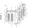
- Molded-in support columns 38 provide dimensional stability to flexible hollow cushion 20. Molded-in support columns 38 are also visible through openings 47 in rigid seat support 10. See Figure 3.
- the hollow interior 41 of flexible hollow cushion 20 may be filled with a material selected from pressurized gases, liquids, gels, polymeric foams and combinations thereof.
- Pressurized gasses that may be used to fill hollow interior 41 include, for example, air and nitrogen, preferably air.
- Liquids that may be used to fill hollow interior 41 include, for example, water, a mixture of water and propylene glycol, and a heat transfer oil.
- Liquids that may be used to fill hollow interior 41 also include viscoelastic liquids, such as viscoelastic liquid polymers, e.g., viscoelastic polyurethanes, that are known to the skilled artisan.
- gel refers to art-recognized gels, which are typically in the form of viscous jellylike materials, that are used to provide cushioning, shock absorption and/or vibrational dampening properties.
- An example of a class of such gels that may be used in the present invention are glycerin gels.
- polymeric foams that may be used to fill hollow interior 41 are preferably flexible polymeric foams, and include those known to the skilled artisan, e.g., flexible polyurethane foams.
- Filling materials such as polymer foams, liquid and liquid gels may be introduced into the flexible hollow member (b) during or after the molding process, e.g., blow molding.
- Filling materials, such as polymeric foams may be introduced into the hollow interior of flexible hollow member (b) during a blow molding process by means of one or more injection needles extending from the interior walls of the blow mold, as is know to the skilled artisan.
- flexible hollow member (b), e.g., flexible hollow cushion 20 comprises means for reversibly increasing pressure within the hollow interior, e.g., hollow interior 41, such as a pressure regulating valve (not shown) that provides gaseous or fluid communication with the hollow interior of cushion 20.
- a pressure regulating valve may be incorporated into flexible hollow cushion 20 during or after the molding processes by which it is formed.
- a pressure regulating valve may be placed into a recess within the inner wall of the mold (the valve extending partially from the recess). During the blow molding process, the valve becomes incorporated into flexible hollow cushion 20.
- a pressure regulating valve may be incorporated into the flexible hollow member (b) after the molding process by means of art recognized methods, which typically include plastic welding techniques, such as thermal welding, radio frequency welding and solvent welding.
- the integral pressure regulating valve (not shown) may be connected to a source of pressurized gas (e.g., a pump or a reservoir connected to a pump, not shown).
- a source of pressurized gas e.g., a pump or a reservoir connected to a pump, not shown.
- An individual sitting on molded seat 2 may then reversibly increase or decrease the pressure within flexible hollow cushion 20 by means of the pressure regulating valve to suit their own comfort.
- the pressure regulating valve may be connected to a source of liquid, such as a reservoir of heat exchange fluid, e.g., a mixture of water and propylene glycol.
- a source of liquid such as a reservoir of heat exchange fluid, e.g., a mixture of water and propylene glycol.
- the liquid can be either heated or cooled (e.g., by means of a heat exchanger, not shown) and pumped into or cycled through flexible hollow cushion 20 by means of one or more pressure regulating valves, e.g., one or more integral pressure regulating valves (not shown).
- the liquid in addition to being either heated or cooled may, for example, also be: (i) controllably pumped into cushion 20 to increase the pressure therein; (ii) cycled through cushion 20 to maintain a selected level of pressure therein; or (iii) controllably released from cushion 20 to decrease the pressure therein.
- Heated liquid that may be introduced into the interior of cushion 20 is typically heated to a temperature greater than or equal to 25°C, e.g., 30°C, 50°C or 70°C.
- Cooled liquid that may be introduced into the interior of cushion 20 is typically cooled to a temperature of less than 25°C, e.g., 20°C, 15°C or 10°C.
- An individual sitting on molded seat 2 may then, in addition to reversibly increasing or decreasing the pressure within flexible hollow cushion 20, also concurrently and reversibly adjust the temperature of cushion 20 to suit their own comfort.
- Flexible hollow cushion 20 may further comprise a fabric covering on at least a portion of its outer surface in an embodiment of the present invention.
- the fabric covering may be pulled over cushion 20 after its formation.
- the fabric covering may be formed on the outer surface of cushion 20 during its formation.
- a fabric insert may be placed over at least a portion of the interior surfaces of the mold. During the blow molding process, the parison contacts and becomes fused with the fabric insert.
- cushion 20 When removed from the mold, cushion 20 has an integral fabric covering on at least a portion of its outer surface.
- flexible hollow member (b), e.g., flexible hollow cushion 20 has an integral film on at least a portion of its outer surface.
- the integral film is formed on the outer surface of the flexible hollow member by means of an in-mold decoration process.
- the integral film is typically a plastic film, e.g., a thermoplastic or thermoset plastic film, and may be clear, tinted or opaque, e.g., pigmented. Additionally, the integral film may have indicia, patterns and/or printing thereon.
- the integral film is a thermoplastic film, e.g., a thermoplastic polyurethane or polycarbonate film.
- the integral film is typically incorporated into the outer surface of cushion 20 during the molding process, i.e., by means of an in-mold decoration process.
- a film insert e.g., a thermoplastic polyurethane film insert
- the parison contacts and becomes fused to the film insert.
- flexible hollow cushion 20 Upon removal from the mold, flexible hollow cushion 20 has an integral film in and/or on at least a portion of its outer surface.
- the film insert may have indicia, patterns and/or printing on at least a portion of one surface, e.g., on at least a portion of its first and/or second surfaces.
- the first surface of the film insert is that surface which contacts the inner surface of the mold.
- the second surface of the film insert is opposite the first surface, faces the interior of the mold, and comes into direct contact with the parison during the blow molding process.
- the exterior surface of flexible hollow cushion 20 may have molded-in texture. Molded-in texture can serve to give cushion 20 a leather-like appearance.
- the molded-in texture is typically formed by a plurality of raised portions and/or recesses on and/or in the interior surface of the mold in which cushion 20 is formed.
- flexible cushion 20 is fixedly attached to rigid seat support 10 by means of attachment heads 44.
- Rigid seat support 10 has a plurality of perforations having edges (not shown). Portions of flexible cushion 20 extend through at least some of these perforations and form attachment heads 44, the edges of the perforations become embedded in the flexible material extending therethrough, and flexible cushion 20 is thus fixedly attached to rigid seat support 10.
- FIG. 1 A sectional representation through line A-A of an attachment head 44 on rigid seat back support 17 of Figure 3, is depicted as attachment means 3 in Figure 4.
- Rigid seat back support 17 has a perforation 53 therein.
- Perforation 53 is defined by deformed edge portions 50.
- perforation 53 may be defined by non-deformed edge portions (not shown).
- a portion of flexible back cushion 23, which abuts surface 56 of support 17, extends through perforation 53 embedding edges 50 therein.
- the portion of flexible back cushion 23 extending through perforation 53 further extends out over surface 59 of support 17 and forms attachment head 44.
- Attachment head 44 of Figure 4 may be shaped by means of corresponding depressions in the interior wall of the mold (not shown).
- the hollow interior 41 of flexible back cushion 23 is in communication with the hollow interior 62 of attachment head 44.
- perforation 53 of smaller diameter and/or flexible thermoplastic material (e.g., of back cushion 23) of greater thickness the flexible material extending through perforation 53 may fuse together, effectively plugging perforation 53 and forming a substantially solid attachment head 44 (not shown).
- Attachment means 5 of Figure 6 is similar to attachment means 3 of Figure 4.
- Attachment head 45 of attachment means 5, however, is substantially flush with second surface 59 of support 17.
- the flush attachment head 45 is formed by means of the interior surface of the mold being substantially flush or in abutment with second surface 59 of support 17.
- flexible thermoplastic cushion 20 of molded seat 2 may be further fixedly attached to rigid seat support 10 by attachment means selected from fasteners, adhesives and combinations thereof.
- attachment means selected from fasteners, adhesives and combinations thereof.
- fasteners include, but are not limited to, screws, e.g., sheet metal screws, nuts and bolts, and metal rivets.
- Adhesives that may be used include those that are known to the skilled artisan, e.g., epoxy resin based adhesives.
- the term "adhesives” refers to: (i) adhesive materials that are separate from the rigid support and the flexible thermoplastic member, e.g., epoxy resin based adhesives; and (ii) cohesive adhesion between the rigid support and the flexible thermoplastic member.
- the rigid support (a) is fabricated from steel, poly(acrylonitrile-butadiene-styrene) or polycarbonate
- the flexible hollow thermoplastic member (b) is fabricated from thermoplastic polyurethane, and cohesive adhesion results from their mutual abutment.
- rigid seat support 10 and molded flexible hollow cushion 20 are each fabricated separately, and then cushion 20 is fixedly attached to rigid support 10.
- Cushion 20 is positioned in abutting relation with a first surface of rigid seat support 10, such that at least some of the perforations 53 in support 10 are covered by cushion 20.
- at least those portions of cushion 20 that cover perforations 53 are heated to soften the thermoplastic material of cushion 20.
- Reduced pressure is formed on the side of support 10 that is opposite its first surface (i.e., the second surface of support 10), and/or increased pressure is formed on the interior of cushion 20.
- Those softened portions of cushion 10 are thus drawn through perforations 53, embedding edges 50 in the thermoplastic material extending therethrough, and forming attachment heads 44 on the second surface of support 10.
- flexible hollow cushion 20 is fixedly attached to rigid seat support 10 during the blow molding formation of cushion 20.
- Rigid seat support 10, having a plurality of perforations 53 is placed on one side of the blow mold, its second surface facing the interior surface of the mold wall, and its first surface facing the open interior of the mold.
- a parison precursor of flexible hollow cushion 20 is blow molded onto the first surface of rigid support 10, a portion of the thermoplastic material of the parison extends through at least some of perforations 53 of support 10 to form attachment heads 44. Edges 50 of perforations 53 become embedded in the thermoplastic material of the parison extending therethrough, thereby fixedly attaching flexible cushion 20 to rigid seat support 10.
- the parison is extended through perforations 53 by the concurrent implementation of methods (i) and (ii).
- the rigid support (a) may have extensions, e.g., anchoring extensions, which extend into the flexible thermoplastic hollow member (b).
- Each extension has walls, e.g., side walls, a hollow interior (e.g., a chamber), and at least one perforation in its walls. Portions of the flexible hollow member (b) extend through the perforations of the anchoring extensions and into the chamber thereof.
- all of the perforations of the rigid support (a) are located within the walls of the anchoring extensions, and the flexible hollow member (b) is fixedly attached to rigid support (a) by means of the anchoring extensions.
- the anchoring extensions may have any desired shape, but are typically substantially cylindrical.
- Extension 68 has walls 79 and a perforation 71.
- Perforation 71 has edges 82 which are embedded in the flexible thermoplastic material of cushion 23 which extends therethrough.
- the flexible thermoplastic material of cushion 23 extending through perforation 71 forms attachment head 77 within chamber 65 of extension 68.
- Rigid back support 17 has a perforation 74 therein which is in communication with chamber 65 of extension 68.
- Perforation 74 can be used to form a vacuum within chamber 65, to assist in drawing attachment head 77 therein during molding operations, e.g., blow molding.
- a reversibly retractable core pin may be extended from the interior wall of the mold through perforation 74 into chamber 65 to provide a limiting surface against which attachment head 77 abuts during its formation, as is known to the skilled artisan. While anchoring extension 68 is depicted as having only one perforation 71 in Figure 5, it may have a plurality of perforations through which the flexible material of cushion 23 extends to form additional attachment heads within chamber 65.
- thermosetting polymer composition e.g., a two-pack epoxy or polyurethane composition
- the introduced thermosetting polymer composition at least partially fills chamber 65 and serves to protect and hold attachment head 77 in place.
- rigid support (a) has edges which are at least partially embedded in portions of flexible hollow member (b) that are wrapped there around (wrap-around attachment means).
- a sectional representation of a wrap-around attachment means 8 is depicted in Figure 7.
- edge portion 85 of rigid support 17 (also shown within highlighted area 88 of Figure 3) has an extension 91 which is embedded in the flexible thermoplastic material of back cushion 23.
- wrap-around attachment means are preferably formed during the blow molding formation of flexible cushion 20 (including back cushion portion 23). Wrap-around attachment means, such as attachment means 8 of Figure 7, serve to further fixedly attach flexible hollow member (b) to rigid support (a) of the molded article of the present invention.
- extension 91 of wrap-around attachment means 8 is not present, and edge portion 85 is beveled or chamfered (not shown).
- the beveled edge portion of the rigid support (a) is at least partially embedded in portions of the thermoplastic material of flexible hollow member (b) that are wrapped there around.
- the rigid support (a) of the molded article of the present invention may be solid or hollow.
- the rigid support (a) is a rigid hollow support (e.g., a rigid substantially tubular support) having an exterior (first) surface, an internal (second) surface defining the hollow interior of the hollow support, and a plurality of perforations. At least a portion of the flexible hollow thermoplastic member (b) extends through at least some of the perforations into the hollow interior of the rigid hollow support (a).
- Molded articles according to the present invention include, but are not limited to: seats, such as chairs (e.g., indoor chairs and outdoor chairs, such as patio furniture), bleachers, bicycle seats, tractor seats and motor cycle seats; cushioned panels, such as cushioned wall panels and cushioned door panels; and automotive air-bags.
- Seats such as chairs (e.g., indoor chairs and outdoor chairs, such as patio furniture), bleachers, bicycle seats, tractor seats and motor cycle seats; cushioned panels, such as cushioned wall panels and cushioned door panels; and automotive air-bags.
- Cushioned wall panels according to the present invention include, for example, cushioned wall panels that may be use in gymnasiums, e.g., on the gymnasium walls behind a basket ball hoop.
Landscapes
- Engineering & Computer Science (AREA)
- Manufacturing & Machinery (AREA)
- Mechanical Engineering (AREA)
- Blow-Moulding Or Thermoforming Of Plastics Or The Like (AREA)
Abstract
Description
- The present invention relates to a molded article comprising a rigid support having a plurality of perforations, and a molded flexible hollow member of thermoplastic material. Portions of the flexible hollow member extend through at least some of the perforations of the rigid support, and the edges of the perforations are embedded in the flexible material extending there through. The flexible material extending through the perforations serves to fixedly attach the flexible member to the rigid support. The present invention also relates to a process of preparing the molded article.
- Flexible hollow thermoplastic articles, e.g., cushions, can be prepared by means of thermoplastic blow molding processes. Blow molding typically involves a multi-stage process. In the first stage, a flexible thermoplastic feed material, e.g., in the form of pellets, is extruded, typically in an extruder, and the resulting molten extrudate is passed through a die to form a hollow molten tube, which is referred to as a parison. The parison is drawn through or into an open mold. The mold is closed around the parison, pinching off at least one end of the parison. Compressed gas is then fed into the interior of the parison, which expands to fill the interior of the closed mold. While maintaining the internal pressure within the parison, the expanded parison is allowed to cool and solidify within the mold. The pressure within the solidified parison is released, the mold is opened, and a flexible hollow blow molded article is removed. Flexible hollow thermoplastic articles may also be prepared by other art recognized processes, which include, for example, twin-sheet thermoforming, rotational molding, thermoplastic welding (e.g., vibration and/or radio frequency welding), two-piece over-molding and lost-core molding.
- The flexible hollow thermoplastic member or bladder, prepared for example by blow molding, is typically attached to a support structure. In the case of seat cushions, the flexible hollow thermoplastic bladder is attached to a seat back support and/or seat bottom support by means of, for example, a fabric jacket. The fabric jacket is attached to the support structure, e.g., by means of rivets and/or loops, and covers and tightly holds the flexible hollow thermoplastic bladder against the support structure. The flexible bladder may also be further or alternatively attached to the support structure by means of, for example, adhesives. The flexible bladder or cushion may be filled with air, or another material, such as a polymeric foam, e.g., a polyurethane foam.
- Such methods of attaching flexible hollow thermoplastic bladders or cushions to a support structure, as described above, typically involve a series of manufacturing steps, and the use of additional materials, e.g., fabric jackets, rivets and adhesives. In addition, the position of the flexible hollow thermoplastic bladder or cushion can undesirably shift relative to or pull away from the support structure.
- A need accordingly exists to develop molded articles, e.g., cushioned seats, in which the molded flexible hollow thermoplastic member, such as a bladder or cushion, is more securely fixed or attached to the rigid support of the article. A need also exists with regard to the development of new methods of preparing such molded articles in which the flexible member is concurrently molded and fixedly attached to the support structure, thereby reducing the number of manufacturing steps required.
- United States Patent No. 6,120,100 discloses a head rest assembly that is fabricated by a blow molding process, and which includes a skin surrounding a foam cushion, and an insert secured to the skin. The skin includes a channel dimensioned to receive the peripheral edge of the insert therein. The insert may be adhered to the skin either before or during the blow molding process.
- In accordance with the present invention, there is provided a molded article comprising:
- (a) a rigid support having a surface and a plurality of perforations having edges; and
- (b) a molded flexible member of thermoplastic material, at least a portion of said flexible member being in abutting relationship with at least a portion of the surface of said support, said flexible member having a hollow interior, wherein a portion of said flexible member extends through at least some of the perforations of said rigid support, the edges of said perforations being embedded in the portions of the flexible member extending therethrough, thereby fixedly attaching said flexible member to said rigid support.
-
- In further accordance with the present invention, there is also provided a method of preparing a molded article comprising a molded flexible hollow thermoplastic member fixedly attached to a rigid support, said method comprising:
- (a) placing said rigid support in a mold, said rigid support having a plurality of perforations having edges, a first surface and a second surface; and
- (b) blow molding a thermoplastic parison precursor of said flexible member against the first surface of said rigid support; wherein a portion of the thermoplastic material of said thermoplastic parison extends through at least some of said perforations of said rigid support, the edges of said perforations being embedded in the plastic material extending therethrough, thereby attaching fixedly said flexible member to said rigid support.
-
- The features that characterize the present invention are pointed out with particularity in the claims, which are annexed to and form a part of this disclosure. These and other features of the invention, its operating advantages and the specific objects obtained by its use will be more fully understood from the following detailed description and accompanying drawings in which preferred embodiments of the invention are illustrated and described.
- Unless otherwise indicated, all numbers or expressions, such as those expressing structural dimensions, quantities of ingredients, etc. used in the specification and claims are understood as modified in all instances by the term "about."
-
- Figure 1 is a representative perspective view of a molded seat
according to the present invention which comprises a
rigid support 10 and a molded flexible hollowthermoplastic member 20 fixedly attached thereto; - Figure 2 is a representative partial cut-away perspective view of the molded seat of Figure 1;
- Figure 3 is a representative perspective view of the back of the molded seat of Figure 1;
- Figure 4 is a representation of a section of an attachment means through line A-A of Figure 3;
- Figure 5 is a sectional representation of an anchoring extension extending into the molded flexible hollow thermoplastic member of a molded seat according to the present invention;
- Figure 6 is a sectional representation of an attachment means similar to that of Figure 4; and
- Figure 7 is a sectional representation of a wrap-around attachment means, in which a portion of flexible hollow member (b) wraps around and embeds at least a portion of the edges of rigid support (a) therein.
-
- In Figures 1 through 7, like reference numerals designate the same components and structural features.
- Referring now to Figure 1 of the drawings, there is shown a molded
seat 2 according to the present invention, which includes arigid seat support 10 and a moldedflexible cushion 20.Rigid seat support 10 is a unitary unit and includes a rigidseat back support 17 and a rigidseat bottom support 14.Flexible cushion 20 is a continuous member and includes aback cushion portion 23 and abottom cushion portion 26. The outer surface offlexible cushion 20 has raised molded-infeatures 29. Rigidseat support bottom 14 includesflanges 32 havingholes 35 therein, which provide means by which moldedseat 2 can be fixedly attached to a separate support structure, e.g., the interior of a vehicle or the deck of a tractor or boat (not shown). Rigid seat support back 17 may also further include flanges (not shown) for fixedly attaching moldedseat 2 to a separate support structure (not shown). - The rigid support (a), e.g.,
rigid seat support 10 of moldedseat 2, of the molded article of the present invention may be selected from metal, thermoset plastic material, thermoplastic material and combinations thereof. Metals from which rigid support (a) may be selected include, but are not limited to, aluminum and steel. As used herein and in the claims the term "thermoset plastic material" means plastic materials having a three dimensional crosslinked network resulting from the formation of covalent bonds between chemically reactive groups, e.g., active hydrogen groups and free isocyanate groups. Thermoset plastic materials from which rigid support (a) may be fabricated include those known to the skilled artisan, e.g., crosslinked polyurethanes, crosslinked polyepoxides and crosslinked polyesters. Of the thermoset plastic materials, crosslinked polyurethanes are preferred.Rigid support 10 may be fabricated from crosslinked polyurethanes by the art-recognized process of reaction injection molding. Reaction injection molding typically involves, as is known to the skilled artisan, injecting separately, and preferably simultaneously, into a mold: (i) an active hydrogen functional component (e.g., a polyol and/or polyamine); and (ii) an isocyanate functional component (e.g., a diisocyanate such as toluene diisocyanate, and/or dimers and trimers of a diisocyanate such as toluene diisocyanate). The filled mold may optionally be heated to ensure and/or hasten complete reaction of the injected components. Upon complete reaction of the injected components, the mold is opened and the molded article, e.g., rigid support (a), is removed. - As used herein and in the claims, the term "thermoplastic material" means a plastic material that has a softening or melting point, and is substantially free of a three dimensional crosslinked network resulting from the formation of covalent bonds between chemically reactive groups, e.g., active hydrogen groups and free isocyanate groups. Examples of thermoplastic materials from which rigid support (a), e.g.,
rigid seat support 10 of moldedseat 2, may be fabricated include, but are not limited to, thermoplastic polyurea, thermoplastic polyimide, thermoplastic polyamide, thermoplastic polyamideimide, thermoplastic polyester, thermoplastic polycarbonate, thermoplastic polysulfone, thermoplastic polyketone, thermoplastic polyethylene, thermoplastic polypropylene, thermoplastic polybutylene terephthalate, thermoplastic polyvinylchloride, thermoplastic acrylonitrile-butadiene-styrene, thermoplastic polyurethane and mixtures or thermoplastic compositions containing one or more thereof. Of the thermoplastic materials from which rigid support (a) may be fabricated, thermoplastic polyamides are preferred. - Rigid support (a) may be fabricated from thermoplastic materials by the art-recognized process of injection molding, in which a molten stream of thermoplastic material, e.g., molten thermoplastic polyamide, is injected into a mold, e.g., an optionally heated mold. Upon cooling the filled mold, the molded article, e.g., rigid support (a), is removed. A preferred thermoplastic material from which rigid support (a) may be fabricated is thermoplastic polyamide, e.g., DURETHAN thermoplastic polyamide, commercially available from Bayer Corporation. Other art-recognized processes by which rigid support (a) may be fabricated from thermoplastic materials include, but are not limited to, blow molding and thermoforming.
- The thermoset plastic materials and/or thermoplastic materials from which rigid support (a) may be fabricated, may optionally be reinforced with a material selected from glass fibers, carbon fibers, boron fibers, metal fibers, polyamide fibers (e.g., KEVLAR polyamide fibers) and mixtures thereof. The reinforcing fibers, and the glass fibers in particular, may have sizings on their surfaces to improve miscibility and/or adhesion to the plastics into which they are incorporated, as is known to the skilled artisan. Glass fibers are a preferred reinforcing material in the present invention. If used, the reinforcement material, e.g., glass fibers, is typically present in the thermoset plastic materials and/or thermoplastic materials of elongated
rigid support 10 in a reinforcing amount, e.g., in an amount of from 5 percent by weight to 60 percent by weight, based on the total weight of rigid support (a). - As used herein and in the claims, the term "rigid" of rigid support (a) is used relative to the term "flexible" of the molded flexible thermoplastic member (b). That is, the rigid support (a) is more rigid than is the flexible hollow member (b), and correspondingly the flexible hollow member (b) is more flexible than the rigid support (a). More specifically, the rigid support (a), when fabricated from a thermoplastic or a thermoset material, typically has a flexural modulus of at least 1000 MPa, e.g., from 1000 to 15,000 MPa. The flexible hollow member (b) typically has a flexural modulus of less than 1000 MPa, e.g., less than 100 MPa or less than 70 MPa.
- The thermoplastic material of the molded flexible hollow member (b), e.g.,
flexible thermoplastic cushion 20 of moldedseat 2, is selected from at least one of thermoplastic vulcanizates, thermoplastic polyolefins, thermoplastic polyurethanes, thermoplastic polyureas, thermoplastic polyamides, thermoplastic polyesters and thermoplastic polycarbonates. Thermoplastic vulcanizates are vulcanized alloys of rubber and thermoplastic materials, having rubber and thermoplastic phases. The rubber phase of thermoplastic vulcanizates that may be used in the present invention include, but are not limited to, ethylene propylene diene rubber, natural rubber and butyl rubber. Examples of thermoplastics that may form the thermoplastic phase of the thermoplastic vulcanizates include, for example, polypropylene and polyethylene. Commercially available thermoplastic vulcanizates that may be used in the present invention include, for example, KRATON polymers, commercially available from GLS Corporation, and SANTOPRENE polymers, commercially available from Advanced Elastomers Systems. - Thermoplastic polyolefins from which the flexible hollow member (b) may be fabricated include, for example, polyethylene, polypropylene, copolymers of ethylene and propylene, and polybutylene. Preferred thermoplastic polyolefins include, but are not limited to, linear low-density polyethylene (LLDPE) and metallocene linear low-density polyethylene (mLLDPE). In a preferred embodiment of the present invention, flexible hollow thermoplastic member (b) is fabricated from thermoplastic polyurethane, e.g., TEXIN thermoplastic polyurethane or DESMOPAN thermoplastic polyurethane which are commercially available from Bayer Corporation.
- The plastic materials of rigid support (a) and flexible thermoplastic hollow member (b) may each independently further contain one or more functional additives. Additives that may be present in the plastic material of the rigid support (a) and/or the flexible thermoplastic hollow member (b) of the molded article include, but are not limited to, antioxidants, colorants, e.g., pigments and/or dyes, mold release agents, fillers, e.g., calcium carbonate, ultraviolet light absorbers, fire retardants and mixtures thereof. Additives may be present in the plastic material of the rigid support and/or the flexible thermoplastic hollow member in functionally sufficient amounts, e.g., in amounts independently from 0.1 percent by weight to 10 percent by weight, based on the total weight of the plastic material of the rigid support or the flexible thermoplastic hollow member.
- The flexible thermoplastic hollow member (b), e.g.,
flexible cushion 20, of the molded article of the present invention, may be formed by methods that are known to those of ordinary skill in the art. Such art recognized methods by which the flexible thermoplastic hollow member (b) may be prepared include, but are not limited to, blow molding, twin-sheet thermoforming, rotational molding, thermoplastic welding (e.g., vibration and/or radio frequency welding), two-piece over-molding and lost-core molding. In a preferred embodiment of the present invention, the flexible hollow thermoplastic member (b) is prepared by blow molding. The blow molding process is well known to the skilled artisan, and has been described previously herein. - In Figure 2 a sectional perspective view of molded
seat 2 of Figure 1 is depicted. The sectional perspective view reveals thehollow interior 41 of flexiblethermoplastic cushion 20. Molded-in support columns (or ribs) 38, which are continuous with molded-infeatures 29, are also visible in Figure 2. Molded-insupport columns 38 are composed of the same flexible thermoplastic material as that of, and are continuous with flexiblehollow cushion 20. Typically, molded-insupport columns 38 are formed concurrently with the formation of flexiblehollow member 20. For example, when formed by blow molding, the interior walls of the mold may have portions extending therefrom that serve to form molded-insupport columns 38. Those portions of the mold interior that are opposite the mold extensions, may have depressions therein that serve to form molded-infeatures 29 during the blow molding process. Molded-insupport columns 38 provide dimensional stability to flexiblehollow cushion 20. Molded-insupport columns 38 are also visible throughopenings 47 inrigid seat support 10. See Figure 3. - The
hollow interior 41 of flexiblehollow cushion 20 may be filled with a material selected from pressurized gases, liquids, gels, polymeric foams and combinations thereof. Pressurized gasses that may be used to fillhollow interior 41 include, for example, air and nitrogen, preferably air. Liquids that may be used to fillhollow interior 41 include, for example, water, a mixture of water and propylene glycol, and a heat transfer oil. Liquids that may be used to fillhollow interior 41 also include viscoelastic liquids, such as viscoelastic liquid polymers, e.g., viscoelastic polyurethanes, that are known to the skilled artisan. The term "gel" as used herein and in the claims, with regard to filling the hollow interior of the flexible member of the molded article of the present invention, refers to art-recognized gels, which are typically in the form of viscous jellylike materials, that are used to provide cushioning, shock absorption and/or vibrational dampening properties. An example of a class of such gels that may be used in the present invention are glycerin gels. Examples of polymeric foams that may be used to fillhollow interior 41 are preferably flexible polymeric foams, and include those known to the skilled artisan, e.g., flexible polyurethane foams. - Filling materials, such as polymer foams, liquid and liquid gels may be introduced into the flexible hollow member (b) during or after the molding process, e.g., blow molding. Filling materials, such as polymeric foams, may be introduced into the hollow interior of flexible hollow member (b) during a blow molding process by means of one or more injection needles extending from the interior walls of the blow mold, as is know to the skilled artisan.
- In an embodiment of the present invention, flexible hollow member (b), e.g., flexible
hollow cushion 20, comprises means for reversibly increasing pressure within the hollow interior, e.g.,hollow interior 41, such as a pressure regulating valve (not shown) that provides gaseous or fluid communication with the hollow interior ofcushion 20. A pressure regulating valve may be incorporated into flexiblehollow cushion 20 during or after the molding processes by which it is formed. In the case of blow molding, a pressure regulating valve may be placed into a recess within the inner wall of the mold (the valve extending partially from the recess). During the blow molding process, the valve becomes incorporated into flexiblehollow cushion 20. A pressure regulating valve may be incorporated into the flexible hollow member (b) after the molding process by means of art recognized methods, which typically include plastic welding techniques, such as thermal welding, radio frequency welding and solvent welding. - During use of molded
seat 2, the integral pressure regulating valve (not shown) may be connected to a source of pressurized gas (e.g., a pump or a reservoir connected to a pump, not shown). An individual sitting on moldedseat 2, may then reversibly increase or decrease the pressure within flexiblehollow cushion 20 by means of the pressure regulating valve to suit their own comfort. - Alternatively, the pressure regulating valve (not shown) may be connected to a source of liquid, such as a reservoir of heat exchange fluid, e.g., a mixture of water and propylene glycol. The liquid can be either heated or cooled (e.g., by means of a heat exchanger, not shown) and pumped into or cycled through flexible
hollow cushion 20 by means of one or more pressure regulating valves, e.g., one or more integral pressure regulating valves (not shown). The liquid, in addition to being either heated or cooled may, for example, also be: (i) controllably pumped intocushion 20 to increase the pressure therein; (ii) cycled throughcushion 20 to maintain a selected level of pressure therein; or (iii) controllably released fromcushion 20 to decrease the pressure therein. Heated liquid that may be introduced into the interior ofcushion 20 is typically heated to a temperature greater than or equal to 25°C, e.g., 30°C, 50°C or 70°C. Cooled liquid that may be introduced into the interior ofcushion 20 is typically cooled to a temperature of less than 25°C, e.g., 20°C, 15°C or 10°C. An individual sitting on moldedseat 2, may then, in addition to reversibly increasing or decreasing the pressure within flexiblehollow cushion 20, also concurrently and reversibly adjust the temperature ofcushion 20 to suit their own comfort. - Flexible
hollow cushion 20 may further comprise a fabric covering on at least a portion of its outer surface in an embodiment of the present invention. The fabric covering may be pulled overcushion 20 after its formation. Alternatively, the fabric covering may be formed on the outer surface ofcushion 20 during its formation. When prepared by blow molding, a fabric insert may be placed over at least a portion of the interior surfaces of the mold. During the blow molding process, the parison contacts and becomes fused with the fabric insert. When removed from the mold,cushion 20 has an integral fabric covering on at least a portion of its outer surface. - In an embodiment of the present invention, flexible hollow member (b), e.g., flexible
hollow cushion 20, has an integral film on at least a portion of its outer surface. The integral film is formed on the outer surface of the flexible hollow member by means of an in-mold decoration process. The integral film is typically a plastic film, e.g., a thermoplastic or thermoset plastic film, and may be clear, tinted or opaque, e.g., pigmented. Additionally, the integral film may have indicia, patterns and/or printing thereon. Preferably the integral film is a thermoplastic film, e.g., a thermoplastic polyurethane or polycarbonate film. The integral film is typically incorporated into the outer surface ofcushion 20 during the molding process, i.e., by means of an in-mold decoration process. When prepared by blow molding, a film insert, e.g., a thermoplastic polyurethane film insert, is typically placed in contact with at least a portion of the interior surface of the mold. During the blow molding process, the parison contacts and becomes fused to the film insert. Upon removal from the mold, flexiblehollow cushion 20 has an integral film in and/or on at least a portion of its outer surface. - The film insert may have indicia, patterns and/or printing on at least a portion of one surface, e.g., on at least a portion of its first and/or second surfaces. The first surface of the film insert is that surface which contacts the inner surface of the mold. The second surface of the film insert is opposite the first surface, faces the interior of the mold, and comes into direct contact with the parison during the blow molding process.
- The exterior surface of flexible
hollow cushion 20 may have molded-in texture. Molded-in texture can serve to give cushion 20 a leather-like appearance. The molded-in texture is typically formed by a plurality of raised portions and/or recesses on and/or in the interior surface of the mold in whichcushion 20 is formed. - With reference to Figures 3 and 4,
flexible cushion 20 is fixedly attached torigid seat support 10 by means of attachment heads 44.Rigid seat support 10 has a plurality of perforations having edges (not shown). Portions offlexible cushion 20 extend through at least some of these perforations and form attachment heads 44, the edges of the perforations become embedded in the flexible material extending therethrough, andflexible cushion 20 is thus fixedly attached torigid seat support 10. - A sectional representation through line A-A of an
attachment head 44 on rigid seat backsupport 17 of Figure 3, is depicted as attachment means 3 in Figure 4. Rigid seat backsupport 17 has aperforation 53 therein.Perforation 53 is defined bydeformed edge portions 50. Alternatively,perforation 53 may be defined by non-deformed edge portions (not shown). A portion offlexible back cushion 23, which abutssurface 56 ofsupport 17, extends throughperforation 53 embeddingedges 50 therein. The portion offlexible back cushion 23 extending throughperforation 53, further extends out oversurface 59 ofsupport 17 andforms attachment head 44.Attachment head 44 of Figure 4 may be shaped by means of corresponding depressions in the interior wall of the mold (not shown). - In Figure 4, the
hollow interior 41 offlexible back cushion 23 is in communication with thehollow interior 62 ofattachment head 44. By selectingperforation 53 of smaller diameter and/or flexible thermoplastic material (e.g., of back cushion 23) of greater thickness, the flexible material extending throughperforation 53 may fuse together, effectively pluggingperforation 53 and forming a substantially solid attachment head 44 (not shown). - Attachment means 5 of Figure 6 is similar to attachment means 3 of Figure 4.
Attachment head 45 of attachment means 5, however, is substantially flush withsecond surface 59 ofsupport 17. Theflush attachment head 45 is formed by means of the interior surface of the mold being substantially flush or in abutment withsecond surface 59 ofsupport 17. - In addition to attachment means 3 and 5 of Figures 4 and 6,
flexible thermoplastic cushion 20 of moldedseat 2 may be further fixedly attached torigid seat support 10 by attachment means selected from fasteners, adhesives and combinations thereof. Examples of fasteners that may be used in the present invention include, but are not limited to, screws, e.g., sheet metal screws, nuts and bolts, and metal rivets. Adhesives that may be used include those that are known to the skilled artisan, e.g., epoxy resin based adhesives. - As used herein and in the claims, the term "adhesives" refers to: (i) adhesive materials that are separate from the rigid support and the flexible thermoplastic member, e.g., epoxy resin based adhesives; and (ii) cohesive adhesion between the rigid support and the flexible thermoplastic member. The materials from which each of the rigid support and the flexible thermoplastic member may be selected such that cohesive adhesion therebetween results from their mutual abutment. In an embodiment of the present invention, the rigid support (a) is fabricated from steel, poly(acrylonitrile-butadiene-styrene) or polycarbonate, and the flexible hollow thermoplastic member (b) is fabricated from thermoplastic polyurethane, and cohesive adhesion results from their mutual abutment.
- In an embodiment of the present invention,
rigid seat support 10 and molded flexiblehollow cushion 20 are each fabricated separately, and then cushion 20 is fixedly attached torigid support 10.Cushion 20 is positioned in abutting relation with a first surface ofrigid seat support 10, such that at least some of theperforations 53 insupport 10 are covered bycushion 20. Typically, at least those portions ofcushion 20 that coverperforations 53 are heated to soften the thermoplastic material ofcushion 20. Reduced pressure is formed on the side ofsupport 10 that is opposite its first surface (i.e., the second surface of support 10), and/or increased pressure is formed on the interior ofcushion 20. Those softened portions ofcushion 10 are thus drawn throughperforations 53, embeddingedges 50 in the thermoplastic material extending therethrough, and forming attachment heads 44 on the second surface ofsupport 10. - In a preferred embodiment of the present invention, flexible
hollow cushion 20 is fixedly attached torigid seat support 10 during the blow molding formation ofcushion 20.Rigid seat support 10, having a plurality ofperforations 53, is placed on one side of the blow mold, its second surface facing the interior surface of the mold wall, and its first surface facing the open interior of the mold. A parison precursor of flexiblehollow cushion 20 is blow molded onto the first surface ofrigid support 10, a portion of the thermoplastic material of the parison extends through at least some ofperforations 53 ofsupport 10 to form attachment heads 44.Edges 50 ofperforations 53 become embedded in the thermoplastic material of the parison extending therethrough, thereby fixedly attachingflexible cushion 20 torigid seat support 10. - To assist the extension of portions of the parison through
perforations 53, at least one of: (i) increased gaseous pressure is provided on the interior of the thermoplastic parison; and (ii) reduced gaseous pressure is provided on the second surface ofrigid support 10, thereby forcing (e.g., drawing and/or pushing) portions of the thermoplastic parison through at least some ofperforations 53. In an embodiment of the present invention, the parison is extended throughperforations 53 by the concurrent implementation of methods (i) and (ii). - The rigid support (a) may have extensions, e.g., anchoring extensions, which extend into the flexible thermoplastic hollow member (b). Each extension has walls, e.g., side walls, a hollow interior (e.g., a chamber), and at least one perforation in its walls. Portions of the flexible hollow member (b) extend through the perforations of the anchoring extensions and into the chamber thereof. In an embodiment of the present invention, all of the perforations of the rigid support (a) are located within the walls of the anchoring extensions, and the flexible hollow member (b) is fixedly attached to rigid support (a) by means of the anchoring extensions. The anchoring extensions may have any desired shape, but are typically substantially cylindrical.
- In Figure 5, a sectional view of an anchoring
extension 68 extending into flexibleback cushion portion 23 is depicted.Extension 68 haswalls 79 and aperforation 71.Perforation 71 hasedges 82 which are embedded in the flexible thermoplastic material ofcushion 23 which extends therethrough. The flexible thermoplastic material ofcushion 23 extending throughperforation 71 forms attachment head 77 withinchamber 65 ofextension 68.Rigid back support 17 has aperforation 74 therein which is in communication withchamber 65 ofextension 68.Perforation 74 can be used to form a vacuum withinchamber 65, to assist in drawing attachment head 77 therein during molding operations, e.g., blow molding. To prevent attachment head 77 from bursting during the blow molding process, a reversibly retractable core pin (not shown) may be extended from the interior wall of the mold throughperforation 74 intochamber 65 to provide a limiting surface against which attachment head 77 abuts during its formation, as is known to the skilled artisan. While anchoringextension 68 is depicted as having only oneperforation 71 in Figure 5, it may have a plurality of perforations through which the flexible material ofcushion 23 extends to form additional attachment heads withinchamber 65. - An advantage of using anchoring extensions to fixedly attach
cushion 20 torigid support 10 is the recession and accompanying protection that is afforded attachment head 77 withinchamber 65. After formation of moldedseat 2, a thermosetting polymer composition, e.g., a two-pack epoxy or polyurethane composition, can be introduced intochamber 65 by means ofperforation 74. The introduced thermosetting polymer composition at least partially fillschamber 65 and serves to protect and hold attachment head 77 in place. - In an embodiment of the present invention, rigid support (a) has edges which are at least partially embedded in portions of flexible hollow member (b) that are wrapped there around (wrap-around attachment means). A sectional representation of a wrap-around attachment means 8 is depicted in Figure 7. With further reference to Figure 7,
edge portion 85 of rigid support 17 (also shown within highlightedarea 88 of Figure 3) has anextension 91 which is embedded in the flexible thermoplastic material ofback cushion 23. Such wrap-around attachment means are preferably formed during the blow molding formation of flexible cushion 20 (including back cushion portion 23). Wrap-around attachment means, such as attachment means 8 of Figure 7, serve to further fixedly attach flexible hollow member (b) to rigid support (a) of the molded article of the present invention. In another embodiment of the present invention (not shown),extension 91 of wrap-around attachment means 8 is not present, andedge portion 85 is beveled or chamfered (not shown). The beveled edge portion of the rigid support (a) is at least partially embedded in portions of the thermoplastic material of flexible hollow member (b) that are wrapped there around. - The rigid support (a) of the molded article of the present invention may be solid or hollow. In an embodiment of the present invention, the rigid support (a) is a rigid hollow support (e.g., a rigid substantially tubular support) having an exterior (first) surface, an internal (second) surface defining the hollow interior of the hollow support, and a plurality of perforations. At least a portion of the flexible hollow thermoplastic member (b) extends through at least some of the perforations into the hollow interior of the rigid hollow support (a).
- Molded articles according to the present invention include, but are not limited to: seats, such as chairs (e.g., indoor chairs and outdoor chairs, such as patio furniture), bleachers, bicycle seats, tractor seats and motor cycle seats; cushioned panels, such as cushioned wall panels and cushioned door panels; and automotive air-bags. Cushioned wall panels according to the present invention include, for example, cushioned wall panels that may be use in gymnasiums, e.g., on the gymnasium walls behind a basket ball hoop.
- The present invention has been described with reference to specific details of particular embodiments thereof. It is not intended that such details be regarded as limitations upon the scope of the invention except insofar as and to the extent that they are included in the accompanying claims.
Claims (36)
- A molded article comprising:wherein a portion of said flexible member extends through at least some of the perforations of said rigid support, the edges of said perforations being embedded in the portions of the flexible member extending therethrough, thereby fixedly attaching said flexible member to said rigid support.(a) a rigid support having a surface and a plurality of perforations having edges; and(b) a molded flexible member of thermoplastic material, at least a portion of said flexible member being in abutting relationship with at least a portion of the surface of said support, said flexible member having a hollow interior,
- The article of Claim 1 wherein said rigid support is fabricated from a material selected from metal, thermoset plastic material, thermoplastic material and combinations thereof.
- The article of Claim 2 wherein said rigid support is fabricated from thermoplastic material optionally reinforced with a material selected from glass fibers, carbon fibers, metal fibers, polyamide fibers and mixtures thereof.
- The article of Claim 1 wherein the thermoplastic material of said flexible member is selected from at least one of thermoplastic vulcanizates, thermoplastic polyolefins, thermoplastic polyurethanes, thermoplastic polyureas, thermoplastic polyamides, thermoplastic polyesters and thermoplastic polycarbonates.
- The article of Claim 1 wherein said flexible member has an outer surface, said flexible member further comprising a fabric covering on at least a portion its outer surface.
- The article of Claim 1 wherein said flexible member has an outer surface, at least a portion of said outer surface having molded-in texture.
- The article of Claim 1 wherein said flexible member has an outer surface, said flexible member further comprising an integral film on at least a portion of said outer surface, said integral film being formed on said outer surface by means of an in-mold decoration process.
- The article of Claim 1 wherein said flexible member is further fixedly attached to said rigid support by attachment means selected from fasteners, adhesives and combinations thereof.
- The article of Claim 1 wherein the interior of said flexible member is filled with a material selected from, pressurized gas, liquid, gel, polymeric foam and combinations thereof.
- The article of Claim 1 wherein said flexible member comprises means for reversibly increasing pressure within the hollow interior of said flexible member.
- The article of Claim 10 wherein said means for reversibly increasing pressure within the hollow interior of said flexible member comprises at least one pressure regulating valve that provides fluid communication with the hollow interior of said flexible member, and one of (i) a heated liquid and (ii) a cooled liquid are reversibly introduced into the hollow interior of said flexible member through said at least one pressure regulating valve.
- The article of Claim 1 wherein said article is a seat.
- The article of Claim 12 wherein said rigid support comprises a rigid seat back support and a rigid seat bottom support, and said flexible member comprises flexible cushions fixedly attached to each of said rigid seat back support and rigid seat bottom support.
- The article of Claim 12 wherein said rigid support is a continuous unitary unit.
- The article of Claim 1 wherein at least some of said perforations have deformed edge portions, and said deformed edge portions are embedded in the flexible member material extending therethrough.
- The article of Claim 1 wherein said rigid support (a) is a rigid hollow support having an exterior surface and a hollow interior, said flexible member (b) being in abutting relationship with at least a portion of the exterior surface of said hollow support, at least a portion of said flexible member (b) extends through at least some of said perforations into the hollow interior of said rigid hollow support.
- The molded article of Claim 1 wherein said rigid support (a) has a plurality of anchoring extensions extending into said flexible member (b), each of said anchoring extensions having walls, an interior chamber and at least one wall perforation in said walls, each wall perforation having edges, a portion of said flexible member (b) extends through at least some of said wall perforations into said chamber, the edges of said wall perforations being embedded in the plastic material extending therethrough, thereby fixedly attaching said flexible member (b) to said rigid support (a).
- The molded article of Claim 1 wherein said rigid support (a) has edges, and said flexible member (b) is further fixedly attached to said rigid support (a) by means of portions of said flexible member (b) wrapping around and embedding at least a portion of the edges of said rigid support (a).
- A molded article comprising:wherein said article is prepared by a process comprising blow molding a thermoplastic parison precursor of said flexible member onto the first surface of said rigid support, a portion of the thermoplastic material of said thermoplastic parison extends through at least some of said perforations of said rigid support, the edges of said perforations being embedded in the plastic material extending therethrough, thereby attaching fixedly said flexible member to said rigid support.(a) a rigid support having a first surface and a second surface, said rigid support having a plurality of perforations having edges; and(b) a flexible member of thermoplastic material, at least a portion of said flexible member being in abutting relationship with at least a portion of the first surface of said rigid support, said flexible member having a hollow interior,
- The article of Claim 19 wherein said rigid support is fabricated from a material selected from metal, thermoset plastic material, thermoplastic material and combinations thereof.
- The article of Claim 19 wherein said rigid support is fabricated from thermoplastic material optionally reinforced with a material selected from glass fibers, carbon fibers, metal fibers, polyamide fibers and mixtures thereof.
- The article of Claim 19 wherein the thermoplastic material of said flexible member is selected from at least one of thermoplastic vulcanizates, thermoplastic polyolefins, thermoplastic polyurethanes, thermoplastic polyureas, thermoplastic polyamides, thermoplastic polyesters and thermoplastic polycarbonates.
- The article of Claim 19 wherein said flexible member has an outer surface, said flexible member further comprising a fabric covering on at least a portion of its outer surface.
- The article of Claim 19 wherein said flexible member has an outer surface, at least a portion of said outer surface of said flexible member having molded-in texture.
- The article of Claim 19 wherein said flexible member has an outer surface, said flexible member further comprising an integral film on at least a portion of said outer surface, said integral film being formed on said outer surface by means of an in-mold decoration process.
- The article of Claim 19 wherein said flexible member is further fixedly attached to said rigid support by attachment means selected from fasteners, adhesives and combinations thereof.
- The article of Claim 19 wherein the hollow interior of said flexible member is filled with a material selected from, pressurized gas, liquid, gel, polymeric foam and combinations thereof.
- The article of Claim 19 wherein said flexible member comprises means for reversibly increasing pressure within the hollow interior of said flexible member.
- The article of Claim 19 wherein said article is a seat.
- The article of Claim 29 wherein said rigid support comprises a rigid seat back support and a rigid seat bottom support, and said flexible member comprises flexible cushions fixedly attached to each of said rigid seat back support and rigid seat bottom support.
- The article of Claim 29 wherein said rigid support is a continuous unitary unit.
- The molded article of Claim 19 wherein during the blow molding step, at least one of (i) increased gaseous pressure is provided on the interior of said thermoplastic parison, and (ii) reduced gaseous pressure is provided on the second surface of said rigid support, thereby forcing portions of said flexible member through at least some of said perforations.
- The molded article of Claim 19 wherein said rigid support (a) is a rigid hollow support, said first surface defining the exterior of said hollow support, said second surface defining a hollow interior of said hollow support, at least a portion of said flexible member (b) extends through at least some of said perforations into the hollow interior of said rigid hollow support.
- The molded article of Claim 19 wherein said rigid support (a) has a plurality of anchoring extensions extending into said flexible member (b), each of said anchoring extensions having walls, an interior chamber and at least one wall perforation in said walls, each wall perforation having edges, a portion of said flexible member (b) extends through at least some of said wall perforations into said chamber, the edges of said wall perforations being embedded in the plastic material extending therethrough, thereby fixedly attaching said flexible member (b) to said rigid support (a).
- A method of preparing a molded article comprising a molded flexible hollow thermoplastic member fixedly attached to a rigid support, said method comprising:wherein a portion of the thermoplastic material of said thermoplastic parison extends through at least some of said perforations of said rigid support, the edges of said perforations being embedded in the plastic material extending therethrough, thereby attaching fixedly said flexible member to said rigid support.(a) placing said rigid support in a mold, said rigid support having a plurality of perforations having edges, a first surface and a second surface; and(b) blow molding a thermoplastic parison precursor of said flexible member against the first surface of said rigid support;
- The method of Claim 35 wherein during blow molding step (b), at least one of (i) increased gaseous pressure is provided on the interior of said thermoplastic parison, and (ii) reduced gaseous pressure is provided on the second surface of said rigid support, thereby forcing portions of said flexible member through at least some of said perforations.
Applications Claiming Priority (2)
| Application Number | Priority Date | Filing Date | Title |
|---|---|---|---|
| US53028 | 2002-01-17 | ||
| US10/053,028 US6783184B2 (en) | 2002-01-17 | 2002-01-17 | Molded article having a rigid support and a flexible hollow member |
Publications (2)
| Publication Number | Publication Date |
|---|---|
| EP1329301A1 true EP1329301A1 (en) | 2003-07-23 |
| EP1329301B1 EP1329301B1 (en) | 2006-04-26 |
Family
ID=21981458
Family Applications (1)
| Application Number | Title | Priority Date | Filing Date |
|---|---|---|---|
| EP03000035A Expired - Lifetime EP1329301B1 (en) | 2002-01-17 | 2003-01-07 | A molded article having a rigid support and a flexible hollow member |
Country Status (9)
| Country | Link |
|---|---|
| US (4) | US6783184B2 (en) |
| EP (1) | EP1329301B1 (en) |
| JP (1) | JP2003211524A (en) |
| KR (1) | KR20030063162A (en) |
| CN (1) | CN1432328A (en) |
| BR (1) | BR0300040A (en) |
| CA (1) | CA2416231A1 (en) |
| DE (1) | DE60304747D1 (en) |
| MX (1) | MXPA03000243A (en) |
Cited By (7)
| Publication number | Priority date | Publication date | Assignee | Title |
|---|---|---|---|---|
| WO2008088371A2 (en) * | 2006-06-16 | 2008-07-24 | Xcellerex, Inc. | Gas delivery configurations, foam control systems, and bag molding methods and articles for collapsible bag vessels and bioreactors |
| US8659445B2 (en) | 2006-08-30 | 2014-02-25 | Robert E. Townsend, Jr. | Devices, systems and methods for reinforcing a traffic control assembly |
| US8810432B2 (en) | 2011-10-16 | 2014-08-19 | Robert E. Townsend, Jr. | Devices and systems for improved traffic control signal assembly |
| US9051947B2 (en) | 2006-08-30 | 2015-06-09 | Robert E. Townsend, Jr. | Devices, systems, and methods for reinforcing a traffic control assembly |
| US9689122B2 (en) | 2006-08-30 | 2017-06-27 | Robert E. Townsend, Jr. | Devices, systems and methods for reinforcing a traffic control assembly |
| CN106915084A (en) * | 2017-03-07 | 2017-07-04 | 杭州杭景模型有限公司 | 3D printer and its print platform |
| EP3162673B1 (en) * | 2015-10-30 | 2023-04-19 | DUS Operating, Inc. | Interlock |
Families Citing this family (67)
| Publication number | Priority date | Publication date | Assignee | Title |
|---|---|---|---|---|
| US7338697B2 (en) * | 2000-07-24 | 2008-03-04 | High Voltage Graphics, Inc. | Co-molded direct flock and flock transfer and methods of making same |
| US8354050B2 (en) | 2000-07-24 | 2013-01-15 | High Voltage Graphics, Inc. | Co-molded direct flock and flock transfer and methods of making same |
| US6783184B2 (en) * | 2002-01-17 | 2004-08-31 | Bayer Polymers Llc | Molded article having a rigid support and a flexible hollow member |
| US6877810B2 (en) * | 2002-05-08 | 2005-04-12 | Lifetime Products, Inc. | Glider bench |
| US6883873B2 (en) * | 2002-05-08 | 2005-04-26 | Lifetime Products, Inc. | Bench |
| WO2004005600A2 (en) * | 2002-07-03 | 2004-01-15 | High Voltage Graphics, Inc. | Flocked articles and methods of making same |
| US7250091B2 (en) * | 2003-02-13 | 2007-07-31 | Dow Global Technologies Inc | Method of forming a seating system |
| US7802848B2 (en) * | 2003-05-20 | 2010-09-28 | Scott Suprina | Bleacher seat |
| US7707744B2 (en) * | 2003-07-16 | 2010-05-04 | Nike, Inc. | Footwear with a sole structure incorporating a lobed fluid-filled chamber |
| US7707745B2 (en) * | 2003-07-16 | 2010-05-04 | Nike, Inc. | Footwear with a sole structure incorporating a lobed fluid-filled chamber |
| US20050110327A1 (en) * | 2003-11-26 | 2005-05-26 | Chernoff Adrian B. | Vehicle seat |
| US7562469B2 (en) | 2003-12-23 | 2009-07-21 | Nike, Inc. | Footwear with fluid-filled bladder and a reinforcing structure |
| US7556846B2 (en) | 2003-12-23 | 2009-07-07 | Nike, Inc. | Fluid-filled bladder with a reinforcing structure |
| GB2410918A (en) * | 2004-02-10 | 2005-08-17 | Autoliv Dev | Improvements in or relating to a blow-moulded air-bag |
| US7347499B2 (en) * | 2004-10-14 | 2008-03-25 | Attwood Corporation | Marine seat interchangeable component assembly and method |
| WO2007016342A2 (en) | 2005-07-28 | 2007-02-08 | High Voltage Graphics, Inc. | Flocked articles having noncompatible insert and porous film |
| US7533477B2 (en) | 2005-10-03 | 2009-05-19 | Nike, Inc. | Article of footwear with a sole structure having fluid-filled support elements |
| ITVI20060080A1 (en) * | 2006-03-21 | 2007-09-22 | Selle Royal Spa | SUPPORT FOR THE HUMAN BODY IN COMPOSITE MATERIAL AS WELL AS THE METHOD OF REALIZING THE SAME |
| US8117679B2 (en) * | 2006-03-22 | 2012-02-21 | Fox Head, Inc. | Molded articles and molding methods particularly for a protective helmet |
| WO2007149199A2 (en) * | 2006-05-30 | 2007-12-27 | David Ybarrola | Contoured bicycle saddle and method of manufacturing |
| US7810255B2 (en) * | 2007-02-06 | 2010-10-12 | Nike, Inc. | Interlocking fluid-filled chambers for an article of footwear |
| WO2008101115A1 (en) | 2007-02-14 | 2008-08-21 | High Voltage Graphics, Inc. | Sublimation dye printed textile |
| CN100546229C (en) * | 2007-04-10 | 2009-09-30 | 华为技术有限公司 | The apparatus and method of marine-cable light compensation |
| US7950169B2 (en) | 2007-05-10 | 2011-05-31 | Nike, Inc. | Contoured fluid-filled chamber |
| DE102007041222A1 (en) * | 2007-08-31 | 2009-03-05 | Lear Corp., Southfield | Vehicle seat composite frame |
| US10575642B2 (en) * | 2007-10-05 | 2020-03-03 | Norix Group, Inc. | Intensive use shelf |
| US9661933B2 (en) * | 2011-07-20 | 2017-05-30 | Richard B. Karl | Intensive use bed |
| US11219565B2 (en) * | 2007-10-05 | 2022-01-11 | Norix Group, Inc. | Intensive use shelf |
| US8007059B2 (en) * | 2007-10-05 | 2011-08-30 | Norix Group, Inc. | Intensive use furniture |
| US20090107623A1 (en) * | 2007-10-31 | 2009-04-30 | Davidson Et Al. | Continuous venting of a covering sheet for an in-situ lamination process |
| US8241450B2 (en) | 2007-12-17 | 2012-08-14 | Nike, Inc. | Method for inflating a fluid-filled chamber |
| US8863408B2 (en) | 2007-12-17 | 2014-10-21 | Nike, Inc. | Article of footwear having a sole structure with a fluid-filled chamber |
| US8178022B2 (en) | 2007-12-17 | 2012-05-15 | Nike, Inc. | Method of manufacturing an article of footwear with a fluid-filled chamber |
| US8341857B2 (en) * | 2008-01-16 | 2013-01-01 | Nike, Inc. | Fluid-filled chamber with a reinforced surface |
| US8572867B2 (en) * | 2008-01-16 | 2013-11-05 | Nike, Inc. | Fluid-filled chamber with a reinforcing element |
| US7600820B2 (en) | 2008-02-05 | 2009-10-13 | Krueger International, Inc. | Chair shell with integral hollow contoured support |
| US20090273126A1 (en) * | 2008-05-01 | 2009-11-05 | Krueger International, Inc. | Method and Apparatus of Gas-Assisted Injection Molding of Thick Parts |
| KR20110011716A (en) * | 2008-05-28 | 2011-02-08 | 다우 글로벌 테크놀로지스 인크. | Improved vehicular seat back assembly |
| US20090306235A1 (en) * | 2008-06-05 | 2009-12-10 | Wang Jin Quan | Memory Foam Pad |
| US8650775B2 (en) | 2009-06-25 | 2014-02-18 | Nike, Inc. | Article of footwear having a sole structure with perimeter and central elements |
| US8696067B2 (en) * | 2009-07-27 | 2014-04-15 | Lear Corporation | Vehicle seating frame, assembly, and method of making |
| US9119439B2 (en) | 2009-12-03 | 2015-09-01 | Nike, Inc. | Fluid-filled structure |
| US8991072B2 (en) * | 2010-02-22 | 2015-03-31 | Nike, Inc. | Fluid-filled chamber incorporating a flexible plate |
| KR20130105302A (en) | 2010-06-07 | 2013-09-25 | 스타이런 유럽 게엠베하 | Seating assembly with a blow molded seat back |
| JP5604242B2 (en) * | 2010-09-24 | 2014-10-08 | 株式会社ブリヂストン | Seat pad and manufacturing method thereof |
| US20150224899A1 (en) * | 2012-09-12 | 2015-08-13 | Premier Plastics, Inc. | Rotomolded seat |
| WO2014059424A2 (en) | 2012-10-12 | 2014-04-17 | High Voltage Graphics, Inc. | Flexible heat sealable decorative articles and method for making the same |
| US9380832B2 (en) | 2012-12-20 | 2016-07-05 | Nike, Inc. | Article of footwear with fluid-filled chamber lacking an inflation channel and method for making the same |
| CN106163336A (en) * | 2013-11-11 | 2016-11-23 | 桑卡色特技术公司 | There is the blow molding resins furniture of the box structure of stabilisation |
| WO2016014782A1 (en) * | 2014-07-25 | 2016-01-28 | The Florida State University Research Foundation, Inc. | Material systems and methods of manufacture for auxetic foams |
| US9560917B2 (en) | 2014-11-26 | 2017-02-07 | Steelcase Inc. | Recline adjustment system for chair |
| US11259637B2 (en) | 2015-04-13 | 2022-03-01 | Steelcase Inc. | Seating arrangement |
| AU2016247797B2 (en) | 2015-04-13 | 2019-08-01 | Steelcase Inc. | Seating arrangement |
| US10194750B2 (en) | 2015-04-13 | 2019-02-05 | Steelcase Inc. | Seating arrangement |
| US10966527B2 (en) | 2017-06-09 | 2021-04-06 | Steelcase Inc. | Seating arrangement and method of construction |
| WO2017120682A1 (en) * | 2016-01-17 | 2017-07-20 | Davidson Peter L | Polymer gel products with physiological and biomechanical benefits and/or monitoring |
| DE102016217952A1 (en) * | 2016-09-20 | 2018-03-22 | Sitech Sitztechnik Gmbh | Load path optimized hybrid support structure |
| CN106343812A (en) * | 2016-11-04 | 2017-01-25 | 成都柒柒家祥科技有限公司 | Sofa back cushion or armrest |
| US10525854B2 (en) | 2018-01-02 | 2020-01-07 | Dowco, Inc. | Adjustable seat |
| EP3530149B1 (en) * | 2018-02-22 | 2022-06-01 | Pullmaflex Benelux N.V. | Suspension arrangement for a seat and method of producing an elongate suspension member for a suspension arrangement for a seat |
| EP4268676A3 (en) | 2019-02-21 | 2024-02-07 | Steelcase Inc. | Body support assembly and methods for the use and assembly thereof |
| CN110292266B (en) * | 2019-06-06 | 2023-04-14 | 黑龙江工业学院 | High-performance foldable hidden type stand seat |
| US11357329B2 (en) | 2019-12-13 | 2022-06-14 | Steelcase Inc. | Body support assembly and methods for the use and assembly thereof |
| US11690457B2 (en) * | 2020-02-04 | 2023-07-04 | Hni Technologies Inc. | Chair with flexible internal support |
| US11751694B2 (en) | 2020-09-29 | 2023-09-12 | Craftsman Upholstery & Interiors, Llc | Method and apparatus for creating a kneeler pad using a thermoforming process |
| CN114801391A (en) * | 2021-01-20 | 2022-07-29 | 内蒙古蒙牛乳业(集团)股份有限公司 | Composite sheet and preparation method thereof |
| WO2024055021A1 (en) * | 2022-09-08 | 2024-03-14 | Anthro Form, Llc | Chair having interchangeable decorative feature |
Citations (5)
| Publication number | Priority date | Publication date | Assignee | Title |
|---|---|---|---|---|
| US4059909A (en) * | 1972-02-09 | 1977-11-29 | The Singer Company | Neural receptor augmented G seat system |
| US5100204A (en) * | 1989-11-15 | 1992-03-31 | Toyo Seat Co., Ltd. | Blow molded seat frame having embedded mounting member |
| JPH04135510A (en) * | 1990-09-27 | 1992-05-11 | Toyo Sheet:Kk | Seat frame structure of vehicle seat |
| US6273810B1 (en) * | 1999-09-10 | 2001-08-14 | Mccord Winn Textron Inc. | Inflatable air cell having combined pneumatically adjusted occupant support and thermal conditioning |
| WO2001092051A1 (en) * | 2000-06-01 | 2001-12-06 | Dow Global Technologies Inc. | Improved seating system and method for making the same |
Family Cites Families (38)
| Publication number | Priority date | Publication date | Assignee | Title |
|---|---|---|---|---|
| US2390878A (en) * | 1943-07-17 | 1945-12-11 | Greitzer Meyer | Chair |
| CH394536A (en) * | 1959-11-04 | 1965-06-30 | Miller Herman Inc | Curvable, flat base for upholstery with at least approximately the same wall thickness everywhere |
| US3081077A (en) * | 1960-02-16 | 1963-03-12 | Goodyear Tire & Rubber | Seat cushion and method of making same |
| US3565486A (en) * | 1968-11-15 | 1971-02-23 | Robert M Channon | Multiple use chair |
| US4318213A (en) | 1972-09-13 | 1982-03-09 | New Century Products, Inc. | Method of making resilient seats and cover lids therefor for water closets |
| US3988789A (en) | 1972-09-13 | 1976-11-02 | New Century Products, Inc. | Resilient seats and cover lids therefor for water closets |
| US4246734A (en) | 1978-10-18 | 1981-01-27 | K & M Plastics Inc. | Fold down multi-purpose vehicle seat back core with inmolded metal reenforcing member |
| CA1053387A (en) * | 1977-12-02 | 1979-04-24 | John P. Bentley | Inflatable seat cushion and body support assembly |
| DE2924198C2 (en) * | 1979-06-15 | 1987-01-02 | Kautex Werke Reinold Hagen AG, 5300 Bonn | Hollow body made of thermoplastic material produced by blow molding |
| DE3163545D1 (en) * | 1980-01-21 | 1984-06-20 | Bernard Curtis Watkin | Chair shells |
| US4544205A (en) * | 1983-06-16 | 1985-10-01 | Caterpillar Tractor Co. | Seat and self-locking cushion assembly therefor |
| AU563163B2 (en) * | 1984-02-23 | 1987-07-02 | Tachikawa Spring Co. Ltd. | Vehicle seat |
| US4608744A (en) * | 1984-09-04 | 1986-09-02 | Tachikawa Spring Co., Ltd. | Frame molding process of a seat for vehicles |
| US4577907A (en) * | 1984-10-19 | 1986-03-25 | Air-Lock Plastics, Inc. | Seat assembly |
| SE445329B (en) * | 1984-10-26 | 1986-06-16 | Knoeoes Stellan | WINDROSTER DEVICE FOR A SAILBAT |
| US4768833A (en) | 1986-07-10 | 1988-09-06 | Virco Mfg. Corporation | Chair construction |
| DE8709523U1 (en) * | 1987-07-10 | 1987-09-10 | Keiper Recaro GmbH & Co, 5630 Remscheid | Upholstery support for a vehicle seat |
| US5122325A (en) | 1988-02-19 | 1992-06-16 | Broadway Companies, Inc. | Method of blow molding a plastic container having an integrated single thickness skirt of bi-axially oriented PET |
| US5190803A (en) | 1988-11-25 | 1993-03-02 | Bayer Aktiengesellschaft | Structural shell with reinforcing ribs connected via perforations |
| US4938528A (en) | 1989-04-27 | 1990-07-03 | Hoover Universal, Inc. | Seat assembly with inflatable bladder having a single non-reversible pump for inflating and deflating the bladder |
| EP0415109B1 (en) * | 1989-07-31 | 1995-09-20 | Yamamura Glass Co. Ltd. | Bottle neck structure and manufacturing method therefor |
| JPH03143616A (en) | 1989-10-31 | 1991-06-19 | Toyoda Gosei Co Ltd | Manufacture of blow product |
| US5044663A (en) | 1990-02-12 | 1991-09-03 | Solvay Automotive, Inc. | Blow molded airbag with fabric reinforcements |
| US5572804A (en) | 1991-09-26 | 1996-11-12 | Retama Technology Corp. | Shoe sole component and shoe sole component construction method |
| US5536065A (en) * | 1994-03-01 | 1996-07-16 | Selle San Marco Di Girardi Comm. Luigi S.P.A. | Saddle for a bicycle capable of hooking directly to the sleeve which supports the saddle |
| US5522645A (en) * | 1994-04-01 | 1996-06-04 | Milsco Manufacturing Company | Seat having retained cushion |
| US5599598A (en) * | 1995-04-03 | 1997-02-04 | Husky Injection Molding Systems Ltd. | Multilayered hollow plastic article and method for obtaining same |
| GB2316310B (en) * | 1995-06-09 | 1999-07-28 | Miller Herman Inc | Office chair and adjustable lumbar support therefor |
| US5685451A (en) | 1996-01-17 | 1997-11-11 | Delta Consolidated Industries | Carrying case with inserted nameplate |
| US5775779A (en) | 1997-03-27 | 1998-07-07 | General Motors Corporation | Polyurethane thermoplastic elastomer membrane for seat suspension |
| US6036272A (en) * | 1997-07-07 | 2000-03-14 | Meco Corporation | Support for chairs and method of manufacturing |
| US6070942A (en) | 1998-05-12 | 2000-06-06 | Mccord Winn Textron Inc. | Seating assembly and method of making same |
| US6120100A (en) | 1999-03-26 | 2000-09-19 | Collins & Aikman Plastics, Inc. | Composite blow molded article and method of making same |
| US6421979B1 (en) * | 1999-09-16 | 2002-07-23 | Basf Aktiengesellschaft | Composite constructional element |
| US6382728B1 (en) * | 1999-12-15 | 2002-05-07 | Meco Corporation | Back support for folding seat |
| US6783184B2 (en) * | 2002-01-17 | 2004-08-31 | Bayer Polymers Llc | Molded article having a rigid support and a flexible hollow member |
| US6644722B2 (en) * | 2002-01-17 | 2003-11-11 | Bayer Corporation | Molded article having a rigid support and a rigid hollow member |
| US6688680B1 (en) * | 2002-12-17 | 2004-02-10 | Bayer Polymers Llc | Molded cross vehicle beam |
-
2002
- 2002-01-17 US US10/053,028 patent/US6783184B2/en not_active Expired - Fee Related
-
2003
- 2003-01-07 EP EP03000035A patent/EP1329301B1/en not_active Expired - Lifetime
- 2003-01-07 DE DE60304747T patent/DE60304747D1/en not_active Expired - Lifetime
- 2003-01-08 JP JP2003001988A patent/JP2003211524A/en active Pending
- 2003-01-09 MX MXPA03000243A patent/MXPA03000243A/en unknown
- 2003-01-14 BR BR0300040-0A patent/BR0300040A/en not_active IP Right Cessation
- 2003-01-14 CA CA002416231A patent/CA2416231A1/en not_active Abandoned
- 2003-01-16 KR KR10-2003-0002980A patent/KR20030063162A/en not_active Application Discontinuation
- 2003-01-17 CN CN03100734A patent/CN1432328A/en active Pending
-
2004
- 2004-05-26 US US10/854,353 patent/US20040262977A1/en not_active Abandoned
- 2004-05-26 US US10/854,074 patent/US20040217521A1/en not_active Abandoned
- 2004-05-26 US US10/854,372 patent/US20040224127A1/en not_active Abandoned
Patent Citations (5)
| Publication number | Priority date | Publication date | Assignee | Title |
|---|---|---|---|---|
| US4059909A (en) * | 1972-02-09 | 1977-11-29 | The Singer Company | Neural receptor augmented G seat system |
| US5100204A (en) * | 1989-11-15 | 1992-03-31 | Toyo Seat Co., Ltd. | Blow molded seat frame having embedded mounting member |
| JPH04135510A (en) * | 1990-09-27 | 1992-05-11 | Toyo Sheet:Kk | Seat frame structure of vehicle seat |
| US6273810B1 (en) * | 1999-09-10 | 2001-08-14 | Mccord Winn Textron Inc. | Inflatable air cell having combined pneumatically adjusted occupant support and thermal conditioning |
| WO2001092051A1 (en) * | 2000-06-01 | 2001-12-06 | Dow Global Technologies Inc. | Improved seating system and method for making the same |
Non-Patent Citations (1)
| Title |
|---|
| PATENT ABSTRACTS OF JAPAN vol. 016, no. 406 (C - 0978) 27 August 1992 (1992-08-27) * |
Cited By (12)
| Publication number | Priority date | Publication date | Assignee | Title |
|---|---|---|---|---|
| WO2008088371A2 (en) * | 2006-06-16 | 2008-07-24 | Xcellerex, Inc. | Gas delivery configurations, foam control systems, and bag molding methods and articles for collapsible bag vessels and bioreactors |
| WO2008088371A3 (en) * | 2006-06-16 | 2009-04-09 | Xcellerex Inc | Gas delivery configurations, foam control systems, and bag molding methods and articles for collapsible bag vessels and bioreactors |
| US8659445B2 (en) | 2006-08-30 | 2014-02-25 | Robert E. Townsend, Jr. | Devices, systems and methods for reinforcing a traffic control assembly |
| US8749402B2 (en) | 2006-08-30 | 2014-06-10 | Robert E. Townsend, Jr. | Devices, systems and methods for reinforcing a traffic control assembly |
| US9041555B2 (en) | 2006-08-30 | 2015-05-26 | Robert E. Townsend, Jr. | Devices, systems and methods for reinforcing a traffic control assembly |
| US9051947B2 (en) | 2006-08-30 | 2015-06-09 | Robert E. Townsend, Jr. | Devices, systems, and methods for reinforcing a traffic control assembly |
| US9347188B2 (en) | 2006-08-30 | 2016-05-24 | Robert E. Townsend, Jr. | Devices, systems and methods for reinforcing a traffic control assembly |
| US9689122B2 (en) | 2006-08-30 | 2017-06-27 | Robert E. Townsend, Jr. | Devices, systems and methods for reinforcing a traffic control assembly |
| US8810432B2 (en) | 2011-10-16 | 2014-08-19 | Robert E. Townsend, Jr. | Devices and systems for improved traffic control signal assembly |
| EP3162673B1 (en) * | 2015-10-30 | 2023-04-19 | DUS Operating, Inc. | Interlock |
| CN106915084A (en) * | 2017-03-07 | 2017-07-04 | 杭州杭景模型有限公司 | 3D printer and its print platform |
| CN106915084B (en) * | 2017-03-07 | 2019-04-02 | 杭州杭景模型有限公司 | 3D printer and its print platform |
Also Published As
| Publication number | Publication date |
|---|---|
| US20040262977A1 (en) | 2004-12-30 |
| US20040224127A1 (en) | 2004-11-11 |
| CA2416231A1 (en) | 2003-07-17 |
| US20040217521A1 (en) | 2004-11-04 |
| EP1329301B1 (en) | 2006-04-26 |
| US6783184B2 (en) | 2004-08-31 |
| CN1432328A (en) | 2003-07-30 |
| US20030132657A1 (en) | 2003-07-17 |
| DE60304747D1 (en) | 2006-06-01 |
| JP2003211524A (en) | 2003-07-29 |
| MXPA03000243A (en) | 2005-09-08 |
| KR20030063162A (en) | 2003-07-28 |
| BR0300040A (en) | 2003-09-02 |
Similar Documents
| Publication | Publication Date | Title |
|---|---|---|
| US6783184B2 (en) | Molded article having a rigid support and a flexible hollow member | |
| US6644722B2 (en) | Molded article having a rigid support and a rigid hollow member | |
| US7125466B2 (en) | Method of preparing a molded cross vehicle beam | |
| AU754684B2 (en) | Foam composite material and process for production thereof | |
| CA2115552C (en) | Process for producing an energy absorbing panel | |
| US6004492A (en) | Method of making composite spring and damper units | |
| US5714108A (en) | Method of manufacturing a bicycle saddle | |
| EP1890894A2 (en) | Process for in-molding an energy-absorbing countermeasure to a headliner and resulting assembly | |
| US6821465B1 (en) | Door trim panel with integral soft armrest pad and process for manufacturing same | |
| EP1150587B1 (en) | Method of making an injection molded luggage shell and luggage case made therefrom | |
| US20050040563A1 (en) | Method for producing plastic hollow bodies using a rotational method | |
| US20040231941A1 (en) | Method of making an injection molded luggage shell and luggage case made therefrom | |
| US20080264544A1 (en) | Foamed thermoplastic resin molding with a functional component | |
| US20240051262A1 (en) | Inflatables-Based Process for Creating Multi-Layer Internal Reinforcements | |
| US6174470B1 (en) | Method for blow-molding an automotive instrument panel having an integral airbag door | |
| CZ206095A3 (en) | Energy-absorbing panel | |
| JP4388853B2 (en) | Method for producing thermoplastic resin foam molded article | |
| EP1433585A2 (en) | A framed panel and its process of forming | |
| US20050112357A1 (en) | Foam substrate on polymeric film and method of manufacture | |
| JP2002307470A (en) | Method for producing interior decoration article for car | |
| CA2555495A1 (en) | Protective shell construction and method | |
| MXPA00005403A (en) | Foam composite material and process for production thereof |
Legal Events
| Date | Code | Title | Description |
|---|---|---|---|
| PUAI | Public reference made under article 153(3) epc to a published international application that has entered the european phase |
Free format text: ORIGINAL CODE: 0009012 |
|
| AK | Designated contracting states |
Designated state(s): AT BE BG CH CY CZ DE DK EE ES FI FR GB GR HU IE IT LI LU MC NL PT SE SI SK TR |
|
| AX | Request for extension of the european patent |
Extension state: AL LT LV MK RO |
|
| 17P | Request for examination filed |
Effective date: 20040123 |
|
| 17Q | First examination report despatched |
Effective date: 20040220 |
|
| AKX | Designation fees paid |
Designated state(s): DE ES FR GB IT |
|
| GRAP | Despatch of communication of intention to grant a patent |
Free format text: ORIGINAL CODE: EPIDOSNIGR1 |
|
| RTI1 | Title (correction) |
Free format text: A MOLDED ARTICLE HAVING A RIGID SUPPORT AND A FLEXIBLE HOLLOW MEMBER |
|
| GRAS | Grant fee paid |
Free format text: ORIGINAL CODE: EPIDOSNIGR3 |
|
| GRAA | (expected) grant |
Free format text: ORIGINAL CODE: 0009210 |
|
| AK | Designated contracting states |
Kind code of ref document: B1 Designated state(s): DE ES FR GB IT |
|
| PG25 | Lapsed in a contracting state [announced via postgrant information from national office to epo] |
Ref country code: IT Free format text: LAPSE BECAUSE OF FAILURE TO SUBMIT A TRANSLATION OF THE DESCRIPTION OR TO PAY THE FEE WITHIN THE PRESCRIBED TIME-LIMIT;WARNING: LAPSES OF ITALIAN PATENTS WITH EFFECTIVE DATE BEFORE 2007 MAY HAVE OCCURRED AT ANY TIME BEFORE 2007. THE CORRECT EFFECTIVE DATE MAY BE DIFFERENT FROM THE ONE RECORDED. Effective date: 20060426 |
|
| REG | Reference to a national code |
Ref country code: GB Ref legal event code: FG4D |
|
| REF | Corresponds to: |
Ref document number: 60304747 Country of ref document: DE Date of ref document: 20060601 Kind code of ref document: P |
|
| PG25 | Lapsed in a contracting state [announced via postgrant information from national office to epo] |
Ref country code: DE Free format text: LAPSE BECAUSE OF FAILURE TO SUBMIT A TRANSLATION OF THE DESCRIPTION OR TO PAY THE FEE WITHIN THE PRESCRIBED TIME-LIMIT Effective date: 20060727 |
|
| PG25 | Lapsed in a contracting state [announced via postgrant information from national office to epo] |
Ref country code: ES Free format text: LAPSE BECAUSE OF FAILURE TO SUBMIT A TRANSLATION OF THE DESCRIPTION OR TO PAY THE FEE WITHIN THE PRESCRIBED TIME-LIMIT Effective date: 20060806 |
|
| PLBE | No opposition filed within time limit |
Free format text: ORIGINAL CODE: 0009261 |
|
| STAA | Information on the status of an ep patent application or granted ep patent |
Free format text: STATUS: NO OPPOSITION FILED WITHIN TIME LIMIT |
|
| 26N | No opposition filed |
Effective date: 20070129 |
|
| EN | Fr: translation not filed | ||
| GBPC | Gb: european patent ceased through non-payment of renewal fee |
Effective date: 20070107 |
|
| PG25 | Lapsed in a contracting state [announced via postgrant information from national office to epo] |
Ref country code: GB Free format text: LAPSE BECAUSE OF NON-PAYMENT OF DUE FEES Effective date: 20070107 |
|
| PG25 | Lapsed in a contracting state [announced via postgrant information from national office to epo] |
Ref country code: FR Free format text: LAPSE BECAUSE OF FAILURE TO SUBMIT A TRANSLATION OF THE DESCRIPTION OR TO PAY THE FEE WITHIN THE PRESCRIBED TIME-LIMIT Effective date: 20070309 |
|
| PG25 | Lapsed in a contracting state [announced via postgrant information from national office to epo] |
Ref country code: FR Free format text: LAPSE BECAUSE OF FAILURE TO SUBMIT A TRANSLATION OF THE DESCRIPTION OR TO PAY THE FEE WITHIN THE PRESCRIBED TIME-LIMIT Effective date: 20060426 |