EP1328895B1 - Method of determining relative z-ordering in an image and method of using same - Google Patents
Method of determining relative z-ordering in an image and method of using same Download PDFInfo
- Publication number
- EP1328895B1 EP1328895B1 EP01963830A EP01963830A EP1328895B1 EP 1328895 B1 EP1328895 B1 EP 1328895B1 EP 01963830 A EP01963830 A EP 01963830A EP 01963830 A EP01963830 A EP 01963830A EP 1328895 B1 EP1328895 B1 EP 1328895B1
- Authority
- EP
- European Patent Office
- Prior art keywords
- segments
- image
- image frame
- region
- ordering
- Prior art date
- Legal status (The legal status is an assumption and is not a legal conclusion. Google has not performed a legal analysis and makes no representation as to the accuracy of the status listed.)
- Expired - Lifetime
Links
Images


Classifications
-
- G—PHYSICS
- G06—COMPUTING; CALCULATING OR COUNTING
- G06T—IMAGE DATA PROCESSING OR GENERATION, IN GENERAL
- G06T7/00—Image analysis
- G06T7/50—Depth or shape recovery
- G06T7/55—Depth or shape recovery from multiple images
- G06T7/579—Depth or shape recovery from multiple images from motion
Definitions
- the present invention relates in general to image processing, and in particular to identifying relative z-values between segments found in an image and using the relative overlap information in digital image processing.
- Z-ordering literally means to order by the "z", or depth axis.
- z-ordering means sequencing, or ordering, the image regions based upon how deep within the image frame they are. In this convention, z-ordering is measured from the viewer's perspective. Therefore, the further away an image region, or the deeper it is within an image frame, the higher the z-value of that region.
- Determining the z-order or depth of different regions of an image is very useful for applications such as digital image manipulations, image/video editing, video compression and various other digital image processing applications.
- knowing the z-order of different objects within an image allows the video frames to be edited or manipulated because it now becomes possible to remove or add objects to this sequence of image frames without the loss of image integrity or image quality.
- Z-ordering represents an entirely new technology. There is currently no widely available technology that permits the determination of z-ordering information, from an arbitrarily chosen sequence of digital image frames, without human intervention.
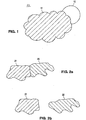
- Current z-ordering routines are limited to the reverse application; i. e. drawing an image frame after the z-ordering is known. For example, in Figure.1 there are three image regions to be drawn, a cloud, the sun, and the background regions 11 through 13 respectively. If the cloud has the z-ordering 1, the sun z-ordering 2, and the background, zordering 3, the image drawing routine knows to draw the background first, then the sun, and finally the cloud.
- This invention provides a method and apparatus as set out in the appended claims, for determining the relative z-ordering of the image regions in an image frame, given a sequence of image frames.
- This invention operates by understanding that with multiple frames, some portion of the hidden parts of the image regions may become visible, thus allowing the relative z-order of the different image regions.
- the basis of this invention is that by comparing two or more image regions that overlap in a particular image frame, with the same image regions in a different image frame where they do not overlap, it is possible to determine the relative z-ordering of the image regions. This is illustrated in Figure. 2a and 2b . Referring to Figure. 2a , there are two arbitrary image regions marked image region 21 and 22 respectively. Figure.
- FIG. 2a by itself does not contain enough information to determine which image region is occluding the other.
- FIG. 2b a second image frame, which shows the complete unoccluded image regions 21 and 22. It is apparent that image region 21 was partially occluding image region 22, in Figure. 2a .
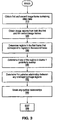
- Figure. 3 illustrates the overall flow diagram from the invention described herein.
- the invention obtains a first and second image frame containing video data.
- the invention obtains the image regions from both the first and second image frames.
- the image regions are segments.
- step 330 motion matching is performed on the image regions to determine corresponding image regions in the first and second image frame.
- Step 340 determines if any of the frame 1 image regions potentially overlap.
- Step 350 determines the pairwise relationship between any overlapping image regions.
- step 360 any cyclical relationships are broken. The invention ends at step 399.
- Figure. 4 illustrates how motion matching is used to determine the structure of the hidden image regions.
- Motion matching is the process of determining which image region, within an image frame, given a collection of image frames, most closely resembles the given image region.
- the invention uses motion matching to determine the structure of the hidden portions of the various image regions.
- Figure. 4a is composed of three image regions, the sun, the cloud, and the background marked image regions 41, 42 and 43, respectively.
- the sun is partially hidden behind the clouds.
- Figure. 4b is also composed of three image regions, the sun, the clouds, and the background marked image regions 44, 45 and 46, respectively.
- the sun is fully visible, i.e. not occluded by the cloud.
- the invention applies the matching routines and determines that image region 41, the sun in Figure. 4a , is matched with image region 44, the sun in Figure. 4b .
- the invention can determine more of the structure of image region 41, the partially hidden sun, to wit: since image region 41 and image region 44, represent the same collection of pixels.
- the hidden, unknown portions of image region 41 are identical to the corresponding visible portions of image region 44, therefore at least some of the previously unknown portions of image region 44 have been determined through the use of motion matching, (i.e. the newly visible portions of the image region)
- Figure. 6 illustrates the limitations of most traditional motion matching routines. Specifically, they are limited to the situations where an image region remains essentially the same, or the image region becomes less occluded, i.e. parts of the previously hidden portion of the image region becomes visible, without any of the visible portions becoming occluded. All other circumstances will confound most motion matching routines. This occurs because the motion matching routines do not have access to the newly hidden portions of the image region.
- Figure. 6a is composed of three image regions, the sun, clouds, and the background, marked image region 61 through 63, respectively.
- Figure. 6b is composed of three image regions, the sun, clouds, and the background. Unlike Figure. 6a , the cloud is partially blocking the sun in Figure. 6b . It is conceptually useful to consider image region 64, the sun in Figure. 6b , as two image sub-regions, sub-region 64a, the visible portion and sub-region 64b, the hidden portion. A sub-region is any subset of an image region.
- image region 61, the sun in Figure. 6a may be considered to be composed of sub-regions 61a and 61b, which respectively correspond to sub-regions 64a and 64b.
- Line 610 refers to the conceptual separation between sub-regions 61a and 61b.
- the matching routines can match the pixel values in sub-region 61 a with the pixel values in sub-region 64a. However, the remaining pixel values of image region 61, (i.e. sub-region 61b), will not be matched with the remaining pixel values in image region 64 (i.e. sub-region 64b) since those pixel values are hidden and therefore inaccessible to the matching routines.
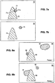
- Figure. 7 illustrates an alternative application of motion matching.
- a forward application of a motion matching routine will not match an image region with a subset of the same image region. However, the converse is not true.
- Most motion matching routines will match an image region with a superset of the image region.
- a superset of the image region refers to an image region, containing at least all of the pixels of the first image region.
- Figure. 7a which contains three image regions, the sun, a mountain, and the background, marked image regions 71 through 73, respectively, the rising sun, image region 71, is partially hidden behind the mountain.
- Figure. 7b also contains three image regions, the rising sun, the mountain, and the background, regions 74 through 76, respectively. The rising sun is no longer hidden behind the mountain.
- the partially hidden sun in Figure. 7a may be considered as 2 image sub-regions, the visible portion, and the hidden portion, sub-regions 71a and 71b respectively.
- the matching routine attempts to find a match for image region 71 in Figure. 7b , it can only consider the pixels in sub-region 71a as the pixels in sub-region 71b are hidden and therefore are not considered.
- each pixel in sub-region 71a has a corresponding pixel in region 74 and thus a match is found.
- the invention applies the matching routines backwards. That is, instead of matching from an image region in frame 1 to an image region in frame 2, the invention is given an image region from frame 2 and matches it with an image region in frame 1.
- Backward matching takes advantage of the fact that most motion matching algorithms will not match an image region with a subset of the image region as shown in figures 6a and 6b . However, most motion matching algorithms will match an image region with a superset of the same image region, as shown in Figures 7a and 7b .
- image regions which become more occluded, less occluded, or remain the same. Since image regions, which become more occluded, cannot be matched using forward motion matching methods, they must be matched using backwards matching. Image regions, which become less occluded or remain the same, may be matched using forward matching.
- the invention uses backwards motion matching to match the remaining image regions.
- image regions there are four image regions. These image regions, respectively designated regions 81 through 84, are a cloud, the sun, a mountain, and the background.
- regions 81 through 84 are a cloud, the sun, a mountain, and the background.
- frame 1 In frame 1, only the sun is partially occluded. However, in frame 2, the sun is no longer occluded, but the cloud is. Forward motion matching will match the mountain in both frames, as the mountain is unchanged. Additionally, the sun will be matched, as the sun in frame 1 is a subset of the sun in frame 2, i.e. the sun became less occluded in frame 2. However, the cloud will not be matched.
- Backward matching will attempt to match the unmatched cloud in frame 2 with an image region in frame 1. Since the frame 2 cloud is a subset of the frame 1 cloud, the matching routine, applied backwards, will designated the clouds as a match.
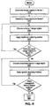
- the invention determines the image regions in frame 1. Similarly, at step 920, the frame 2 image regions are determined. At step 930, an image region from frame 1 is chosen and a traditional matching routine is applied at step 940. After matching, at step 950, the invention determines if there are any more frame 1 image regions to be matched. If so, then the routine proceeds to step 930, otherwise the invention continues at step 960 where an unmatched frame 2 image region is chosen. The new matching routines are applied backwards at step 970. At step 980, the invention determines if there are any more unmatched frame 2 image regions. If so, then the invention proceeds to step 960, otherwise the invention continues at step 999.
- Figure. 10 illustrates the method of error minimization.
- the invention computes the z-ordering information using a procedure known as error minimization.
- Error minimization is the process where the invention considers two image regions that overlap, given a collection of overlapping image regions within the same image frame, and determines which of the two image regions partially occludes the other. This results in a pairwise relationship between the two image regions. In this convention, the occluding image region has lower z-order than the occluded image region.
- Error minimization is applied to each pair of overlapping image regions within the collection of overlapping image regions. The objective is to create a sequence of pairwise relationships. These pairwise relationships can form either a transitive or cyclical relationship.
- a transitive relationship is one where, after all of the pairwise orders have been determined, all of the regions can be ordered along the z-axis and assigned relative depths. For example in Figure 10a if the pairwise relationships determined that image region 102 is on top of 103, 103 is on top of 101 and 102 is on top of 101, it is possible to determine that 102 is over 103 is over 101. This would be considered a transitive relation ship.
- the routine picks two image regions, which share common pixels. It computes the result of placing the first image region over the second image, then placing the second image region over the first image. The resulting two images are compared with the original image and the better match determines the pairwise relationship. In one embodiment the match is determined by comparing the two resulting images with the original image pixel by pixel and computing the lowest average error between the two images. In other embodiments of this invention, any other statistical parameter can be used as the criterion for determining the best match. The invention is also not limited to comparing only 2 image regions, it can consider any number of image regions at once.
- the invention starts with regions 101 and 102 and creates an image frame comprised of region 101 placed over region 102.
- the area 104 is an empty space or hole created by removing the triangle 102 rectangle 103 from Figure 10a frame 1.
- all subsequent steps assume that the background with all other regions removed, can still be matched with itself.
- the small part of triangle 102, visible from under 101 is marked 102a.
- the next image will be region 102 drawn over region 101, which yields a triangle on the background as illustrated in Figure 10c . Since region 102 over region 101 is the better match, region 102 has lower z-order than region 101.
- Figure. 10d illustrates the result of region 101 (the background) drawn over region 103 (the square). This yields the region 101 containing the above mentioned hole marked 104 and parts of 103 visible from underneath 101.
- Figure. 10e illustrated that drawing region 103 over region 101 yields the square and the background, which is the closer match to Figure. 10a .
- region 103 has a lower z-order than region 101.
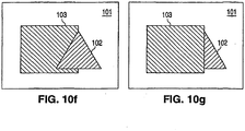
- the invention creates an image of region 102 placed over region 103, which yields the result seen in Figure. 10f . Then the invention creates an image, Figure. 10g , of region 103 placed over region 102. Region 102 over region 103 yields the better match to the first frame and thus region 102 has lower z-order than region 103. Putting the three image regions together we determined that region 102 has lower z-order than region 103 which has lower z-order than region 101. Since this relationship is a transitive relationship, region 102 occludes region 103 which occludes region 101 and the z-ordering is determined.
- the invention considers a group of image regions which overlap. Two image regions which overlap are chosen at step 1120.
- the routine applies error minimization, i.e. determining whether placing the first image region over the second is a closer match to the original image than placing the second image region over the first.
- Step 1140 uses the result of step 1130 to create a pairwise relationship between the two image regions.
- Step 1150 inquires if there are any more overlapping image regions. If so the invention jumps to step 1120, else it continues at step 1160.
- Step 1160 inquires if the pairwise relationships have formed a cyclical relationship (as explained fully in section 6). If so, the at step 1170, the cycle breaking routine at in Figure.
- step 15 is executed, otherwise the routine continues at step 1180, which uses the pairwise relationships to create the z-ordering.
- step 1190 the invention determines if there are any more groups of overlapping image regions. If so, the routine jumps to step 1110 and continues, else the invention ceases at step 1199.
- the pairwise relationship determines a transitive relationship as seen in Figure 12 , where region 121 is over region 122, region 122 is over region 123 and therefore we know that region 121 is over also region 123.
- Figure. 13 represents three image regions, as shown, region 131 a light grey circle, region 132, a dark black circle, region 133 a medium grey circle. For this illustration we ignore the background since its inclusion only needlessly complicates matters.
- the routine determines which pairwise relationship is the weakest.
- a pairwise relationship is considered weak when placing the first image region over the second image region and calculating the average error between this pair and the original image gives a similar value as placing the second image over the first and calculating the average error between this pair and the corresponding region-pairs in the original image.
- the pairwise relationship is considered weak. Therefore canceling the relationship does not significantly alter the final image.
- the invention cancels pairwise relationships beginning with the weakest, until the cyclical relationship is broken. In Figure. 13 , the pairwise relationship between image region 133 and 131 is the weakest.
- the invention considers a group of image regions with a cyclical relationship.
- the invention determines which pairwise relationship is the weakest. Step 1530 cancels the relationship.
- the invention determines if the cyclical relationship is broken. If yes, the invention returns at step 1599, else the invention returns to step 1520 and considers the next weakest pairwise relationship until all cyclical relationships have been broken.
Landscapes
- Engineering & Computer Science (AREA)
- Computer Vision & Pattern Recognition (AREA)
- Physics & Mathematics (AREA)
- General Physics & Mathematics (AREA)
- Theoretical Computer Science (AREA)
- Image Analysis (AREA)
- Image Processing (AREA)
- Testing, Inspecting, Measuring Of Stereoscopic Televisions And Televisions (AREA)
- Processing Or Creating Images (AREA)
- Apparatus For Radiation Diagnosis (AREA)
- Management, Administration, Business Operations System, And Electronic Commerce (AREA)
Abstract
Description
- The present invention relates in general to image processing, and in particular to identifying relative z-values between segments found in an image and using the relative overlap information in digital image processing.
- The solution disclosed herein is to determine the z-ordering information contained within a sequence of image frames that are temporally correlated. Z-ordering literally means to order by the "z", or depth axis. In other words, z-ordering means sequencing, or ordering, the image regions based upon how deep within the image frame they are. In this convention, z-ordering is measured from the viewer's perspective. Therefore, the further away an image region, or the deeper it is within an image frame, the higher the z-value of that region.
- Determining the z-order or depth of different regions of an image is very useful for applications such as digital image manipulations, image/video editing, video compression and various other digital image processing applications.
- In general, knowing the z-order of different objects within an image allows the video frames to be edited or manipulated because it now becomes possible to remove or add objects to this sequence of image frames without the loss of image integrity or image quality. Currently no methods exist that can satisfactorily identify the z-order of arbitrary objects within a temporally correlated image sequence.
- Z-ordering, as applied in this patent, represents an entirely new technology. There is currently no widely available technology that permits the determination of z-ordering information, from an arbitrarily chosen sequence of digital image frames, without human intervention. Current z-ordering routines are limited to the reverse application; i. e. drawing an image frame after the z-ordering is known. For example, in
Figure.1 there are three image regions to be drawn, a cloud, the sun, and thebackground regions 11 through 13 respectively. If the cloud has the z-ordering 1, the sun z-ordering 2, and the background, zordering 3, the image drawing routine knows to draw the background first, then the sun, and finally the cloud. - The paper entitled "Relative Depth Estimation of Video Objects for Image Interpretation" by Morier F et al, Proceedings of International Conference on Image Processing, ICIP 98, Vol. 1, 4-7 October 1998, pages 953 to 957 discloses a method to determine the relative depth of video objects and its use for region based interpolation. In particular, for each region of a segmented image at time t, the method estimates 2-dimensional motion between times t and t+1 and using this estimated motion projects each region of the segmented image to time t+1. This leads to overlapping areas that are then analysed in order to determine the local depth ordering of the overlap regions.
- This invention provides a method and apparatus as set out in the appended claims, for determining the relative z-ordering of the image regions in an image frame, given a sequence of image frames. This invention operates by understanding that with multiple frames, some portion of the hidden parts of the image regions may become visible, thus allowing the relative z-order of the different image regions. The basis of this invention is that by comparing two or more image regions that overlap in a particular image frame, with the same image regions in a different image frame where they do not overlap, it is possible to determine the relative z-ordering of the image regions. This is illustrated in
Figure. 2a and 2b . Referring toFigure. 2a , there are two arbitrary image regions markedimage region Figure. 2a by itself does not contain enough information to determine which image region is occluding the other. Referring toFigure. 2b , a second image frame, which shows the completeunoccluded image regions image region 21 was partially occludingimage region 22, inFigure. 2a . -
-
Figure 1 is an image frame containing three objects with known relative z-order. -
Figure 2a is an image frame containing two overlapping regions -
Figure 2b is an image frame where the two regions no longer overlap -
Figure 3 is a flowchart of a z-ordering process. -
Figures 4a and 4b illustrate how motion matching is used to determine the structure of hidden segments -
Figure 5 illustrate that motion matching is effective even when some parts of the two segments overlap. -
Figure 6a and 6b . illustrate a sequence of two image frames where traditional motion matching routines will fail to identify a particular region when it is partially occluded. -
Figures 7a and 7b illustrate a sequence of two image frames where traditional motion matching routines will successfully identify a particular region. -
Figure 8 is a sequence of two image frames where backward motion matching is to be applied. -
Figure 9 is a flow diagram of forward and forward and backward motion matching. -
Figures 10a -10g illustrate a process of pairwise comparisons of regions (segments). -
Figures 11 is a flow diagram of the process of error minimization. -
Figures 12 illustrate a transitive relationship. -
Figure 13a - 13g illustrate cycle breaking. -
Figures 14 .illustrate the restoration of transitive relationship after cycle breaking -
Figure 15 is a flow diagram of cycle breaking - With reference to the exemplary drawings wherein like reference numerals indicate like or corresponding elements among the figures, embodiments of a system according to the present invention will now be described in detail. It should be noted that the terms "segment" and "region" are used interchangeably herein.
-
Figure. 3 . illustrates the overall flow diagram from the invention described herein. Atstep 310, the invention obtains a first and second image frame containing video data. Atstep 320, the invention obtains the image regions from both the first and second image frames. In one embodiment of the invention, and without limitations to any other embodiments, the image regions are segments. - At
step 330, motion matching is performed on the image regions to determine corresponding image regions in the first and second image frame.Step 340 determines if any of theframe 1 image regions potentially overlap.Step 350 determines the pairwise relationship between any overlapping image regions. Atstep 360, any cyclical relationships are broken. The invention ends at step 399. -
Figure. 4 illustrates how motion matching is used to determine the structure of the hidden image regions. Motion matching is the process of determining which image region, within an image frame, given a collection of image frames, most closely resembles the given image region. The invention uses motion matching to determine the structure of the hidden portions of the various image regions. -
Figure. 4a is composed of three image regions, the sun, the cloud, and the background markedimage regions Figure. 4b is also composed of three image regions, the sun, the clouds, and the background markedimage regions Figure. 4b , unlikeFigure. 4a , the sun is fully visible, i.e. not occluded by the cloud. - The invention applies the matching routines and determines that
image region 41, the sun inFigure. 4a , is matched withimage region 44, the sun inFigure. 4b . Once the invention has made this determination, it can determine more of the structure ofimage region 41, the partially hidden sun, to wit: sinceimage region 41 andimage region 44, represent the same collection of pixels. The hidden, unknown portions ofimage region 41, are identical to the corresponding visible portions ofimage region 44, therefore at least some of the previously unknown portions ofimage region 44 have been determined through the use of motion matching, (i.e. the newly visible portions of the image region) - Further, the principle applies even if the sun in
Figure. 4b ,image region 42, remained partially occluded. For example, inFigure. 5 , there are three image regions, the sun, the clouds, and the background markedimage regions 51 through 53, respectively. As shown, the sun is partially hidden behind the clouds, although it is less hidden than inFigure. 4a . Applying a motion matching routine will matchimage region 41 withimage region 51. Once again, the hidden, unknown portions ofimage region 41 are identical to the corresponding portions ofimage region 51 which are visible. -
Figure. 6 illustrates the limitations of most traditional motion matching routines. Specifically, they are limited to the situations where an image region remains essentially the same, or the image region becomes less occluded, i.e. parts of the previously hidden portion of the image region becomes visible, without any of the visible portions becoming occluded. All other circumstances will confound most motion matching routines. This occurs because the motion matching routines do not have access to the newly hidden portions of the image region. -
Figure. 6a is composed of three image regions, the sun, clouds, and the background,marked image region 61 through 63, respectively.Figure. 6b is composed of three image regions, the sun, clouds, and the background. UnlikeFigure. 6a , the cloud is partially blocking the sun inFigure. 6b . It is conceptually useful to considerimage region 64, the sun inFigure. 6b , as two image sub-regions,sub-region 64a, the visible portion andsub-region 64b, the hidden portion. A sub-region is any subset of an image region. Similarly,image region 61, the sun inFigure. 6a , may be considered to be composed ofsub-regions sub-regions Line 610 refers to the conceptual separation betweensub-regions - The matching routines can match the pixel values in
sub-region 61 a with the pixel values insub-region 64a. However, the remaining pixel values ofimage region 61, (i.e.sub-region 61b), will not be matched with the remaining pixel values in image region 64 (i.e.sub-region 64b) since those pixel values are hidden and therefore inaccessible to the matching routines. - The consequence of the pixel values in
sub-region 64b being inaccessible to the matching routines is that most motion matching routines will rejectimage regions - Mathematically speaking, traditional motion matching routines will not match a region in
frame 1 to a subset, i.e. smaller portion, of the region infigure 2 . -
Figure. 7 . illustrates an alternative application of motion matching. As previously explained, a forward application of a motion matching routine will not match an image region with a subset of the same image region. However, the converse is not true. Most motion matching routines will match an image region with a superset of the image region. A superset of the image region, as used herein, refers to an image region, containing at least all of the pixels of the first image region. - Referring to
Figure. 7a , which contains three image regions, the sun, a mountain, and the background, markedimage regions 71 through 73, respectively, the rising sun,image region 71, is partially hidden behind the mountain. Similarly,Figure. 7b also contains three image regions, the rising sun, the mountain, and the background,regions 74 through 76, respectively. The rising sun is no longer hidden behind the mountain. - The partially hidden sun in
Figure. 7a may be considered as 2 image sub-regions, the visible portion, and the hidden portion,sub-regions image region 71 inFigure. 7b , it can only consider the pixels insub-region 71a as the pixels insub-region 71b are hidden and therefore are not considered. In the given example, each pixel insub-region 71a has a corresponding pixel inregion 74 and thus a match is found. - In one embodiment, the invention applies the matching routines backwards. That is, instead of matching from an image region in
frame 1 to an image region inframe 2, the invention is given an image region fromframe 2 and matches it with an image region inframe 1. - Backward matching takes advantage of the fact that most motion matching algorithms will not match an image region with a subset of the image region as shown in
figures 6a and 6b . However, most motion matching algorithms will match an image region with a superset of the same image region, as shown inFigures 7a and 7b . - As an image region moves from one frame to the next, it may become more occluded, less occluded, or remain the same. Since image regions, which become more occluded, cannot be matched using forward motion matching methods, they must be matched using backwards matching. Image regions, which become less occluded or remain the same, may be matched using forward matching.
- Thus, after the forward motion matching routines have identified the image regions, which do not become more occluded in
frame 2, the invention uses backwards motion matching to match the remaining image regions. - For example, as seen in
Figure 8 , there are four image regions. These image regions, respectively designatedregions 81 through 84, are a cloud, the sun, a mountain, and the background. Inframe 1, only the sun is partially occluded. However, inframe 2, the sun is no longer occluded, but the cloud is. Forward motion matching will match the mountain in both frames, as the mountain is unchanged. Additionally, the sun will be matched, as the sun inframe 1 is a subset of the sun inframe 2, i.e. the sun became less occluded inframe 2. However, the cloud will not be matched. - Backward matching will attempt to match the unmatched cloud in
frame 2 with an image region inframe 1. Since theframe 2 cloud is a subset of theframe 1 cloud, the matching routine, applied backwards, will designated the clouds as a match. - Referring to
Fig 9 , atstep 910 the invention determines the image regions inframe 1. Similarly, atstep 920, theframe 2 image regions are determined. Atstep 930, an image region fromframe 1 is chosen and a traditional matching routine is applied atstep 940. After matching, atstep 950, the invention determines if there are anymore frame 1 image regions to be matched. If so, then the routine proceeds to step 930, otherwise the invention continues atstep 960 where anunmatched frame 2 image region is chosen. The new matching routines are applied backwards atstep 970. At step 980, the invention determines if there are any moreunmatched frame 2 image regions. If so, then the invention proceeds to step 960, otherwise the invention continues atstep 999. -
Figure. 10 illustrates the method of error minimization. Once the image regions have been matched, the invention computes the z-ordering information using a procedure known as error minimization. Error minimization is the process where the invention considers two image regions that overlap, given a collection of overlapping image regions within the same image frame, and determines which of the two image regions partially occludes the other. This results in a pairwise relationship between the two image regions. In this convention, the occluding image region has lower z-order than the occluded image region. Error minimization is applied to each pair of overlapping image regions within the collection of overlapping image regions. The objective is to create a sequence of pairwise relationships. These pairwise relationships can form either a transitive or cyclical relationship. - When the pairwise relationships of a collection of overlapping image regions form a transitive relationship, then the z-ordering of the image regions is the same as the transitive relationship. A transitive relationship is one where, after all of the pairwise orders have been determined, all of the regions can be ordered along the z-axis and assigned relative depths. For example in
Figure 10a if the pairwise relationships determined thatimage region 102 is on top of 103, 103 is on top of 101 and 102 is on top of 101, it is possible to determine that 102 is over 103 is over 101. This would be considered a transitive relation ship. If on the contrary, the pairwise relationships determine that 102 is on top of 103, 103 is on top of 101 and 101 is on top of 102, this would create a cyclical relationship because it would not be possible to order these regions along a z-axis. When such a cyclical relationship occurs, the exact z-ordering cannot be determined, a method called cycle breaking is invoked to determine the z-ordering of the collection of image regions. The method of cycle breaking will be described in detail in a later section. - As described earlier
Figure. 10a , there are three image regions, the background, the triangle, and the square, respectivelymarked regions - In
Figure. 10b , the invention starts withregions region 101 placed overregion 102. Infigures 10b, c, d and e , thearea 104 is an empty space or hole created by removing thetriangle 102rectangle 103 fromFigure 10a frame 1. For the purposes of the description inFigure 10 , all subsequent steps assume that the background with all other regions removed, can still be matched with itself. The small part oftriangle 102, visible from under 101 is marked 102a. The next image will beregion 102 drawn overregion 101, which yields a triangle on the background as illustrated inFigure 10c . Sinceregion 102 overregion 101 is the better match,region 102 has lower z-order thanregion 101. - Next, the invention compares
regions Figure. 10d illustrates the result of region 101 (the background) drawn over region 103 (the square). This yields theregion 101 containing the above mentioned hole marked 104 and parts of 103 visible from underneath 101. Conversely,Figure. 10e illustrated that drawingregion 103 overregion 101 yields the square and the background, which is the closer match toFigure. 10a . Thus,region 103 has a lower z-order thanregion 101. - All that remains is to determine the pairwise relationship between
regions region 102 placed overregion 103, which yields the result seen inFigure. 10f . Then the invention creates an image,Figure. 10g , ofregion 103 placed overregion 102.Region 102 overregion 103 yields the better match to the first frame and thusregion 102 has lower z-order thanregion 103. Putting the three image regions together we determined thatregion 102 has lower z-order thanregion 103 which has lower z-order thanregion 101. Since this relationship is a transitive relationship,region 102 occludesregion 103 which occludesregion 101 and the z-ordering is determined. - Referring to
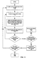
Fig. 11 , atstep 1110, the invention considers a group of image regions which overlap. Two image regions which overlap are chosen atstep 1120. Atstep 1130, the routine applies error minimization, i.e. determining whether placing the first image region over the second is a closer match to the original image than placing the second image region over the first.Step 1140 uses the result ofstep 1130 to create a pairwise relationship between the two image regions.Step 1150 inquires if there are any more overlapping image regions. If so the invention jumps to step 1120, else it continues atstep 1160.Step 1160 inquires if the pairwise relationships have formed a cyclical relationship (as explained fully in section 6). If so, the atstep 1170, the cycle breaking routine at inFigure. 15 is executed, otherwise the routine continues atstep 1180, which uses the pairwise relationships to create the z-ordering. Atstep 1190 the invention determines if there are any more groups of overlapping image regions. If so, the routine jumps to step 1110 and continues, else the invention ceases atstep 1199. - As explained previously, generally speaking, determining the pairwise relationships between the overlapping groups of image regions is sufficient to determine the z-ordering of the image regions. Generally, the pairwise relationship determines a transitive relationship as seen in
Figure 12 , whereregion 121 is overregion 122,region 122 is overregion 123 and therefore we know thatregion 121 is over alsoregion 123. - However, sometimes the situation in
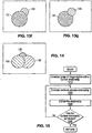
Figure 13 , occurs.Figure. 13 represents three image regions, as shown, region 131 a light grey circle,region 132, a dark black circle, region 133 a medium grey circle. For this illustration we ignore the background since its inclusion only needlessly complicates matters. - After applying the matching routines and the error minimization algorithms the results are the following pairwise relationships (See
Figures 13b-g ):image region 131 is overregion 132;region 132 is overregion 133 ; andregion 133 is overregion 131. Thus the image regions have a cyclical relationship as seen inFigure. 13a . - To turn this cyclical relationship into a transitive relationship so that the z-ordering can be obtained, the routine determines which pairwise relationship is the weakest. A pairwise relationship is considered weak when placing the first image region over the second image region and calculating the average error between this pair and the original image gives a similar value as placing the second image over the first and calculating the average error between this pair and the corresponding region-pairs in the original image. In other words, if the difference between the two said average errors is small the pairwise relationship is considered weak. Therefore canceling the relationship does not significantly alter the final image. The invention cancels pairwise relationships beginning with the weakest, until the cyclical relationship is broken. In
Figure. 13 , the pairwise relationship betweenimage region region 131 overregion 132;region 132 overregion 133. Thus a transitive relationship is formed and we know thatregion 131 is the closest to the viewer, i.e. has the lowest z-ordering,region 132 is deeper, having a higher z-ordering, andregion 133 is deeper still, having the highest z-ordering.Figure. 14 illustrates the resulting image, which is nearly identical toFigure. 13 . - Referring to
Figure. 15 , atstep 1510, the invention considers a group of image regions with a cyclical relationship. Atstep 1520, the invention determines which pairwise relationship is the weakest.Step 1530 cancels the relationship. - At
step 1540, the invention determines if the cyclical relationship is broken. If yes, the invention returns at step 1599, else the invention returns to step 1520 and considers the next weakest pairwise relationship until all cyclical relationships have been broken.
Claims (14)
- A method of determining local relative z-ordering information, the method comprising:(a) obtaining (310) a first image frame and second image frame containing digital image data;(b) dividing (320) the first image frame and second image frame into segments;(c) matching (330) segments of the first image frame to the second image frame, and matching segments of the second image frame to the first image frame;(d) determining relative offsets for the segments that represent a relative displacement of the segments between image frames;(e) determining (340) for either of the image frames which segments in that frame would overlap if the segments were moved by their relative offsets;(f) determining (1180), for segments that are determined from step (e) would overlap if moved by their relative offsets, a relative z-ordering; and(g) breaking (1170) any cyclical relationships,wherein the cyclical relationships are broken by obtaining a sequence of segments which share a cyclical z-ordering relationship, and cancelling (1520, 1530, 1540) a weakest relationship between segments until the cyclical relationship is broken.
- The method of claim 1, wherein segments are each of substantially uniform color and are embodied in a plurality of geometries and areas.
- The method of claim 1, wherein step (e) comprises considering groups of two or more matched segments which share a common boundary, the segments being matched using a forward (940) or backward (970) matching routine.
- The method of claim 1, wherein z-ordering relationships between segments are created (1180) by considering a plurality of segments in the first image frame which would overlap when moved by their relative offsets determined in step (d), placing segments over one another and comparing the results with the second image frame to calculate difference parameters, and determining z-ordering relationships from the difference parameters.
- The method of claim 4, wherein an error minimization technique is used.
- The method of claim 1, wherein the strength of a relationship between segments is based on a difference of average errors.
- The method of claim 1, wherein the strength of relationships between segments is based on any suitable statistical parameter.
- An apparatus for determining local relative z-ordering information, the apparatus comprising:(a) means for obtaining (310) a first image frame and second image frame containing digital image data;(b) means for dividing (320) the first image frame and second image frame into segments;(c) means for matching (330) segments of the first image frame to the second image frame, and for matching segments of the second image frame to the first image frame;(d) means for determining relative offsets for the segments that represent a relative displacement of the segments between image frames;(e) means for determining (340) for either of the image frames which segments in that frame would overlap if the segments were moved by their relative offsets;(f) means for determining (1180), for segments that are determined from means(e) would overlap if moved by their relative offsets, a relative z-ordering; and(g) means for breaking (1170) any cyclical relationships, by obtaining a sequence of segments which share a cyclical z-ordering relationship, and cancelling (1520, 1530, 1540) a weakest relationship between segments until the cyclical relationship is broken.
- The apparatus of claim 8, wherein segments are each of substantially uniform color and are embodied in a plurality of geometries and areas.
- The apparatus of claim 8, wherein said means (e) comprises means for considering groups of two or more matched segments which share a common boundary, the segments being matched using a forward (940) or backward (970) matching routine.
- The apparatus of claim 8, wherein said means (f) is operable to determine (1180) z-ordering relationships between segments by considering a plurality of segments in the first image frame which would overlap when moved by their relative offsets determined by means (d), by placing segments over one another, by comparing the results with the second image frame to calculate difference parameters, and by determining z-ordering relationships from the difference parameters.
- The apparatus of claim 11, wherein said means (f) is operable to use an error minimization technique.
- The apparatus of claim 8, wherein the strength of a relationship between segments is based on a difference of average errors.
- The apparatus of claim 8, wherein the strength of relationships between segments is based on any suitable statistical parameter.
Applications Claiming Priority (5)
| Application Number | Priority Date | Filing Date | Title |
|---|---|---|---|
| US22305700P | 2000-08-04 | 2000-08-04 | |
| US223057P | 2000-08-04 | ||
| US09/922,299 US6900802B2 (en) | 2000-08-04 | 2001-08-03 | Method of determining relative Z-ordering in an image and method of using same |
| US922299 | 2001-08-03 | ||
| PCT/US2001/024780 WO2002013127A1 (en) | 2000-08-04 | 2001-08-06 | Method of determining relative z-ordering in an image and method of using same |
Publications (3)
| Publication Number | Publication Date |
|---|---|
| EP1328895A1 EP1328895A1 (en) | 2003-07-23 |
| EP1328895A4 EP1328895A4 (en) | 2008-08-13 |
| EP1328895B1 true EP1328895B1 (en) | 2012-05-02 |
Family
ID=26917403
Family Applications (1)
| Application Number | Title | Priority Date | Filing Date |
|---|---|---|---|
| EP01963830A Expired - Lifetime EP1328895B1 (en) | 2000-08-04 | 2001-08-06 | Method of determining relative z-ordering in an image and method of using same |
Country Status (6)
| Country | Link |
|---|---|
| US (2) | US6900802B2 (en) |
| EP (1) | EP1328895B1 (en) |
| JP (1) | JP4698926B2 (en) |
| AT (1) | ATE556391T1 (en) |
| AU (1) | AU2001284750A1 (en) |
| WO (1) | WO2002013127A1 (en) |
Families Citing this family (4)
| Publication number | Priority date | Publication date | Assignee | Title |
|---|---|---|---|---|
| US20050231505A1 (en) * | 1998-05-27 | 2005-10-20 | Kaye Michael C | Method for creating artifact free three-dimensional images converted from two-dimensional images |
| US6909749B2 (en) | 2002-07-15 | 2005-06-21 | Pts Corporation | Hierarchical segment-based motion vector encoding and decoding |
| US7362374B2 (en) * | 2002-08-30 | 2008-04-22 | Altera Corporation | Video interlacing using object motion estimation |
| EP1524865A1 (en) * | 2003-10-17 | 2005-04-20 | Nederlandse Organisatie Voor Toegepast-Natuurwetenschappelijk Onderzoek Tno | Multi-plane display for displaying overlapping images |
Family Cites Families (11)
| Publication number | Priority date | Publication date | Assignee | Title |
|---|---|---|---|---|
| JPH02226376A (en) * | 1989-02-28 | 1990-09-07 | Fujitsu Ltd | Picture analyzing system |
| JPH02247781A (en) * | 1989-03-20 | 1990-10-03 | Fujitsu Ltd | Device for forming image-structured segment |
| US4980762A (en) * | 1989-10-13 | 1990-12-25 | Massachusetts Institute Of Technology | Method and apparatus for image processing to obtain three dimensional motion and depth |
| JP3359634B2 (en) * | 1991-10-10 | 2002-12-24 | ヒューレット・パッカード・カンパニー | Graphics output system with in-bounds update |
| US5874960A (en) | 1995-07-05 | 1999-02-23 | Microsoft Corporation | Method and system for sharing applications between computer systems |
| JPH09161074A (en) * | 1995-12-04 | 1997-06-20 | Matsushita Electric Ind Co Ltd | Picture processor |
| DE69726025T2 (en) * | 1996-06-13 | 2004-09-16 | K.U. Leuven Research & Development | METHOD AND DEVICE FOR OBTAINING A THREE-DIMENSIONAL SHAPE |
| US5892511A (en) | 1996-09-30 | 1999-04-06 | Intel Corporation | Method for assisting window selection in a graphical user interface |
| US6278466B1 (en) * | 1998-06-11 | 2001-08-21 | Presenter.Com, Inc. | Creating animation from a video |
| US6384826B1 (en) * | 1998-08-14 | 2002-05-07 | Xerox Corporation | Method, apparatus and computer medium for surface reconstruction by Voronoi filtering |
| JP2001320731A (en) * | 1999-11-26 | 2001-11-16 | Sanyo Electric Co Ltd | Device for converting two-dimensional image into there dimensional image and its method |
-
2001
- 2001-08-03 US US09/922,299 patent/US6900802B2/en not_active Expired - Fee Related
- 2001-08-06 WO PCT/US2001/024780 patent/WO2002013127A1/en active Application Filing
- 2001-08-06 AU AU2001284750A patent/AU2001284750A1/en not_active Abandoned
- 2001-08-06 AT AT01963830T patent/ATE556391T1/en active
- 2001-08-06 JP JP2002518410A patent/JP4698926B2/en not_active Expired - Fee Related
- 2001-08-06 EP EP01963830A patent/EP1328895B1/en not_active Expired - Lifetime
-
2005
- 2005-03-16 US US11/081,320 patent/US7429986B2/en not_active Expired - Fee Related
Also Published As
| Publication number | Publication date |
|---|---|
| US20020063706A1 (en) | 2002-05-30 |
| US20050156926A1 (en) | 2005-07-21 |
| WO2002013127A1 (en) | 2002-02-14 |
| EP1328895A1 (en) | 2003-07-23 |
| ATE556391T1 (en) | 2012-05-15 |
| US6900802B2 (en) | 2005-05-31 |
| US7429986B2 (en) | 2008-09-30 |
| JP4698926B2 (en) | 2011-06-08 |
| JP2004521405A (en) | 2004-07-15 |
| AU2001284750A1 (en) | 2002-02-18 |
| EP1328895A4 (en) | 2008-08-13 |
Similar Documents
| Publication | Publication Date | Title |
|---|---|---|
| Intille et al. | Disparity-space images and large occlusion stereo | |
| US6337917B1 (en) | Rule-based moving object segmentation | |
| Bobick et al. | Large occlusion stereo | |
| US8855408B2 (en) | Method and apparatus for recovering depth information of image | |
| US7379583B2 (en) | Color segmentation-based stereo 3D reconstruction system and process employing overlapping images of a scene captured from viewpoints forming either a line or a grid | |
| US5719954A (en) | Stereo matching method and disparity measuring method | |
| JP4074062B2 (en) | Semantic object tracking in vector image sequences | |
| EP0513047B1 (en) | Three-frame technique for analyzing two motions in successive image frames dynamically | |
| US9792719B2 (en) | Method and apparatus for removing outliers from a main view of a scene during 3D scene reconstruction | |
| JP4954206B2 (en) | Cut and paste video objects | |
| US6173077B1 (en) | Image segmentation | |
| US7512270B2 (en) | Method of image segmentation | |
| Zhang et al. | Stereo matching with segmentation-based cooperation | |
| US7429986B2 (en) | Method of determining relative z-ordering in an image and method of using same | |
| US20060104535A1 (en) | Method and apparatus for removing false edges from a segmented image | |
| US6687405B1 (en) | Image segmentation | |
| US7574038B1 (en) | Method and apparatus for determining the background of an image sequence | |
| EP3043315B1 (en) | Method and apparatus for generating superpixels for multi-view images | |
| JP2004508641A (en) | Digital image segmentation | |
| JP2004520660A (en) | Depth map calculation | |
| Okamoto et al. | Integration of color and range data for three-dimensional scene description | |
| Ye et al. | Estimating optical flow using a global matching formulation and graduated optimization | |
| CN114723688B (en) | Image processing method and system for CT image pneumonia recognition | |
| EP0992021B1 (en) | Method of detecting spatial gradient by utilizing color information | |
| Siu et al. | Hue feature-based stereo scheme for detecting half-occlusion and order reversal of objects |
Legal Events
| Date | Code | Title | Description |
|---|---|---|---|
| PUAI | Public reference made under article 153(3) epc to a published international application that has entered the european phase |
Free format text: ORIGINAL CODE: 0009012 |
|
| 17P | Request for examination filed |
Effective date: 20030224 |
|
| AK | Designated contracting states |
Designated state(s): AT BE CH CY DE DK ES FI FR GB GR IE IT LI LU MC NL PT SE TR |
|
| AX | Request for extension of the european patent |
Extension state: AL LT LV MK RO SI |
|
| RAP1 | Party data changed (applicant data changed or rights of an application transferred) |
Owner name: PTS CORPORATION |
|
| RAP1 | Party data changed (applicant data changed or rights of an application transferred) |
Owner name: ALTERA CORPORATION |
|
| A4 | Supplementary search report drawn up and despatched |
Effective date: 20080716 |
|
| RIC1 | Information provided on ipc code assigned before grant |
Ipc: G06T 7/00 20060101AFI20080710BHEP |
|
| 17Q | First examination report despatched |
Effective date: 20090213 |
|
| GRAP | Despatch of communication of intention to grant a patent |
Free format text: ORIGINAL CODE: EPIDOSNIGR1 |
|
| GRAS | Grant fee paid |
Free format text: ORIGINAL CODE: EPIDOSNIGR3 |
|
| GRAA | (expected) grant |
Free format text: ORIGINAL CODE: 0009210 |
|
| AK | Designated contracting states |
Kind code of ref document: B1 Designated state(s): AT BE CH CY DE DK ES FI FR GB GR IE IT LI LU MC NL PT SE TR |
|
| AX | Request for extension of the european patent |
Extension state: AL LT LV MK RO SI |
|
| REG | Reference to a national code |
Ref country code: GB Ref legal event code: FG4D |
|
| REG | Reference to a national code |
Ref country code: CH Ref legal event code: EP Ref country code: AT Ref legal event code: REF Ref document number: 556391 Country of ref document: AT Kind code of ref document: T Effective date: 20120515 |
|
| REG | Reference to a national code |
Ref country code: IE Ref legal event code: FG4D |
|
| REG | Reference to a national code |
Ref country code: DE Ref legal event code: R096 Ref document number: 60146510 Country of ref document: DE Effective date: 20120628 |
|
| REG | Reference to a national code |
Ref country code: NL Ref legal event code: T3 |
|
| REG | Reference to a national code |
Ref country code: LT Ref legal event code: MG9D Effective date: 20120502 |
|
| PG25 | Lapsed in a contracting state [announced via postgrant information from national office to epo] |
Ref country code: CY Free format text: LAPSE BECAUSE OF FAILURE TO SUBMIT A TRANSLATION OF THE DESCRIPTION OR TO PAY THE FEE WITHIN THE PRESCRIBED TIME-LIMIT Effective date: 20120502 Ref country code: SE Free format text: LAPSE BECAUSE OF FAILURE TO SUBMIT A TRANSLATION OF THE DESCRIPTION OR TO PAY THE FEE WITHIN THE PRESCRIBED TIME-LIMIT Effective date: 20120502 Ref country code: FI Free format text: LAPSE BECAUSE OF FAILURE TO SUBMIT A TRANSLATION OF THE DESCRIPTION OR TO PAY THE FEE WITHIN THE PRESCRIBED TIME-LIMIT Effective date: 20120502 |
|
| REG | Reference to a national code |
Ref country code: AT Ref legal event code: MK05 Ref document number: 556391 Country of ref document: AT Kind code of ref document: T Effective date: 20120502 |
|
| PG25 | Lapsed in a contracting state [announced via postgrant information from national office to epo] |
Ref country code: PT Free format text: LAPSE BECAUSE OF FAILURE TO SUBMIT A TRANSLATION OF THE DESCRIPTION OR TO PAY THE FEE WITHIN THE PRESCRIBED TIME-LIMIT Effective date: 20120903 Ref country code: GR Free format text: LAPSE BECAUSE OF FAILURE TO SUBMIT A TRANSLATION OF THE DESCRIPTION OR TO PAY THE FEE WITHIN THE PRESCRIBED TIME-LIMIT Effective date: 20120803 |
|
| PG25 | Lapsed in a contracting state [announced via postgrant information from national office to epo] |
Ref country code: BE Free format text: LAPSE BECAUSE OF FAILURE TO SUBMIT A TRANSLATION OF THE DESCRIPTION OR TO PAY THE FEE WITHIN THE PRESCRIBED TIME-LIMIT Effective date: 20120502 |
|
| PG25 | Lapsed in a contracting state [announced via postgrant information from national office to epo] |
Ref country code: AT Free format text: LAPSE BECAUSE OF FAILURE TO SUBMIT A TRANSLATION OF THE DESCRIPTION OR TO PAY THE FEE WITHIN THE PRESCRIBED TIME-LIMIT Effective date: 20120502 Ref country code: DK Free format text: LAPSE BECAUSE OF FAILURE TO SUBMIT A TRANSLATION OF THE DESCRIPTION OR TO PAY THE FEE WITHIN THE PRESCRIBED TIME-LIMIT Effective date: 20120502 |
|
| PG25 | Lapsed in a contracting state [announced via postgrant information from national office to epo] |
Ref country code: IT Free format text: LAPSE BECAUSE OF FAILURE TO SUBMIT A TRANSLATION OF THE DESCRIPTION OR TO PAY THE FEE WITHIN THE PRESCRIBED TIME-LIMIT Effective date: 20120502 |
|
| PLBE | No opposition filed within time limit |
Free format text: ORIGINAL CODE: 0009261 |
|
| STAA | Information on the status of an ep patent application or granted ep patent |
Free format text: STATUS: NO OPPOSITION FILED WITHIN TIME LIMIT |
|
| REG | Reference to a national code |
Ref country code: CH Ref legal event code: PL |
|
| PG25 | Lapsed in a contracting state [announced via postgrant information from national office to epo] |
Ref country code: MC Free format text: LAPSE BECAUSE OF NON-PAYMENT OF DUE FEES Effective date: 20120831 |
|
| 26N | No opposition filed |
Effective date: 20130205 |
|
| PG25 | Lapsed in a contracting state [announced via postgrant information from national office to epo] |
Ref country code: CH Free format text: LAPSE BECAUSE OF NON-PAYMENT OF DUE FEES Effective date: 20120831 Ref country code: LI Free format text: LAPSE BECAUSE OF NON-PAYMENT OF DUE FEES Effective date: 20120831 |
|
| REG | Reference to a national code |
Ref country code: FR Ref legal event code: ST Effective date: 20130430 |
|
| REG | Reference to a national code |
Ref country code: IE Ref legal event code: MM4A |
|
| REG | Reference to a national code |
Ref country code: DE Ref legal event code: R097 Ref document number: 60146510 Country of ref document: DE Effective date: 20130205 |
|
| PG25 | Lapsed in a contracting state [announced via postgrant information from national office to epo] |
Ref country code: IE Free format text: LAPSE BECAUSE OF NON-PAYMENT OF DUE FEES Effective date: 20120806 |
|
| PG25 | Lapsed in a contracting state [announced via postgrant information from national office to epo] |
Ref country code: FR Free format text: LAPSE BECAUSE OF NON-PAYMENT OF DUE FEES Effective date: 20120831 |
|
| PG25 | Lapsed in a contracting state [announced via postgrant information from national office to epo] |
Ref country code: ES Free format text: LAPSE BECAUSE OF FAILURE TO SUBMIT A TRANSLATION OF THE DESCRIPTION OR TO PAY THE FEE WITHIN THE PRESCRIBED TIME-LIMIT Effective date: 20120813 |
|
| PG25 | Lapsed in a contracting state [announced via postgrant information from national office to epo] |
Ref country code: TR Free format text: LAPSE BECAUSE OF FAILURE TO SUBMIT A TRANSLATION OF THE DESCRIPTION OR TO PAY THE FEE WITHIN THE PRESCRIBED TIME-LIMIT Effective date: 20120502 |
|
| PG25 | Lapsed in a contracting state [announced via postgrant information from national office to epo] |
Ref country code: LU Free format text: LAPSE BECAUSE OF NON-PAYMENT OF DUE FEES Effective date: 20120806 |
|
| PGFP | Annual fee paid to national office [announced via postgrant information from national office to epo] |
Ref country code: NL Payment date: 20150807 Year of fee payment: 15 |
|
| PGFP | Annual fee paid to national office [announced via postgrant information from national office to epo] |
Ref country code: DE Payment date: 20150831 Year of fee payment: 15 Ref country code: GB Payment date: 20150728 Year of fee payment: 15 |
|
| REG | Reference to a national code |
Ref country code: DE Ref legal event code: R119 Ref document number: 60146510 Country of ref document: DE |
|
| REG | Reference to a national code |
Ref country code: NL Ref legal event code: MM Effective date: 20160901 |
|
| GBPC | Gb: european patent ceased through non-payment of renewal fee |
Effective date: 20160806 |
|
| PG25 | Lapsed in a contracting state [announced via postgrant information from national office to epo] |
Ref country code: NL Free format text: LAPSE BECAUSE OF NON-PAYMENT OF DUE FEES Effective date: 20160901 |
|
| PG25 | Lapsed in a contracting state [announced via postgrant information from national office to epo] |
Ref country code: DE Free format text: LAPSE BECAUSE OF NON-PAYMENT OF DUE FEES Effective date: 20170301 Ref country code: GB Free format text: LAPSE BECAUSE OF NON-PAYMENT OF DUE FEES Effective date: 20160806 |