EP1328083A1 - Pre-distortion method for an MC-CDMA uplink - Google Patents
Pre-distortion method for an MC-CDMA uplink Download PDFInfo
- Publication number
- EP1328083A1 EP1328083A1 EP02290076A EP02290076A EP1328083A1 EP 1328083 A1 EP1328083 A1 EP 1328083A1 EP 02290076 A EP02290076 A EP 02290076A EP 02290076 A EP02290076 A EP 02290076A EP 1328083 A1 EP1328083 A1 EP 1328083A1
- Authority
- EP
- European Patent Office
- Prior art keywords
- matrix
- coefficients
- channel response
- carriers
- user
- Prior art date
- Legal status (The legal status is an assumption and is not a legal conclusion. Google has not performed a legal analysis and makes no representation as to the accuracy of the status listed.)
- Granted
Links
Images


Classifications
-
- H—ELECTRICITY
- H04—ELECTRIC COMMUNICATION TECHNIQUE
- H04B—TRANSMISSION
- H04B1/00—Details of transmission systems, not covered by a single one of groups H04B3/00 - H04B13/00; Details of transmission systems not characterised by the medium used for transmission
- H04B1/69—Spread spectrum techniques
- H04B1/707—Spread spectrum techniques using direct sequence modulation
-
- H—ELECTRICITY
- H04—ELECTRIC COMMUNICATION TECHNIQUE
- H04L—TRANSMISSION OF DIGITAL INFORMATION, e.g. TELEGRAPHIC COMMUNICATION
- H04L25/00—Baseband systems
- H04L25/02—Details ; arrangements for supplying electrical power along data transmission lines
- H04L25/03—Shaping networks in transmitter or receiver, e.g. adaptive shaping networks
- H04L25/03006—Arrangements for removing intersymbol interference
- H04L25/03343—Arrangements at the transmitter end
-
- H—ELECTRICITY
- H04—ELECTRIC COMMUNICATION TECHNIQUE
- H04L—TRANSMISSION OF DIGITAL INFORMATION, e.g. TELEGRAPHIC COMMUNICATION
- H04L27/00—Modulated-carrier systems
- H04L27/26—Systems using multi-frequency codes
- H04L27/2601—Multicarrier modulation systems
- H04L27/2647—Arrangements specific to the receiver only
-
- H—ELECTRICITY
- H04—ELECTRIC COMMUNICATION TECHNIQUE
- H04L—TRANSMISSION OF DIGITAL INFORMATION, e.g. TELEGRAPHIC COMMUNICATION
- H04L5/00—Arrangements affording multiple use of the transmission path
- H04L5/02—Channels characterised by the type of signal
- H04L5/023—Multiplexing of multicarrier modulation signals
- H04L5/026—Multiplexing of multicarrier modulation signals using code division
-
- H—ELECTRICITY
- H04—ELECTRIC COMMUNICATION TECHNIQUE
- H04L—TRANSMISSION OF DIGITAL INFORMATION, e.g. TELEGRAPHIC COMMUNICATION
- H04L25/00—Baseband systems
- H04L25/02—Details ; arrangements for supplying electrical power along data transmission lines
- H04L25/03—Shaping networks in transmitter or receiver, e.g. adaptive shaping networks
- H04L25/03006—Arrangements for removing intersymbol interference
- H04L2025/0335—Arrangements for removing intersymbol interference characterised by the type of transmission
- H04L2025/03375—Passband transmission
- H04L2025/03414—Multicarrier
-
- H—ELECTRICITY
- H04—ELECTRIC COMMUNICATION TECHNIQUE
- H04L—TRANSMISSION OF DIGITAL INFORMATION, e.g. TELEGRAPHIC COMMUNICATION
- H04L25/00—Baseband systems
- H04L25/02—Details ; arrangements for supplying electrical power along data transmission lines
- H04L25/03—Shaping networks in transmitter or receiver, e.g. adaptive shaping networks
- H04L25/03006—Arrangements for removing intersymbol interference
- H04L2025/03433—Arrangements for removing intersymbol interference characterised by equaliser structure
- H04L2025/03439—Fixed structures
- H04L2025/03445—Time domain
- H04L2025/03471—Tapped delay lines
- H04L2025/03484—Tapped delay lines time-recursive
Definitions
- the present invention relates to a method for uplink pre-distortion for a Multi-Carrier Code Division Multiple Access (MC-CDMA) telecommunication system.
- MC-CDMA Multi-Carrier Code Division Multiple Access
- Multi-Carrier Code Division Multiple Access combines OFDM (Orthogonal Frequency Division Multiplex) modulation and the CDMA multiple access technique.
- This multiple access technique was proposed for the first time by N. Yee et al. in the article entitled “Multicarrier CDMA in indoor wireless radio networks” which appeared in Proceedings of PIMRC'93, Vol. 1, pages 109-113, 1993. The developments of this technique were reviewed by S. Hara et al. in the article entitled “Overview of Multicarrier CDMA” published in IEEE Communication Magazine, pages 126-133, December 1997.
- the signature Unlike DS-CDMA (Direct Spread Code Division Multiple Access), in which the signal of each user is multiplied in the time domain in order to spread its frequency spectrum, the signature here multiplies the signal in the frequency domain, each element of the signature multiplying the signal of a different sub-carrier.
- DS-CDMA Direct Spread Code Division Multiple Access
- MC-CDMA combines the advantageous features of CDMA and OFDM, i.e. high spectral efficiency, multiple access capabilities, robustness in presence of frequency selective channels, high flexibility, narrow-band interference rejection, simple one-tap equalisation, etc.
- Fig. 1 illustrates the structure of an MC-CDMA transmitter for a given user i .
- the uplink i.e. we suppose that the transmitter is located in the mobile terminal (denoted MT) of a user i .
- the symbol d l ( n ) is first multiplied at 110 by the a spreading sequence (and a scrambling sequence which is here omitted for the sake of clarity) denoted c l ( t ).
- the spreading sequence consists of N "chips", each "chip” being of duration T c , the total duration of the spreading sequence corresponding to a symbol period T .
- T c duration of the spreading sequence corresponding to a symbol period T .
- a single spreading sequence is allocated to the user.
- a user may be allocated one or a plurality of orthogonal spreading sequences (multi-code allocation) according to the data rate required.
- the spreading allocated to different users are preferably chosen orthogonal.
- IFFT inverse fast Fourier transformation
- a guard interval of length typically greater than the duration of the impulse response of the transmission channel is added to the MC-CDMA symbol. This is achieved in practice by adding a prefix (denoted ⁇ ) identical to the end of the said symbol.
- the MC-CDMA symbols After being serialised in the parallel to serial converter 140, the MC-CDMA symbols are converted into an analogue signal which is then filtered and RF frequency up-converted (not shown) before being amplified in amplifier 150 and transmitted over the uplink transmission channel.
- the MC-CDMA method can essentially be regarded as a spreading in the spectral domain (before IFFT) followed by an OFDM modulation.
- MC-CDMA receiver for a given user i has been illustrated schematically in Fig. 2. Since we consider the uplink, the receiver is located at the base station.
- the signal is sampled at the "chip" frequency and the samples belonging to the guard interval are eliminated (elimination not shown).
- the signal obtained can be written: where where t takes successive sampling time values, K is the number of users and h l (l) represents the response of the channel of the user i to the frequency of the subcarrier l of the MC-CDMA symbol transmitted at time n.T and where b ( t ) is the received noise.
- the samples obtained by sampling the demodulated signal at the "chip" frequency are serial to parallel converted in 210 before undergoing an FFT in the module 220.
- the samples in the frequency domain, output from 220, are despread by the spreading sequence of user i .
- the samples of the frequency domain are multiplied by the coefficients c * / i (l) (here in the multipliers 230 0 ,.., 230 L-1 ) and then added (in adder 240).
- the summation result is detected in 250 for supplying an estimated symbol d and l .
- the detection may comprise an error correction decoding like a Viterbi or a turbo-decoding which are known as such.
- equalisation can be performed at the receiving side in order to compensate for the dispersive effects of the transmission channel.
- q l (l) 0,.., L -1 (here in 230 0 ,.., 230 L-1 ).
- there is no simple equalisation method for an uplink channel because the estimation of an uplink channel appears very complex.
- this estimation must be performed before despreading, i.e. at the chip level, when the signal from the different users are still combined.
- this estimation is usually performed after despreading, i.e. at the symbol level, and therefore separately for each user.
- pre-distortion at the transmitter side (i.e. in the mobile terminal, denoted MT), so that a simple demodulator could be used at the receiver side without needing to estimate the channel.
- the basic idea underlying pre-distortion is to exploit the reciprocity of the transmission channels (in TDD), that is the downlink channel estimation performed for the downlink demodulation is used as an estimation of the uplink channel. This implies both TDD-operation (same frequency band used for the uplink and downlink), and relatively low MT mobility, i.e. low Doppler frequency.
- An object of the present invention is to design a simple pre-distortion technique for an uplink channel in an MC-CDMA system which does not present the drawbacks set out above.
- the invention is defined by the pre-distortion method claimed in claim 1 and a transmitter implementing such pre-distortion method as claimed in claim 10.
- Advantageous embodiments of the invention are defined in the dependent claims.
- the basic idea underlying the invention stems from the analogy between the pre-distortion and the demodulation issues. In both cases, the channel selectivity destroys the orthogonality of the spreading sequences and orthogonality must be restored without unduly increasing the noise level (in the demodulation case), or without unduly increasing the transmitting power (in the pre-distortion case).
- c i , h i w i and ⁇ l are vectors of size N , where N is the spreading sequence length.
- N the spreading sequence length.
- the receiver of the base station simply demodulates the received signal by despreading it with each code sequence.
- the estimation of the symbol transmitted by the i h user can be expressed as: where ⁇ is a normalisation coefficient which for example represents the gain of the automatic gain control (AGC).
- AGC automatic gain control
- the interference term MAI i (due to the users j ⁇ i ) is equal to : whereas the useful term is equal to :
- the purpose of the invention is to find the vector w i of pre-distortion coefficients which maximises the value of , while minimising the interference MAI i and transmitted power P i .
- it is proposed to minimise a global mean square error taking into account all the users under the constraint of a fixed transmitted power for each user.
- the power control loop between the mobile terminal of user i and the base station ensures that the product of the transmitted power by the channel attenuation is maintained about a desired value which is the same for all the active users.
- the transmitted power is the same for all the users, e.g. equal to N (that is the average power of each carrier is chosen equal to 1) and that the channel attenuation is identical for all the channels.
- the error on the estimation d and l -d i can be obtained from (6) and (8):
- the global mean square error can be estimated:
- the first term of (15) can be rewritten as : where the Hermitian matrix ⁇ i is defined as :
- the Lagrange function is expressed as :
- equation (28) could provide a solution with a transmitted power slightly different from N .
- the transmitter does not know the value of parameter ⁇ .
- the transmitter of user i solves the linear system of equations (28) i.e. determines the unknown pre-distortion vector w i and normalises the result so that
- the value of the noise variance ⁇ 2 is taken here as the inverse of the SINR (Signal to Interference plus Noise Ratio) for the demodulated signal. It can be estimated by the base station and transmitted to the mobile terminal. Alternatively, a value of the noise variance ⁇ 2 can be retrieved from a look-up table of typical values stored e.g. in a memory of the mobile terminal. In general, the table is indexed by the parameters of the communication as the targeted BER level, the type of modulation, the type of channel coding used.
- the matrix ⁇ i for user i can be expressed as a function of the code sequences c j (for all the users j ) and channel response h i as follows: where . T denotes the transpose operation and Diag(u) denotes the diagonal matrix having the components of the vector u as diagonal elements. and therefore : where C is the NxK matrix of the code sequences.
- the calculation of ⁇ i merely entails a multiplication by diagonal matrices which requires few simple operations, and the calculation of the matrix C*C T for which fast algorithms, e.g. Fast Fourier Transform (FFT) or Walsh Hadamard Transform (WHT) do exist.
- FFT Fast Fourier Transform
- WHT Walsh Hadamard Transform
- the latter matrix needs only to be recalculated when the number of users or the code allocation changes, for example every frame.
- the matrix ⁇ i and hence the vector w i does not depend on the vectors of channel coefficients h j , j ⁇ i .
- the transmitter of the mobile terminal i simply needs to know the codes of the active users and the coefficients of the uplink channel for user i . As indicated above, the coefficients of the uplink channel are supposed identical to those of the downlink channel.
- Fig. 3 illustrates the structure of a MC-CDMA transmitter implementing the uplink pre-distortion method according to the invention.
- the transmitter comprises a first multiplier 310 for multiplying the symbol to be transmitted by the code sequence of user i, a multiplexer 320 for multiplexing the results over the OFDM multiplex, a module 330 performing an inverse Fourier transform (with prefix insertion), a parallel/serial converter 340 and an amplifier 350.
- ⁇ l (l) ⁇ N 2 K h * l (l) ⁇ . h l (l) 2 + N K ⁇ 2
- Fig. 4 illustrates the structure of a MC-CDMA receiver in the base station adapted to receive a signal transmitted by a MC-CDMA transmitter according to the invention.
- the present receiver comprises a serial to parallel converter 410, an FFT module 420 (with prefix removal), multipliers 430 0 to 430 L - l for multiplying the samples in the frequency domain by the conjugates c * / l (l) of the elements of the spreading sequence, an adder 440 and a detector 450 for supplying the estimated symbols.
- an error control decoding can be provided, like a Viterbi decoding or a turbo-decoding. In contrast to the prior art, however, no equalisation is needed since pre-distortion has been performed at the transmitter side.
- MC-CDMA transmitter illustrated in Fig. 3 has been described in terms of functional modules e.g. computing or estimating means, it goes without saying that all or part of this device can be implemented by means of a single processor either dedicated for performing all the functions depicted or in the form of a plurality of processors either dedicated or programmed for each performing one or some of said functions.
Abstract
Description
- The present invention relates to a method for uplink pre-distortion for a Multi-Carrier Code Division Multiple Access (MC-CDMA) telecommunication system.
- MC-CDMA has been receiving widespread interest for wireless broadband multimedia applications. Multi-Carrier Code Division Multiple Access (MC-CDMA) combines OFDM (Orthogonal Frequency Division Multiplex) modulation and the CDMA multiple access technique. This multiple access technique was proposed for the first time by N. Yee et al. in the article entitled "Multicarrier CDMA in indoor wireless radio networks" which appeared in Proceedings of PIMRC'93, Vol. 1, pages 109-113, 1993. The developments of this technique were reviewed by S. Hara et al. in the article entitled "Overview of Multicarrier CDMA" published in IEEE Communication Magazine, pages 126-133, December 1997.
- Unlike DS-CDMA (Direct Spread Code Division Multiple Access), in which the signal of each user is multiplied in the time domain in order to spread its frequency spectrum, the signature here multiplies the signal in the frequency domain, each element of the signature multiplying the signal of a different sub-carrier.
- In general, MC-CDMA combines the advantageous features of CDMA and OFDM, i.e. high spectral efficiency, multiple access capabilities, robustness in presence of frequency selective channels, high flexibility, narrow-band interference rejection, simple one-tap equalisation, etc.
- More specifically, Fig. 1 illustrates the structure of an MC-CDMA transmitter for a given user i. We consider here the uplink, i.e. we suppose that the transmitter is located in the mobile terminal (denoted MT) of a user i. Let d l (n) be the symbol to be transmitted from user i at time nT to the base station, where d l (n) belongs to the modulation alphabet. The symbol d l (n) is first multiplied at 110 by the a spreading sequence (and a scrambling sequence which is here omitted for the sake of clarity) denoted c l (t). The spreading sequence consists of N "chips", each "chip" being of duration Tc , the total duration of the spreading sequence corresponding to a symbol period T. Without loss of generality, we assume otherwise specified in the following that a single spreading sequence is allocated to the user. In general, a user may be allocated one or a plurality of orthogonal spreading sequences (multi-code allocation) according to the data rate required. In order to mitigate intra-cell interference, the spreading allocated to different users are preferably chosen orthogonal.
- The result of the multiplication of the symbol d l (n), hereinafter simply denoted di by the elements of the spreading sequence gives N symbols multiplexed in 120 over a subset of N frequencies of an OFDM multiplex. In general the number N of frequencies of said subset is a sub-multiple of the number L of frequencies of the OFDM multiplex. We assume in the following that L = N and denote cl (ℓ) = cl (ℓTc ), ℓ = 0,..,L-1 the values of the spreading sequence elements for user i. The block of symbols multiplexed in 120 is then subjected to an inverse fast Fourier transformation (IFFT) in the
module 130. In order to prevent intersymbol interference, a guard interval of length typically greater than the duration of the impulse response of the transmission channel, is added to the MC-CDMA symbol. This is achieved in practice by adding a prefix (denoted Δ) identical to the end of the said symbol. After being serialised in the parallel toserial converter 140, the MC-CDMA symbols are converted into an analogue signal which is then filtered and RF frequency up-converted (not shown) before being amplified inamplifier 150 and transmitted over the uplink transmission channel. The MC-CDMA method can essentially be regarded as a spreading in the spectral domain (before IFFT) followed by an OFDM modulation. - The signal Sl (t) at time t which is supplied to the amplifier before being transmitted over the reverse link transmission channel can therefore be written, if we omit the prefix:where f ℓ = (ℓ-L/2)/T, ℓ = 0,..,L-1 are the frequencies of the OFDM multiplex. More precisely, it should be understood that the transmitted signal is in fact Re(Sl (t)exp(j2πF 0 t)) where Re(.) stands for the real part and F0 is the RF carrier frequency. In other words, Sl (t) is the complex envelope of the transmitted signal.

- An MC-CDMA receiver for a given user i has been illustrated schematically in Fig. 2. Since we consider the uplink, the receiver is located at the base station.
- After baseband demodulation, the signal is sampled at the "chip" frequency and the samples belonging to the guard interval are eliminated (elimination not shown). The signal obtained can be written:where where t takes successive sampling time values, K is the number of users and hl (ℓ) represents the response of the channel of the user i to the frequency of the subcarrier ℓ of the MC-CDMA symbol transmitted at time n.T and where b(t) is the received noise.

- The samples obtained by sampling the demodulated signal at the "chip" frequency are serial to parallel converted in 210 before undergoing an FFT in the
module 220. The samples in the frequency domain, output from 220, are despread by the spreading sequence of user i. To do this, the samples of the frequency domain are multiplied by the coefficients c * / i (ℓ) (here in themultipliers 2300,.., 230L-1) and then added (in adder 240). The summation result is detected in 250 for supplying an estimated symbol d andl . Although not represented, the detection may comprise an error correction decoding like a Viterbi or a turbo-decoding which are known as such. - Furthermore, in MC-CDMA as in DS-CDMA, equalisation can be performed at the receiving side in order to compensate for the dispersive effects of the transmission channel. In MC-CDMA, the samples in the frequency domain are respectively multiplied with equalising coefficients ql (ℓ), ℓ = 0,..,L-1 (here in 2300,.., 230L-1). However, in MC-CDMA in contrast to DS-CDMA, there is no simple equalisation method for an uplink channel because the estimation of an uplink channel appears very complex.
- Indeed in MC-CDMA, this estimation must be performed before despreading, i.e. at the chip level, when the signal from the different users are still combined. In contrast, in DS-CDMA, this estimation is usually performed after despreading, i.e. at the symbol level, and therefore separately for each user.
- In order to overcome the problem of channel estimation, it has been proposed to implement a pre-distortion at the transmitter side (i.e. in the mobile terminal, denoted MT), so that a simple demodulator could be used at the receiver side without needing to estimate the channel. The basic idea underlying pre-distortion is to exploit the reciprocity of the transmission channels (in TDD), that is the downlink channel estimation performed for the downlink demodulation is used as an estimation of the uplink channel. This implies both TDD-operation (same frequency band used for the uplink and downlink), and relatively low MT mobility, i.e. low Doppler frequency.
- An MC-CDMA TDD-system with (downlink) pre-distortion has been described e.g. in the article of D.G. Jeong et al. entitled "Effects of channel estimation error in MC-CDMA/TDD systems" published in VTC 2000-Spring Tokyo, IEEE 51st, Vol. 3, pages 1773-1777. Pre-distortion is simply effected by multiplying each frequency component of the MC-CDMA symbol to be transmitted by the inverse of the channel response coefficient at said frequency, i.e. h -1 / l (ℓ). However, contrary to what is put forward in the above mentioned paper such downlink pre-distortion is not possible since the base station (denoted BS) cannot send one common pre-distorted multi-user signal which would have been optimised for the different propagation downlink channels from the base station to the mobile terminals (h -1 / l l (ℓ) depends on i). This problem does not exist for the uplink transmission channels and one could think to apply this pre-distortion technique for the uplink. However, multiplying the frequency components by the coefficients h -1 / l (ℓ) may lead to a very high transmitted power if the uplink transmission channel exhibits deep fades (i.e. hl (ℓ) may be close to zero for some subcarriers ℓ). This high transmitted power decreases in turn the battery autonomy and may significantly increase the interference towards adjacent cells.
- An object of the present invention is to design a simple pre-distortion technique for an uplink channel in an MC-CDMA system which does not present the drawbacks set out above.
- To this end, the invention is defined by the pre-distortion method claimed in
claim 1 and a transmitter implementing such pre-distortion method as claimed in claim 10. Advantageous embodiments of the invention are defined in the dependent claims. - The characteristics of the invention will emerge from a reading of the following description given in relation to the accompanying figures, amongst which:
- Fig. 1 depicts schematically the structure of an MC-CDMA transmitter known from the state of the art;
- Fig. 2 depicts schematically the structure of an MC-CDMA receiver known from the state of the art;
- Fig. 3 depicts schematically the structure of an MC-CDMA transmitter according to the invention;
- Fig. 4 depicts schematically the structure of an MC-CDMA receiver to be used with the MC-CDMA transmitter according to the invention.
-
- The basic idea underlying the invention stems from the analogy between the pre-distortion and the demodulation issues. In both cases, the channel selectivity destroys the orthogonality of the spreading sequences and orthogonality must be restored without unduly increasing the noise level (in the demodulation case), or without unduly increasing the transmitting power (in the pre-distortion case).
- We refer back to the context of an MC-CDMA TDD telecommunication system and more specifically to a base station receiving complex symbols from a plurality of active users i = 0,..,K-1. Let us denote, for user i, di the (complex scalar) transmitted symbol, c i the vector of components cl (ℓ), h i the channel response vector of components hl (ℓ), w i a pre-distortion vector of pre-distortion coefficients wl (ℓ) and ω l the corresponding vector of weighting coefficients ω l (ℓ) = w * / l (ℓ). In general, c i , h i w i and ω l are vectors of size N, where N is the spreading sequence length. As mentioned above, it is assumed that N=L, i.e. that the code sequence length is equal to the number of carriers and that one active user uses only one code sequence. However, the results set out below can be extended to the case where the number of carriers is greater than the spreading length (typically a multiple thereof) and/or to multi-code transmission.
- After FFT, the received signal can be expressed as (see equation 2) :where η is a vector of AWGN components of variance σ 2 and where ° expresses the vector multiplication element by element, that is (x ° y) k = xk .yk .

- The determination of the uplink channel responses being very difficult to achieve, the receiver of the base station simply demodulates the received signal by despreading it with each code sequence. The estimation of the symbol transmitted by the i h user can be expressed as:where µ is a normalisation coefficient which for example represents the gain of the automatic gain control (AGC). As the code sequences are assumed to be normalised, η i = c i / Hη has a variance equal to σ 2 .

- The expression (4) can be simplified by introducing a set of vectors ν ij where :The power used by the mobile terminal i for transmitting the symbol di can be expressed as:
 whereas the useful term is equal to :

- The purpose of the invention is to find the vector w i of pre-distortion coefficients which maximises the value of, while minimising the interference MAIi and transmitted power Pi . According to the invention, it is proposed to minimise a global mean square error taking into account all the users under the constraint of a fixed transmitted power for each user. The power control loop between the mobile terminal of user i and the base station ensures that the product of the transmitted power by the channel attenuation is maintained about a desired value which is the same for all the active users. Without loss of generality, we may equivalently suppose in the following that the transmitted power is the same for all the users, e.g. equal to N (that is the average power of each carrier is chosen equal to 1) and that the channel attenuation is identical for all the channels. Let us consider the cost function:


- The problem of minimisation under constraint mentioned above amounts to finding the minimum of the Lagrange function :where the λ i are the Lagrange scalar multipliers.

- The error on the estimation d andl-di can be obtained from (6) and (8):The coefficient µ has to be optimised: for normalised transmission and channels, the amplitude of the useful part will depend on the pre-distortion method, and be equal to 1 only for w l = h i . A bias will therefore be introduced, and must be compensated by AGC before calculation of the square error.

From (12), the global mean square error can be estimated:
 The first term of (15) can be rewritten as :
 where the Hermitian matrix Φ i is defined as :
 Finally, the Lagrange function is expressed as :

- By calculating the gradients according to the vectors w * / i = ω i (the same result is obtained by calculating the gradients according to vector w i ), the following set of equations is obtained :By replacing ν ii with h i /N :
 where I is the identity matrix of size NxN.
At that stage, parameters λ i and µ remain to be determined. Derivingaccording to parameter µ provides a new equation : By combining equations (20) and (21), we obtain :
 Furthermore, by multiplying on the left each term of equation (20) by w H / i, we obtain :
 Since the transmitted power |w i |2 is assumed to be equal to N :
 where
where
λ is the average value of the Lagrange multipliers λ i .
The average valueλ can therefore be expressed as :λ . Equation (20) then becomes :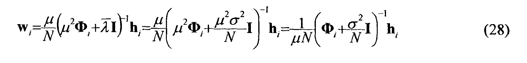
- Due to the above approximation, equation (28) could provide a solution with a transmitted power slightly different from N. In addition, the transmitter does not know the value of parameter µ. In practice, the transmitter of user i solves the linear system of equations (28) i.e. determines the unknown pre-distortion vector w i and normalises the result so that |w i | 2 is equal to N. Therefore,where the real coefficient α corresponds to the normalisation of w i .

- Equivalently, instead of inverting the matrixand where wi (ℓ) are the unknown coefficients, can be solved. The pre-distortion coefficients wi (ℓ) are then normalised as set out above. The weighting coefficients are then obtained from ω l (ℓ) =w * / i (ℓ).

- Because of the presence of the matrix σ2 / N I in expression (29) the pre-distortion coefficients wl (ℓ) are bounded even if a deep fade is experienced on the transmission channel. The value of the noise variance σ2 is taken here as the inverse of the SINR (Signal to Interference plus Noise Ratio) for the demodulated signal. It can be estimated by the base station and transmitted to the mobile terminal. Alternatively, a value of the noise variance σ2 can be retrieved from a look-up table of typical values stored e.g. in a memory of the mobile terminal. In general, the table is indexed by the parameters of the communication as the targeted BER level, the type of modulation, the type of channel coding used.
- The matrix Φ i for user i can be expressed as a function of the code sequences c j (for all the users j) and channel response h i as follows:
 where .T denotes the transpose operation and Diag(u) denotes the diagonal matrix having the components of the vector u as diagonal elements.
 and therefore :
 where C is the NxK matrix of the code sequences.
- As it can be seen from expression (33), the calculation of Φ i merely entails a multiplication by diagonal matrices which requires few simple operations, and the calculation of the matrix C*C T for which fast algorithms, e.g. Fast Fourier Transform (FFT) or Walsh Hadamard Transform (WHT) do exist. The latter matrix needs only to be recalculated when the number of users or the code allocation changes, for example every frame. It is important to note that the matrix Φ i and hence the vector w i does not depend on the vectors of channel coefficients h j , j≠i. The transmitter of the mobile terminal i simply needs to know the codes of the active users and the coefficients of the uplink channel for user i. As indicated above, the coefficients of the uplink channel are supposed identical to those of the downlink channel.
- Fig. 3 illustrates the structure of a MC-CDMA transmitter implementing the uplink pre-distortion method according to the invention. As in the prior art, the transmitter comprises a
first multiplier 310 for multiplying the symbol to be transmitted by the code sequence of user i, amultiplexer 320 for multiplexing the results over the OFDM multiplex, amodule 330 performing an inverse Fourier transform (with prefix insertion), a parallel/serial converter 340 and anamplifier 350. In contrast with the prior art however, the transmitter further comprises asecond multiplier 311 for multiplying the frequency components dlcl (ℓ) with the weighting coefficients ω i (ℓ) = w * / i(ℓ) respectively. Achannel estimation module 360 estimates, e.g. from a received signal corresponding to a pilot symbol transmitted by the base station, the channel coefficients hl (ℓ). From these coefficients and the knowledge of the code sequences allocated to the K active users, the matrix Φ i is calculated inmodule 361 according to equation (33). From the matrix Φ i , the vector h i and a value of noise variance σ2 themodule 362 determines the pre-distortion coefficients wl (ℓ) according to expression (29) and then the weighting coefficients ω l (ℓ) = w * / l(ℓ). - According to a first variant of the invention shown below, the calculation of the matrix Φ i in
module 361 can be made in the real domain. Indeed, if hl (ℓ)=ρ l (ℓ)ej i(ℓ) where ρ l (ℓ) and l (ℓ) are respectively the amplitude and the argument of the channel response coefficient hi (ℓ), and we denote ρ l and e ji the vectors of components ρ l (ℓ) and ejl (ℓ) respectively, we have:where we have denoted: From equation (34) we obtain:


 Hence,
 where
where
- A second variant of the invention is described hereafter. First, it is assumed that the MC-CDMA operates at full load and the code sequences are orthogonal or quasi-orthogonal. In such instance the matrix C*C T is equal to the identity matrix and (33) then becomes:By replacing the expression (37) into (29), we obtain for the full load case a pre-distortion vector of components wl (ℓ):

- When the system does not operate at full load, the matrix C * C T is not equal to the identity matrix anymore but the diagonal terms remain predominant. Indeed, the diagonal terms are equal to :and are expected to be larger than the off-diagonal terms
 since the terms C * / kj Ck ' j tend to cancel out each other when k ≠ k'. By approximating the matrix C*C T to its diagonal terms, we obtain:
 Finally, by replacing expression (41) into (29), the components of the pre-distortion vector, can be approximated as follows:
 where α is a normalisation factor. That is, the weighting coefficients ω l (ℓ) are expressed as:
- In addition, it can be shown that, if the channel response coefficients hl (ℓ), ℓ = 0,..,L-1 are correlated, the MAI level is reduced and the following expression for the weighting coefficients is advantageously used:
- Fig. 4 illustrates the structure of a MC-CDMA receiver in the base station adapted to receive a signal transmitted by a MC-CDMA transmitter according to the invention. As in the prior art of Fig. 2, the present receiver comprises a serial to
parallel converter 410, an FFT module 420 (with prefix removal), multipliers 4300 to 430 L - l for multiplying the samples in the frequency domain by the conjugates c * / l (ℓ) of the elements of the spreading sequence, anadder 440 and adetector 450 for supplying the estimated symbols. As in the prior art, an error control decoding can be provided, like a Viterbi decoding or a turbo-decoding. In contrast to the prior art, however, no equalisation is needed since pre-distortion has been performed at the transmitter side. - Although the MC-CDMA transmitter illustrated in Fig. 3 has been described in terms of functional modules e.g. computing or estimating means, it goes without saying that all or part of this device can be implemented by means of a single processor either dedicated for performing all the functions depicted or in the form of a plurality of processors either dedicated or programmed for each performing one or some of said functions.
Claims (10)
- Pre-distortion method for a telecommunication system comprising a base station and at least one user (i), each symbol (dl ) of said user being spread with a coding sequence (cl (ℓ)) over a plurality of carriers (ℓ) to produce a plurality of corresponding frequency components (dlcl (ℓ)) of a signal (Si (t)) to be transmitted over an uplink transmission channel to said base station, characterised in that each of said frequency components is weighted by a weighting coefficient (ω l (ℓ)), said weighting coefficients being a function of the channel response coefficients (hl (ℓ)) of the corresponding downlink transmission channel at the frequencies (f ℓ) of said carriers and of a value of the noise variance (σ2) affecting said carriers.
- Pre-distortion method according to claim 1, characterised in that, for said user (i), a vector ω i representing said weighting coefficients is determined from a vector h i representing said channel response coefficients as the conjugate of a vector w l , the latter vector being obtained from an expression of the type
- Pre-distortion method according to claim 2, characterised in that said matrix Φ i is calculated according to an expression of the typewhere
 and
and are diagonal matrices having respectively said channel response coefficients and the conjugates thereof as diagonal elements,
 and
and are diagonal matrices having respectively the elements of the coding sequence of said user and the conjugates thereof as diagonal elements, C is a matrix representing the code sequences allocated to the active users, and where .* and . T respectively denote the conjugate and the transpose operations.
- Pre-distortion method according to claim 2, characterised in that said matrix Φ i is calculated according to an expression of the typewhere K is the number of active users and
 is a diagonal matrix having the square modulus of said channel response coefficients as diagonal elements.
- Pre-distortion method according to claim 1, characterised in that said weighting coefficients ω i (ℓ) of the frequency components relative to the carriers ℓ are proportional to
- Pre-distortion method according to claim 1, characterised in that for said user (i), a vector ω' i representing the respective amplitudes of said weighting coefficients is determined from a vector ρ i representing the respective amplitudes of said channel response coefficients, according to an expression of the type
- Pre-distortion method according to claim 6, characterised in that said matrix Φ ' / l is calculated according to an expression of the typewhere
 is a diagonal matrix having the components of said vector ρ i as diagonal elements,
 and
and are diagonal matrices having respectively the elements of the coding sequence of said user and the conjugates thereof as diagonal elements, C is a matrix representing the code sequences allocated to the active users, .* and .T respectively denote the conjugate and the transpose operations.
- Pre-distortion method according to any preceding claim, characterised in that said value of noise variance is retrieved from a look-up table.
- Pre-distortion method according to any of claims 1-7, characterised in that said value of the noise variance is a measured value transmitted by said base station.
- Transmitter for a mobile terminal of an MC-CDMA telecommunication system comprising spreading means (310) for spreading a symbol (di ) to be transmitted over a plurality of carriers (ℓ) to produce a plurality of frequency components (dlci (ℓ)), characterised by estimating means (360) for estimating the channel response coefficients (hl (ℓ)) of the downlink transmission channel at the frequencies (f ℓ) of said carriers, calculating means (361, 362) deriving from said channel response coefficients and a value of the noise variance (σ2) affecting said carriers, a plurality of weighting coefficients (ω l (ℓ)), and weighting means (311) for weighting said frequency components with said weighting coefficients.
Priority Applications (5)
| Application Number | Priority Date | Filing Date | Title |
|---|---|---|---|
| AT02290076T ATE343880T1 (en) | 2002-01-11 | 2002-01-11 | PREDISTORTION METHOD FOR A MULTI CARRIER CDMA UPCHANNEL |
| DE60215608T DE60215608T2 (en) | 2002-01-11 | 2002-01-11 | Predistortion method for a multicarrier CDMA upstream channel |
| EP02290076A EP1328083B1 (en) | 2002-01-11 | 2002-01-11 | Pre-distortion method for an MC-CDMA uplink |
| US10/335,898 US7315530B2 (en) | 2002-01-11 | 2003-01-03 | Pre-distortion method for telecommunication system and transmitter for mobile terminal of MC-CDMA telecommunication system |
| JP2003003372A JP4250739B2 (en) | 2002-01-11 | 2003-01-09 | Predistortion method for communication system and transmitter for portable terminal of MC-CDMA communication system |
Applications Claiming Priority (1)
| Application Number | Priority Date | Filing Date | Title |
|---|---|---|---|
| EP02290076A EP1328083B1 (en) | 2002-01-11 | 2002-01-11 | Pre-distortion method for an MC-CDMA uplink |
Publications (2)
| Publication Number | Publication Date |
|---|---|
| EP1328083A1 true EP1328083A1 (en) | 2003-07-16 |
| EP1328083B1 EP1328083B1 (en) | 2006-10-25 |
Family
ID=8185699
Family Applications (1)
| Application Number | Title | Priority Date | Filing Date |
|---|---|---|---|
| EP02290076A Expired - Lifetime EP1328083B1 (en) | 2002-01-11 | 2002-01-11 | Pre-distortion method for an MC-CDMA uplink |
Country Status (5)
| Country | Link |
|---|---|
| US (1) | US7315530B2 (en) |
| EP (1) | EP1328083B1 (en) |
| JP (1) | JP4250739B2 (en) |
| AT (1) | ATE343880T1 (en) |
| DE (1) | DE60215608T2 (en) |
Families Citing this family (17)
| Publication number | Priority date | Publication date | Assignee | Title |
|---|---|---|---|---|
| JP3877215B2 (en) * | 2003-10-10 | 2007-02-07 | 株式会社インテリジェント・コスモス研究機構 | Transmission device, communication system, and communication method |
| JP2005269392A (en) * | 2004-03-19 | 2005-09-29 | Nec Electronics Corp | Receiving device, receiving method, and communication system and device |
| JP4546145B2 (en) * | 2004-05-11 | 2010-09-15 | モトローラ・インコーポレイテッド | Multi-carrier transmission system and multi-carrier transmission receiver |
| US8218694B2 (en) * | 2004-08-03 | 2012-07-10 | Agency For Science, Technology And Research | Method for transmitting a digital signal, method for receiving a digital signal, transmitter and receiver |
| KR20070055527A (en) * | 2004-09-08 | 2007-05-30 | 마츠시타 덴끼 산교 가부시키가이샤 | Wireless transmitting apparatus and pre-equalization method thereof |
| US7715460B2 (en) | 2005-04-22 | 2010-05-11 | Interdigital Technology Corporation | Hybrid orthogonal frequency division multiple access system and method |
| KR101218495B1 (en) * | 2006-02-21 | 2013-01-18 | 삼성전자주식회사 | An adaptive channel prediction apparatus and method for uplink pre-equalization in mobile communication system using orthgonal frequncy division multiplexing/time division duplex according to the quantity of downlink channel variation |
| FR2897734A1 (en) * | 2006-02-23 | 2007-08-24 | France Telecom | Digital signal space division multiplexing performing method for e.g. orthogonal frequency division multiplexed transmitter, involves determining power set transmitted by sub-groups of sub-carriers by minimizing overall-error criteria |
| US8019015B2 (en) * | 2007-02-26 | 2011-09-13 | Harris Corporation | Linearization of RF power amplifiers using an adaptive subband predistorter |
| US8099132B2 (en) * | 2007-08-15 | 2012-01-17 | Qualcomm Incorporated | Antenna switching and uplink sounding channel measurement |
| JP5096208B2 (en) * | 2008-03-26 | 2012-12-12 | パナソニック株式会社 | SC-FDMA transmitter and SC-FDMA transmission signal forming method |
| US8798471B2 (en) | 2009-10-13 | 2014-08-05 | Xieon Networks S.A.R.L. | Method for processing data in an optical network element and optical network element |
| US9363068B2 (en) | 2010-08-03 | 2016-06-07 | Intel Corporation | Vector processor having instruction set with sliding window non-linear convolutional function |
| WO2012092647A1 (en) * | 2011-01-04 | 2012-07-12 | James Cook University | A method and system for linearising a radio frequency transmitter |
| US20130235956A1 (en) * | 2012-03-09 | 2013-09-12 | Qual Comm Incorporated | Stability control in signal detection through code and time domain conditioning |
| US9300333B2 (en) * | 2014-08-01 | 2016-03-29 | Apple Inc. | Methods for computing predistortion values for wireless systems |
| WO2017161478A1 (en) * | 2016-03-21 | 2017-09-28 | 中国科学技术大学 | Method for transmitting signals to multiple users by using wireless channel reciprocity |
Citations (1)
| Publication number | Priority date | Publication date | Assignee | Title |
|---|---|---|---|---|
| WO1999052250A1 (en) * | 1998-04-03 | 1999-10-14 | Tellabs Operations, Inc. | Filter for impulse response shortening, with addition spectral constraints, for multicarrier transmission |
Family Cites Families (21)
| Publication number | Priority date | Publication date | Assignee | Title |
|---|---|---|---|---|
| US5872814A (en) * | 1997-02-24 | 1999-02-16 | At&T Wireless Services Inc. | Method for linearization of RF transmission electronics using baseband pre-distortion in T/R compensation pilot signals |
| US6298096B1 (en) * | 1998-11-19 | 2001-10-02 | Titan Corporation | Method and apparatus for determination of predistortion parameters for a quadrature modulator |
| US6118335A (en) * | 1999-05-06 | 2000-09-12 | Nortel Networks Corporation | Method and apparatus for providing adaptive predistortion in power amplifier and base station utilizing same |
| WO2000074232A1 (en) * | 1999-05-28 | 2000-12-07 | Fujitsu Limited | Predistortion type distortion compensation amplifier |
| US6356146B1 (en) * | 1999-07-13 | 2002-03-12 | Pmc-Sierra, Inc. | Amplifier measurement and modeling processes for use in generating predistortion parameters |
| AU755728B2 (en) * | 1999-12-28 | 2002-12-19 | Ntt Docomo, Inc. | Path search method, channel estimating method and communications device |
| US6817412B2 (en) * | 2000-01-24 | 2004-11-16 | Shell Oil Company | Method and apparatus for the optimal predistortion of an electromagnetic signal in a downhole communication system |
| CN1193563C (en) * | 2000-02-22 | 2005-03-16 | 皇家菲利浦电子有限公司 | Multicarrier receiver with channel estimator |
| SG108240A1 (en) * | 2000-02-23 | 2005-01-28 | Ntt Docomo Inc | Multi-carrier cdma radio transmitting method and apparatus, and channel estimation method and apparatus for multi-carrier cdma radio transmitting system |
| GB0004125D0 (en) * | 2000-02-23 | 2000-04-12 | Koninkl Philips Electronics Nv | Communications system |
| DE10012538C1 (en) * | 2000-03-15 | 2001-09-20 | Fraunhofer Ges Forschung | Digital I/Q modulator with pre-distortion, e.g. for broadcast radio transmitter, forms I and Q pre-distortion components from difference between I and Q signals and additional pre-distortion values |
| US6952561B1 (en) * | 2000-08-31 | 2005-10-04 | Lucent Technologies Inc. | Enhanced metric for bit detection on fading channels with unknown statistics |
| CA2361247C (en) * | 2000-11-06 | 2008-10-07 | Ntt Docomo, Inc. | Transmitter, transmitting method, receiver, and receiving method for mc-cdma communication system |
| FR2818057B1 (en) * | 2000-12-13 | 2006-07-07 | Mitsubishi Electric Inf Tech | METHOD AND DEVICE FOR MULTI-USER DETECTION |
| US7035345B2 (en) * | 2001-06-08 | 2006-04-25 | Polyvalor S.E.C. | Adaptive predistortion device and method using digital receiver |
| US6498529B1 (en) * | 2001-06-08 | 2002-12-24 | Lucent Technologies Inc. | Method and apparatus for calculating the predistortion function from a power amplifier |
| US7027523B2 (en) * | 2001-06-22 | 2006-04-11 | Qualcomm Incorporated | Method and apparatus for transmitting data in a time division duplexed (TDD) communication system |
| US6794936B2 (en) * | 2001-07-03 | 2004-09-21 | Lucent Technologies Inc. | Equalizer system and method for predistortion |
| US6931080B2 (en) * | 2001-08-13 | 2005-08-16 | Lucent Technologies Inc. | Multiple stage and/or nested predistortion system and method |
| EP1453229A4 (en) * | 2001-08-30 | 2007-07-11 | Fujitsu Ltd | Multi-carrier cdma transmission system and transmission method |
| US7058369B1 (en) * | 2001-11-21 | 2006-06-06 | Pmc-Sierra Inc. | Constant gain digital predistortion controller for linearization of non-linear amplifiers |
-
2002
- 2002-01-11 AT AT02290076T patent/ATE343880T1/en not_active IP Right Cessation
- 2002-01-11 DE DE60215608T patent/DE60215608T2/en not_active Expired - Lifetime
- 2002-01-11 EP EP02290076A patent/EP1328083B1/en not_active Expired - Lifetime
-
2003
- 2003-01-03 US US10/335,898 patent/US7315530B2/en not_active Expired - Fee Related
- 2003-01-09 JP JP2003003372A patent/JP4250739B2/en not_active Expired - Fee Related
Patent Citations (1)
| Publication number | Priority date | Publication date | Assignee | Title |
|---|---|---|---|---|
| WO1999052250A1 (en) * | 1998-04-03 | 1999-10-14 | Tellabs Operations, Inc. | Filter for impulse response shortening, with addition spectral constraints, for multicarrier transmission |
Non-Patent Citations (4)
| Title |
|---|
| CACOPARDI: "Combined OFDM-CDMA configurations for multimedia wireless applications", IEEE TRANSACTIONS ON CONSUMER ELECTRONICS, vol. 42, no. 4, November 1996 (1996-11-01), New York, US, pages 865 - 873, XP000688702 * |
| DONG GEUN JEONG, MYOUNG JIN KOM: "Effects of channel estimation error in MC-CDMA/TDD systems", IEEE VEHICULAR TECHNOLOGY CONFERENCE, 15 May 2000 (2000-05-15) - 18 May 2000 (2000-05-18), New York, US, pages 1773 - 1777, XP000968309 * |
| JUNSONG LI ET AL.: "Digital predistortion linearizer for multicarrier spread spectrum", IEEE RADIO AND WIRELESS CONFERENCE, 1 August 1999 (1999-08-01) - 4 August 1999 (1999-08-04), Piscataway, US, pages 227 - 230, XP002202039 * |
| ZHIYONG PU ET AL: "Transmission and reception of TDD multicarrier CDMA signals in mobile communications system", IEEE VEHICULAR TECHNOLOGY CONFERENCE, 16 May 1999 (1999-05-16), New York, US, pages 2134 - 2138, XP000936188 * |
Also Published As
| Publication number | Publication date |
|---|---|
| ATE343880T1 (en) | 2006-11-15 |
| DE60215608D1 (en) | 2006-12-07 |
| DE60215608T2 (en) | 2007-08-30 |
| EP1328083B1 (en) | 2006-10-25 |
| US7315530B2 (en) | 2008-01-01 |
| JP4250739B2 (en) | 2009-04-08 |
| JP2003249911A (en) | 2003-09-05 |
| US20030133404A1 (en) | 2003-07-17 |
Similar Documents
| Publication | Publication Date | Title |
|---|---|---|
| EP1396956B1 (en) | MC-CDMA downlink beamforming method with the weights applied to every element of the antenna array being different for every user and every frequency bin, the weights being adapted to maximise the signal to interference and noise ratio | |
| US7218666B2 (en) | Method and system for transmission and frequency domain equalization for wideband CDMA system | |
| EP1328071B1 (en) | MC-CDMA uplink per carrier pre-distortion method | |
| US7099299B2 (en) | CDMA system with frequency domain equalization | |
| US9614578B2 (en) | Orthogonal frequency division multiplexing-code division multiple access system | |
| KR100808895B1 (en) | Scaling using gain factors for use in data detection for wireless code division multiple access communication systems | |
| EP1328083B1 (en) | Pre-distortion method for an MC-CDMA uplink | |
| US20060153283A1 (en) | Interference cancellation in adjoint operators for communication receivers | |
| US7751509B1 (en) | Method for multiple-access interference suppression for MC-CDMA by frequency domain oversampling | |
| US7058115B2 (en) | Equalization method and device of the GMMSE type | |
| US7327668B2 (en) | Multi-user detection in an MC-CDMA telecommunication system | |
| US7203157B2 (en) | Equalization method and device of the GMMSE type | |
| US20030039302A1 (en) | Equalisation method and device of the GMMSE type | |
| Bogucka | Performance and complexity of a new joint detection algorithm for multicarrier CDMA wireless systems |
Legal Events
| Date | Code | Title | Description |
|---|---|---|---|
| PUAI | Public reference made under article 153(3) epc to a published international application that has entered the european phase |
Free format text: ORIGINAL CODE: 0009012 |
|
| AK | Designated contracting states |
Designated state(s): AT BE CH CY DE DK ES FI FR GB GR IE IT LI LU MC NL PT SE TR |
|
| AX | Request for extension of the european patent |
Extension state: AL LT LV MK RO SI |
|
| 17P | Request for examination filed |
Effective date: 20030821 |
|
| 17Q | First examination report despatched |
Effective date: 20031223 |
|
| AKX | Designation fees paid |
Designated state(s): AT BE CH CY DE DK ES FI FR GB GR IE IT LI LU MC NL PT SE TR |
|
| GRAP | Despatch of communication of intention to grant a patent |
Free format text: ORIGINAL CODE: EPIDOSNIGR1 |
|
| GRAS | Grant fee paid |
Free format text: ORIGINAL CODE: EPIDOSNIGR3 |
|
| GRAA | (expected) grant |
Free format text: ORIGINAL CODE: 0009210 |
|
| AK | Designated contracting states |
Kind code of ref document: B1 Designated state(s): AT BE CH CY DE DK ES FI FR GB GR IE IT LI LU MC NL PT SE TR |
|
| PG25 | Lapsed in a contracting state [announced via postgrant information from national office to epo] |
Ref country code: IT Free format text: LAPSE BECAUSE OF FAILURE TO SUBMIT A TRANSLATION OF THE DESCRIPTION OR TO PAY THE FEE WITHIN THE PRESCRIBED TIME-LIMIT;WARNING: LAPSES OF ITALIAN PATENTS WITH EFFECTIVE DATE BEFORE 2007 MAY HAVE OCCURRED AT ANY TIME BEFORE 2007. THE CORRECT EFFECTIVE DATE MAY BE DIFFERENT FROM THE ONE RECORDED. Effective date: 20061025 Ref country code: NL Free format text: LAPSE BECAUSE OF FAILURE TO SUBMIT A TRANSLATION OF THE DESCRIPTION OR TO PAY THE FEE WITHIN THE PRESCRIBED TIME-LIMIT Effective date: 20061025 Ref country code: CH Free format text: LAPSE BECAUSE OF FAILURE TO SUBMIT A TRANSLATION OF THE DESCRIPTION OR TO PAY THE FEE WITHIN THE PRESCRIBED TIME-LIMIT Effective date: 20061025 Ref country code: FI Free format text: LAPSE BECAUSE OF FAILURE TO SUBMIT A TRANSLATION OF THE DESCRIPTION OR TO PAY THE FEE WITHIN THE PRESCRIBED TIME-LIMIT Effective date: 20061025 Ref country code: LI Free format text: LAPSE BECAUSE OF FAILURE TO SUBMIT A TRANSLATION OF THE DESCRIPTION OR TO PAY THE FEE WITHIN THE PRESCRIBED TIME-LIMIT Effective date: 20061025 Ref country code: AT Free format text: LAPSE BECAUSE OF FAILURE TO SUBMIT A TRANSLATION OF THE DESCRIPTION OR TO PAY THE FEE WITHIN THE PRESCRIBED TIME-LIMIT Effective date: 20061025 Ref country code: BE Free format text: LAPSE BECAUSE OF FAILURE TO SUBMIT A TRANSLATION OF THE DESCRIPTION OR TO PAY THE FEE WITHIN THE PRESCRIBED TIME-LIMIT Effective date: 20061025 |
|
| REG | Reference to a national code |
Ref country code: GB Ref legal event code: FG4D |
|
| REG | Reference to a national code |
Ref country code: CH Ref legal event code: EP |
|
| REG | Reference to a national code |
Ref country code: IE Ref legal event code: FG4D |
|
| REF | Corresponds to: |
Ref document number: 60215608 Country of ref document: DE Date of ref document: 20061207 Kind code of ref document: P |
|
| PG25 | Lapsed in a contracting state [announced via postgrant information from national office to epo] |
Ref country code: IE Free format text: LAPSE BECAUSE OF NON-PAYMENT OF DUE FEES Effective date: 20070111 |
|
| PG25 | Lapsed in a contracting state [announced via postgrant information from national office to epo] |
Ref country code: SE Free format text: LAPSE BECAUSE OF FAILURE TO SUBMIT A TRANSLATION OF THE DESCRIPTION OR TO PAY THE FEE WITHIN THE PRESCRIBED TIME-LIMIT Effective date: 20070125 Ref country code: DK Free format text: LAPSE BECAUSE OF FAILURE TO SUBMIT A TRANSLATION OF THE DESCRIPTION OR TO PAY THE FEE WITHIN THE PRESCRIBED TIME-LIMIT Effective date: 20070125 |
|
| PG25 | Lapsed in a contracting state [announced via postgrant information from national office to epo] |
Ref country code: MC Free format text: LAPSE BECAUSE OF NON-PAYMENT OF DUE FEES Effective date: 20070131 |
|
| PG25 | Lapsed in a contracting state [announced via postgrant information from national office to epo] |
Ref country code: ES Free format text: LAPSE BECAUSE OF FAILURE TO SUBMIT A TRANSLATION OF THE DESCRIPTION OR TO PAY THE FEE WITHIN THE PRESCRIBED TIME-LIMIT Effective date: 20070205 |
|
| ET | Fr: translation filed | ||
| PG25 | Lapsed in a contracting state [announced via postgrant information from national office to epo] |
Ref country code: PT Free format text: LAPSE BECAUSE OF FAILURE TO SUBMIT A TRANSLATION OF THE DESCRIPTION OR TO PAY THE FEE WITHIN THE PRESCRIBED TIME-LIMIT Effective date: 20070326 |
|
| NLV1 | Nl: lapsed or annulled due to failure to fulfill the requirements of art. 29p and 29m of the patents act | ||
| REG | Reference to a national code |
Ref country code: CH Ref legal event code: PL |
|
| PLBE | No opposition filed within time limit |
Free format text: ORIGINAL CODE: 0009261 |
|
| STAA | Information on the status of an ep patent application or granted ep patent |
Free format text: STATUS: NO OPPOSITION FILED WITHIN TIME LIMIT |
|
| 26N | No opposition filed |
Effective date: 20070726 |
|
| PG25 | Lapsed in a contracting state [announced via postgrant information from national office to epo] |
Ref country code: GR Free format text: LAPSE BECAUSE OF FAILURE TO SUBMIT A TRANSLATION OF THE DESCRIPTION OR TO PAY THE FEE WITHIN THE PRESCRIBED TIME-LIMIT Effective date: 20070126 |
|
| PG25 | Lapsed in a contracting state [announced via postgrant information from national office to epo] |
Ref country code: LU Free format text: LAPSE BECAUSE OF NON-PAYMENT OF DUE FEES Effective date: 20070111 Ref country code: CY Free format text: LAPSE BECAUSE OF FAILURE TO SUBMIT A TRANSLATION OF THE DESCRIPTION OR TO PAY THE FEE WITHIN THE PRESCRIBED TIME-LIMIT Effective date: 20061025 |
|
| PG25 | Lapsed in a contracting state [announced via postgrant information from national office to epo] |
Ref country code: TR Free format text: LAPSE BECAUSE OF FAILURE TO SUBMIT A TRANSLATION OF THE DESCRIPTION OR TO PAY THE FEE WITHIN THE PRESCRIBED TIME-LIMIT Effective date: 20061025 |
|
| PGFP | Annual fee paid to national office [announced via postgrant information from national office to epo] |
Ref country code: DE Payment date: 20140122 Year of fee payment: 13 |
|
| PGFP | Annual fee paid to national office [announced via postgrant information from national office to epo] |
Ref country code: FR Payment date: 20140128 Year of fee payment: 13 |
|
| PGFP | Annual fee paid to national office [announced via postgrant information from national office to epo] |
Ref country code: GB Payment date: 20140121 Year of fee payment: 13 |
|
| REG | Reference to a national code |
Ref country code: DE Ref legal event code: R119 Ref document number: 60215608 Country of ref document: DE |
|
| GBPC | Gb: european patent ceased through non-payment of renewal fee |
Effective date: 20150111 |
|
| PG25 | Lapsed in a contracting state [announced via postgrant information from national office to epo] |
Ref country code: DE Free format text: LAPSE BECAUSE OF NON-PAYMENT OF DUE FEES Effective date: 20150801 Ref country code: GB Free format text: LAPSE BECAUSE OF NON-PAYMENT OF DUE FEES Effective date: 20150111 |
|
| REG | Reference to a national code |
Ref country code: FR Ref legal event code: ST Effective date: 20150930 |
|
| PG25 | Lapsed in a contracting state [announced via postgrant information from national office to epo] |
Ref country code: FR Free format text: LAPSE BECAUSE OF NON-PAYMENT OF DUE FEES Effective date: 20150202 |