EP1328070A1 - Radio equipment - Google Patents
Radio equipment Download PDFInfo
- Publication number
- EP1328070A1 EP1328070A1 EP01978836A EP01978836A EP1328070A1 EP 1328070 A1 EP1328070 A1 EP 1328070A1 EP 01978836 A EP01978836 A EP 01978836A EP 01978836 A EP01978836 A EP 01978836A EP 1328070 A1 EP1328070 A1 EP 1328070A1
- Authority
- EP
- European Patent Office
- Prior art keywords
- radio equipment
- radio
- antenna
- output
- input
- Prior art date
- Legal status (The legal status is an assumption and is not a legal conclusion. Google has not performed a legal analysis and makes no representation as to the accuracy of the status listed.)
- Withdrawn
Links
- 230000035945 sensitivity Effects 0.000 claims abstract description 27
- 239000002184 metal Substances 0.000 claims description 47
- 239000004020 conductor Substances 0.000 claims description 46
- 230000005855 radiation Effects 0.000 claims description 10
- 238000001514 detection method Methods 0.000 claims description 5
- 238000010586 diagram Methods 0.000 description 46
- 238000004891 communication Methods 0.000 description 13
- 238000013459 approach Methods 0.000 description 10
- 230000005684 electric field Effects 0.000 description 7
- 230000003071 parasitic effect Effects 0.000 description 7
- 230000004907 flux Effects 0.000 description 5
- 238000010521 absorption reaction Methods 0.000 description 3
- 230000002238 attenuated effect Effects 0.000 description 3
- 238000002360 preparation method Methods 0.000 description 3
- 230000000694 effects Effects 0.000 description 2
- 238000009413 insulation Methods 0.000 description 2
- 230000000644 propagated effect Effects 0.000 description 2
- 238000005452 bending Methods 0.000 description 1
- 238000007796 conventional method Methods 0.000 description 1
- 230000003247 decreasing effect Effects 0.000 description 1
- 238000000605 extraction Methods 0.000 description 1
- 239000012212 insulator Substances 0.000 description 1
- 238000000034 method Methods 0.000 description 1
- 239000000203 mixture Substances 0.000 description 1
- 238000007493 shaping process Methods 0.000 description 1
- 239000000758 substrate Substances 0.000 description 1
Images







Classifications
-
- H—ELECTRICITY
- H04—ELECTRIC COMMUNICATION TECHNIQUE
- H04B—TRANSMISSION
- H04B1/00—Details of transmission systems, not covered by a single one of groups H04B3/00 - H04B13/00; Details of transmission systems not characterised by the medium used for transmission
- H04B1/38—Transceivers, i.e. devices in which transmitter and receiver form a structural unit and in which at least one part is used for functions of transmitting and receiving
- H04B1/40—Circuits
-
- H—ELECTRICITY
- H04—ELECTRIC COMMUNICATION TECHNIQUE
- H04B—TRANSMISSION
- H04B1/00—Details of transmission systems, not covered by a single one of groups H04B3/00 - H04B13/00; Details of transmission systems not characterised by the medium used for transmission
- H04B1/06—Receivers
- H04B1/10—Means associated with receiver for limiting or suppressing noise or interference
-
- H—ELECTRICITY
- H04—ELECTRIC COMMUNICATION TECHNIQUE
- H04B—TRANSMISSION
- H04B1/00—Details of transmission systems, not covered by a single one of groups H04B3/00 - H04B13/00; Details of transmission systems not characterised by the medium used for transmission
- H04B1/06—Receivers
- H04B1/10—Means associated with receiver for limiting or suppressing noise or interference
- H04B1/109—Means associated with receiver for limiting or suppressing noise or interference by improving strong signal performance of the receiver when strong unwanted signals are present at the receiver input
-
- H—ELECTRICITY
- H04—ELECTRIC COMMUNICATION TECHNIQUE
- H04B—TRANSMISSION
- H04B1/00—Details of transmission systems, not covered by a single one of groups H04B3/00 - H04B13/00; Details of transmission systems not characterised by the medium used for transmission
- H04B1/38—Transceivers, i.e. devices in which transmitter and receiver form a structural unit and in which at least one part is used for functions of transmitting and receiving
- H04B1/40—Circuits
- H04B1/50—Circuits using different frequencies for the two directions of communication
- H04B1/52—Hybrid arrangements, i.e. arrangements for transition from single-path two-direction transmission to single-direction transmission on each of two paths or vice versa
Definitions
- the present invention relates to a radio equipment for performing radio communication, especially control and shaping of a communication range.
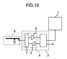
- Fig. 12 is a diagram showing a conventional radio equipment.
- the reference numeral 1 designates a host controller; 2, a radio module; 3, a base band controller; 4, an endless interface; 5, a power amplifier; 6, a low-noise input amplifier; 7, a switch; and 9, an antenna as an inverted F antenna.
- the host controller 1 transfers data to the base band controller 3.
- the base band controller 3 modulates the transferred data.
- the modulated electric signal is amplified by the output amplifier 5 and radiated as a radio wave from the antenna 9 to space through the switch 7.
- a radio wave propagated through the space is received in the antenna 9 and amplified by the low-noise input amplifier 6 through the switch 7.
- the amplified electric signal is demodulated to data by the base band controller 3 and transferred to the host controller 1.
- the radio coverage range and the input receiver coverage in the radio equipment are also fixed. Accordingly, when, for example, a user of one radio equipment in which both coverage range and input receiver coverage are 10 m wants to communicate with another radio equipment having equal performance, the user (or the radio equipment itself) can judge whether the other radio equipment is in an area with a 10 m radius centering about the user or not.
- the user of the radio equipment cannot judge whether any other radio equipment is near the user in the area with a 10 m radius. In other words, the user cannot specify who is the other radio equipment existing near the radio equipment of the user himself/herself. Furthermore, the user of the radio equipment cannot confirm whether the other radio equipment is coming near to or going far away from the user himself/herself.
- the output of the power amplifier 5 is variable.
- the ratio of output to input sensitivity varies, so that the radio coverage range depending on the output is not equal to the input receiver coverage of the radio wave depending on the input sensitivity.
- the forefront of the queue that is, the first radio equipment as a party to be serviced cannot be identified and priority cannot be distinguished between radio equipments registered as the queue.
- An object of the invention is to change both input receiver coverage and coverage range of a radio equipment dynamically without change of the ratio between the two ranges to thereby specify a communication party and to particularly specify whether the other radio equipment is coming near to or going far away from the radio equipment.
- a device for changing the intensity of input/output signals specifically, an attenuator is inserted between an antenna and a radio module, and there is provided means for relationally raising and lowering output and input sensitivity by controlling the attenuator.
- the distance relation between radio equipments, especially a sequence of radio equipments registered in a queue and the radio equipment in the forefront of the queue are specified on the basis of difference between some radio equipment with which the radio equipment can communicate in an area with a 1 m radius and some radio equipment with which the radio equipment can communicate in an area with a 2 m radius when the radius as a set value of the attenuator is changed to 2 m and 1 m.
- an antenna and an antenna with attenuator are changed over by a switch so that the radio coverage range and the input receiver coverage can be increased and decreased while the balance of the radio coverage range and the input receiver coverage is kept good.
- linkage of the radio equipment to any other radio equipment is established, for example, in an area with a 10 m radius and then the antennas are changed over so that communication is continued while the radio coverage range and the input receiver coverage in the radio equipment are enlarged and reduced alternately between the area with a 10 m radius and the area with a 1 m radius.
- the radio equipment judges whether the other radio equipment is coming near to or going far away from the area with a 1 m radius.
- the other radio equipment reaching the area with a 1 m radius is specified in such a manner that communication is continued while the radio coverage range and the input receiver coverage in the radio equipment are enlarged and reduced alternately between the area with a 10 m radius and the area with a 1 m radius.
- Fig. 1 is a diagram showing a radio equipment to which the invention is applied;
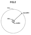
- Fig. 2 is a diagram showing a radio coverage range in the radio equipment to which the invention is applied;
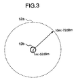
- Fig. 3 is a diagram showing an input receiver coverage of the radio wave in the radio equipment according to the invention;
- Fig. 4 is a diagram showing establishment of linkage of the radio equipment according to the invention;
- Fig. 5 is a diagram showing changing over the radio coverage range and the input receiver coverage in the radio equipment according to the invention;
- Fig. 6 is a diagram showing changing over the radio coverage range and the input receiver coverage and the outline of communication due to a timer;
- Fig. 7 is a diagram showing changing over the radio coverage range and the input receiver coverage and the outline of communication on the basis of detection means;
- Fig. 1 is a diagram showing a radio equipment to which the invention is applied;
- Fig. 2 is a diagram showing a radio coverage range in the radio equipment to which the invention is applied;
- Fig. 3 is
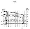
- Fig. 8 is a graph showing the relation between output and input sensitivity of the radio equipment according to the invention
- Fig. 9 is a diagram showing a first modified example of the radio equipment to which the invention is applied
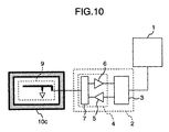
- Fig. 10 is a diagram showing a second modified example of the radio equipment to which the invention is applied
- Fig. 11 is a diagram showing a third modified example of the radio equipment to which the invention is applied
- Fig. 12 is a diagram showing a conventional technique
- Fig. 13 is a diagram showing a fourth modified example of the radio equipment to which the invention is applied
- Fig. 14 is a diagram showing a method for mounting the invention in a tray of a seat
- Fig. 15 is a diagram showing a fifth modified example of the radio equipment to which the invention is applied.
- Fig. 1 is a diagram showing an embodiment of a radio equipment to which the invention is applied.
- the reference numeral 1 designates a host controller; 2, a radio module; 3, a base band controller; 4, an endless interface; 5, a power amplifier; 6, a low-noise input amplifier; 7 and 8, switches; 91 and 92, inverted F antennas; and 10, an attenuator.
- the host controller 1 transfers data to the base band controller 3.
- the transferred data is modulated by the base band controller 3 and amplified by the output amplifier 5, so that the data reaches the switch 8 in the outside of the radio module 2 through the switch 7.
- the antenna 91 is connected to the switch 8 whereas the antenna 92 is connected to the switch 8 through the attenuator 10.
- the base band controller 3 controls the switch 8 to select either of the antennas 91 and 92.
- a radio wave is radiated to space from the antenna selected by the switch 8.
- the antennas 91 and 92 may be replaced by only one antenna 92 and configuration may be made so that the switch 8 can select whether the attenuator 10 is to be driven or not. In this configuration, the same effect as that of the invention can be generated in spite of reduction in the number of antennas.
- a radio wave propagated through space is received in each of the antennas 91 and 92.
- the received radio waves (data) are input from the antenna 91 to the switch 8 and from the antenna 92 to the switch 8 through the attenuator 10, respectively.
- the base band controller 3 controls the switch 8 to select either of the data input to the switch 8.
- the selected data is input to the radio module 2.
- the data input to the radio module 2 is amplified by the low-noise input amplifier 6 and demodulated by the base band controller 3.
- the demodulated data is transferred to the host controller 1.
- Fig. 2 is a diagram showing a radio coverage range in the radio equipment in Fig. 1.
- the reference numeral 11a designates a radio coverage range at an output of 0 dBm; and 11b, a radio coverage range at an output of -20 dBm.
- respective outputs of the antennas are set so that electric field intensity at a position in the coverage range 11a in the case of output through the antenna 91 becomes equal to that at a position in the coverage range 11b in the case of output through the antenna 92.
- Fig. 3 is a diagram showing an input receiver coverage of the radio wave in the radio equipment in Fig. 1.
- the reference numeral 12a designates an input receiver coverage at an input sensitivity of -72 dBm; and 12b, an input receiver coverage at an input sensitivity of -52 dBm.
- the switch 8 is changed over so that a radio wave output from a sender in the input receiver coverage 11a can be received when the data received in the antenna 91 is used whereas a radio wave output from the sender of the same output in the input receiver coverage 11b can be received when the data received in the antenna 92 is used.
- Fig. 4 is a diagram showing establishment of linkage of the radio equipment to which the invention is applied.
- the reference numeral 13 designates a radio equipment to which the invention is applied; 14a and 14b, conventional radio equipments; 15a, a radio coverage range and an input receiver coverage in the radio equipment 13; and 16, a radio coverage range and an input receiver coverage in the radio equipment 14a.
- the radio equipment 13 transmits and receives a radio wave at 10 dBm output and -72 dBm input sensitivity without interposition of the attenuator 10 by changing over the switch 8. On this occasion, the radio coverage range and the input receiver coverage in the radio equipment 13, that is, the radius of 15a is 10 m.
- the radio equipment 14a transmits and receives a radio wave at 10 dBm output and -72 dBm input sensitivity.
- the radio coverage range and the input receiver coverage in the radio equipment 14a, that is, the radius of 16 is 10 m which is equal to that in the radio equipment 13.
- the radio equipment 13 is within the radio coverage range 16 of the radio equipment 14a whereas the radio equipment 14a is within the radio coverage range 15a of the radio equipment 13. That is, electric field intensity at the position of each radio equipment is at the level allowing the output of the other radio equipment to be received. Accordingly, each radio equipment is at the distance allowing the other radio equipment to be called, so that linkage can be established.
- Fig. 5 is a diagram showing the case where the radio coverage range and the input receiver coverage of the radio equipment 13 in Fig. 4 is changed over.
- the reference numeral 15b designates a radio coverage range and an input receiver coverage in the radio equipment 13 in the case where a radio wave is transmitted and received in the antenna 92 through the attenuator 10.
- the radius of 15b is 1 m.
- Fig. 5 also shows a state in which the radio equipment 14a having established linkage to the radio equipment 13 in Fig. 4 is coming near to the radio equipment 13.
- the radio equipment 14a can only receive the radio wave output from the radio equipment 13 when the radio equipment 14a enters the circle of the radio coverage range and the input receiver coverage of the radio equipment 13 represented by 15b.
- the radio equipment 13 can only receive the radio wave output from the radio equipment 14a when the radio equipment 14a enters the circle of 15b. That is, when the radio coverage range and the input receiver coverage of the radio equipment 13 are reduced while the ratio between the two ranges is kept constant, the radio equipment 13 can communicate with only the radio equipment 14a which is coming near to the radio equipment 13.
- the radio equipment 13 detects the presence of the radio equipment 14a and the radio equipment 14b by using the radio coverage range and the input receiver coverage 15a.
- the radio equipment 13 changes over the antennas to select 15b as the radio coverage range and the input receiver coverage after the presence of these radio equipments is detected, the radio equipment with which the radio equipment 13 can communicate is only 14a which is coming near to the radio equipment 13.
- the radio equipment 13 can specify an array of radio equipments in the sequence of the radio equipment 14a and the radio equipment 14b viewed from the radio equipment 13 by confirming the difference between radio equipments with which the radio equipment 13 can communicate, that is, by confirming the presence/absence of radio equipments before and after change in the radio coverage range and the input receiver coverage.
- the radio equipment 14a is a radio equipment near the radio equipment 13.
- the radio equipment 13 can specify whether the radio equipment 14a having linkage established in the radio coverage range and the input receiver coverage 15b is coming near to or going far away from the radio equipment 13 after the linkage is established.
- the radio equipment 13 can specify the respective positions of the plurality of radio equipments.
- the radio equipments the positions of which can be specified may be conventional radio equipments each having a radio coverage range and an input receiver coverage of a predetermined value or about 10 m.
- Fig. 6 is a diagram showing communication timing in the case where the radio equipment (radio equipment 13) according to the invention changes over the radio coverage range and the input receiver coverage by a timer.
- the reference numerals 1301, 1302, 1303, 1304, 1305 and 1306 designate calls from the radio equipment 13; 14c and 14d, conventional radio equipments; and 1401, 1402, 1403, 1404 and 1405, replies from the radio equipments 14c and 14d.
- the vertical axis of the graph shows relative distances from the radio equipment 13 to the radio equipments 14c and 14d.
- the radio equipment 13 outputs a call 1301 with power of 0 dBm at time T0.
- the radio equipment 14c gives a reply 1401 at time T1.
- the radio equipment 13 outputs a call 1302 at time T2.
- the radio equipment 14c gives a reply 1402 at time T3.
- the radio equipment 13 Upon reception of the reply 1402, the radio equipment 13 changes over the output of the equipment to -20 dBm at the right time on the basis of the passage of a predetermined time according to the built-in timer. In Fig. 6, the radio equipment 13 changes over the output so that changing-over of the output will be completed at time T5. The radio equipment 13 outputs a call 1303 at time T6. In the diagram, there is however no reply from the radio equipment 14c to the radio equipment 13 because the radio equipment 14c is out of the radio coverage range of the radio equipment 13. When there is no reply, the radio equipment 13 makes a decision at time T7 that the radio equipment 14c is not approaching or is absent in the area with a 1 m radius centering about the radio equipment 13.
- the radio equipment 13 outputs a call 1304 again at time T8.
- the radio equipment 14c in the area with a 1 m radius centering about the radio equipment 13 can receive the call 1304.
- the radio equipment 14c Upon reception of the call 1403, the radio equipment 14c gives a reply 1403 at time T9.
- the radio equipment 13 Upon reception of the reply 1403, the radio equipment 13 recognizes the presence of the radio equipment 14c in the area with a 1 m radius centering about the radio equipment 13 and prepares for service provision. The radio equipment 13 returns the output to 0 dBm while preparing for service.
- the radio equipment 13 outputs a call 1305 with power of 0 dBm at time T12.
- the radio equipment 14d gives a reply 1404 at time T13.
- the radio equipment 13 changes over its own output to -20 dBm at time T14 and outputs a call 1306.
- the call 1306 is received in the radio equipment 14c waiting for the start of service provision in a neighbor of the radio equipment 13.
- the radio equipment 14c gives a reply 1405 at time T15. By such exchange, service is provided to 14c.
- the radio equipment 13 having succeeded in calling the radio equipment 14d at the output of 0 dBm changes over its own output to -20 dBm after the passage of a predetermined time according to the timer in the same manner as described above and detects approach of the called radio equipment 14d.
- the radio equipment 13 having succeeded in detecting the approach begins to prepare for provision of service in the same manner as in the case of the radio equipment 14c.
- the radio equipment 13 changes over its output to 0 dBm and calls another radio equipment until preparation for provision of service is completed.
- preparation for provision of service is completed, the radio equipment 13 changes over its output to -20 dBm again.
- the radio equipment 13 then calls the radio equipment 14d kept waiting near the radio equipment 13 and begins to provide service. In this manner, the timer is used for efficiently detecting approach of the radio equipment and proving service.
- Fig. 7 is a diagram showing timing of changing over the radio coverage range and the input receiver coverage and timing of communication in the case where the radio equipment 13 has a radiation sensor as detection means for detecting other radio equipments.
- the reference numerals 1307, 1308, 1309, 1310, 1311 and 1312 designate calls; 14e and 14f, radio equipments; and 1406, 1407, 1408, 1409 and 1410, replies.
- the vertical axis shows relative distances of the radio equipment 13 to the radio equipments 14e and 14f.
- the radio equipment 13 outputs a call 1307 at time T0 and outputs a call 1308 with power of 0 dBm at time T2.
- the radio equipment 14e Upon reception of the call 1307, the radio equipment 14e gives a reply 1406 at time T1.
- the radio equipment 14f gives a reply 1407 at time T3.
- the radio equipment 13 After confirming the radio equipment replying in the input receiver coverage with a 10 m radius, the radio equipment 13 changes over its output to -20 dBm. In the diagram, changing-over of the output is completed at time T4.
- the radio equipment 13 detects approach of the other radio equipment by a radiation sensor included in the host controller 1. Upon detection of approach of the radio equipment 14e by the radiation sensor, the radio equipment 13 outputs a call 1309 at time T6.
- the radio equipment 14e gives no reply to the radio equipment 13 because the assumption that the call 1309 is not for the radio equipment 14e is made. When there is no reply, the radio equipment 13 recognizes that the called radio equipment is not coming near to the radio equipment 13. Continuously, the radio equipment 13 outputs a call 1310 addressed to the radio equipment 14e at time T8.
- the radio equipment 14e Upon reception of the call 1310, the radio equipment 14e gives a reply 1408 at time T9.
- the radio equipment 13 Upon reception of the reply 1408, the radio equipment 13 recognizes the presence of the radio equipment 14e in the neighbor of the area with a 1 m radius centering about the radio equipment 13, so that the radio equipment 13 can confirm the radio equipment reaching a neighbor of the radio equipment 13.
- the radio equipment 13 outputs a call 1311 at time T10 and begins to provide service to the radio equipment 14e, such as sending of an electronic ticket, sending of electronic money, provision of information, and so on.
- the radio equipment 14e gives a reply 1409 at time T11, the provision of this service is completed.
- the radio equipment 13 Until the provision of service to the radio equipment 14e is completed, the radio equipment 13 does not detect approach of other radio equipments than the radio equipment 14e. Therefore, upon completion of the provision of service to the radio equipment 14e, the radio equipment 13 returns its output to 0 dBm in order to provide service to another radio equipment. In the diagram, changing-over of the output is completed at time T12.
- the radio equipment 13 outputs a call 1312 at time T14 to tell the other radio equipment that provision of service to the other radio equipment is enabled.
- the radio equipment 14f gives a reply 1410 at time T15.
- the call 1312 is a call for urging the radio equipment 14f to come near to the radio equipment 13.
- the radio equipment 13 having succeeded in calling the radio equipment 14f at an output of 0 dBm begins to prepare for provision of service. During this time, the radio equipment 13 continuously calls another radio equipment newly entering the input receiver coverage of the radio equipment 13. When the radiation sensor detects approach of another radio equipment to the neighbor of the radio equipment 13, the radio equipment 13 changes over its output to -20 dBm and specifies the called radio equipment. The radio equipment 13 having succeeded in specifying the radio equipment provides the prepared service. Upon detection of approach of another radio equipment at the time of provision of service, the radio equipment 13 specifies the radio equipment continuously at an output of -20 dBm after the provision of service and provides service.
- the radio equipment 13 When approach of another radio equipment is not detected at the time of provision of service, the radio equipment 13 changes over its output mode to 0 dBm again, calls another radio equipment and urges the radio equipment to come near to the radio equipment 13 if necessary. Accordingly, the radio equipment 13 can control approach of a plurality of radio equipments and can provide service to the plurality of radio equipments sequentially.
- Fig. 8 is a graph showing the relation between output and input sensitivity in the radio equipment 13.
- the reference numeral 130 designates input sensitivity of the radio equipment 13; and 140 and 141, input sensitivities of a conventional radio equipment.
- the input sensitivity of the radio equipment is set in consideration of the noise level in the periphery of the radio equipment. Specifically, a noise margin of 50 dB is taken for a required sensitivity. That is, the input sensitivity of the radio equipment is defined in such a manner that a noise margin of 50 dB is added to electric field intensity in the periphery.
- the input sensitivity of the conventional radio equipment is -72 dBm.
- the output of the radio equipment 14a located at a distance of 0 m is received at the input sensitivity 140 tinged with the noise margin of 50 dB by the conventional radio equipment located at a distance of 10 m. That is, the outputs of conventional radio equipments can be received by each other if the conventional radio equipments are at a distance of 10 m from each other.
- the output of the radio equipment 13 when the output of the radio equipment 13 is to be received by the conventional radio equipment, the output of the radio equipment 13 located at a distance of 0 m in the graph has been already attenuated by 20 dBm by the attenuator. Accordingly, the distance in which the conventional radio equipment with input sensitivity of -72 dBm can keep the noise margin of 50 dB, that is, the distance in which the conventional radio equipment can receive the output of the radio equipment 13 is 1 m as represented by the position of input sensitivity 141 of the conventional radio equipment.
- the radio equipment to which the invention is applied is not only compatible with the conventional radio equipment in terms of connection to the conventional radio equipment at the output through the antenna 91 but also kept compatible with the conventional radio equipment in terms of connection to the conventional radio equipment even at a near distance of 1 m if the antenna 91 is changed over to the antenna 92 with the attenuator 10.
- the radio coverage range and the input receiver coverage can be dynamically changed over, for example, to 10 m and 1 m.
- Fig. 9 is a diagram showing a first modified example of the radio equipment to which the invention is applied.
- the reference numeral 10b designates an attenuator; 101, a splitter; and 102, a balun or terminator.
- Data output from the radio module 2 is input to the attenuator 10b.
- the attenuator 10b Whenever the data input to the attenuator 10b is split into two by the splitter 101 included in the attenuator 10b, the intensity of the data is attenuated to a half.
- the split data is output from one branch of the splitter 101 to the antenna 9.
- the data reaching the other branches are terminated by the terminators 102 attached to ends of the branches respectively.
- both output and input can be attenuated at the same ratio by the splitter 101. Accordingly, the radio coverage range and the input receiver coverage can be reduced while balance of the two ranges is kept constant.
- Fig. 10 is a diagram showing a second modified example of the radio equipment to which the invention is applied.
- the reference numeral 10c designates an attenuating device including metal pieces.
- the antenna 9 is wrapped in the attenuating device 10c so that the radio coverage range and the input receiver coverage of the radio equipment can be reduced while balance of the two ranges is kept constant.
- Fig. 11 is a diagram showing a third modified example of the radio equipment to which the invention is applied.
- the reference numeral 5a designates a variable output power amplifier; and 17, a mixer circuit.
- the mixer circuit 17 has a noise source 170.
- the final stage of the variable output power amplifier 5a has a plurality of power amplifiers. Accordingly, the output of the variable output power amplifier 5a varies in accordance with the number of power amplifiers switched on.
- the plurality of power amplifiers may be all equal in transistor size and area or may be different from one another in transistor size and area. Incidentally, the output of the variable output power amplifier 5a increases in proportion to the area of transistors of power amplifiers switched on. Accordingly, it is necessary to incorporate the plurality of power amplifiers in the variable output power amplifier 5a so that a required output can be obtained in the variable output power amplifier 5a.
- the base band controller 3 controls the number of power amplifiers switched on in the variable output power amplifier 5a.
- variable output power amplifier 5a When, for example, all the plurality of power amplifiers are switched on, a coverage range with a 10 m radius is achieved by the variable output power amplifier 5a. When, for example, only one power amplifier is switched on, a coverage range with a 1 m radius is achieved by the variable output power amplifier 5a.
- Data received in the antenna 9 is input to the mixer circuit 17.
- the mixer circuit 17 mixes the input data with noise generated in the noise source 170 and outputs the mixture to the low-noise input amplifier 6. Because noise is mixed, the input sensitivity of the low-noise input amplifier 6 is reduced from -70 dBm to -50 dBm.
- the base band controller 3 suppresses the output of noise by directly controlling the noise source 170.
- the radio coverage range and the input receiver coverage can be reduced while balance of the two ranges is kept constant by the radio interface 4 having the variable output power amplifier 5a and the mixer circuit 17.
- the base band controller 3 can control the radio coverage range by controlling the variable output power amplifier 5a.
- the base band controller 3 can adjust the input receiver coverage finely by controlling the noise source 170.
- Fig. 13 is a diagram showing a fourth modified example of the radio equipment to which the invention is applied.
- the reference numeral 18 designates a printed circuit board; 181, a plate metal conductor which is a ground layer in inner layers of the printed circuit board 18; 182, a plate metal conductor which is an electric power supply layer in inner layers of the printed circuit board 18; and 93 and 94, antennas.
- the radio module 2, the switch 8 and the antennas 93 and 94 are mounted on a surface of the printed circuit board 18.
- the plate metal conductor 181 as a ground layer and the plate metal conductor 182 as an electric power supply layer are disposed as inner layers of the printed circuit board 18 successively viewed from the side near the radio module 2.
- the plate metal conductors 181 and 182 supply electric power to the radio module 2 and the switch 8.
- the antenna 93 is disposed so as to overlap the plate metal conductors 181 and 182 viewed from above the printed circuit board 18. When viewed from above the printed circuit board 18, the antenna 93 has no portion not overlapping the plate metal conductors 181 and 182.
- the gap between the antenna 93 and nearer one of the plate metal conductors 181 and 182 to the antenna 93 is in a range of from 0.1 mm to 2 mm. This gap comes from the thickness of an electrically insulating film inserted between the metal conductors. Sufficient insulation withstand voltage and parasitic capacitance can be achieved by this thickness.
- the printed circuit board 18 is produced in such a manner that electrically insulating films and metal conductors are piled up alternately like a sandwich. The thickness of the printed circuit board 18 is limited to about 2 mm by a board-producing apparatus. If the gap is secured, sufficient insulation withstand voltage and parasitic capacitance, however, can be achieved even in the case where the printed circuit board 18 is about 2 mm thick.
- the same performance as described above can be achieved if the aforementioned gap is selected to be in a range of from 0.1 mm to 2 mm.
- the antenna 94 is disposed so as not to overlap the plate metal conductors 181 and 182 viewed from above the printed circuit board 18.
- the antenna 94 has no portion overlapping the plate metal conductors 181 and 182.
- Data output from the radio module 2 is input to the antenna 93 or 94 through the switch 8.
- the switch 8 changes over a circuit so as to be electrically connected to either the antenna 93 or the antenna 94.
- Capacitance is parasitic between the antenna 93 and the plate metal conductors 181 and 182, so that the resonance frequency of the antenna 93 is reduced. Accordingly, SWR becomes high, so that the rate of radiation of electric power from the antenna 93 to space is reduced.
- electric power radiated from the antenna 93 to space is lower than electric power radiated from the antenna 92 to space because of generation of parasitic capacitance and absorption of magnetic flux.
- the antenna gain at the time of input to the antenna 93 is lower than that at the time of input to the antenna 94.
- the radio coverage range and the input receiver coverage can be dynamically changed over, for example, to 10 m and 1 m.
- Fig. 14 is a diagram showing a state in which the radio equipment to which the invention is applied is mounted in a back rest of a seat in an electric car, an airplane, or the like.
- the reference numeral 20 designates a rear surface of the back rest; 201, a tray mounted in the rear surface of the back rest; 202, a latch for fixing the tray; 203, a beam and hinge of the tray; 94t, a tray built-in antenna on the tray upper surface side; and 94b, a tray built-in antenna on the tray floor surface side.
- This diagram shows a state in which the tray 201 is fixed to the rear surface 20 of the back rest of a front seat by the latch 202.
- the tray 201 includes the radio module 2, the switch 8, the antenna 93, the tray upper surface side tray built-in antenna 94t, and the tray floor surface side tray built-in antenna 94b.
- the tray upper surface side tray built-in antenna 94t and the tray floor surface side tray built-in antenna 94b are attenuating function-including antennas.
- the tray upper surface side tray built-in antenna 94t has a radiation pattern covering a neighbor of the upper surface of the tray.
- the tray floor surface side tray built-in antenna 94b has a radiation pattern covering a neighbor of the floor surface side of the tray.
- the antenna 93 has a radiation pattern widely covering both the upper surface side and the floor surface side of the tray.
- the radio module 2 uses the antenna 93 when it starts. Then, the radio module 2 changes over the used antenna to the tray floor surface side tray built-in antenna 94b or the tray upper surface side tray built-in antenna 94t by using the switch 8 when the radio module 2 begins to provide service to the user.
- the radio equipment built in the tray can communicate with a neighbor of the tray, specifically only a neighbor of a seated person using the tray. As a result, only the radio equipment used by the user in the seat can communicate with the radio equipment built in the tray.
- the radio module 2 detects the position of the tray 201 by detecting the fact that the latch 202 is located in a latch position or the fact that the beam and hinge 203 of the tray 201 is not located in a bending position.
- the radio module 2 selects and uses the tray floor surface side tray built-in antenna 94b at the time of storage of the tray 210 and the tray upper surface side tray built-in antenna 94t at the time of extraction of the tray 201 on the basis of the detected information.
- Fig. 15 is a diagram showing a fifth modified example of the radio equipment to which the invention is applied.
- the reference numeral 183 designates a plate metal conductor in inner layers of the printed circuit board 18; 19, a switch; and 95, an antenna.
- the switch 19 may be replaced by a relay circuit.
- the radio module 2 and the antenna 95 are mounted on a front surface of the printed circuit board 18.
- the switch 19 is mounted on a rear surface of the printed circuit board 18.
- the plate metal conductor 181 and the plate metal conductor 182 are disposed as inner layers of the printed circuit board successively viewed from the side near the radio module 2.
- the plate metal conductors 181 and 182 supply electric power to the radio module 2 and the switch 19.
- the antenna 95 is disposed so as to overlap the plate metal conductor 183 viewed from above the printed circuit board 18.
- the antenna 94 has no portion not overlapping the plate metal conductor 183.
- the gap between the antenna 93 and the plate metal conductor 183 is in a range of from 0.1 mm to 2 mm.
- the switch 19 controls electrical connection between the plate metal conductor 181 as a ground layer and the plate metal conductor 183 by turning on and off.
- the switch 19 electrically connects the plate metal conductor 181 as a ground layer to the plate metal conductor 183, electric power radiated from the antenna 95 to space is reduced and the antenna gain at the time of input is reduced because of parasitic capacitance and absorption of magnetic flux.
- the radio coverage range and the input receiver coverage of the radio equipment can be dynamically changed over, for example, to 10 m and 1 m.
- the radio equipment to which the invention is applied can roughly classify other radio equipments in a radio network into radio equipments out of the input receiver coverage and radio equipments within the input receiver coverage by controlling and reducing the input receiver coverage of the equipment itself.
- the radio equipment to which the invention is applied behaves as a hidden terminal to the radio equipments out of the input receiver coverage. Because the radio equipment behaves as a hidden terminal, the radio equipment does not reply to the radio equipments out of the input receiver coverage at all and there is no call reaching the radio equipments out of the input receiver coverage. In this manner, the radio equipment to which the invention is applied can divide the radio network dynamically for convenience' sake.
- the radio equipment to which the invention is applied can be used for constructing a radio network so that linkages between the radio equipment and a plurality of radio equipments can be ceased at once intentionally.
- the invention is useful in dynamically changing the radio coverage range and the input receiver coverage in the radio equipment.
- the invention is also useful in confirming relative distances between radio equipments.
- the invention is further useful in exchanging service efficiently in a radio network.
Landscapes
- Engineering & Computer Science (AREA)
- Computer Networks & Wireless Communication (AREA)
- Signal Processing (AREA)
- Mobile Radio Communication Systems (AREA)
- Transceivers (AREA)
Abstract
A radio equipment, wherein an attenuator (10)
is inserted between antennas (91, 92) and a radio
module (2), and output and input sensitivities are
raised and lowered simultaneously so as to keep the
balance of a radio covering range with an input
receiver coverage at a constant, and the antenna (91)
and the antenna (92) with attenuator are switched over
by a switch (8) to increase and decrease the radio
coverage range and input receiver coverage while
keeping the balance of the dynamic radio coverage range
with the input receiver coverage.
Description
The present invention relates to a radio
equipment for performing radio communication,
especially control and shaping of a communication
range.
Fig. 12 is a diagram showing a conventional
radio equipment. In the diagram, the reference numeral
1 designates a host controller; 2, a radio module; 3, a
base band controller; 4, an endless interface; 5, a
power amplifier; 6, a low-noise input amplifier; 7, a
switch; and 9, an antenna as an inverted F antenna.
In the diagram, the host controller 1
transfers data to the base band controller 3. The base
band controller 3 modulates the transferred data. The
modulated electric signal is amplified by the output
amplifier 5 and radiated as a radio wave from the
antenna 9 to space through the switch 7. On the other
hand, a radio wave propagated through the space is
received in the antenna 9 and amplified by the low-noise
input amplifier 6 through the switch 7. Then,
the amplified electric signal is demodulated to data by
the base band controller 3 and transferred to the host
controller 1.
In the conventional radio equipment, because
the output of the power amplifier 5 and the input
sensitivity of the low-noise input amplifier 6 are
fixed, the radio coverage range and the input receiver
coverage in the radio equipment are also fixed.
Accordingly, when, for example, a user of one radio
equipment in which both coverage range and input
receiver coverage are 10 m wants to communicate with
another radio equipment having equal performance, the
user (or the radio equipment itself) can judge whether
the other radio equipment is in an area with a 10 m
radius centering about the user or not.
The user of the radio equipment cannot judge
whether any other radio equipment is near the user in
the area with a 10 m radius. In other words, the user
cannot specify who is the other radio equipment
existing near the radio equipment of the user
himself/herself. Furthermore, the user of the radio
equipment cannot confirm whether the other radio
equipment is coming near to or going far away from the
user himself/herself.
On the other hand, there is a radio equipment
in which the output of the power amplifier 5 is
variable. In the radio equipment, however, the ratio
of output to input sensitivity varies, so that the
radio coverage range depending on the output is not
equal to the input receiver coverage of the radio wave
depending on the input sensitivity.
When, for example, the output of a radio
equipment used as a base station at a certain point of
time is raised, electric field intensity around the
base station becomes so high that the coverage range is
widened. Accordingly, a radio wave from the base
station is audible to any radio equipment existing
within the widened coverage range. When the base
station calls any ambient radio equipment in this
state, the ambient radio equipment tries to reply to
the base station but linkage to the base station cannot
be established because the output of the ambient radio
equipment is low yet. Furthermore, there is a
disadvantage that normal communication is disabled
because the ambient radio equipment does nothing but
repeat replying.
When the output of a radio equipment used as
a mobile station at a certain point of time is lowered,
electric field intensity around the mobile station is
reduced so that the radio coverage range is narrowed.
Accordingly, a radio wave cannot reach any radio
equipments around the mobile station except radio
equipments close to the mobile station. When a radio
equipment not close to the mobile station calls in this
state, the mobile station tries to reply to the calling
radio equipment because the input receiver coverage of
the mobile station is kept as it is. The output of the
mobile station is however low, so that the radio wave
cannot reach the calling radio equipment.
Communication with calling the radio equipment is
ceased and new linkage cannot be established.
Furthermore, there is a disadvantage that normal
communication is disabled because the mobile station
does nothing but repeat replying.
In addition, in an environment in which a
plurality of mobile stations generate a queue for a
radio equipment which is a base station, for example,
in a vending machine (base station) providing service
on the basis of requests from radio equipments (mobile
stations), the forefront of the queue, that is, the
first radio equipment as a party to be serviced cannot
be identified and priority cannot be distinguished
between radio equipments registered as the queue.
An object of the invention is to change both
input receiver coverage and coverage range of a radio
equipment dynamically without change of the ratio
between the two ranges to thereby specify a
communication party and to particularly specify whether
the other radio equipment is coming near to or going
far away from the radio equipment.
To achieve the foregoing object, in
accordance with the invention, in a radio equipment, a
device for changing the intensity of input/output
signals, specifically, an attenuator is inserted
between an antenna and a radio module, and there is
provided means for relationally raising and lowering
output and input sensitivity by controlling the
attenuator.
According to a preferred embodiment of the
invention, the distance relation between radio
equipments, especially a sequence of radio equipments
registered in a queue and the radio equipment in the
forefront of the queue are specified on the basis of
difference between some radio equipment with which the
radio equipment can communicate in an area with a 1 m
radius and some radio equipment with which the radio
equipment can communicate in an area with a 2 m radius
when the radius as a set value of the attenuator is
changed to 2 m and 1 m.
In another embodiment of the invention, in
the radio equipment, an antenna and an antenna with
attenuator are changed over by a switch so that the
radio coverage range and the input receiver coverage
can be increased and decreased while the balance of the
radio coverage range and the input receiver coverage is
kept good.
In a further embodiment of the invention,
linkage of the radio equipment to any other radio
equipment is established, for example, in an area with
a 10 m radius and then the antennas are changed over so
that communication is continued while the radio
coverage range and the input receiver coverage in the
radio equipment are enlarged and reduced alternately
between the area with a 10 m radius and the area with a
1 m radius. As a result, the radio equipment judges
whether the other radio equipment is coming near to or
going far away from the area with a 1 m radius.
In a further embodiment of the invention,
after linkage to some radio equipment which belongs to
a plurality of other radio equipments and which is, for
example, in an area with a 10 m radius is established,
the other radio equipment reaching the area with a 1 m
radius is specified in such a manner that communication
is continued while the radio coverage range and the
input receiver coverage in the radio equipment are
enlarged and reduced alternately between the area with
a 10 m radius and the area with a 1 m radius.
Fig. 1 is a diagram showing a radio equipment
to which the invention is applied; Fig. 2 is a diagram
showing a radio coverage range in the radio equipment
to which the invention is applied; Fig. 3 is a diagram
showing an input receiver coverage of the radio wave in
the radio equipment according to the invention; Fig. 4
is a diagram showing establishment of linkage of the
radio equipment according to the invention; Fig. 5 is a
diagram showing changing over the radio coverage range
and the input receiver coverage in the radio equipment
according to the invention; Fig. 6 is a diagram showing
changing over the radio coverage range and the input
receiver coverage and the outline of communication due
to a timer; Fig. 7 is a diagram showing changing over
the radio coverage range and the input receiver
coverage and the outline of communication on the basis
of detection means; Fig. 8 is a graph showing the
relation between output and input sensitivity of the
radio equipment according to the invention; Fig. 9 is a
diagram showing a first modified example of the radio
equipment to which the invention is applied; Fig. 10 is
a diagram showing a second modified example of the
radio equipment to which the invention is applied; Fig.
11 is a diagram showing a third modified example of the
radio equipment to which the invention is applied; Fig.
12 is a diagram showing a conventional technique; Fig.
13 is a diagram showing a fourth modified example of
the radio equipment to which the invention is applied;
Fig. 14 is a diagram showing a method for mounting the
invention in a tray of a seat; and Fig. 15 is a diagram
showing a fifth modified example of the radio equipment
to which the invention is applied.
Fig. 1 is a diagram showing an embodiment of
a radio equipment to which the invention is applied.
In Fig. 1, the reference numeral 1 designates
a host controller; 2, a radio module; 3, a base band
controller; 4, an endless interface; 5, a power
amplifier; 6, a low-noise input amplifier; 7 and 8,
switches; 91 and 92, inverted F antennas; and 10, an
attenuator.
The host controller 1 transfers data to the
base band controller 3. The transferred data is
modulated by the base band controller 3 and amplified
by the output amplifier 5, so that the data reaches the
switch 8 in the outside of the radio module 2 through
the switch 7. The antenna 91 is connected to the
switch 8 whereas the antenna 92 is connected to the
switch 8 through the attenuator 10. When the data
reaching the switch 8 is to be output through antenna,
the base band controller 3 controls the switch 8 to
select either of the antennas 91 and 92. A radio wave
is radiated to space from the antenna selected by the
switch 8.
Incidentally, the antennas 91 and 92 may be
replaced by only one antenna 92 and configuration may
be made so that the switch 8 can select whether the
attenuator 10 is to be driven or not. In this
configuration, the same effect as that of the invention
can be generated in spite of reduction in the number of
antennas.
On the other hand, a radio wave propagated
through space is received in each of the antennas 91
and 92. The received radio waves (data) are input from
the antenna 91 to the switch 8 and from the antenna 92
to the switch 8 through the attenuator 10,
respectively. The base band controller 3 controls the
switch 8 to select either of the data input to the
switch 8. The selected data is input to the radio
module 2. The data input to the radio module 2 is
amplified by the low-noise input amplifier 6 and
demodulated by the base band controller 3. The
demodulated data is transferred to the host controller
1.
Fig. 2 is a diagram showing a radio coverage
range in the radio equipment in Fig. 1. The reference
numeral 11a designates a radio coverage range at an
output of 0 dBm; and 11b, a radio coverage range at an
output of -20 dBm. In this embodiment, respective
outputs of the antennas are set so that electric field
intensity at a position in the coverage range 11a in
the case of output through the antenna 91 becomes equal
to that at a position in the coverage range 11b in the
case of output through the antenna 92.
Fig. 3 is a diagram showing an input receiver
coverage of the radio wave in the radio equipment in
Fig. 1. The reference numeral 12a designates an input
receiver coverage at an input sensitivity of -72 dBm;
and 12b, an input receiver coverage at an input
sensitivity of -52 dBm. In this embodiment, the switch
8 is changed over so that a radio wave output from a
sender in the input receiver coverage 11a can be
received when the data received in the antenna 91 is
used whereas a radio wave output from the sender of the
same output in the input receiver coverage 11b can be
received when the data received in the antenna 92 is
used.
Fig. 4 is a diagram showing establishment of
linkage of the radio equipment to which the invention
is applied. In the diagram, the reference numeral 13
designates a radio equipment to which the invention is
applied; 14a and 14b, conventional radio equipments;
15a, a radio coverage range and an input receiver
coverage in the radio equipment 13; and 16, a radio
coverage range and an input receiver coverage in the
radio equipment 14a.
The radio equipment 13 transmits and receives
a radio wave at 10 dBm output and -72 dBm input
sensitivity without interposition of the attenuator 10
by changing over the switch 8. On this occasion, the
radio coverage range and the input receiver coverage in
the radio equipment 13, that is, the radius of 15a is
10 m.
The radio equipment 14a transmits and
receives a radio wave at 10 dBm output and -72 dBm
input sensitivity. The radio coverage range and the
input receiver coverage in the radio equipment 14a,
that is, the radius of 16 is 10 m which is equal to
that in the radio equipment 13.
In Fig. 4, the radio equipment 13 is within
the radio coverage range 16 of the radio equipment 14a
whereas the radio equipment 14a is within the radio
coverage range 15a of the radio equipment 13. That is,
electric field intensity at the position of each radio
equipment is at the level allowing the output of the
other radio equipment to be received. Accordingly,
each radio equipment is at the distance allowing the
other radio equipment to be called, so that linkage can
be established.
Fig. 5 is a diagram showing the case where
the radio coverage range and the input receiver
coverage of the radio equipment 13 in Fig. 4 is changed
over. In the diagram, the reference numeral 15b
designates a radio coverage range and an input receiver
coverage in the radio equipment 13 in the case where a
radio wave is transmitted and received in the antenna
92 through the attenuator 10. In this case, the radius
of 15b is 1 m.
Fig. 5 also shows a state in which the radio
equipment 14a having established linkage to the radio
equipment 13 in Fig. 4 is coming near to the radio
equipment 13. In this case, the radio equipment 14a
can only receive the radio wave output from the radio
equipment 13 when the radio equipment 14a enters the
circle of the radio coverage range and the input
receiver coverage of the radio equipment 13 represented
by 15b.
Although the output of the radio equipment
14a is always high, the output sensitivity of the radio
equipment 13 is lowered by -20 dBm by the attenuator
10. That is, the input receiver coverage is narrowed
to 15b. Accordingly, the radio equipment 13 can only
receive the radio wave output from the radio equipment
14a when the radio equipment 14a enters the circle of
15b. That is, when the radio coverage range and the
input receiver coverage of the radio equipment 13 are
reduced while the ratio between the two ranges is kept
constant, the radio equipment 13 can communicate with
only the radio equipment 14a which is coming near to
the radio equipment 13.
Assume further that the radio equipment 14b
is in the rear of the radio equipment 14a sequentially.
In this case, the radio equipment 13 detects the
presence of the radio equipment 14a and the radio
equipment 14b by using the radio coverage range and the
input receiver coverage 15a. When the radio equipment
13 changes over the antennas to select 15b as the radio
coverage range and the input receiver coverage after
the presence of these radio equipments is detected, the
radio equipment with which the radio equipment 13 can
communicate is only 14a which is coming near to the
radio equipment 13. In this case, the radio equipment
13 can specify an array of radio equipments in the
sequence of the radio equipment 14a and the radio
equipment 14b viewed from the radio equipment 13 by
confirming the difference between radio equipments with
which the radio equipment 13 can communicate, that is,
by confirming the presence/absence of radio equipments
before and after change in the radio coverage range and
the input receiver coverage. In addition, it can be
specified that the radio equipment 14a is a radio
equipment near the radio equipment 13.
As described above in Figs. 4 and 5, because
the radio equipment 13 has means for changing over the
radio coverage range and the input receiver coverage,
the radio equipment 13 can specify whether the radio
equipment 14a having linkage established in the radio
coverage range and the input receiver coverage 15b is
coming near to or going far away from the radio
equipment 13 after the linkage is established.
When there are a plurality of radio
equipments, the radio equipment 13 can specify the
respective positions of the plurality of radio
equipments. In this case, the radio equipments the
positions of which can be specified may be conventional
radio equipments each having a radio coverage range and
an input receiver coverage of a predetermined value or
about 10 m.
Fig. 6 is a diagram showing communication
timing in the case where the radio equipment (radio
equipment 13) according to the invention changes over
the radio coverage range and the input receiver
coverage by a timer. In the diagram, the reference
numerals 1301, 1302, 1303, 1304, 1305 and 1306
designate calls from the radio equipment 13; 14c and
14d, conventional radio equipments; and 1401, 1402,
1403, 1404 and 1405, replies from the radio equipments
14c and 14d. In Fig. 6, the vertical axis of the graph
shows relative distances from the radio equipment 13 to
the radio equipments 14c and 14d.
The radio equipment 13 outputs a call 1301
with power of 0 dBm at time T0. Upon reception of the
call 1301, the radio equipment 14c gives a reply 1401
at time T1. Continuously, the radio equipment 13
outputs a call 1302 at time T2. Upon reception of the
call 1302, the radio equipment 14c gives a reply 1402
at time T3.
Upon reception of the reply 1402, the radio
equipment 13 changes over the output of the equipment
to -20 dBm at the right time on the basis of the
passage of a predetermined time according to the built-in
timer. In Fig. 6, the radio equipment 13 changes
over the output so that changing-over of the output
will be completed at time T5. The radio equipment 13
outputs a call 1303 at time T6. In the diagram, there
is however no reply from the radio equipment 14c to the
radio equipment 13 because the radio equipment 14c is
out of the radio coverage range of the radio equipment
13. When there is no reply, the radio equipment 13
makes a decision at time T7 that the radio equipment
14c is not approaching or is absent in the area with a
1 m radius centering about the radio equipment 13.
Continuously, the radio equipment 13 outputs
a call 1304 again at time T8. At the time T8, the
radio equipment 14c in the area with a 1 m radius
centering about the radio equipment 13 can receive the
call 1304. Upon reception of the call 1403, the radio
equipment 14c gives a reply 1403 at time T9.
Upon reception of the reply 1403, the radio
equipment 13 recognizes the presence of the radio
equipment 14c in the area with a 1 m radius centering
about the radio equipment 13 and prepares for service
provision. The radio equipment 13 returns the output
to 0 dBm while preparing for service.
The radio equipment 13 outputs a call 1305
with power of 0 dBm at time T12. Upon reception of the
call 1305, the radio equipment 14d gives a reply 1404
at time T13. When the preparation for service is
completed in the meantime, the radio equipment 13
changes over its own output to -20 dBm at time T14 and
outputs a call 1306. The call 1306 is received in the
radio equipment 14c waiting for the start of service
provision in a neighbor of the radio equipment 13.
Upon reception of the call 1306, the radio equipment
14c gives a reply 1405 at time T15. By such exchange,
service is provided to 14c.
The radio equipment 13 having succeeded in
calling the radio equipment 14d at the output of 0 dBm
changes over its own output to -20 dBm after the
passage of a predetermined time according to the timer
in the same manner as described above and detects
approach of the called radio equipment 14d. The radio
equipment 13 having succeeded in detecting the approach
begins to prepare for provision of service in the same
manner as in the case of the radio equipment 14c. At
the same time, the radio equipment 13 changes over its
output to 0 dBm and calls another radio equipment until
preparation for provision of service is completed.
When preparation for provision of service is completed,
the radio equipment 13 changes over its output to -20
dBm again. The radio equipment 13 then calls the radio
equipment 14d kept waiting near the radio equipment 13
and begins to provide service. In this manner, the
timer is used for efficiently detecting approach of the
radio equipment and proving service.
Fig. 7 is a diagram showing timing of
changing over the radio coverage range and the input
receiver coverage and timing of communication in the
case where the radio equipment 13 has a radiation
sensor as detection means for detecting other radio
equipments. In the diagram, the reference numerals
1307, 1308, 1309, 1310, 1311 and 1312 designate calls;
14e and 14f, radio equipments; and 1406, 1407, 1408,
1409 and 1410, replies. The vertical axis shows
relative distances of the radio equipment 13 to the
radio equipments 14e and 14f.
The radio equipment 13 outputs a call 1307 at
time T0 and outputs a call 1308 with power of 0 dBm at
time T2. Upon reception of the call 1307, the radio
equipment 14e gives a reply 1406 at time T1. Upon
reception of the call 1308, the radio equipment 14f
gives a reply 1407 at time T3.
After confirming the radio equipment replying
in the input receiver coverage with a 10 m radius, the
radio equipment 13 changes over its output to -20 dBm.
In the diagram, changing-over of the output is
completed at time T4. The radio equipment 13 detects
approach of the other radio equipment by a radiation
sensor included in the host controller 1. Upon
detection of approach of the radio equipment 14e by the
radiation sensor, the radio equipment 13 outputs a call
1309 at time T6. In the diagram, the radio equipment
14e gives no reply to the radio equipment 13 because
the assumption that the call 1309 is not for the radio
equipment 14e is made. When there is no reply, the
radio equipment 13 recognizes that the called radio
equipment is not coming near to the radio equipment 13.
Continuously, the radio equipment 13 outputs a call
1310 addressed to the radio equipment 14e at time T8.
Upon reception of the call 1310, the radio equipment
14e gives a reply 1408 at time T9.
Upon reception of the reply 1408, the radio
equipment 13 recognizes the presence of the radio
equipment 14e in the neighbor of the area with a 1 m
radius centering about the radio equipment 13, so that
the radio equipment 13 can confirm the radio equipment
reaching a neighbor of the radio equipment 13.
The radio equipment 13 outputs a call 1311 at
time T10 and begins to provide service to the radio
equipment 14e, such as sending of an electronic ticket,
sending of electronic money, provision of information,
and so on. When the radio equipment 14e gives a reply
1409 at time T11, the provision of this service is
completed.
Until the provision of service to the radio
equipment 14e is completed, the radio equipment 13 does
not detect approach of other radio equipments than the
radio equipment 14e. Therefore, upon completion of the
provision of service to the radio equipment 14e, the
radio equipment 13 returns its output to 0 dBm in order
to provide service to another radio equipment. In the
diagram, changing-over of the output is completed at
time T12.
The radio equipment 13 outputs a call 1312 at
time T14 to tell the other radio equipment that
provision of service to the other radio equipment is
enabled. Upon reception of the call 1312, the radio
equipment 14f gives a reply 1410 at time T15. The call
1312 is a call for urging the radio equipment 14f to
come near to the radio equipment 13.
The radio equipment 13 having succeeded in
calling the radio equipment 14f at an output of 0 dBm
begins to prepare for provision of service. During
this time, the radio equipment 13 continuously calls
another radio equipment newly entering the input
receiver coverage of the radio equipment 13. When the
radiation sensor detects approach of another radio
equipment to the neighbor of the radio equipment 13,
the radio equipment 13 changes over its output to -20
dBm and specifies the called radio equipment. The
radio equipment 13 having succeeded in specifying the
radio equipment provides the prepared service. Upon
detection of approach of another radio equipment at the
time of provision of service, the radio equipment 13
specifies the radio equipment continuously at an output
of -20 dBm after the provision of service and provides
service.
When approach of another radio equipment is
not detected at the time of provision of service, the
radio equipment 13 changes over its output mode to 0
dBm again, calls another radio equipment and urges the
radio equipment to come near to the radio equipment 13
if necessary. Accordingly, the radio equipment 13 can
control approach of a plurality of radio equipments and
can provide service to the plurality of radio
equipments sequentially.
Fig. 8 is a graph showing the relation
between output and input sensitivity in the radio
equipment 13. In the graph, the reference numeral 130
designates input sensitivity of the radio equipment 13;
and 140 and 141, input sensitivities of a conventional
radio equipment.
Generally, the input sensitivity of the radio
equipment is set in consideration of the noise level in
the periphery of the radio equipment. Specifically, a
noise margin of 50 dB is taken for a required
sensitivity. That is, the input sensitivity of the
radio equipment is defined in such a manner that a
noise margin of 50 dB is added to electric field
intensity in the periphery. The input sensitivity of
the conventional radio equipment is -72 dBm.
In the graph, the output of the radio
equipment 14a located at a distance of 0 m is received
at the input sensitivity 140 tinged with the noise
margin of 50 dB by the conventional radio equipment
located at a distance of 10 m. That is, the outputs of
conventional radio equipments can be received by each
other if the conventional radio equipments are at a
distance of 10 m from each other.
Next, communication between the conventional
radio equipment and the radio equipment 13 will be
described. When the output of the conventional radio
equipment is to be received by the radio equipment 13,
the distance in which the radio equipment 13 with input
sensitivity of -52 dBm can keep the noise margin of 50
dB as against the output of the radio equipment 14a
located at a distance of 0 m in the graph, that is, the
distance in which the radio equipment 13 can receive
the output of the radio equipment 14a is 1 m as
represented by the position of input sensitivity 130 of
the radio equipment 13.
On the other hand, when the output of the
radio equipment 13 is to be received by the
conventional radio equipment, the output of the radio
equipment 13 located at a distance of 0 m in the graph
has been already attenuated by 20 dBm by the
attenuator. Accordingly, the distance in which the
conventional radio equipment with input sensitivity of
-72 dBm can keep the noise margin of 50 dB, that is,
the distance in which the conventional radio equipment
can receive the output of the radio equipment 13 is 1 m
as represented by the position of input sensitivity 141
of the conventional radio equipment.
As described above, the radio equipment to
which the invention is applied is not only compatible
with the conventional radio equipment in terms of
connection to the conventional radio equipment at the
output through the antenna 91 but also kept compatible
with the conventional radio equipment in terms of
connection to the conventional radio equipment even at
a near distance of 1 m if the antenna 91 is changed
over to the antenna 92 with the attenuator 10.
When the antenna 91 and the antenna 92 are
dynamically changed over by the switch, the radio
coverage range and the input receiver coverage can be
dynamically changed over, for example, to 10 m and 1 m.
Fig. 9 is a diagram showing a first modified
example of the radio equipment to which the invention
is applied. In the diagram, the reference numeral 10b
designates an attenuator; 101, a splitter; and 102, a
balun or terminator. Data output from the radio module
2 is input to the attenuator 10b. Whenever the data
input to the attenuator 10b is split into two by the
splitter 101 included in the attenuator 10b, the
intensity of the data is attenuated to a half. The
split data is output from one branch of the splitter
101 to the antenna 9. The data reaching the other
branches are terminated by the terminators 102 attached
to ends of the branches respectively.
In this modified example, both output and
input can be attenuated at the same ratio by the
splitter 101. Accordingly, the radio coverage range
and the input receiver coverage can be reduced while
balance of the two ranges is kept constant.
Fig. 10 is a diagram showing a second
modified example of the radio equipment to which the
invention is applied. In the diagram, the reference
numeral 10c designates an attenuating device including
metal pieces. In the second modified example, the
antenna 9 is wrapped in the attenuating device 10c so
that the radio coverage range and the input receiver
coverage of the radio equipment can be reduced while
balance of the two ranges is kept constant.
Fig. 11 is a diagram showing a third modified
example of the radio equipment to which the invention
is applied. In the diagram, the reference numeral 5a
designates a variable output power amplifier; and 17, a
mixer circuit. The mixer circuit 17 has a noise source
170.
The final stage of the variable output power
amplifier 5a has a plurality of power amplifiers.
Accordingly, the output of the variable output power
amplifier 5a varies in accordance with the number of
power amplifiers switched on. The plurality of power
amplifiers may be all equal in transistor size and area
or may be different from one another in transistor size
and area. Incidentally, the output of the variable
output power amplifier 5a increases in proportion to
the area of transistors of power amplifiers switched
on. Accordingly, it is necessary to incorporate the
plurality of power amplifiers in the variable output
power amplifier 5a so that a required output can be
obtained in the variable output power amplifier 5a.
The base band controller 3 controls the number of power
amplifiers switched on in the variable output power
amplifier 5a. When, for example, all the plurality of
power amplifiers are switched on, a coverage range with
a 10 m radius is achieved by the variable output power
amplifier 5a. When, for example, only one power
amplifier is switched on, a coverage range with a 1 m
radius is achieved by the variable output power
amplifier 5a.
Data received in the antenna 9 is input to
the mixer circuit 17. The mixer circuit 17 mixes the
input data with noise generated in the noise source 170
and outputs the mixture to the low-noise input
amplifier 6. Because noise is mixed, the input
sensitivity of the low-noise input amplifier 6 is
reduced from -70 dBm to -50 dBm. The base band
controller 3 suppresses the output of noise by directly
controlling the noise source 170.
According to this modified example, the radio
coverage range and the input receiver coverage can be
reduced while balance of the two ranges is kept
constant by the radio interface 4 having the variable
output power amplifier 5a and the mixer circuit 17.
Furthermore, the base band controller 3 can control the
radio coverage range by controlling the variable output
power amplifier 5a. In addition, the base band
controller 3 can adjust the input receiver coverage
finely by controlling the noise source 170.
Fig. 13 is a diagram showing a fourth
modified example of the radio equipment to which the
invention is applied. In the diagram, the reference
numeral 18 designates a printed circuit board; 181, a
plate metal conductor which is a ground layer in inner
layers of the printed circuit board 18; 182, a plate
metal conductor which is an electric power supply layer
in inner layers of the printed circuit board 18; and 93
and 94, antennas.
In the diagram, the radio module 2, the
switch 8 and the antennas 93 and 94 are mounted on a
surface of the printed circuit board 18.
The plate metal conductor 181 as a ground
layer and the plate metal conductor 182 as an electric
power supply layer are disposed as inner layers of the
printed circuit board 18 successively viewed from the
side near the radio module 2. The plate metal
conductors 181 and 182 supply electric power to the
radio module 2 and the switch 8.
The antenna 93 is disposed so as to overlap
the plate metal conductors 181 and 182 viewed from
above the printed circuit board 18. When viewed from
above the printed circuit board 18, the antenna 93 has
no portion not overlapping the plate metal conductors
181 and 182.
The gap between the antenna 93 and nearer one
of the plate metal conductors 181 and 182 to the
antenna 93 is in a range of from 0.1 mm to 2 mm. This
gap comes from the thickness of an electrically
insulating film inserted between the metal conductors.
Sufficient insulation withstand voltage and parasitic
capacitance can be achieved by this thickness. In this
modified example, the printed circuit board 18 is
produced in such a manner that electrically insulating
films and metal conductors are piled up alternately
like a sandwich. The thickness of the printed circuit
board 18 is limited to about 2 mm by a board-producing
apparatus. If the gap is secured, sufficient
insulation withstand voltage and parasitic capacitance,
however, can be achieved even in the case where the
printed circuit board 18 is about 2 mm thick. Even in
a so-called build-up board formed in such a manner that
metal conductors and insulators are laminated on an
electrically insulating film as a substrate, the same
performance as described above can be achieved if the
aforementioned gap is selected to be in a range of from
0.1 mm to 2 mm.
On the other hand, the antenna 94 is disposed
so as not to overlap the plate metal conductors 181 and
182 viewed from above the printed circuit board 18.
When viewed from above the printed circuit board 18,
the antenna 94 has no portion overlapping the plate
metal conductors 181 and 182.
Data output from the radio module 2 is input
to the antenna 93 or 94 through the switch 8. The
switch 8 changes over a circuit so as to be
electrically connected to either the antenna 93 or the
antenna 94.
Capacitance is parasitic between the antenna
93 and the plate metal conductors 181 and 182, so that
the resonance frequency of the antenna 93 is reduced.
Accordingly, SWR becomes high, so that the rate of
radiation of electric power from the antenna 93 to
space is reduced.
Further, a large part of magnetic flux
component of radio wave radiated from the antenna 93 is
absorbed to the plate metal conductors 181 and 182.
Accordingly, when radio wave is radiated from the
antenna 93, electric field intensity in a neighbor of
the radio equipment becomes weak compared with the case
where radio wave is radiated from the antenna 92.
That is, electric power radiated from the
antenna 93 to space is lower than electric power
radiated from the antenna 92 to space because of
generation of parasitic capacitance and absorption of
magnetic flux. The antenna gain at the time of input
to the antenna 93 is lower than that at the time of
input to the antenna 94.
Accordingly, in this modified example, when
the antenna 93 and the antenna 94 are changed over by
the switch 8, the radio coverage range and the input
receiver coverage can be dynamically changed over, for
example, to 10 m and 1 m.
Fig. 14 is a diagram showing a state in which
the radio equipment to which the invention is applied
is mounted in a back rest of a seat in an electric car,
an airplane, or the like. In the diagram, the
reference numeral 20 designates a rear surface of the
back rest; 201, a tray mounted in the rear surface of
the back rest; 202, a latch for fixing the tray; 203, a
beam and hinge of the tray; 94t, a tray built-in
antenna on the tray upper surface side; and 94b, a tray
built-in antenna on the tray floor surface side. This
diagram shows a state in which the tray 201 is fixed to
the rear surface 20 of the back rest of a front seat by
the latch 202.
The tray 201 includes the radio module 2, the
switch 8, the antenna 93, the tray upper surface side
tray built-in antenna 94t, and the tray floor surface
side tray built-in antenna 94b.
The tray upper surface side tray built-in
antenna 94t and the tray floor surface side tray built-in
antenna 94b are attenuating function-including
antennas. The tray upper surface side tray built-in
antenna 94t has a radiation pattern covering a neighbor
of the upper surface of the tray. The tray floor
surface side tray built-in antenna 94b has a radiation
pattern covering a neighbor of the floor surface side
of the tray. The antenna 93 has a radiation pattern
widely covering both the upper surface side and the
floor surface side of the tray.
The radio module 2 uses the antenna 93 when
it starts. Then, the radio module 2 changes over the
used antenna to the tray floor surface side tray built-in
antenna 94b or the tray upper surface side tray
built-in antenna 94t by using the switch 8 when the
radio module 2 begins to provide service to the user.
When the antenna is changed over to these antennas, the
radio equipment built in the tray can communicate with
a neighbor of the tray, specifically only a neighbor of
a seated person using the tray. As a result, only the
radio equipment used by the user in the seat can
communicate with the radio equipment built in the tray.
The radio module 2 detects the position of
the tray 201 by detecting the fact that the latch 202
is located in a latch position or the fact that the
beam and hinge 203 of the tray 201 is not located in a
bending position. The radio module 2 selects and uses
the tray floor surface side tray built-in antenna 94b
at the time of storage of the tray 210 and the tray
upper surface side tray built-in antenna 94t at the
time of extraction of the tray 201 on the basis of the
detected information.
Fig. 15 is a diagram showing a fifth modified
example of the radio equipment to which the invention
is applied. In the diagram, the reference numeral 183
designates a plate metal conductor in inner layers of
the printed circuit board 18; 19, a switch; and 95, an
antenna. Incidentally, the switch 19 may be replaced
by a relay circuit.
The radio module 2 and the antenna 95 are
mounted on a front surface of the printed circuit board
18. The switch 19 is mounted on a rear surface of the
printed circuit board 18.
The plate metal conductor 181 and the plate
metal conductor 182 are disposed as inner layers of the
printed circuit board successively viewed from the side
near the radio module 2. The plate metal conductors
181 and 182 supply electric power to the radio module 2
and the switch 19.
The antenna 95 is disposed so as to overlap
the plate metal conductor 183 viewed from above the
printed circuit board 18. When viewed from above the
printed circuit board 18, the antenna 94 has no portion
not overlapping the plate metal conductor 183.
The gap between the antenna 93 and the plate
metal conductor 183 is in a range of from 0.1 mm to 2
mm.
Data output from the radio module 2 is input
to the antenna 95. The switch 19 controls electrical
connection between the plate metal conductor 181 as a
ground layer and the plate metal conductor 183 by
turning on and off.
When the plate metal conductor 181 as a
ground layer is electrically connected to the plate
metal conductor 183 by the switch 19, capacitance is
parasitic between the antenna 95 and the plate metal
conductor 183. Accordingly, the resonance frequency of
the antenna 95 is reduced, so that SWR becomes high.
Accordingly, the rate of radiation of electric power
from the antenna 95 to space is reduced.
Further, in this case, a large part of
magnetic flux component of radio wave radiated from the
antenna 95 is absorbed to the plate metal conductor
183. Accordingly, electric field intensity in a
neighbor of the radio equipment is reduced by about 50
dB in a 2.4 GHz band, that is, weakened to about 1/250
compared with the case where there is no electrical
connection to the plate metal conductor 183.
Accordingly, when the switch 19 electrically
connects the plate metal conductor 181 as a ground
layer to the plate metal conductor 183, electric power
radiated from the antenna 95 to space is reduced and
the antenna gain at the time of input is reduced
because of parasitic capacitance and absorption of
magnetic flux.
Conversely, when the plate metal conductor
181 as a ground layer is disconnected from the plate
metal conductor 183 by the switch 19, the effect of
parasitic capacitance and absorption of magnetic flux
does not occur. Accordingly, electric power radiated
from the antenna 95 to space is unchanged.
That is, in this modified example, when the
switch 19 is turned on and off, the radio coverage
range and the input receiver coverage of the radio
equipment can be dynamically changed over, for example,
to 10 m and 1 m.
Although this modified example has been
described on the assumption that an MOS transistor
switch or an electromagnetic relay is used as the
switch 19, a switching regulator having its operation
switched on and off from the outside may be used as the
switch 19.
The radio equipment to which the invention is
applied can roughly classify other radio equipments in
a radio network into radio equipments out of the input
receiver coverage and radio equipments within the input
receiver coverage by controlling and reducing the input
receiver coverage of the equipment itself. The radio
equipment to which the invention is applied behaves as
a hidden terminal to the radio equipments out of the
input receiver coverage. Because the radio equipment
behaves as a hidden terminal, the radio equipment does
not reply to the radio equipments out of the input
receiver coverage at all and there is no call reaching
the radio equipments out of the input receiver
coverage. In this manner, the radio equipment to which
the invention is applied can divide the radio network
dynamically for convenience' sake.
Furthermore, when the input receiver coverage
is reduced, linkage between some radio equipment
changed from within the input receiver coverage to out
of the input receiver coverage and the radio equipment
to which the invention is applied is ceased.
Accordingly, the radio equipment to which the invention
is applied can be used for constructing a radio network
so that linkages between the radio equipment and a
plurality of radio equipments can be ceased at once
intentionally.
As described above, the invention is useful
in dynamically changing the radio coverage range and
the input receiver coverage in the radio equipment.
The invention is also useful in confirming relative
distances between radio equipments. The invention is
further useful in exchanging service efficiently in a
radio network.
Claims (20)
- A radio equipment comprising:a host controller;a radio module including a switch;an antenna connected to said radio module; andinput/output control means for relationally controlling the intensity of a signal input from said antenna to said radio module and the intensity of a signal output from said radio module to said antenna.
- A radio equipment according to Claim 1, further comprising:wherein said input/output control means includes means for changing over from input/output of a radio wave through said antenna to input/output of a radio wave through said second antenna by said switch controlled by said host controller.an attenuator connected to said radio module; anda second antenna connected to said attenuator;
- A radio equipment according to Claim 1, wherein said input/output control means is an attenuating device which is disposed so that said antenna is wrapped in said attenuating device.
- A radio equipment according to Claim 2, wherein said attenuator is an attenuator including a splitter.
- A radio equipment according to Claim 1, wherein said input/output control means is connected between said antenna and said radio module and includes an input/output control portion which has a variable output power amplifier, a noise source, and a mixer.
- A radio equipment spontaneously forming either of a mobile station and a base station, in which output and input sensitivity when said radio equipment serves as a mobile station are equal to output and input sensitivity when said radio equipment serves as a base station, said radio equipment comprising attenuating means for dynamically attenuating said output and input sensitivity by the same quantity regardless of whether said radio equipment serves as a mobile station or as a base station.
- A radio equipment according to Claim 6, wherein:said attenuating means includes an attenuating device, an antenna connected to said attenuating device, an antenna not connected to said attenuating device, and a switch; andsaid attenuating means further includes means using said switch for changing over said antenna connected to said attenuating device and said antenna not connected to said attenuating device.
- A radio equipment according to Claim 6, wherein said attenuating means includes a metal conductor for wrapping the circumference of an antenna of said radio equipment or wrapping said radio equipment, and means for dynamically changing a shield area occupied by said metal conductor in a radiating direction of said antenna to thereby dynamically change said shield area.
- A radio equipment according to Claim 6, wherein said attenuating means includes a power splitter for attenuating the quantity of input/output of said radio equipment to 2-n times in which n is the number of branches.
- A radio equipment according to Claim 6, wherein said attenuating means includes a noise source and a mixer which are inserted in front of an input amplifier included in said radio equipment.
- A radio equipment according to Claim 6, wherein said attenuating means includes:an output amplifier having a plurality of final output amplifier portions connected to one antenna; andmeans for controlling the number of operated output amplifier portions included in said output amplifier.
- A radio equipment according to Claim 1, further comprising:wherein said antenna is disposed in a position not overlapping said first and second metal conductors viewed from above said printed circuit board whereas said second antenna is disposed in a position overlapping said first and second metal conductors viewed from above said printed circuit board.a second antenna connected to said radio module; anda printed circuit board including a first metal conductor as an electric power supply layer, and a second metal conductor as a ground layer;
- A radio equipment according to Claim 12, wherein a gap between said antenna and each of said metal conductors included in said printed circuit board is in a range of from 0.1 mm to 2 mm.
- A radio equipment according to Claim 13, wherein a gap between said second antenna and said printed circuit board is larger than 0.1 mm.
- A radio equipment according to Claim 6, further comprising:wherein said attenuating means performs electrical connection to said ground layer as an inner layer of said printed circuit board by turning on said switch.a printed circuit board including a first metal conductor as an electric power supply layer, a second metal conductor as a ground layer, and a third metal conductor;a switch for connecting said first metal conductor and said third metal conductor; andan antenna disposed so as to overlap said third metal conductor viewed from above said printed circuit board,
- A radio network comprising a radio equipment defined in Claim 2, and a group of other radio equipments, wherein said switch changes over use of said antenna and use of said second antenna in said radio equipment so that said radio equipment behaves as a hidden equipment to any radio equipment which belongs to said group of other radio equipments and which is located at a predetermined distance from said radio equipment.
- A radio network according to Claim 16, wherein said switch changes over from said antenna to said second antenna to thereby turn off linkage of said radio equipment to any radio equipment which belongs to said group of other radio equipments and which is located at a predetermined distance from said radio equipment.
- A radio equipment according to Claim 2, wherein said second antenna is replaced by a plurality of second antennas.
- A tray comprising a radio equipment defined in Claim 18, wherein said plurality of second antennas are provided so that at least one of said plurality of second antennas is disposed on each of front and rear surfaces of said tray and that each of said plurality of second antennas has a radiation pattern only in a neighbor of the surface on which said second antenna is disposed.
- A tray according to Claim 19, further comprising:means for detecting whether said tray is in a usable state or not;means for selecting one from said plurality of second antennas according to a result of detection by the detecting means; andmeans using said selected antenna for communicating with a radio equipment possessed by a user of said tray.
Applications Claiming Priority (3)
| Application Number | Priority Date | Filing Date | Title |
|---|---|---|---|
| JP2000327007 | 2000-10-20 | ||
| JP2000327007 | 2000-10-20 | ||
| PCT/JP2001/009210 WO2002033837A1 (en) | 2000-10-20 | 2001-10-19 | Radio equipment |
Publications (2)
| Publication Number | Publication Date |
|---|---|
| EP1328070A1 true EP1328070A1 (en) | 2003-07-16 |
| EP1328070A4 EP1328070A4 (en) | 2009-05-27 |
Family
ID=18804109
Family Applications (1)
| Application Number | Title | Priority Date | Filing Date |
|---|---|---|---|
| EP01978836A Withdrawn EP1328070A4 (en) | 2000-10-20 | 2001-10-19 | Radio equipment |
Country Status (6)
| Country | Link |
|---|---|
| US (2) | US7206561B2 (en) |
| EP (1) | EP1328070A4 (en) |
| JP (1) | JP3885729B2 (en) |
| KR (1) | KR100678529B1 (en) |
| CN (1) | CN1246974C (en) |
| WO (1) | WO2002033837A1 (en) |
Families Citing this family (7)
| Publication number | Priority date | Publication date | Assignee | Title |
|---|---|---|---|---|
| CN101605052B (en) * | 2009-06-24 | 2011-09-21 | 中兴通讯股份有限公司 | Method and system for acquiring in-place information of extended sub-frame by main sub-frame of SDH equipment |
| WO2012057094A1 (en) | 2010-10-25 | 2012-05-03 | Yamamoto Kazuhiro | Communication device |
| WO2013164895A1 (en) * | 2012-05-02 | 2013-11-07 | Yamamoto Kazuhiro | Wireless base station |
| KR101828308B1 (en) * | 2012-07-03 | 2018-02-12 | 삼성전자 주식회사 | Antenna Control System And Portable Device including the same, and Antenna Control Method thereof |
| CN104601195B (en) * | 2014-12-17 | 2017-03-01 | 小米科技有限责任公司 | Method of controlling antenna and device |
| CN107132426A (en) * | 2017-05-02 | 2017-09-05 | 上海德科电子仪表有限公司 | A kind of car antenna measurement and analysis switching device |
| CN107808993B (en) * | 2017-11-10 | 2024-01-19 | 深圳汉阳天线设计有限公司 | Mobile phone metal plate radiation antenna with annular resonance structure |
Family Cites Families (23)
| Publication number | Priority date | Publication date | Assignee | Title |
|---|---|---|---|---|
| US5361074A (en) * | 1980-05-05 | 1994-11-01 | The United States Of America As Represented By The Secretary Of The Navy | Mainlobe canceller system |
| JPS5782747U (en) | 1980-11-10 | 1982-05-21 | ||
| JPS6113718A (en) * | 1984-06-29 | 1986-01-22 | Nec Corp | Radio equipment |
| JPH0659038B2 (en) * | 1985-03-27 | 1994-08-03 | 京セラ株式会社 | Wireless communication system |
| JPH07115381A (en) | 1993-10-19 | 1995-05-02 | Fujitsu Ltd | Transmission power control circuit for mobile phone terminals |
| JP3601097B2 (en) | 1995-03-01 | 2004-12-15 | 住友電気工業株式会社 | Wireless card device and communication area control method thereof |
| JPH0951285A (en) | 1995-08-04 | 1997-02-18 | Canon Inc | Cordless communication device and cordless system |
| US5777530A (en) * | 1996-01-31 | 1998-07-07 | Matsushita Electric Industrial Co., Ltd. | Switch attenuator |
| JPH1079683A (en) | 1996-09-03 | 1998-03-24 | Anritsu Corp | Radio equipment with gain changeover antenna |
| JP2918511B2 (en) | 1996-11-20 | 1999-07-12 | 中越自動車用品株式会社 | Shield cloth and case for mobile phone |
| JPH10200453A (en) * | 1997-01-09 | 1998-07-31 | Matsushita Electric Ind Co Ltd | Receive attenuator circuit |
| JPH10256968A (en) | 1997-03-11 | 1998-09-25 | Matsushita Electric Ind Co Ltd | Diversity receiver |
| JPH10336068A (en) * | 1997-06-03 | 1998-12-18 | Matsushita Electric Ind Co Ltd | Wireless communication equipment |
| US6459915B2 (en) * | 1997-09-02 | 2002-10-01 | Matsushita Electric Industrial Co. Ltd. | External adapter for a portable cellular phone |
| JPH11103259A (en) | 1997-09-29 | 1999-04-13 | Omron Corp | Wireless data communication device |
| JPH11178042A (en) | 1997-12-08 | 1999-07-02 | Nippon Telegr & Teleph Corp <Ntt> | Position detection system |
| US6035183A (en) * | 1997-12-09 | 2000-03-07 | Nortel Networks Corporation | Basestation RSSI and BER feedback signal quality display and transmit diversity |
| JPH11218571A (en) | 1998-02-03 | 1999-08-10 | Techno Soft Systemnics:Kk | Position detection system of data carrier |
| JPH11234162A (en) * | 1998-02-09 | 1999-08-27 | Nec Corp | Portable communication device |
| GB9811380D0 (en) * | 1998-05-27 | 1998-07-22 | Nokia Mobile Phones Ltd | A transciever for wireless communication |
| JP3303816B2 (en) * | 1998-12-17 | 2002-07-22 | 日本電気株式会社 | Diversity receiver |
| US6597927B1 (en) * | 1999-05-27 | 2003-07-22 | Nortel Networks Limited | Narrow beam traffic channel assignment method and apparatus |
| US6898445B2 (en) * | 2000-09-07 | 2005-05-24 | Telefonaktiebolaget Lm Ericsson (Publ) | Politeness zones for wireless communication devices |
-
2001
- 2001-10-19 KR KR1020037005505A patent/KR100678529B1/en not_active Expired - Fee Related
- 2001-10-19 EP EP01978836A patent/EP1328070A4/en not_active Withdrawn
- 2001-10-19 WO PCT/JP2001/009210 patent/WO2002033837A1/en not_active Ceased
- 2001-10-19 CN CNB018205607A patent/CN1246974C/en not_active Expired - Fee Related
- 2001-10-19 JP JP2002536719A patent/JP3885729B2/en not_active Expired - Fee Related
- 2001-10-19 US US10/399,679 patent/US7206561B2/en not_active Expired - Fee Related
-
2007
- 2007-04-16 US US11/785,127 patent/US7904046B2/en not_active Expired - Fee Related
Also Published As
| Publication number | Publication date |
|---|---|
| KR20030044022A (en) | 2003-06-02 |
| JP3885729B2 (en) | 2007-02-28 |
| US20050101360A1 (en) | 2005-05-12 |
| WO2002033837A1 (en) | 2002-04-25 |
| KR100678529B1 (en) | 2007-02-05 |
| CN1246974C (en) | 2006-03-22 |
| EP1328070A4 (en) | 2009-05-27 |
| US7904046B2 (en) | 2011-03-08 |
| CN1481619A (en) | 2004-03-10 |
| US20070197182A1 (en) | 2007-08-23 |
| JPWO2002033837A1 (en) | 2004-03-04 |
| US7206561B2 (en) | 2007-04-17 |
Similar Documents
| Publication | Publication Date | Title |
|---|---|---|
| US7904046B2 (en) | Radio equipment having an attenuator between antenna and radio module | |
| US5884149A (en) | Mobile station having dual band RF detector and gain control | |
| US7024232B2 (en) | Wireless communication device with variable antenna radiation pattern and corresponding method | |
| JP4753459B2 (en) | Side-to-side repeater and operation method thereof | |
| US20090181681A1 (en) | Location service assisted transition between wireless networks | |
| JP2002033691A (en) | Active reflector and wireless data communication system | |
| US7103321B2 (en) | Power amplifier bypass in a half-duplex IC | |
| JPH10107678A (en) | Dual band mobile telephone set using transmission circuit and reception circuit in cross connection | |
| JP2001292017A (en) | Portable telephone set | |
| CN100446438C (en) | Method for reducing radiation load of mobile wireless terminal and mobile wireless terminal | |
| JP2000197126A (en) | Satellite communication function added device and dual mode portable radio | |
| JP4301279B2 (en) | Wireless device | |
| JP2002171191A (en) | Portable radio equipment and antenna therefor | |
| WO2001048934A1 (en) | Cellular telephone | |
| Hudec et al. | Microwave system for the detection and localization of mobile phones in large buildings | |
| JPH09186626A (en) | Transmission / reception switching device | |
| JP2000357978A (en) | Antenna circuit | |
| US20090289872A1 (en) | High Power Ultra-Linear TDD Switch | |
| WO2001052357A1 (en) | An rf antenna detector circuit | |
| JP2005020217A (en) | Mobile wireless terminal | |
| GB2366081A (en) | Radiation-efficient portable radio antenna which adapts to conditions | |
| JP2000236294A (en) | Method and device for mobile communication | |
| JPH06216823A (en) | Mobile radio equipment | |
| JPH118578A (en) | Private network system | |
| JP2001326625A (en) | transceiver |
Legal Events
| Date | Code | Title | Description |
|---|---|---|---|
| PUAI | Public reference made under article 153(3) epc to a published international application that has entered the european phase |
Free format text: ORIGINAL CODE: 0009012 |
|
| 17P | Request for examination filed |
Effective date: 20030513 |
|
| AK | Designated contracting states |
Designated state(s): AT BE CH CY DE DK ES FI FR GB GR IE IT LI LU MC NL PT SE TR |
|
| RBV | Designated contracting states (corrected) |
Designated state(s): DE FR GB |
|
| A4 | Supplementary search report drawn up and despatched |
Effective date: 20090427 |
|
| 17Q | First examination report despatched |
Effective date: 20090724 |
|
| STAA | Information on the status of an ep patent application or granted ep patent |
Free format text: STATUS: THE APPLICATION IS DEEMED TO BE WITHDRAWN |
|
| 18D | Application deemed to be withdrawn |
Effective date: 20100504 |