EP1328059A2 - Rotary electric machine and method for connecting stator conductors - Google Patents
Rotary electric machine and method for connecting stator conductors Download PDFInfo
- Publication number
- EP1328059A2 EP1328059A2 EP02023631A EP02023631A EP1328059A2 EP 1328059 A2 EP1328059 A2 EP 1328059A2 EP 02023631 A EP02023631 A EP 02023631A EP 02023631 A EP02023631 A EP 02023631A EP 1328059 A2 EP1328059 A2 EP 1328059A2
- Authority
- EP
- European Patent Office
- Prior art keywords
- conductors
- stator
- coil
- coils
- stator core
- Prior art date
- Legal status (The legal status is an assumption and is not a legal conclusion. Google has not performed a legal analysis and makes no representation as to the accuracy of the status listed.)
- Granted
Links
Images



Classifications
-
- H—ELECTRICITY
- H02—GENERATION; CONVERSION OR DISTRIBUTION OF ELECTRIC POWER
- H02K—DYNAMO-ELECTRIC MACHINES
- H02K15/00—Processes or apparatus specially adapted for manufacturing, assembling, maintaining or repairing of dynamo-electric machines
- H02K15/30—Manufacture of winding connections
-
- H—ELECTRICITY
- H02—GENERATION; CONVERSION OR DISTRIBUTION OF ELECTRIC POWER
- H02K—DYNAMO-ELECTRIC MACHINES
- H02K15/00—Processes or apparatus specially adapted for manufacturing, assembling, maintaining or repairing of dynamo-electric machines
- H02K15/30—Manufacture of winding connections
- H02K15/33—Connecting winding sections; Forming leads; Connecting leads to terminals
- H02K15/35—Form-wound windings
Definitions
- the present invention relates to a rotary electric machine and a method for connecting stator conductors used therein.
- a concentrated winding type coil comprising flat type windings such as that disclosed in Japanese Patent Laid Open No. 2000-197294 and a coil wherein flat type conductors are mounted beforehand in a concentrated winding shape to a split core or an open slot core such as those disclosed in Japanese Patent Laid Open Nos. 10-66314 and 10-42528.
- a typical object of the present invention is to provide a rotary electric machine having a winding structure which is not restrained by a core shape.
- a typical construction of the present invention is characteristic in the following rotary electric machine:
- a rotary electric machine comprising a stator core and stator coils inserted into slots formed in the stator core, characterized in that flat type conductors pre-formed in U shape by molding are disposed in a stacked state within each of the slots of the stator core in such a manner that respective surfaces perpendicular to the radial direction of the stator core are wide surfaces, and side faces of preceding-stage winding terminal ends and side faces of succeeding-stage winding start ends of the flat type conductors, which are opposed to each other, are connected together in a lapped state to assemble the stator coils.
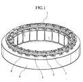
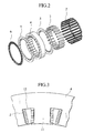
- Fig. 1 is a perspective view of a stator in the rotary electric machine and Fig. 2 is a developed diagram thereof.
- a stator 1 comprises at least stator coils 2 formed by windings of flat type conductors, slot insulating tubes 3, a laminated stator core 4, reinforcing plates 5 positioned on side end faces of the stator core 4 to reinforce the stator core, and a crossover conductor ring 6 for gathering and connecting ends of the stator coils 2.
- the stator core 4 is formed by an integral laminate of many iron sheets, and twenty-four semi-closed slots 12 each having a partially open inside are formed inside the core at equal intervals in the circumferential direction.
- the slot insulating tubes 3 are axially inserted respectively into the twenty-four semi-closed slots 12.
- FIG. 3 eight plate-like (flat type) stator coils 2 each pre-formed in U shape are laminated as one set and in this state are inserted into each of twenty-four slots 12.
- the slots 12 and teeth 11 of the stator core 4 are arranged in an alternate way.
- a concentrated winding of 1Y connection can be constituted by mounting and connection of a crossover conductor ring 6 having inter-phase crossover conductors and neutral conductors.
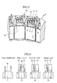
- Fig. 3 is a partial sectional view of the stator 1.
- stator core 4 In an inner periphery portion of the stator core 4 are arranged twenty-four slots 12 at equal intervals in the rotational direction.
- slots 12 In each slot 12 are accommodated eight stator coils 2 in a state such that their wide surfaces are stacked surfaces with respect to the bottom of the slot.
- Fig. 4 shows a state after insertion of the stator coils 2.
- the stator coils 2 each pre-formed in U shape are inserted stackedly into slots so that eight stator coils as one set for each slot.
- Projection sizes k of rectilinear portions at coil ends projecting from each slot 12 are determined at the time of pre-forming the stator coils 2 in U shape so that it is possible to match the heights of adjacent coil ends and connect the coil ends at the time of subjecting the coil ends to forming. These sizes are calculated at the stage of design.
- Fig. 5 shows a state in which end portions of the stator coils 2 have been subjected to forming from the state of Fig. 4.
- Eight stator coils 2 are formed to constitute a coil assembly 40.
- the coil assembly 40 is in contact with another coil assembly adjacent thereto in the circumferential direction.
- a forming tool can be operated from above and within the width of each tooth 11. Actually, coil ends can be subjected to forming in three steps.
- Fig. 6 shows through what steps the coil ends are subjected to forming.
- stator coils 2 Prior to forming, first in a pre-step "Coil Insertion," stator coils 2 are inserted into each slot 12, and thereafter a bending guide 50 which undergoes a forming load is disposed on an upper surface of the tooth 11.
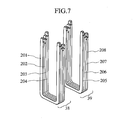
- Fig. 7 shows a state before subjecting the coil assembly 40 to forming.
- the coil assembly 40 is divided to a coil group 38 comprising four U-shaped coils 201, 202, 203, 204, which are laminated together, and a coil group 39 comprising four U-shaped coils 205, 206, 207, 208, which are also laminated together.
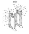
- Fig. 8 shows a state after forming of the coil assembly 40, which forming has been performed by the method illustrated in Fig. 6.
- a winding start end 21 of the U-shaped coil 201 is a rectilinear portion, and in accordance with the method shown in Fig. 6 a winding terminal end 22 is formed to a posture parallel to the winding start end 21 while ensuring an insulating space in the direction of the winding start end 21.
- the forming is performed using the bars 53, 55, and 57 shown on the righthand side in Fig. 6.
- a winding start end 23 of the U-shaped coil 202 adjacent to the winding start end 21 of the U-shaped coil 201 is formed to a position coincident with a side face of the winding terminal end 22 of the coil 201, and a winding end 24 of the coil 202 is formed to a posture parallel to the winding start end 23 of the coil 202 while ensuring an insulating space in the direction of the winding start end 23 of the coil 202.
- the forming is performed using the bars 52, 53, 54, 55, 56, and 57 shown in Fig. 6.
- a winding start end 25 of the U-shaped coil 203 adjacent to the winding start end 23 of the U-shaped coil 202 is formed to a position coincident with a side face of the winding terminal end 24 of the U-shaped coil 202.
- a winding terminal end 26 of the U-shaped coil 203 is formed to a posture parallel to the winding start end 25 of the U-shaped coil 203 while ensuring an insulating space in the direction of the winding start end 25 of the coil 203.
- a winding start end 27 of the U-shaped coil 204 adjacent to the winding start end 25 of the U-shaped coil 203 is formed to a position coincident with a side face of the winding terminal end 26 of the coil 203.
- a winding terminal end 28 of the U-shaped coil 204 is a rectilinear portion and in this case the forming is performed using the bars 52, 54, and 56 shown on the lefthand side in Fig. 6.
- a stator coil group 39 is also formed in the same way. That is, a winding start end 29 of a stator coil is a rectilinear portion, and winding terminal and start ends of adjacent stator coils, i.e., a winding terminal end 30 and a winding start end 31, a winding terminal end 32 and a winding start end 33, a winding terminal end 34 and a winding start end 35, are subjected to forming repeatedly in a successively offset manner in the rotational direction while leaving a space capable of ensuring an insulating space, to constitute a coil group 39 wherein a winding terminal end 36 is a rectilinear portion.
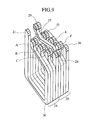
- Fig. 9 shows a state of a one-phase coil assembly. If the winding terminal end 28 of the preceding-stage coil group 38 and the winding start end 29 of the succeeding-stage coil group 39 are connected together through a crossover conductor 37 in a shape such that side faces of the ends coincide with each other, there is constituted a one-phase coil assembly 41 including two coil groups beginning with the winding start end 21 and ending in the winding terminal end 36.
- the crossover conductor 37 is built in the crossover conductor ring 6 and the aforesaid connection is made after mounting the crossover conductor ring 6 has been mounted to the stator core with coils groups built therein.
- preceding-stage coil assemblies 40 are arranged alternately with teeth 11 which are equally divided to twenty-four in the inner periphery direction of the stator core 4.
- stator coils stacked in each slot since the number of stator coils stacked in each slot is eight, four stacked U-shaped coils are used as one coil group and there are adopted three positions in each of which a side face of a preceding-stage winding terminal end and that of a succeeding-stage winding start end coincide with each other.
- An eight-coil assembly is constituted by connecting two coil groups through the crossover conductor.
- each stator coil assembly is composed of plural coil groups, and by connecting a winding start end and a winding terminal end in the respective groups through the crossover conductor it is possible to constitute an assembly of n number (n is a natural number) of stacked stator coils.
- stator coils which are stacked so as to give three coincident positions of side faces of coil ends is 4n (n is a natural number). In case of such positions being four, the number of such stator coils is 5n. Likewise, in case of five such positions, the number of such stator coils is 6n.
- flat type conductors pre-formed in U shape are stacked within each slot 12 formed in the stator core 4 in such a manner that their surfaces perpendicular to the radial direction R of the stator core 4 are wide surfaces W, thereby disposing at least two coils groups 38 and 39.
- a connection A between the winding terminal end 22 of the U-shaped coil 201 and the winding start end 23 of the U-shaped coil 202, a connection B between the winding terminal end 24 of the U-shaped coil 202 and the winding start end 25 of the U-shaped coil 203, and a connection C between the winding terminal end 26 of the U-shaped coil 203 and the winding start end 27 of the U-shaped coil 204, are formed in an offset state so as to ensure a sufficient distance for insulation from one another, that is, for preventing an overlap of those ends.
- the connections A, B, and C are formed so as to be offset from one another by a predetermined distance in a rotational direction.
- a connection D between the winding terminal end 30 of the U-shaped coil 205 and the winding start end 31 of the U-shaped coil 206, a connection E between the winding terminal end 32 of the U-shaped coil 206 and the winding start end 33 of the U-shaped coil 207, and a connection F between the winding terminal end 34 of the U-shaped coil 207 and the winding start end 35 of the U-shaped coil 208, are formed in an offset state so as to ensure a sufficient distance for insulation from one another, that is, for preventing an overlap of those ends.
- connections in the stator coil groups 38 and 39 are formed so that the connections A and D, the connections B and E, and the connections E and C, are respectively positioned on substantially the same direction lines radially and occupy substantially the same positions respectively and so that the distance between the connections A and D, the distance between the connections B and E, and the distance between the connections C and F, are almost equal.
- Fig. 10 shows a connecting method for the coil assembly 40.
- stator coils each having a flat section size of 2.4 mm x 4.5 mm, the length to width ratio becomes approximately 1:2, and if side faces of such coils are abutted against each other, there is formed a coil connection which is generally square in shape of 4.8 mm x 4.5 mm.
- a coil positioning guide 70 is inserted from above to fix the connections A, B, C, D, E, and F, the coil positioning guide 70 having generally square holes formed in positions and sizes corresponding to the connections A, B, C, D, E, and F which positions correspond to the positions of reference numerals 72, 73, 74, 75, 76, and 77).
- a (+) electrode 71 is fixed to the winding start end 21 of the coil group 38, and for the connecting positions 72, 73, and 74 in which side faces of preceding-stage winding terminal ends and side faces of succeeding-stage winding start ends are lapped together, a torch is moved along a torch path 78 to connect coil ends by a continuous operation.
- a (+) electrode 71 is fixed to the winding terminal end 36 of the coil group 39, and for the connecting positions 75, 76, and 77 in which side faces preceding-stage winding terminal ends and side faces of succeeding-stage winding start ends are lapped together, a torch is moved along a torch path 79 to connect coil ends by a continuous operation.
- (+) electrodes 71 are fixed to two hundred and eleven winding start ends, but once the connecting position 72 is connected, a conducting state is created from the winding start end 21 which is in contact with (+) electrode 71 up to the connecting position 73, and upon connection of the connecting position 73 the conducting state reaches the connecting position 74. Consequently, with (+) electrode 71 fixed and by moving the torch, it is possible to effect connection by a continuous operation.
- Fig. 11 is a top view of a coil connector used in the above coil connection.
- the coil connector comprises an index section 91 for performing operation for each coil group, a torch slide section 92 for connecting coil ends continuously by TIG welding, and a (+) electrode fixing section 93.
- the stator 1 is disposed in a direction in which stator coil ends lie on the upper side centrally of the index section 91, the coil groups arranged at equal intervals in the rotational direction are welded by TIG welding, and indexing is repeated to effect connection. At the same time, an electric current fed in the TIG welding is measured to make sure that the connection is effected.
- the coil connector there may be used a known coil connector after an improvement is made thereto.
- Fig. 12 is a partial perspective view showing the surface of the crossover conductor ring 6.
- a ring 61 is formed of an insulating material, and on the surface thereof are arranged twenty-one inter-phase crossover conductors 62 and neutral conductors 63, as well as twenty-four crossover conductors 37.
- Fig. 13 is a partial perspective view showing the back side of the crossover conductor ring 6.
- insulating holes 721, 731, 741, 751, 761, and 771 for ensuring insulation of the connections A, B, C, D, E, and F at the connecting positions 72, 73, 74, 75, 76, and 77 of the coil assembly 40 shown in Fig. 10.
- Also formed in the back side of the crossover conductor ring 6 are through holes 211, 281, 291, and 361 for positioning the rectilinear portions 21, 28, 29, and 36 which are winding start and terminal end portions shown in Fig. 9.
- Fig. 14 illustrates a mounted state of the crossover conductor ring 6.
- the ring 6 is mounted from above to effect insulation of the connections at the connecting positions 72, 73, 74, 75, 76, and 77 of the coil assembly 40 and effect positioning of the rectilinear portions 21, 28, 29, and 36.
- the inter-phase crossover conductors 62, neutral conductors 63, and crossover conductors 37 have an end shape coincident with end side faces of the rectilinear portions 21, 28, 29, and 36 of the stator coil shown in Fig. 9, and by TIG welding after mounting there is constituted a concentrated winding of 1Y.
- Fig. 15 shows a state before connection of lap winding coil ends.
- Stator coils are received in each slot in a state in which wide surfaces of the coils are stacked surfaces with respect to the bottom of the slot, and in this state forming is performed so that a side face 801 of a preceding-stage winding terminal end and a side face 802 of a succeeding-stage winding start end coincide with each other, followed by connection, whereby it is possible to constitute a lap winding.
- coil tips are twisted 90° and forming is performed so that a side face of a preceding-stage winding terminal end and a side face of a succeeding-stage winding start end coincide with each other, whereby there can be attained a connection of a high positional tolerance.
- terminal conductors in a rotary electric machine which uses flat type conductors, but in a relatively small-sized electric device using round or flat type conductors, terminal conductors may be bundled into a circular form and be welded in this form.
- Fig. 16 shows a state of a terminal connection of a round conductor 101.
- a melted portion in spot welding assumes a circular shape under surface tension, so a connection 102 is formed circularly with forming dies 107 and 108.
- connection By forming the connection in a circular shape it is possible to decrease a lack of penetration in a welded portion. For minimizing the resistance of each conductor connection it is necessary to conduct forming so that the sectional area of the connection 102 is equal to or larger than the sectional area of the conductor 101.
- the shape of this terminal connection is suitable for use in an electric device in which round conductors are connected.
- Fig. 17 shows a state of a flat conductor terminal connection
- Fig. 18 shows a state of another flat conductor terminal connection.
- connections 104 and 106 are formed into a circular shape by means of forming dies 107 and 108. By forming the connections circularly it is possible to decrease a lack of penetration in the welding portion. For minimizing the resistance of the conductor connections it is necessary to conduct forming so that the connections 104 and 106 are equal to or larger than the conductors 103 and 105 in sectional area.
- a side face of a preceding-stage winding terminal end and a side face of a succeeding-stage winding start end in laminated coils are connected together in a lapped state, whereby there are attained such effects a high connecting position tolerance, improved connection reliability, simplified terminal processing, and reduction in the number of working steps based on the crossover conducting ring mounting work.
- flat type conductors pre-formed in U shape are inserted into each of slots formed in a stator core in such a manner that wide surfaces of the conductors are stacked surfaces with respect to the bottom of the slot, a side face of a preceding-stage winding terminal end and a side face of a succeeding-stage winding start end in the flat type conductors are connected together in a lapped state to constitute a stator coil assembly. Therefore, it is possible to provide a rotary electric machine having a winging structure not restricted by the shape of core.
- the rotary electric machine since the rotary electric machine has a stator coil assembly with preceding- and succeeding-stage winding terminal and start ends inserted and connected to an insulating ring having pre-laid crossover conductors, it is possible to simplify the terminal processing work and the rotary electric machine exhibits a high assembling work efficiency. Since the length to width ratio of the flat type conductors is set at approximately 1:2, it is possible to provide a rotary electric machine having a high positional tolerance in connection.
- stator coil assembly comprises plural coil groups and the respective winding start and terminal ends are positioned projectingly in the winding direction and are connected through crossover conductors, whereby it is possible to provide a rotary electric machine of a simple structure and exhibiting a high assembling work efficiency.
- the insulating ring is a crossover conductor ring having inter-phase crossover conductors and neutral conductors and through which there are connected the aforesaid winding terminal and start ends, it is possible to provide a rotary electric machine having a higher positional tolerance.
- a rotary electric machine comprising: a stator core; and stator coils inserted into slots formed in the stator core; wherein flat type conductors pre-formed in U shape by molding are disposed in a stacked state within each of the slots of said stator core in such a manner that respective surfaces perpendicular to the radial direction of the stator core are wide surfaces, side faces of preceding-stage winding terminal ends and side faces of succeeding-stage winding start ends of said flat type conductors, which ends are opposed to each other, are connected together in a lapped state to constitute two coils within each said slot, an insulating ring with crossover conductors laid thereon in advance is mounted to said stator core, and the winding terminal end of one said coil and the winding start end of the other coil are connected together through the associated one of said crossover conductors.
- a method for connecting stator conductors wherein a plurality of unconnected conductors are disposed within each of slots formed in a stator core, and one electrode is fixed to a winding start end of said conductors, while another electrode is moved in a successive manner to connect a preceding-stage winding terminal end and a succeeding-stage winding start end of said conductors with each other by conductive heating.
- a method for connecting stator conductors wherein flat type conductors pre-formed in U shape by molding are disposed in a stacked state within each of slots formed in a stator core in such a manner that respective surfaces perpendicular to the radial direction of the stator core are wide surfaces, and one electrode is fixed to a winding start end of said flat type conductors, while another electrode is moved in a successive manner to connect a preceding-stage winding terminal end and a succeeding-stage winding start end of the flat type conductors with each other by conductive heating.
- insulating ring is a crossover conductor ring with inter-phase crossover conductors and neutral conductors laid thereon, and the winding terminal end and the winding start end, both extending through said crossover conductor, are connected together through the associated one of crossover conductors.
- a typical effect of the present invention is that there can be provided a rotary electric machine having a winding structure not restricted by the core shape.
Landscapes
- Engineering & Computer Science (AREA)
- Manufacturing & Machinery (AREA)
- Power Engineering (AREA)
- Windings For Motors And Generators (AREA)
- Manufacture Of Motors, Generators (AREA)
- Insulation, Fastening Of Motor, Generator Windings (AREA)
Abstract
Further, an insulating ring (61) with crossover conductors (37, 62, 63) laid thereon is combined with such stator coil assembly to connect winding terminal and start ends of the stator coil assembly, thereby constituting a predetermined winding circuit.
Description
characterized in that flat type conductors pre-formed in U shape by molding are disposed in a stacked state within each of the slots of the stator core in such a manner that respective surfaces perpendicular to the radial direction of the stator core are wide surfaces, and side faces of preceding-stage winding terminal ends and side faces of succeeding-stage winding start ends of the flat type conductors, which are opposed to each other, are connected together in a lapped state to assemble the stator coils.
Claims (7)
- A rotary electric machine comprising:wherein flat type conductors (201 - 208) pre-formed in U shape by molding are disposed in a stacked state within each of the slots of said stator core in such a manner that respective surfaces perpendicular to the radial direction of the stator core are wide surfaces, and side faces of preceding-stage winding terminal ends (22, 24, 26, 28, 30, 32, 34, 36) and side faces of succeeding-stage winding start ends (21, 23, 25, 27, 29, 31, 33, 35) of said flat type conductors, which ends are opposed to each other, are connected together in a lapped state to assemble the stator coils.a stator core (4); andstator coils (2) inserted into slots (12) formed in the stator core;
- A rotary electric machine according to claim 1, wherein said stator coils each comprising:a plurality of coils (201 - 208) and a winding start end and a winding terminal end of each of the coils are projected in the axial direction of said stator core and are connected together through a crossover conductor (37, 62, 63).
- A rotary electric machine according to claim 1, wherein the connections are formed so as to be offset from one another by a predetermined distance in a rotational direction.
- A rotary electric machine comprising:wherein flat type conductors (201 - 208) pre-formed in U shape by molding are disposed in a stacked state within each of the slots of said stator core in such a manner that respective surfaces perpendicular to the radial direction of the stator core are wide surfaces, to constitute at least two coils disposed within each said slot, and side faces of preceding-stage winding terminal ends (22, 24, 26, 28, 30, 32, 34, 36) and side faces of succeeding-stage winding start ends (21, 23, 25, 27, 29, 31, 33, 35) of said flat type conductors, which ends are opposed to each other, are connected together in a lapped state so that the connections formed successively toward the outer periphery side of the stator core are offset from each other by a predetermined distance in a rotational direction.a stator core (4); andstator coils (2) inserted into slots (12) formed in the stator core;
- A rotary electric machine according to claim 4, wherein the connections formed in said two coils are positioned substantially on the same direction line when looking in the radial direction in a mutually opposed state of the two coils, and the distance between the opposed connections is set substantially equal.
- A method for connecting stator conductors, wherein a plurality of unconnected conductors are disposed within each of slots formed in a stator core, and a preceding-stage winding terminal end and a succeeding-stage winding start end of said plural conductors are bundled and formed into a circular shape, then connected together by welding.
- A method for connecting stator conductors according to claim 6, wherein a sectional area of said conductors formed in a circular shape is equal to or larger than the total sectional area of the bundled conductors.
Applications Claiming Priority (2)
| Application Number | Priority Date | Filing Date | Title |
|---|---|---|---|
| JP2002002915 | 2002-01-10 | ||
| JP2002002915A JP3740421B2 (en) | 2002-01-10 | 2002-01-10 | Connection method between rotating electric machine and stator lead |
Publications (3)
| Publication Number | Publication Date |
|---|---|
| EP1328059A2 true EP1328059A2 (en) | 2003-07-16 |
| EP1328059A3 EP1328059A3 (en) | 2005-04-06 |
| EP1328059B1 EP1328059B1 (en) | 2008-06-11 |
Family
ID=19190802
Family Applications (1)
| Application Number | Title | Priority Date | Filing Date |
|---|---|---|---|
| EP02023631A Expired - Lifetime EP1328059B1 (en) | 2002-01-10 | 2002-10-18 | Rotary electric machine and method for connecting stator conductors |
Country Status (4)
| Country | Link |
|---|---|
| US (1) | US6700282B2 (en) |
| EP (1) | EP1328059B1 (en) |
| JP (1) | JP3740421B2 (en) |
| DE (1) | DE60227041D1 (en) |
Cited By (10)
| Publication number | Priority date | Publication date | Assignee | Title |
|---|---|---|---|---|
| ITTO20110199A1 (en) * | 2011-03-07 | 2012-09-08 | Atop Spa | APPARATUS AND PROCEDURE FOR THE ALIGNMENT OF CONDUCTORS OF COIL ELEMENTS IN DYNAMO ELECTRIC MACHINES TO PERFORM WELDING OPERATIONS. |
| US9479033B2 (en) | 2011-05-16 | 2016-10-25 | Atop S.P.A. | Apparatus and method for manufacturing coil members for cores of dynamo electric machines by bending |
| CN106471717A (en) * | 2014-06-09 | 2017-03-01 | 日产自动车株式会社 | The manufacture method of flat wire stator coil |
| EP3048704A4 (en) * | 2013-09-18 | 2017-06-14 | Mitsubishi Electric Corporation | Rotating electrical machine stator |
| US9692283B2 (en) | 2014-03-07 | 2017-06-27 | Atop S.P.A | Apparatus and method for forming coil members |
| WO2018033761A1 (en) * | 2016-08-19 | 2018-02-22 | Aeristech Ltd | An electric machine and a stator with conductive bars and an end face assembly |
| US10305354B2 (en) | 2013-10-18 | 2019-05-28 | Atop S.P.A. | Apparatus for manufacturing components of dynamoelectric machines |
| US10749418B2 (en) | 2015-04-30 | 2020-08-18 | Atop S.P.A. | Methods for forming woven undulated coil assemblies |
| CN112713723A (en) * | 2020-12-25 | 2021-04-27 | 中车永济电机有限公司 | Radially arranged traction motor conducting ring structure for locomotive |
| US11557946B2 (en) | 2015-07-20 | 2023-01-17 | Atop S.P.A. | Method for inserting undulated coil assemblies in slots of cores of dynamoelectric machines |
Families Citing this family (44)
| Publication number | Priority date | Publication date | Assignee | Title |
|---|---|---|---|---|
| JP3734160B2 (en) * | 2001-12-13 | 2006-01-11 | 株式会社デンソー | Manufacturing method of stator of rotating electric machine |
| JP3630141B2 (en) * | 2002-02-28 | 2005-03-16 | 株式会社デンソー | Manufacturing method of stator of rotating electric machine |
| JP2004048890A (en) * | 2002-07-11 | 2004-02-12 | Denso Corp | Rotating electric machine |
| US6965183B2 (en) * | 2003-05-27 | 2005-11-15 | Pratt & Whitney Canada Corp. | Architecture for electric machine |
| US7583063B2 (en) | 2003-05-27 | 2009-09-01 | Pratt & Whitney Canada Corp. | Architecture for electric machine |
| US7582999B2 (en) * | 2003-11-20 | 2009-09-01 | Intelligent Electric Motor Solutions Pty Ltd | Electric machine having a magnetically inducible core |
| JP4096908B2 (en) | 2004-03-31 | 2008-06-04 | 株式会社豊田自動織機 | Manufacturing method of rotating electrical machine |
| JP4501762B2 (en) * | 2005-04-18 | 2010-07-14 | 株式会社デンソー | Vehicle alternator |
| JP2007006634A (en) * | 2005-06-24 | 2007-01-11 | Hitachi Global Storage Technologies Netherlands Bv | Disk device and disk drive device |
| US7550890B2 (en) * | 2005-08-23 | 2009-06-23 | Seagate Technology Llc | Motor assembly with an integrated flexible printed circuit |
| JP4946421B2 (en) * | 2006-12-20 | 2012-06-06 | 株式会社デンソー | Winding joining method for rotating electrical machines |
| JP2008167604A (en) * | 2006-12-28 | 2008-07-17 | Ichinomiya Denki:Kk | Stator of inner rotor type molded brushless motor |
| JP5161637B2 (en) * | 2007-04-11 | 2013-03-13 | アスモ株式会社 | DC motor |
| JP5097569B2 (en) * | 2008-02-14 | 2012-12-12 | 株式会社日立製作所 | Coil manufacturing method and manufacturing apparatus |
| DE102008022170A1 (en) * | 2008-05-05 | 2009-11-12 | Brose Fahrzeugteile GmbH & Co. Kommanditgesellschaft, Würzburg | Coil for an electric machine and method of manufacturing a coil |
| US8479377B2 (en) * | 2008-10-24 | 2013-07-09 | GM Global Technology Operations LLC | Methods and apparatus for a motor stator |
| US20100148623A1 (en) * | 2008-12-15 | 2010-06-17 | Schlumberger Technology Corporation | High voltage motor windings |
| JP5548377B2 (en) * | 2009-03-31 | 2014-07-16 | 日立オートモティブシステムズ株式会社 | Rotating electric machine |
| TWI392196B (en) * | 2009-06-30 | 2013-04-01 | Victory Ind Corp | Method of Making Stirrups for Automobile Generators |
| JP5417081B2 (en) * | 2009-08-05 | 2014-02-12 | 日立オートモティブシステムズ株式会社 | Rotating electric machine |
| JP5586969B2 (en) * | 2010-01-21 | 2014-09-10 | 株式会社デンソー | Rotating electric machine stator |
| JP5343905B2 (en) * | 2010-03-26 | 2013-11-13 | 株式会社デンソー | Welding and holding device for winding coils of rotating electrical machines |
| US8410653B1 (en) | 2010-06-21 | 2013-04-02 | Christopher Moore | Magnetic lighting circuit and mounting system |
| US8575871B1 (en) | 2010-07-23 | 2013-11-05 | Christopher Moore | Modular component electric machine |
| JP2012139075A (en) * | 2010-12-28 | 2012-07-19 | Hitachi Automotive Systems Ltd | Rotary electric machine |
| JP5516562B2 (en) * | 2011-02-09 | 2014-06-11 | 株式会社豊田自動織機 | Coil, stator and coil manufacturing method |
| US8531075B1 (en) | 2011-06-21 | 2013-09-10 | Christopher Moore | Magnetic electrical contact system |
| JP5389109B2 (en) * | 2011-07-21 | 2014-01-15 | 本田技研工業株式会社 | Rotating electric machine stator |
| US9362809B2 (en) * | 2011-07-21 | 2016-06-07 | Honda Motor Co., Ltd. | Stator for electric rotary machine and fabricating method of the same |
| US20130069474A1 (en) * | 2011-09-16 | 2013-03-21 | Remy Technologies, L.L.C. | Composite conductor insulation |
| US8907540B2 (en) | 2011-11-18 | 2014-12-09 | Remy Technologies, L.L.C. | Electric machine with insulator spacer |
| US8749107B2 (en) | 2011-12-07 | 2014-06-10 | Remy Technologies, L.L.C. | Spacer for supporting conductors in an electric machine |
| JP5789538B2 (en) | 2012-02-14 | 2015-10-07 | 日立オートモティブシステムズ株式会社 | Rotating electric machine and method of manufacturing rotating electric machine |
| JP5838930B2 (en) * | 2012-08-08 | 2016-01-06 | 株式会社豊田自動織機 | Coil and stator |
| JP6116298B2 (en) * | 2013-03-15 | 2017-04-19 | 本田技研工業株式会社 | Arrangement structure of rotating electrical machine unit |
| JP6126897B2 (en) * | 2013-04-24 | 2017-05-10 | 本田技研工業株式会社 | Stator for rotating electrical machine and method for manufacturing the same |
| JP5680137B2 (en) * | 2013-05-13 | 2015-03-04 | 日立オートモティブシステムズ株式会社 | Rotating electric machine |
| US20160126789A1 (en) * | 2014-10-31 | 2016-05-05 | GM Global Technology Operations LLC | Permanent magnet motor |
| JP6226938B2 (en) * | 2015-11-24 | 2017-11-08 | 本田技研工業株式会社 | Rotating electric machine |
| CN109586464B (en) * | 2017-09-29 | 2021-11-12 | 比亚迪股份有限公司 | Stator module, motor and vehicle |
| DE102017129134A1 (en) | 2017-12-07 | 2019-06-13 | Aumann AG | Method for producing an arrangement for a plug-in coil of an electrical machine and arrangement |
| DE102019213474A1 (en) * | 2019-09-05 | 2021-03-11 | Zf Friedrichshafen Ag | Coil with hairpin winding and process for their manufacture |
| US12506378B2 (en) * | 2021-05-07 | 2025-12-23 | Autonetworks Technologies, Ltd. | Multi-phase motor insulating structure and multi-phase motor |
| WO2024216262A1 (en) * | 2023-04-14 | 2024-10-17 | Garner Development Services, Llc | Caseless electric motor with a stationary shaft for marine enviroments |
Family Cites Families (20)
| Publication number | Priority date | Publication date | Assignee | Title |
|---|---|---|---|---|
| CH108795A (en) * | 1924-04-17 | 1925-02-16 | Oerlikon Maschf | Solenoid. |
| US4437230A (en) * | 1982-07-19 | 1984-03-20 | Allied Corporation | Motor having insulationless armature connections |
| JPS60139141A (en) * | 1983-12-26 | 1985-07-23 | Hitachi Ltd | Armature winding of rotary electric machine |
| JPH05308742A (en) * | 1992-04-28 | 1993-11-19 | Yaskawa Electric Corp | Stator winding connection method |
| JPH06209535A (en) * | 1993-01-07 | 1994-07-26 | Toyota Motor Corp | Motor coil structure |
| CN1200591A (en) * | 1997-05-26 | 1998-12-02 | 株式会社电装 | car generator |
| JP3769990B2 (en) * | 1999-08-06 | 2006-04-26 | 株式会社デンソー | Conductor segment bonding type rotating electrical machine and method for manufacturing the same |
| JPH11187598A (en) * | 1997-12-22 | 1999-07-09 | Fanuc Ltd | Armature winding for motor |
| JP3384337B2 (en) * | 1998-09-07 | 2003-03-10 | 株式会社デンソー | Stator of vehicle alternator |
| JP3303854B2 (en) * | 1998-09-22 | 2002-07-22 | 株式会社デンソー | Joint wire and joining method |
| JP3508650B2 (en) * | 1998-11-25 | 2004-03-22 | 株式会社デンソー | Rotating machine stator |
| JP3407675B2 (en) * | 1998-11-26 | 2003-05-19 | 株式会社デンソー | Stator of vehicle alternator and vehicle alternator using the same |
| JP3104700B1 (en) * | 1999-03-30 | 2000-10-30 | 株式会社デンソー | Method and apparatus for joining windings of rotating electric machine |
| JP4450124B2 (en) * | 1999-06-25 | 2010-04-14 | 株式会社デンソー | Rotating electric machine and manufacturing method thereof |
| JP3419721B2 (en) * | 1999-12-06 | 2003-06-23 | 三菱電機株式会社 | AC generator for vehicles |
| JP3659874B2 (en) * | 2000-01-31 | 2005-06-15 | 株式会社日立製作所 | Rotating electric machine stator |
| US6548933B2 (en) * | 2000-01-31 | 2003-04-15 | Hitachi, Ltd. | Stator of rotating electric machine |
| FR2808935B1 (en) * | 2000-05-11 | 2002-06-28 | Valeo Equip Electr Moteur | STATOR OF ROTATING ELECTRIC MACHINE AND ALTERNATOR COMPRISING SUCH A STATOR |
| JP4187914B2 (en) * | 2000-08-29 | 2008-11-26 | 三菱電機株式会社 | Rotating electric machine stator |
| JP3586186B2 (en) * | 2000-11-15 | 2004-11-10 | 株式会社日立製作所 | Rotating machine stator |
-
2002
- 2002-01-10 JP JP2002002915A patent/JP3740421B2/en not_active Expired - Fee Related
- 2002-10-18 DE DE60227041T patent/DE60227041D1/en not_active Expired - Fee Related
- 2002-10-18 EP EP02023631A patent/EP1328059B1/en not_active Expired - Lifetime
- 2002-10-30 US US10/283,273 patent/US6700282B2/en not_active Expired - Fee Related
Cited By (22)
| Publication number | Priority date | Publication date | Assignee | Title |
|---|---|---|---|---|
| US10224789B2 (en) | 2011-03-07 | 2019-03-05 | Atop S.P.A. | Apparatus for aligning conductors of coil members in cores of electric dynamo machines |
| WO2012119691A1 (en) * | 2011-03-07 | 2012-09-13 | Atop S.P.A. | Apparatus and method for aligning conductors of coil members in cores of elecric dynamic machines prior to welding operations |
| CN103518316A (en) * | 2011-03-07 | 2014-01-15 | 阿拓普股份公司 | Apparatus and method for aligning conductors of coil members in cores of elecric dynamic machines prior to welding operations |
| CN103518316B (en) * | 2011-03-07 | 2016-04-06 | 阿拓普股份公司 | The equipment making the conductor of the coil member in electric motor core aim at before welding and method |
| US9455614B2 (en) | 2011-03-07 | 2016-09-27 | Atop S.P.A. | Method for aligning conductors of coil members |
| ITTO20110199A1 (en) * | 2011-03-07 | 2012-09-08 | Atop Spa | APPARATUS AND PROCEDURE FOR THE ALIGNMENT OF CONDUCTORS OF COIL ELEMENTS IN DYNAMO ELECTRIC MACHINES TO PERFORM WELDING OPERATIONS. |
| US10411570B2 (en) | 2011-05-16 | 2019-09-10 | Atop S.P.A. | Apparatus for manufacturing coil members for cores of dynamo electric machines by bending |
| US9479033B2 (en) | 2011-05-16 | 2016-10-25 | Atop S.P.A. | Apparatus and method for manufacturing coil members for cores of dynamo electric machines by bending |
| EP3048704A4 (en) * | 2013-09-18 | 2017-06-14 | Mitsubishi Electric Corporation | Rotating electrical machine stator |
| US10305354B2 (en) | 2013-10-18 | 2019-05-28 | Atop S.P.A. | Apparatus for manufacturing components of dynamoelectric machines |
| US9692283B2 (en) | 2014-03-07 | 2017-06-27 | Atop S.P.A | Apparatus and method for forming coil members |
| CN106471717A (en) * | 2014-06-09 | 2017-03-01 | 日产自动车株式会社 | The manufacture method of flat wire stator coil |
| CN106471717B (en) * | 2014-06-09 | 2018-12-07 | 日产自动车株式会社 | Manufacturing method of flat wire stator coil |
| EP3154159A4 (en) * | 2014-06-09 | 2017-04-12 | Nissan Motor Co., Ltd | Flat-wire stator coil manufacturing method |
| US9825513B2 (en) | 2014-06-09 | 2017-11-21 | Nissan Motor Co., Ltd. | Rectangular wire stator coil manufacturing method |
| US10749418B2 (en) | 2015-04-30 | 2020-08-18 | Atop S.P.A. | Methods for forming woven undulated coil assemblies |
| US11336160B2 (en) | 2015-04-30 | 2022-05-17 | Atop S.Pa. | Methods for forming woven undulated coil assemblies |
| US11658553B2 (en) | 2015-04-30 | 2023-05-23 | Atop S.P.A. | Apparatuses for forming woven undulated coil assemblies |
| US11557946B2 (en) | 2015-07-20 | 2023-01-17 | Atop S.P.A. | Method for inserting undulated coil assemblies in slots of cores of dynamoelectric machines |
| US12470114B2 (en) | 2015-07-20 | 2025-11-11 | Atop S.P.A. | Apparatus for inserting an undulated coil assembly in slots of a core of a stator of a dynamoelectric machine |
| WO2018033761A1 (en) * | 2016-08-19 | 2018-02-22 | Aeristech Ltd | An electric machine and a stator with conductive bars and an end face assembly |
| CN112713723A (en) * | 2020-12-25 | 2021-04-27 | 中车永济电机有限公司 | Radially arranged traction motor conducting ring structure for locomotive |
Also Published As
| Publication number | Publication date |
|---|---|
| JP3740421B2 (en) | 2006-02-01 |
| DE60227041D1 (en) | 2008-07-24 |
| EP1328059B1 (en) | 2008-06-11 |
| JP2003204647A (en) | 2003-07-18 |
| EP1328059A3 (en) | 2005-04-06 |
| US6700282B2 (en) | 2004-03-02 |
| US20030127935A1 (en) | 2003-07-10 |
Similar Documents
| Publication | Publication Date | Title |
|---|---|---|
| US6700282B2 (en) | Rotary electric machine and method for connecting stator conductors | |
| US7126246B2 (en) | Rotary electric machine with stator having an annular array of poles | |
| EP1122861B1 (en) | Stator windings of an alternator | |
| US8581460B2 (en) | Armature for rotating electrical machine | |
| US5508571A (en) | Neutral connection for wire wound stator | |
| KR100433998B1 (en) | Stator and stator core for a dynamoelectric machine and a method for manufacture thereof | |
| US8674577B2 (en) | Stator for electric rotating machine | |
| CN106612020B (en) | The stator of rotating electric machine | |
| US6938323B2 (en) | Method of manufacturing stator coil of rotary electric machine | |
| CN110235342A (en) | Stator for motor | |
| US12142416B2 (en) | Electric motor, motor vehicle, and method for producing a winding for an electric motor | |
| CN110176813B (en) | Stator of rotating electric machine | |
| US20190013704A1 (en) | Stator for rotary electric machine | |
| CN115461961B (en) | Stator coil and stator of rotating electrical machine | |
| US7026735B2 (en) | Stator of rotating electric machine | |
| US20190013720A1 (en) | Stator for rotary electric machine | |
| WO2021231580A1 (en) | Stator with internal connections for winding leads | |
| JP3310971B2 (en) | AC generator manufacturing method | |
| WO2012011352A1 (en) | Dynamo-electric machine armature | |
| JP2000069700A (en) | Multi-phase wave winding of rotating electric machine | |
| JP7465170B2 (en) | Windings of electromagnetic components, stators of rotating electrical machines, rotating electrical machines and wheels | |
| JP2003333782A (en) | Rotating electric machine | |
| JP2003274594A (en) | Rotating machine stator | |
| JP2019118249A (en) | Stator and electric motor | |
| US7777390B2 (en) | Short-circuit member assembly, commutator, and motor |
Legal Events
| Date | Code | Title | Description |
|---|---|---|---|
| PUAI | Public reference made under article 153(3) epc to a published international application that has entered the european phase |
Free format text: ORIGINAL CODE: 0009012 |
|
| AK | Designated contracting states |
Designated state(s): AT BE BG CH CY CZ DE DK EE ES FI FR GB GR IE IT LI LU MC NL PT SE SK TR |
|
| AX | Request for extension of the european patent |
Extension state: AL LT LV MK RO SI |
|
| PUAL | Search report despatched |
Free format text: ORIGINAL CODE: 0009013 |
|
| AK | Designated contracting states |
Kind code of ref document: A3 Designated state(s): AT BE BG CH CY CZ DE DK EE ES FI FR GB GR IE IT LI LU MC NL PT SE SK TR |
|
| AX | Request for extension of the european patent |
Extension state: AL LT LV MK RO SI |
|
| 17P | Request for examination filed |
Effective date: 20050728 |
|
| AKX | Designation fees paid |
Designated state(s): DE FR GB IT |
|
| 17Q | First examination report despatched |
Effective date: 20060209 |
|
| GRAP | Despatch of communication of intention to grant a patent |
Free format text: ORIGINAL CODE: EPIDOSNIGR1 |
|
| GRAS | Grant fee paid |
Free format text: ORIGINAL CODE: EPIDOSNIGR3 |
|
| GRAA | (expected) grant |
Free format text: ORIGINAL CODE: 0009210 |
|
| RAP1 | Party data changed (applicant data changed or rights of an application transferred) |
Owner name: HITACHI CAR ENGINEERING CO., LTD. Owner name: HITACHI, LTD. |
|
| AK | Designated contracting states |
Kind code of ref document: B1 Designated state(s): DE FR GB IT |
|
| REG | Reference to a national code |
Ref country code: GB Ref legal event code: FG4D |
|
| REF | Corresponds to: |
Ref document number: 60227041 Country of ref document: DE Date of ref document: 20080724 Kind code of ref document: P |
|
| PLBE | No opposition filed within time limit |
Free format text: ORIGINAL CODE: 0009261 |
|
| STAA | Information on the status of an ep patent application or granted ep patent |
Free format text: STATUS: NO OPPOSITION FILED WITHIN TIME LIMIT |
|
| 26N | No opposition filed |
Effective date: 20090312 |
|
| GBPC | Gb: european patent ceased through non-payment of renewal fee |
Effective date: 20081018 |
|
| REG | Reference to a national code |
Ref country code: FR Ref legal event code: ST Effective date: 20090630 |
|
| PG25 | Lapsed in a contracting state [announced via postgrant information from national office to epo] |
Ref country code: IT Free format text: LAPSE BECAUSE OF FAILURE TO SUBMIT A TRANSLATION OF THE DESCRIPTION OR TO PAY THE FEE WITHIN THE PRESCRIBED TIME-LIMIT Effective date: 20080611 Ref country code: DE Free format text: LAPSE BECAUSE OF NON-PAYMENT OF DUE FEES Effective date: 20090501 |
|
| PG25 | Lapsed in a contracting state [announced via postgrant information from national office to epo] |
Ref country code: FR Free format text: LAPSE BECAUSE OF NON-PAYMENT OF DUE FEES Effective date: 20081031 |
|
| PG25 | Lapsed in a contracting state [announced via postgrant information from national office to epo] |
Ref country code: GB Free format text: LAPSE BECAUSE OF NON-PAYMENT OF DUE FEES Effective date: 20081018 |