EP1327898A1 - Optical fiber with a complex index profile in form of a ring structure - Google Patents
Optical fiber with a complex index profile in form of a ring structure Download PDFInfo
- Publication number
- EP1327898A1 EP1327898A1 EP02293230A EP02293230A EP1327898A1 EP 1327898 A1 EP1327898 A1 EP 1327898A1 EP 02293230 A EP02293230 A EP 02293230A EP 02293230 A EP02293230 A EP 02293230A EP 1327898 A1 EP1327898 A1 EP 1327898A1
- Authority
- EP
- European Patent Office
- Prior art keywords
- fiber
- chromatic dispersion
- index
- wavelength
- steps
- Prior art date
- Legal status (The legal status is an assumption and is not a legal conclusion. Google has not performed a legal analysis and makes no representation as to the accuracy of the status listed.)
- Withdrawn
Links
Images

Classifications
-
- G—PHYSICS
- G02—OPTICS
- G02B—OPTICAL ELEMENTS, SYSTEMS OR APPARATUS
- G02B6/00—Light guides; Structural details of arrangements comprising light guides and other optical elements, e.g. couplings
- G02B6/02—Optical fibres with cladding with or without a coating
- G02B6/02004—Optical fibres with cladding with or without a coating characterised by the core effective area or mode field radius
- G02B6/02009—Large effective area or mode field radius, e.g. to reduce nonlinear effects in single mode fibres
- G02B6/02014—Effective area greater than 60 square microns in the C band, i.e. 1530-1565 nm
- G02B6/02019—Effective area greater than 90 square microns in the C band, i.e. 1530-1565 nm
-
- G—PHYSICS
- G02—OPTICS
- G02B—OPTICAL ELEMENTS, SYSTEMS OR APPARATUS
- G02B6/00—Light guides; Structural details of arrangements comprising light guides and other optical elements, e.g. couplings
- G02B6/02—Optical fibres with cladding with or without a coating
- G02B6/02004—Optical fibres with cladding with or without a coating characterised by the core effective area or mode field radius
- G02B6/02009—Large effective area or mode field radius, e.g. to reduce nonlinear effects in single mode fibres
-
- G—PHYSICS
- G02—OPTICS
- G02B—OPTICAL ELEMENTS, SYSTEMS OR APPARATUS
- G02B6/00—Light guides; Structural details of arrangements comprising light guides and other optical elements, e.g. couplings
- G02B6/02—Optical fibres with cladding with or without a coating
- G02B6/02214—Optical fibres with cladding with or without a coating tailored to obtain the desired dispersion, e.g. dispersion shifted, dispersion flattened
- G02B6/02219—Characterised by the wavelength dispersion properties in the silica low loss window around 1550 nm, i.e. S, C, L and U bands from 1460-1675 nm
- G02B6/02228—Dispersion flattened fibres, i.e. having a low dispersion variation over an extended wavelength range
- G02B6/02238—Low dispersion slope fibres
- G02B6/02242—Low dispersion slope fibres having a dispersion slope <0.06 ps/km/nm2
-
- G—PHYSICS
- G02—OPTICS
- G02B—OPTICAL ELEMENTS, SYSTEMS OR APPARATUS
- G02B6/00—Light guides; Structural details of arrangements comprising light guides and other optical elements, e.g. couplings
- G02B6/02—Optical fibres with cladding with or without a coating
- G02B6/02214—Optical fibres with cladding with or without a coating tailored to obtain the desired dispersion, e.g. dispersion shifted, dispersion flattened
- G02B6/02219—Characterised by the wavelength dispersion properties in the silica low loss window around 1550 nm, i.e. S, C, L and U bands from 1460-1675 nm
- G02B6/02266—Positive dispersion fibres at 1550 nm
- G02B6/02271—Non-zero dispersion shifted fibres, i.e. having a small positive dispersion at 1550 nm, e.g. ITU-T G.655 dispersion between 1.0 to 10 ps/nm.km for avoiding nonlinear effects
-
- G—PHYSICS
- G02—OPTICS
- G02B—OPTICAL ELEMENTS, SYSTEMS OR APPARATUS
- G02B6/00—Light guides; Structural details of arrangements comprising light guides and other optical elements, e.g. couplings
- G02B6/02—Optical fibres with cladding with or without a coating
- G02B6/02214—Optical fibres with cladding with or without a coating tailored to obtain the desired dispersion, e.g. dispersion shifted, dispersion flattened
- G02B6/0228—Characterised by the wavelength dispersion slope properties around 1550 nm
-
- G—PHYSICS
- G02—OPTICS
- G02B—OPTICAL ELEMENTS, SYSTEMS OR APPARATUS
- G02B6/00—Light guides; Structural details of arrangements comprising light guides and other optical elements, e.g. couplings
- G02B6/02—Optical fibres with cladding with or without a coating
- G02B6/036—Optical fibres with cladding with or without a coating core or cladding comprising multiple layers
- G02B6/03605—Highest refractive index not on central axis
- G02B6/03611—Highest index adjacent to central axis region, e.g. annular core, coaxial ring, centreline depression affecting waveguiding
-
- G—PHYSICS
- G02—OPTICS
- G02B—OPTICAL ELEMENTS, SYSTEMS OR APPARATUS
- G02B6/00—Light guides; Structural details of arrangements comprising light guides and other optical elements, e.g. couplings
- G02B6/02—Optical fibres with cladding with or without a coating
- G02B6/036—Optical fibres with cladding with or without a coating core or cladding comprising multiple layers
- G02B6/03616—Optical fibres characterised both by the number of different refractive index layers around the central core segment, i.e. around the innermost high index core layer, and their relative refractive index difference
- G02B6/03688—Optical fibres characterised both by the number of different refractive index layers around the central core segment, i.e. around the innermost high index core layer, and their relative refractive index difference having 5 or more layers
-
- G—PHYSICS
- G02—OPTICS
- G02B—OPTICAL ELEMENTS, SYSTEMS OR APPARATUS
- G02B6/00—Light guides; Structural details of arrangements comprising light guides and other optical elements, e.g. couplings
- G02B6/02—Optical fibres with cladding with or without a coating
- G02B6/02214—Optical fibres with cladding with or without a coating tailored to obtain the desired dispersion, e.g. dispersion shifted, dispersion flattened
- G02B6/02219—Characterised by the wavelength dispersion properties in the silica low loss window around 1550 nm, i.e. S, C, L and U bands from 1460-1675 nm
- G02B6/02223—Dual window fibres, i.e. characterised by dispersion properties around 1550 nm and in at least another wavelength window, e.g. 1310 nm
Definitions
- the present invention relates to the field of fiber transmissions optical, and more specifically, the characteristics of the optical fibers used in transmission systems.
- the index profile is generally qualified in function of the shape of the graph of the function which associates with the radius of the fiber the index of refraction.
- index profile in "echelon”, “trapezoid” or “triangle” for graphs that have shapes respective echelon, trapezoid or triangle.
- These curves are generally representative of the theoretical or target profile of the fiber, the constraints of fiber manufacturing can lead to a significantly different profile.
- chromatic dispersion in particular for bit rates greater than or equal to 40 Gbit / s or 160 Gbit / s;
- the objective is to obtain, for all the wavelength values of the multiplex, a dispersion cumulated chromaticity substantially zero on the link, so as to limit widening of impulses.
- a cumulative value of a few tens of ps / nm for dispersion is generally acceptable.
- It is also interesting to limit the cumulative chromatic dispersion slope over the range of the multiplex so as to avoid or limit the distortions between the channels of the multiplex; this is all the more important that the number of channels increases.
- This dispersion slope is conventionally the derivative of the chromatic dispersion with respect to the length wave.
- the amplitude of the non-linear effects in a fiber is inversely proportional to the effective area of the fiber.
- the effective surface should therefore ideally be chosen as high as possible to limit non-linear effects.
- some non-linear effects, such as Raman effect are useful for improving the margins of transmission systems.
- index hopping fibers also called SMF fibers (acronym for "Single Mode Fiber”).
- SMF fibers single Mode Fiber
- the Applicant thus markets under reference Alcatel 6900 a single mode fiber with index jump having a wavelength ⁇ 0 for canceling the chromatic dispersion between 1300 and 1320 nm, and a chromatic dispersion less than or equal to 3.5 ps / (nm.km) in a range of 1285-1330 nm, and of the order of 17 ps / (nm.km) at 1550 nm.
- the chromatic dispersion slope at 1550 nm is of the order of 0.06 ps / (nm 2 .km).
- This fiber typically has a C / C 'ratio of the chromatic dispersion to the chromatic dispersion slope of between 250 and 370 nm at 1550 nm.
- This fiber has an effective surface at 1550 nm close to 80 ⁇ m 2 .
- the ratio of the square of the effective surface to the chromatic dispersion slope is of the order of 107,000 ⁇ m 4 .nm 2 .km / ps.
- Such a fiber has a simple profile, with a single rung; it has an index profile with a central part of index substantially constant and greater than the index of the sheath.
- NZ-DSF + (acronym for "non-zero dispersion shifted fibers") is called fibers with offset dispersion, having a non-zero chromatic dispersion and positive for the wavelengths at which they are used, typically around 1550 nm. These fibers have a low chromatic dispersion for these wavelengths, typically less than 11 ps / (nm.km) at 1550 nm, and a chromatic dispersion slope between 0.04 and 0.1 ps / (nm 2 .km) .
- FR-A-99 02 028 proposes a line fiber, very particularly suitable for a transmission with multiplexing in dense wavelengths, with a spacing between the channels of 100 GHz or less for a bit rate per channel of 10 Gbit / s; this fiber has an effective surface greater than or equal to 60 ⁇ m 2 for a wavelength of 1550 nm, a chromatic dispersion of between 6 and 10 ps / (nm.km), and a chromatic dispersion slope of less than 0.07 ps / (nm 2 .km).
- the Applicant markets under the reference TeraLight a fiber which exhibits at 1550 nm a typical chromatic dispersion C of 8 ps / (nm.km) and a chromatic dispersion slope C 'of 0.058 ps / (nm 2 .km).
- This fiber has an effective area S eff of the order of 65 ⁇ m 2 , and a ratio of the square of the effective area to the chromatic dispersion slope which is of the order of 73,000 ⁇ m 4 .nm 2 .km / ps , at a wavelength of 1550 nm.
- FR-A-00 02 316 describes an optical fiber which is used as line fiber, and whose chromatic dispersion is compensated for by dispersion compensation fiber conventionally used for an index hopping fiber.
- This fiber has a chromatic dispersion between 5 and 11 ps / (nm.km) for a wavelength of 1550 nm, a ratio between the chromatic dispersion and the chromatic dispersion slope between 250 and 370 nm, an effective surface at less than 50 ⁇ m 2 . It is proposed in this document that the ratio between the square of the effective area and the chromatic dispersion slope be greater than 80,000 ⁇ m 4 .nm 2 .km / ps.
- This ratio is in fact representative of the compromise between the effective area - which should be as large as possible - and the chromatic dispersion slope - which should be as small as possible.
- the fibers proposed in this document have a three-step profile with a central rectangle part surrounded by a buried part and a ring.
- WO-A-99 08 142 describes a fiber with high negative chromatic dispersion, presenting a complex profile.
- the invention provides an optical fiber having a profile set point index with more than six steps and positive chromatic dispersion at a wavelength of 1550 nm.
- the invention proposes, to improve the propagation characteristics of state-of-the-art fibers, to provide a setpoint index profile presenting a number of steps greater than or equal to six. More specifically, compared to fibers of the state of the art, the invention proposes to replace the values index constants in a given region by a plurality of index values in this same range; this increase in the number of discrete index values in the fiber allows better choice of the optical characteristics of the fiber. We can also vary the position in the fiber of the index steps, in particular by depending on the manufacturing process used.
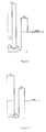
- the fiber Around the first annular part, the fiber has a buried part of index lower than that of the sheath, then a second annular part of index higher than that of the sheath, forming a ring around the coaxial profile.
- Figure 1 show this profile.
- ⁇ n 0 the difference between the index of the buried central part and the index of the fiber cladding
- ⁇ n 1 the difference between the index of the central part and the cladding index of the fiber
- ⁇ n 2 the difference between the index of the buried trench and the index of the fiber cladding
- ⁇ n 3 the difference between the index of the ring and the index of the fiber cladding.
- the fiber of the state of the art in FIG. 1 can have the values of index (expressed in% relative to the index of silica) and of radii proposed in table 1 below, with the notations specified. just now. at 0 [ ⁇ m] at 1 [ ⁇ m] a 2 [ ⁇ m] at 3 [ ⁇ m] ⁇ n 0 [%] ⁇ n 1 [%] ⁇ n 2 [%] ⁇ n 3 [%] 1.0 4.0 6.3 7.9 -0.1 0.95 -0.1 0.4
- the fiber of Figure 1 has the optical characteristics given in Table 2; we denote S eff the effective surface, C 'the chromatic dispersion slope, S eff 2 / C' the ratio of the square of the effective surface to the chromatic dispersion slope, ⁇ 0 the wavelength of cancellation of the dispersion chromatic and 2W 02 the mode diameter.
- S eff the effective surface
- C the chromatic dispersion slope
- S eff 2 / C' the ratio of the square of the effective surface to the chromatic dispersion slope
- ⁇ 0 the wavelength of cancellation of the dispersion chromatic
- 2W 02 the mode diameter.
- the four index "steps" of this fiber - corresponding to the first buried trench, to the first annular part, to the second buried trench and to the ring - have been replaced by six or more steps.
- Table 3 below gives the characteristics of the profiles envisaged, while Table 4 provides the propagation characteristics, with the same conventions as Table 2.
- a represents the core radius of the fiber, ie the radius of the part of the fiber extending inside the sheath of constant index.
- the number of steps in the examples in Table 3 varies between 6 and 10. Each step has a constant thickness, which is equal to the ratio between the core radius a and the number of steps in the example.
- the core radius a remains constant, so as to clearly demonstrate the influence of the number of steps. It would of course remain possible to also modify the core radius, at the same time, while modifying the number of steps.
- the core of the fiber remains defined as the central part of the fiber, in which the index is lower or higher than the index of the cladding. This core can be defined, according to the examples, by at least 6 steps.
- Table 4 show that the increase in the number of steps makes it possible to optimize the propagation parameters of the fiber.
- the effective area is in all examples greater than in the fiber of the prior art, while the chromatic dispersion slope is lower. As a result, the ratio of the square of the effective area to the chromatic dispersion slope increases.
- this report presents values greater than 90,000 ⁇ m 4 .nm 2 .km / ps, to be compared with the value of 73,000 ⁇ m 4 .nm 2 .km / ps of the fiber of the state of the technical.
- the chromatic dispersion, the wavelength ⁇ 0 for canceling the chromatic dispersion and the mode diameter of the fiber remain close to the initial values proposed in the prior art.
- Tables 3 and 4 show that increasing the number of steps in the fiber, to reach 6 or more steps, makes it possible to improve the propagation characteristics of the fiber. It will be noted that the transition from 6 steps to 10 is accompanied by an increase in the ratio S eff 2 / C ', and by a decrease in the chromatic dispersion slope. These effects are only caused by the change in the number of steps, the core radius of the fiber remaining constant, for the purposes of the demonstration.
- the fiber of the prior art considered is a zero dispersion fiber (All optical regeneration: key features and application to a 160 Gbit / s (4x40 Gbit / s) long-haul transmission, O. Leclerc et al., LEOS, Vol 14, N ° 4, August 2000).
- This fiber has a reference index profile of the type represented in FIG. 2.
- the values of the radii and of the indices are provided in table 5 below. at 0 [ ⁇ m] at 1 [ ⁇ m] a 2 [ ⁇ m] ⁇ n 0 [x10 3 ] ⁇ n 1 [x10 3 ] ⁇ n 2 [x10 3 ] 2.98 5.64 8.05 8.6 -3.7 3.0
- Table 6 gives with the same notations as Tables 2 and 4 the values of the propagation parameters of the fiber of the state of the art; the values of the chromatic dispersion C, in ps / (nm.km), of the effective cut-off wavelength ⁇ ceff expressed in nm, of the ratio of the chromatic dispersion to the slope of chromatic dispersion, expressed in nm, and losses by bending. These are measured on the one hand by winding the fiber around a 20 mm diameter sleeve; in this case, the linear losses induced by the winding of the fiber are measured.
- Figure 3 is a schematic representation of the profile set point index, in the case of a 10-step fiber.
- the index profile of the fiber remains similar to that of the Figure 2, with a central part of index higher than that of the sheath, a trench of index lower than that of the sheath, then a ring of index higher than that of sheath.
- the trench as in the ring the index varies instead of presenting, as in Figure 2, a constant value.
- the central part consists of three index steps; the buried trench is formed by two index steps, the ring includes three index rungs and the second buried trench consists of two rungs index.
- the fibers proposed in the examples have different profiles, with in particular one or more external steps with an index lower than that sheath.
- each step of the fiber corresponds to a same thickness. This choice simplifies the manufacture of the fiber, each step can then correspond in the manufacture of a preform by VAD or MCVD to one (or more) passes of a blowtorch (VAD or MCVD).
- the parameters of the target profile of the different fibers appear; since the rungs have the same thickness, the table only shows the total radius of the fiber. The thickness of a rung is then obtained by dividing this total radius by the number of rungs. In the first column of this table therefore appears the outer radius a of the second buried trench, expressed in micrometers. Each index step has a thickness which is substantially equal to the ratio of this external radius by the number of steps. The other columns of the table provide the difference between the index of a step and the cladding index, multiplied by 10 3 .
- Examples 1a and 2a are six-step fibers; Examples 3a and 4a of the seven-step fibers; Examples 5a and 6a of 8-step fibers; Examples 7a and 8a of the 9-step fibers, and Examples 9a and 10a of the 10-step fibers.
- n steps with n an integer between 6 and 10 and a thickness of each rung equal to the ratio of the total thickness of the fiber to number of steps is the simplest solution for manufacturing the next fiber a process for successively depositing the different layers forming the preform from from which the fiber can be drawn.
- MCVD modified chemical vapor deposition
- VAD axial vapor deposition "in English).
- Table 8 indicates the optical characteristics of the fibers in Table 7, with the same notations as in Table 6.
- the table shows that the fiber of the invention, in the different examples, has a greater effective area S eff than that of the fiber of the prior art, a similar chromatic dispersion C, a lower dispersion slope C ' , a similar cut-off wavelength ⁇ ceff , a better ratio of the square of the effective area to the chromatic dispersion slope and similar curvature losses.
- the comparison shows that the fiber of the invention presents from the point of view propagation of optical characteristics better than those of fiber the state of the art. This is notably due to better optimization of the fiber by choosing a higher number of steps.
- the different values of the chromatic dispersion show that the fiber of the invention can adapt to different uses, depending on the desired chromatic dispersion.
- a third example of implementation of the invention is described.
- a fiber of the state of the art which corresponds to example B of the request FR-A-00 02 316.
- the fiber has a profile index profile similar to that of Figure 2, and we use in the following description the same notations as above.
- Table 9 gives the characteristics of the fiber of the state of the art, with the same notations as Table 5. at 0 [ ⁇ m] at 1 [ ⁇ m] a 2 [ ⁇ m] ⁇ n 0 [x10 3 ] ⁇ n 1 [x10 3 ] ⁇ n 2 [x10 3 ] 3.56 5.74 10.94 7.1 -6.4 1.1
- the fiber of the state of the art has the propagation characteristics given in table 10, with the same notations as in table 6.
- Table 11 is similar to Table 7 and shows possible values of the index for different fibers of the invention, with the same notations; however, the table includes three examples with eight steps, three examples with nine steps, and four examples with 10 steps.
- Table 12 is similar to Table 8 and has the same notations; it indicates the optical characteristics of the fibers in Table 11.
- the fibers of the invention have, relative to the fiber of the state of the art used for comparison, a greater effective area S eff , a lower dispersion slope C ', and above all a better ratio of the square of the effective area to the chromatic dispersion slope.
- Tables 13 to 16 also provide examples of fibers according to the invention, with different profiles; the ratings are the same as in the previous tables.
- the corresponding fibers have chromatic dispersion values close to 5 and 10 ps / (nm.km) respectively.
- the propagation characteristics of the fibers having the target profile of table 13 are provided in table 14, while the propagation characteristics of the fibers having the target profile of table 15 are provided in table 16.
- the various examples proposed show that the invention allows to improve the characteristics of the fibers of the prior art, by using simply and judiciously the possibilities offered by manufacturing technology preforms.
- a prior art fiber for example a fiber with three steps, as proposed above.
- an optimization program can be used; the values to be optimized are the index values and the radii of the different steps; the starting values are the values corresponding to the profile of the state of the art, as we have just seen mention.
- the optimization parameter which can be a scalar or a vector, is as a function of the propagation characteristics of the fiber.
- Optimization can be performed with optimization tools based on optimization algorithms known per se: Simplex, Conjugated Gradients, Quasi-Newton and genetic algorithm.
- the initial values are chosen from the fibers of the state of the art used for comparison, by cutting the profile into a number of rungs of the same thickness.
- the optimization parameter is the ratio between the square of the effective area and the chromatic dispersion slope.
- the fiber has a positive chromatic dispersion at a wavelength of 1550 nm; this allows it to be used as line fiber in a fiber optic transmission system. It is also advantageous for the fiber to have, at a wavelength of 1550 nm, a chromatic dispersion slope less than or equal to 0.08 ps / (nm 2 .km).
- the marker on the slope of the chromatic dispersion ensures good performance from a system point of view by guaranteeing a reduced variation of the dispersion over a wide spectral band.
- Tables 7-8 (0 ⁇ C ⁇ 1 ps / (nm.km)) and 11-12 (C ⁇ 8 ps / (nm.km)) check these constraints on the chromatic dispersion as on the chromatic dispersion slope.
- the fiber has a low chromatic dispersion - as in the fiber of the state of the art of Tables 5 and 6; this corresponds to fibers optimized for managed solitons dispersed and used for long distance transmissions, such as submarine transmissions.
- a chromatic dispersion close to 8 ps / (nm.km), as in the fibers in Tables 9 to 12 corresponds to a optimization for 40 Gbit / s transmissions.
- the chromatic dispersion at 1550 nm is less than 14 ps / (nm.km). Above this terminal, it is also simple to manufacture an index hopping fiber.
- the fiber of the invention can advantageously be used as a fiber line in a transmission system.
Abstract
Description
La présente invention concerne le domaine des transmissions par fibre optique, et plus spécifiquement, les caractéristiques des fibres optiques utilisées dans les systèmes de transmission.The present invention relates to the field of fiber transmissions optical, and more specifically, the characteristics of the optical fibers used in transmission systems.
Pour des fibres optiques, on qualifie généralement le profil d'indice en fonction de l'allure du graphe de la fonction qui associe au rayon de la fibre l'indice de réfraction. On représente de façon classique sur les abscisses la distance r au centre de la fibre, et sur les ordonnées la différence entre l'indice de réfraction et l'indice de réfraction de la gaine de la fibre. On parle ainsi de profil d'indice en "échelon", en "trapèze" ou en "triangle" pour des graphes qui présentent des formes respectives d'échelon, de trapèze ou de triangle. Ces courbes sont généralement représentatives du profil théorique ou de consigne de la fibre, les contraintes de fabrication de la fibre pouvant conduire à un profil sensiblement différent. On appelle dans la suite "échelon" d'indice une partie du profil de consigne - donc une partie de la fibre qui en section a une forme de disque ou d'anneau - dans laquelle l'indice présente une valeur sensiblement constante.For optical fibers, the index profile is generally qualified in function of the shape of the graph of the function which associates with the radius of the fiber the index of refraction. We conventionally represent on the abscissa the distance r to center of the fiber, and on the ordinates the difference between the refractive index and the fiber cladding refractive index. We thus speak of index profile in "echelon", "trapezoid" or "triangle" for graphs that have shapes respective echelon, trapezoid or triangle. These curves are generally representative of the theoretical or target profile of the fiber, the constraints of fiber manufacturing can lead to a significantly different profile. We hereinafter calls "index step" part of the setpoint profile - therefore a part of the fiber which in section has a disc or ring shape - in which the index has a substantially constant value.
Dans les nouveaux réseaux de transmission à hauts débits et multiplexés en longueurs d'onde, il est avantageux de gérer la dispersion chromatique, notamment pour des débits supérieurs ou égaux à 40 Gbit/s ou à 160 Gbit/s ; l'objectif est d'obtenir, pour toutes les valeurs de longueurs d'onde du multiplex, une dispersion chromatique cumulée sensiblement nulle sur la liaison, de sorte à limiter l'élargissement des impulsions. Une valeur cumulée de quelques dizaines de ps/nm pour la dispersion est en général acceptable. Il est aussi intéressant de limiter la pente de dispersion chromatique cumulée sur la plage du multiplex de sorte à éviter ou limiter les distorsions entre les canaux du multiplex ; ceci est d'autant plus important que le nombre de canaux augmente. Cette pente de la dispersion est classiquement la dérivée de la dispersion chromatique par rapport à la longueur d'onde. Enfin il faut également tenir compte du fait que l'amplitude des effets non-linéaires dans une fibre est inversement proportionnelle à la surface effective de la fibre. La surface effective devrait donc idéalement être choisie la plus élevée possible pour limiter les effets non-linéaires. Cependant, certains effets non-linéaires, tels que l'effet Raman, sont utiles pour améliorer les marges des systèmes de transmission. In the new high speed and multiplexed transmission networks in wavelengths, it is advantageous to manage chromatic dispersion, in particular for bit rates greater than or equal to 40 Gbit / s or 160 Gbit / s; The objective is to obtain, for all the wavelength values of the multiplex, a dispersion cumulated chromaticity substantially zero on the link, so as to limit widening of impulses. A cumulative value of a few tens of ps / nm for dispersion is generally acceptable. It is also interesting to limit the cumulative chromatic dispersion slope over the range of the multiplex so as to avoid or limit the distortions between the channels of the multiplex; this is all the more important that the number of channels increases. This dispersion slope is conventionally the derivative of the chromatic dispersion with respect to the length wave. Finally, it must also be taken into account that the amplitude of the non-linear effects in a fiber is inversely proportional to the effective area of the fiber. The effective surface should therefore ideally be chosen as high as possible to limit non-linear effects. However, some non-linear effects, such as Raman effect, are useful for improving the margins of transmission systems.
On utilise classiquement comme fibre de ligne pour les systèmes de transmission à fibres optiques des fibres à saut d'indice, appelées aussi fibres SMF (acronyme de l'anglais "Single Mode Fiber"). La demanderesse commercialise ainsi sous référence Alcatel 6900 une fibre monomode à saut d'indice présentant une longueur d'onde λ0 d'annulation de la dispersion chromatique entre 1300 et 1320 nm, et une dispersion chromatique inférieure ou égale à 3,5 ps/(nm.km) dans une plage de 1285-1330 nm, et de l'ordre de 17 ps/(nm.km) à 1550 nm. La pente de dispersion chromatique à 1550 nm est de l'ordre de 0,06 ps/(nm2.km). Cette fibre présente typiquement un rapport C/C' de la dispersion chromatique à la pente de dispersion chromatique compris entre 250 et 370 nm à 1550 nm. Cette fibre présente une surface effective à 1550 nm voisine de 80 µm2. Pour une telle fibre, à une longueur d'onde de 1550 nm, le rapport du carré de la surface effective à la pente de dispersion chromatique est de l'ordre de 107 000 µm4.nm2.km/ps. Une telle fibre présente un profil simple, avec un seul échelon ; elle présente un profil d'indice avec une partie centrale d'indice sensiblement constant et supérieur à l'indice de la gaine.As line fiber is conventionally used for optical fiber transmission systems, index hopping fibers, also called SMF fibers (acronym for "Single Mode Fiber"). The Applicant thus markets under reference Alcatel 6900 a single mode fiber with index jump having a wavelength λ 0 for canceling the chromatic dispersion between 1300 and 1320 nm, and a chromatic dispersion less than or equal to 3.5 ps / (nm.km) in a range of 1285-1330 nm, and of the order of 17 ps / (nm.km) at 1550 nm. The chromatic dispersion slope at 1550 nm is of the order of 0.06 ps / (nm 2 .km). This fiber typically has a C / C 'ratio of the chromatic dispersion to the chromatic dispersion slope of between 250 and 370 nm at 1550 nm. This fiber has an effective surface at 1550 nm close to 80 µm 2 . For such a fiber, at a wavelength of 1550 nm, the ratio of the square of the effective surface to the chromatic dispersion slope is of the order of 107,000 μm 4 .nm 2 .km / ps. Such a fiber has a simple profile, with a single rung; it has an index profile with a central part of index substantially constant and greater than the index of the sheath.
Sont aussi apparues sur le marché des fibres à dispersion décalée, ou DSF (acronyme de l'anglais "Dispersion shifted fibers"). On qualifie de NZ-DSF+ (acronyme de l'anglais "non-zero dispersion shifted fibers") des fibres à dispersion décalée, présentant une dispersion chromatique non-nulle et positive pour les longueurs d'onde auxquelles elles sont utilisées, typiquement autour de 1550 nm. Ces fibres présentent pour ces longueurs d'onde une dispersion chromatique faible, typiquement inférieure à 11 ps/(nm.km) à 1550 nm, et une pente de dispersion chromatique entre 0,04 et 0,1ps/(nm2.km). Parmi les profils possibles de ces fibres, on peut citer les profils à trois échelons, avec une partie centrale en trapèze ou en rectangle, entourée d'une tranchée déprimée et d'un anneau ; on peut aussi citer les profils à quatre échelons (appelés aussi profil "quadruple clad" ou gaine quadruple en langue anglaise), avec une partie centrale en rectangle, entourée d'une première tranchée déprimée, d'un anneau et d'une deuxième tranchée déprimée.Also appeared on the market of fibers with offset dispersion, or DSF (acronym of English "Dispersion shifted fibers"). NZ-DSF + (acronym for "non-zero dispersion shifted fibers") is called fibers with offset dispersion, having a non-zero chromatic dispersion and positive for the wavelengths at which they are used, typically around 1550 nm. These fibers have a low chromatic dispersion for these wavelengths, typically less than 11 ps / (nm.km) at 1550 nm, and a chromatic dispersion slope between 0.04 and 0.1 ps / (nm 2 .km) . Among the possible profiles of these fibers, mention may be made of three-step profiles, with a central trapezoid or rectangle part, surrounded by a depressed trench and a ring; we can also cite the four-step profiles (also called "quadruple clad" profile or quadruple sheath in English), with a central rectangle part, surrounded by a first depressed trench, a ring and a second trench depressed.
FR-A-99 02 028 propose une fibre de ligne, tout particulièrement adaptée à une transmission à multiplexage en longueurs d'onde dense, avec un espacement entre les canaux de 100 GHz ou moins pour un débit par canal de 10 Gbit/s ; cette fibre présente pour une longueur d'onde de 1550 nm une surface effective supérieure ou égale à 60 µm2, une dispersion chromatique comprise entre 6 et 10 ps/(nm.km), et une pente de dispersion chromatique inférieure à 0,07 ps/(nm2.km). La demanderesse commercialise sous la référence TeraLight une fibre qui présente à 1550 nm une dispersion chromatique C typique de 8 ps/(nm.km) et une pente de dispersion chromatique C' de 0,058 ps/(nm2.km). Cette fibre présente une surface effective Seff de l'ordre de 65 µm2, et un rapport du carré de la surface effective à la pente de dispersion chromatique qui est de l'ordre de 73 000 µm4.nm2.km/ps, à une longueur d'onde de 1550 nm.FR-A-99 02 028 proposes a line fiber, very particularly suitable for a transmission with multiplexing in dense wavelengths, with a spacing between the channels of 100 GHz or less for a bit rate per channel of 10 Gbit / s; this fiber has an effective surface greater than or equal to 60 µm 2 for a wavelength of 1550 nm, a chromatic dispersion of between 6 and 10 ps / (nm.km), and a chromatic dispersion slope of less than 0.07 ps / (nm 2 .km). The Applicant markets under the reference TeraLight a fiber which exhibits at 1550 nm a typical chromatic dispersion C of 8 ps / (nm.km) and a chromatic dispersion slope C 'of 0.058 ps / (nm 2 .km). This fiber has an effective area S eff of the order of 65 µm 2 , and a ratio of the square of the effective area to the chromatic dispersion slope which is of the order of 73,000 µm 4 .nm 2 .km / ps , at a wavelength of 1550 nm.
FR-A-00 02 316 décrit une fibre optique qui est utilisée comme fibre de ligne, et dont la dispersion chromatique est compensée par de la fibre de compensation de dispersion classiquement utilisée pour une fibre à saut d'indice. Cette fibre présente pour une longueur d'onde de 1550 nm une dispersion chromatique comprise entre 5 et 11 ps/(nm.km), un rapport entre la dispersion chromatique et la pente de dispersion chromatique entre 250 et 370 nm, une surface effective au moins égale à 50 µm2. Il est proposé dans ce document que le rapport entre le carré de la surface effective et la pente de dispersion chromatique soit supérieur à 80 000 µm4.nm2.km/ps. Ce rapport est en fait représentatif du compromis entre la surface effective - qui devrait être aussi grande que possible - et la pente de dispersion chromatique - qui devrait être aussi faible que possible. Les fibres proposées dans ce document présentent un profil à trois échelons avec une partie centrale en rectangle entourée d'une partie enterrée et d'un anneau.FR-A-00 02 316 describes an optical fiber which is used as line fiber, and whose chromatic dispersion is compensated for by dispersion compensation fiber conventionally used for an index hopping fiber. This fiber has a chromatic dispersion between 5 and 11 ps / (nm.km) for a wavelength of 1550 nm, a ratio between the chromatic dispersion and the chromatic dispersion slope between 250 and 370 nm, an effective surface at less than 50 µm 2 . It is proposed in this document that the ratio between the square of the effective area and the chromatic dispersion slope be greater than 80,000 μm 4 .nm 2 .km / ps. This ratio is in fact representative of the compromise between the effective area - which should be as large as possible - and the chromatic dispersion slope - which should be as small as possible. The fibers proposed in this document have a three-step profile with a central rectangle part surrounded by a buried part and a ring.
WO-A-99 08 142 décrit une fibre à forte dispersion chromatique négative, présentant un profil complexe.WO-A-99 08 142 describes a fiber with high negative chromatic dispersion, presenting a complex profile.
Il est donc intéressant de disposer d'une fibre, qui permette une transmission sur une bande aussi large que possible, qui présente une pente de dispersion chromatique aussi faible que possible, une surface effective aussi importante que possible ou un rapport du carré de la surface effective à la pente de dispersion chromatique qui soit aussi important que possible.It is therefore interesting to have a fiber, which allows a transmission over as wide a band as possible, which has a dispersion slope chromatic as low as possible, an effective area as large as possible or a ratio of the square of the effective area to the dispersion slope chromatic which is as important as possible.
Plus précisément, l'invention propose une fibre optique présentant un profil d'indice de consigne avec plus de six échelons et une dispersion chromatique positive à une longueur d'onde de 1550 nm.More specifically, the invention provides an optical fiber having a profile set point index with more than six steps and positive chromatic dispersion at a wavelength of 1550 nm.
La fibre présente avantageusement une ou plusieurs des caractéristiques de propagation suivantes, mesurées à une longueur d'onde de 1550 nm :
- un rapport du carré de la surface effective à la pente de dispersion chromatique supérieur à 90 000 µm4.nm2.km/ps ;
- un rapport du carré de la surface effective à la pente de dispersion chromatique supérieur à 100 000 µm4.nm2.km/ps ;
- une pente de dispersion chromatique inférieure ou égale à 0,08 ps/(nm2.km) ;
- une dispersion chromatique inférieure ou égale à 14 ps/(nm.km). Du point de vue du profil, les échelons peuvent présenter une épaisseur identique ; inversement, au moins deux échelons peuvent avoir une épaisseur différente.L'invention propose aussi un système de transmission présentant comme fibre de ligne une telle fibre.D'autres caractéristiques et avantages de l'invention apparaítront à la lecture de la description qui suit de modes de réalisation de l'invention, donnés à titre d'exemple et en référence aux dessins annexés, qui montrent
- figures 1 et 2, des représentations schématiques du profil d'indice de consigne de fibres de l'état de la technique ;
- figure 3, une représentation schématique du profil d'indice de consigne d'une fibre selon un mode de réalisation de l'invention.
- a ratio of the square of the effective area to the chromatic dispersion slope greater than 90,000 µm 4 .nm 2 .km / ps;
- a ratio of the square of the effective area to the chromatic dispersion slope greater than 100,000 µm 4 .nm 2 .km / ps;
- a chromatic dispersion slope less than or equal to 0.08 ps / (nm 2 .km);
- a chromatic dispersion less than or equal to 14 ps / (nm.km). From the profile point of view, the rungs can have an identical thickness; conversely, at least two steps can have a different thickness. The invention also provides a transmission system having such a fiber as a line fiber. Other characteristics and advantages of the invention will appear on reading the following description of embodiments of the invention, given by way of example and with reference to the accompanying drawings, which show
- Figures 1 and 2, schematic representations of the fiber reference index profile of the prior art;
- Figure 3, a schematic representation of the setpoint index profile of a fiber according to an embodiment of the invention.
L'invention propose, pour améliorer les caractéristiques de propagation des fibres de l'état de la technique, de prévoir un profil d'indice de consigne présentant un nombre d'échelons supérieur ou égal à six. Plus spécifiquement, par rapport aux fibres de l'état de la technique, l'invention propose de remplacer les valeurs constantes de l'indice dans une région donnée par une pluralité de valeurs de l'indice dans cette même plage ; cet accroissement du nombre de valeurs discrètes de l'indice dans la fibre permet de mieux choisir les caractéristiques optiques de la fibre. On peut aussi faire varier la position dans la fibre des échelons d'indice, notamment en fonction du procédé de fabrication utilisé.The invention proposes, to improve the propagation characteristics of state-of-the-art fibers, to provide a setpoint index profile presenting a number of steps greater than or equal to six. More specifically, compared to fibers of the state of the art, the invention proposes to replace the values index constants in a given region by a plurality of index values in this same range; this increase in the number of discrete index values in the fiber allows better choice of the optical characteristics of the fiber. We can also vary the position in the fiber of the index steps, in particular by depending on the manufacturing process used.
On donne dans la suite des exemples de mise en oeuvre de l'invention, en comparaison avec trois fibres de l'état de la technique.Examples of implementation of the invention are given below, in comparison with three prior art fibers.
Dans le premier exemple, on a considéré une fibre de l'état de la technique à dispersion décalée. Cette fibre est celle du tableau 3 et de la figure 3 du WO-A-00 65387. La figure 1 montre le profil d'indice de consigne de cette fibre. Le profil d'indice est un profil d'indice du type coaxial avec anneau, qui présente, en partant du centre de la fibre :
- une partie centrale avec un indice sensiblement constant ;
- une première partie annulaire d'indice supérieur à l'indice de la gaine, et aussi supérieur à l'indice de la partie centrale,
- a central part with a substantially constant index;
- a first annular part of index greater than the index of the sheath, and also greater than the index of the central part,
Autour de la première partie annulaire, la fibre présente une partie enterrée d'indice inférieure à celui de la gaine, puis une deuxième partie annulaire d'indice supérieur à celui de la gaine, formant un anneau autour du profil coaxial. La figure 1 montre ce profil.Around the first annular part, the fiber has a buried part of index lower than that of the sheath, then a second annular part of index higher than that of the sheath, forming a ring around the coaxial profile. Figure 1 show this profile.
On note dans la suite Δn0 la différence entre l'indice de la partie centrale
enterrée et l'indice de la gaine de la fibre, Δn1 la différence entre l'indice de la partie
centrale et l'indice de la gaine de la fibre, Δn2 la différence entre l'indice de la
tranchée enterrée et l'indice de la gaine de la fibre et Δn3 la différence entre l'indice
de l'anneau et l'indice de la gaine de la fibre. Comme expliqué plus haut, Δn1 et Δn3
ont une valeur positive, tandis que Δn0 et Δn2 ont une valeur négative. On note a0 le
rayon extérieur de la partie centrale enterrée d'indice sensiblement constant, a1 le
rayon extérieur de la partie centrale d'indice sensiblement constant, a2 le rayon
extérieur de la tranchée enterrée et a3 le rayon extérieur de l'anneau. La fibre de l'état
de la technique de la figure 1 peut présenter les valeurs d'indice (exprimées en % par
rapport à l'indice de la silice) et de rayons proposées dans le tableau 1 ci-dessous,
avec les notations précisées à l'instant.
Avec ce profil, la fibre de la figure 1 présente les caractéristiques optiques
données dans le tableau 2 ; on note Seff la surface effective, C' la pente de dispersion
chromatique, Seff 2/C' le rapport du carré de la surface effective à la pente de
dispersion chromatique, λ0 la longueur d'onde d'annulation de la dispersion
chromatique et 2W02 le diamètre de mode. Ces quantités sont données dans le
tableau dans les unités respectives suivantes : µm2, ps/(nm2.km), µm4.nm2.km/ps, nm
et µm. Elles sont mesurées pour une longueur d'onde de 1550 nm.
Selon l'invention, on a remplacé les quatre "échelons" d'indice de cette fibre
- correspondant à la première tranchée enterrée, à la première partie annulaire, à la
seconde tranchée enterrée et à l'anneau - par six échelons ou plus. Le tableau 3 ci-dessous
donne les caractéristiques des profils envisagés, tandis que le tableau 4
fournit les caractéristiques de propagation, avec les mêmes conventions que le
tableau 2.

Dans ce tableau, a représente le rayon de coeur de la fibre, i.e. le rayon de
la partie de la fibre s'étendant à l'intérieur de la gaine d'indice constant. Le nombre
d'échelons dans les exemples du tableau 3 varie entre 6 et 10. Chaque échelon
présente une épaisseur constante, qui est égale au rapport entre le rayon de coeur a
et le nombre d'échelons dans l'exemple. Dans tous les exemples, le rayon de coeur a
reste constant, de sorte à bien démontrer l'influence du nombre d'échelons. Il resterait
bien sûr possible de modifier aussi le rayon de coeur, en même, temps que l'on
modifie le nombre d'échelons. Dans cette optique, le coeur de la fibre reste défini
comme la partie centrale de la fibre, dans laquelle l'indice est inférieur ou supérieur à
l'indice de la gaine. Ce coeur peut être défini, suivant les exemples, par au moins 6
échelons.
Les valeurs du tableau 4 montrent que l'augmentation du nombre d'échelons permet d'optimiser les paramètres de propagation de la fibre. La surface effective est dans tous les exemples plus importante que dans la fibre de l'état de la technique, tandis que la pente de dispersion chromatique est plus faible. En conséquence, le rapport du carré de la surface effective à la pente de dispersion chromatique augmente. Dans les exemples proposés, ce rapport présente des valeurs supérieures à 90 000 µm4.nm2.km/ps, à comparer à la valeur de 73 000 µm4.nm2.km/ps de la fibre de l'état de la technique. La dispersion chromatique, la longueur d'onde λ0 d'annulation de la dispersion chromatique et le diamètre de mode de la fibre restent voisins des valeurs initiales proposées dans l'état de la technique.The values in Table 4 show that the increase in the number of steps makes it possible to optimize the propagation parameters of the fiber. The effective area is in all examples greater than in the fiber of the prior art, while the chromatic dispersion slope is lower. As a result, the ratio of the square of the effective area to the chromatic dispersion slope increases. In the examples proposed, this report presents values greater than 90,000 μm 4 .nm 2 .km / ps, to be compared with the value of 73,000 μm 4 .nm 2 .km / ps of the fiber of the state of the technical. The chromatic dispersion, the wavelength λ 0 for canceling the chromatic dispersion and the mode diameter of the fiber remain close to the initial values proposed in the prior art.
Les exemples des tableaux 3 et 4 montrent que l'augmentation du nombre d'échelons dans la fibre, pour atteindre 6 échelons ou plus, permet d'améliorer les caractéristiques de propagation de la fibre. On notera que le passage de 6 échelons à 10 s'accompagne d'une croissance du rapport Seff 2/C', et d'une diminution de la pente de dispersion chromatique. Ces effets sont uniquement provoqués par le changement du nombre d'échelons, le rayon de coeur de la fibre restant constant, pour les besoins de la démonstration.The examples in Tables 3 and 4 show that increasing the number of steps in the fiber, to reach 6 or more steps, makes it possible to improve the propagation characteristics of the fiber. It will be noted that the transition from 6 steps to 10 is accompanied by an increase in the ratio S eff 2 / C ', and by a decrease in the chromatic dispersion slope. These effects are only caused by the change in the number of steps, the core radius of the fiber remaining constant, for the purposes of the demonstration.
Dans le deuxième exemple, la fibre de l'état de la technique considérée est
une fibre à dispersion nulle (All optical regeneration: key features and application to
a 160 Gbit/s (4x40 Gbit/s) long-haul transmission, O. Leclerc et al., LEOS, Vol 14,
N°4, August 2000). Cette fibre présente un profil d'indice de consigne du type
représenté à la figure 2. Les valeurs des rayons et des indices sont fournies dans le
tableau 5 ci-dessous.
Le tableau 6 donne avec les mêmes notations que les tableaux 2 et 4 les
valeurs des paramètres de propagation de la fibre de l'état de la technique ; on a
porté en outre dans le tableau les valeurs de la dispersion chromatique C, en
ps/(nm.km), de la longueur d'onde de coupure effective λceff exprimée en nm, du
rapport de la dispersion chromatique à la pente de dispersion chromatique, exprimé
en nm, et des pertes par courbures. Celles-ci sont mesurées d'une part par
enroulement de la fibre autour d'un manchon de diamètre 20 mm ; on mesure dans
ce cas les pertes linéiques induites par l'enroulement de la fibre. On peut aussi
mesurer les pertes par courbure par enroulement de 100 tours de fibre autour d'un
manchon de 60 mm de diamètre ; la valeur proposée dans ce cas est en dB et non
pas linéique en dB/m. Cette dernière méthode est la plus ancienne ; la première
méthode constitue un test plus discriminant, et permet de mieux caractériser la fibre.
Sauf pour ce qui est de la longueur d'onde de coupure et des pertes par courbures,
les différents paramètres sont mesurés à 1550 nm. Les pertes par courbure sont
mesurées à 1625 nm ; dans la mesure où ces pertes sont une fonction croissante de
la longueur d'onde, le fait qu'elles présentent une valeur acceptable à 1625 nm suffit
pour que les pertes soient aussi acceptables pour des longueurs d'onde inférieures à
cette valeur.
On donne maintenant des exemples de fibres selon des modes de réalisation de l'invention. La figure 3 est une représentation schématique du profil d'indice de consigne, dans le cas d'une fibre à 10 échelons. Dans la représentation schématique de la figure 3, le profil d'indice de la fibre reste similaire à celui de la figure 2, avec une partie centrale d'indice supérieur à celui de la gaine, une tranchée d'indice inférieur à celui de la gaine, puis un anneau d'indice supérieur à celui de la gaine. Toutefois, dans la partie centrale, la tranchée comme dans l'anneau, l'indice varie au lieu de présenter, comme à la figure 2, une valeur constante. Dans l'exemple de principe de la figure 3, la partie centrale est constituée de trois échelons d'indice ; la tranchée enterrée est formée de deux échelons d'indice, l'anneau comprend trois échelons d'indice et la seconde tranchée enterrée est constituée de deux échelons d'indice. Les fibres proposées dans les exemples présentent des profils différents, avec notamment un ou plusieurs échelons extérieurs présentant un indice inférieur à celui de la gaine.We now give examples of fibers according to realization of the invention. Figure 3 is a schematic representation of the profile set point index, in the case of a 10-step fiber. In the representation Schematic of Figure 3, the index profile of the fiber remains similar to that of the Figure 2, with a central part of index higher than that of the sheath, a trench of index lower than that of the sheath, then a ring of index higher than that of sheath. However, in the central part, the trench as in the ring, the index varies instead of presenting, as in Figure 2, a constant value. In the example in principle in Figure 3, the central part consists of three index steps; the buried trench is formed by two index steps, the ring includes three index rungs and the second buried trench consists of two rungs index. The fibers proposed in the examples have different profiles, with in particular one or more external steps with an index lower than that sheath.
Comme le montre la figure 3, chaque échelon de la fibre correspond à une même épaisseur. Ce choix simplifie la fabrication de la fibre, chaque échelon pouvant alors correspondre dans la fabrication d'une préforme par VAD ou MCVD à une (ou plusieurs) passes d'un chalumeau (VAD ou MCVD).As shown in Figure 3, each step of the fiber corresponds to a same thickness. This choice simplifies the manufacture of the fiber, each step can then correspond in the manufacture of a preform by VAD or MCVD to one (or more) passes of a blowtorch (VAD or MCVD).
Dans le tableau qui suit apparaissent les paramètres du profil de consigne
des différentes fibres ; dans la mesure où les échelons ont la même épaisseur, le
tableau ne fait qu'apparaítre le rayon total de la fibre. L'épaisseur d'un échelon
s'obtient alors en divisant ce rayon total par le nombre d'échelons. Dans la première
colonne de ce tableau apparaít donc le rayon extérieur a de la seconde tranchée
enterrée, exprimé en micromètres. Chaque échelon d'indice présente une épaisseur
qui est sensiblement égale au rapport de ce rayon extérieur par le nombre
d'échelons. Les autres colonnes du tableau fournissent la différence entre l'indice d'un
échelon et l'indice de la gaine, multiplié par 103. Les exemples 1a et 2a sont des
fibres à six échelons ; les exemples 3a et 4a des fibres à sept échelons ; les exemples
5a et 6a des fibres à 8 échelons ; les exemples 7a et 8a des fibres à 9 échelons, et
les exemples 9a et 10a des fibres à 10 échelons.

En pratique, le choix de n échelons, avec n un entier entre 6 et 10 et d'une épaisseur de chaque échelon égale au rapport de l'épaisseur totale de la fibre au nombre d'échelons est la solution la plus simple pour la fabrication de la fibre suivant un procédé de dépôt successif des différentes couches formant la préforme à partir de laquelle la fibre peut être étirée. On peut ainsi utiliser un procédé de MCVD (dépôt chimique en phase vapeur modifié) ou encore de VAD ("vapour axial deposition" en langue anglaise). Ces deux techniques, qui sont très connues dans l'état de la technique, permettent de réaliser des fibres présentant un profil complexe avec un grand nombre d'échelons, comme les exemples proposés.In practice, the choice of n steps, with n an integer between 6 and 10 and a thickness of each rung equal to the ratio of the total thickness of the fiber to number of steps is the simplest solution for manufacturing the next fiber a process for successively depositing the different layers forming the preform from from which the fiber can be drawn. We can thus use a MCVD process (modified chemical vapor deposition) or VAD ("axial vapor deposition "in English). These two techniques, which are very well known in the state of the art, make it possible to produce fibers having a complex profile with a large number of steps, like the examples given.
Il est possible de faire varier le nombre des échelons. En particulier, on peut choisir un nombre d'échelons supérieur à 10, par exemple 1 1 ou 12 ; ces deux autres nombres permettent aussi, dans les procédés précités d'obtenir une préforme d'une taille appropriée ; on peut aussi choisir, pour d'autres procédés ou compte tenu des évolutions des procédés existants, d'autres nombres d'échelons. Il est aussi possible d'obtenir des échelons qui ne correspondent pas à une seule passe dans un procédé de dépôt, mais qui correspondent à plusieurs passes. La valeur minimale de six échelons est proposée dans les exemples, dans la mesure où elle permet des améliorations substantielles par rapport aux fibres de l'état de la technique.It is possible to vary the number of steps. In particular, we can choose a number of steps greater than 10, for example 1 1 or 12; these two other numbers also allow, in the aforementioned methods to obtain a preform of an appropriate size; one can also choose, for other processes or taking into account evolutions of existing processes, other numbers of steps. It is also possible to obtain steps that do not correspond to a single pass in a deposition process, but which correspond to several passes. The minimum value of six steps is proposed in the examples, insofar as it allows substantial improvements over prior art fibers.
A titre d'exemple, dans les exemples 8a et 9a du tableau 7, les valeurs de Δn1 et Δn2 sont identiques ; on peut à ce titre considérer qu'il s'agit d'un échelon unique formé de deux passes (ou plusieurs) dans le procédé de fabrication de la préforme, et non pas de deux échelons. De même, les valeurs de Δn3 et Δn4 sont identiques, ce qui correspond à une tranchée enterrée formée d'un échelon en deux (ou plusieurs) passes dans le procédé de fabrication de la préforme. Dans l'exemple 8a, le profil présente donc :
- une partie centrale avec un indice supérieur à l'indice de la gaine, avec un premier échelon et un deuxième échelon d'une épaisseur double de celle du premier échelon ;
- une tranchée enterrée formée d'un seul échelon ;
- un anneau d'indice supérieur à l'indice de la gaine, formé de trois échelons ; et
- une deuxième tranchée enterrée formée d'un seul échelon.
- a central part with an index greater than the index of the sheath, with a first rung and a second rung of a thickness twice that of the first rung;
- a buried trench formed by a single rung;
- a ring of index greater than the index of the sheath, formed of three steps; and
- a second buried trench formed by a single rung.
Le tableau 8 indique les caractéristiques optiques des fibres du tableau 7,
avec les mêmes notations que dans le tableau 6.
Le tableau montre que la fibre de l'invention, dans les différents exemples, présente une surface effective supérieure Seff à celle de la fibre de l'état de la technique, une dispersion chromatique C similaire, une pente de dispersion C' plus faible, une longueur d'onde de coupure λceff similaire, un meilleur rapport du carré de la surface effective à la pente de dispersion chromatique et des pertes par courbure semblables.The table shows that the fiber of the invention, in the different examples, has a greater effective area S eff than that of the fiber of the prior art, a similar chromatic dispersion C, a lower dispersion slope C ' , a similar cut-off wavelength λ ceff , a better ratio of the square of the effective area to the chromatic dispersion slope and similar curvature losses.
La comparaison montre que la fibre de l'invention présente du point de vue de la propagation des caractéristiques optiques meilleures que celles de la fibre de l'état de la technique. Ceci est notamment dû à une meilleure optimisation de la fibre par le choix d'un nombre d'échelons plus important. Les valeurs différentes de la dispersion chromatique montrent que la fibre de l'invention peut s'adapter à différentes utilisations, en fonction de la dispersion chromatique souhaitée.The comparison shows that the fiber of the invention presents from the point of view propagation of optical characteristics better than those of fiber the state of the art. This is notably due to better optimization of the fiber by choosing a higher number of steps. The different values of the chromatic dispersion show that the fiber of the invention can adapt to different uses, depending on the desired chromatic dispersion.
On décrit un troisième exemple de mise en oeuvre de l'invention. On considère une fibre de l'état de la technique, qui correspond à l'exemple B de la demande FR-A-00 02 316. La fibre présente un profil d'indice de consigne similaire à celui de la figure 2, et on utilise dans la suite de la description les mêmes notations que ci-dessus.A third example of implementation of the invention is described. We considers a fiber of the state of the art, which corresponds to example B of the request FR-A-00 02 316. The fiber has a profile index profile similar to that of Figure 2, and we use in the following description the same notations as above.
Le tableau 9 ci-dessous donne les caractéristiques de la fibre de l'état de la
technique, avec les mêmes notations que le tableau 5.
Avec ce profil, la fibre de l'état de la technique présente les caractéristiques
de propagations données dans le tableau 10, avec les mêmes notations que dans le
tableau 6.
Le tableau 11 est analogue au tableau 7 et montre des valeurs possibles de
l'indice pour différentes fibres de l'invention, avec les mêmes notations ; le tableau
comprend toutefois trois exemples à huit échelons, trois exemples à neuf échelons et
quatre exemples avec 10 échelons.

Le tableau 12, est similaire au tableau 8 et présente les mêmes notations ; il
indique les caractéristiques optiques des fibres du tableau 11.
Comme dans les exemples précédents, il apparaít que les fibres de l'invention présentent, par rapport à la fibre de l'état de la technique utilisée pour la comparaison, une surface effective Seff supérieure, une pente de dispersion C' plus faible, et surtout un meilleur rapport du carré de la surface effective à la pente de dispersion chromatique.As in the previous examples, it appears that the fibers of the invention have, relative to the fiber of the state of the art used for comparison, a greater effective area S eff , a lower dispersion slope C ', and above all a better ratio of the square of the effective area to the chromatic dispersion slope.
Les tableaux 13 à 16 proposent encore des exemples de fibres selon
l'invention, avec différents profils ; les notations sont les mêmes que dans les tableaux
précédents. Les fibres correspondantes présentent des valeurs de dispersion
chromatique voisines respectivement de 5 et 10 ps/(nm.km). Les caractéristiques de
propagation des fibres présentant le profil de consigne du tableau 13 sont fournies
dans le tableau 14, tandis que les caractéristiques de propagation des fibres
présentant le profil de consigne du tableau 15 sont fournies dans le tableau 16.


Ainsi, les différents exemples proposés montrent que l'invention permet d'améliorer les caractéristiques des fibres de l'état de la technique, en utilisant simplement et judicieusement les possibilités offertes par la technologie de fabrication des préformes.Thus, the various examples proposed show that the invention allows to improve the characteristics of the fibers of the prior art, by using simply and judiciously the possibilities offered by manufacturing technology preforms.
Pour la réalisation de l'invention, on peut procéder comme suit. On part d'un profil de consigne d'une fibre de l'état de la technique - par exemple une fibre à trois échelons, comme proposé plus haut. Partant de cette fibre, on fixe un nombre d'échelons, supérieur ou égal à six ; à ce stade, on peut aussi répartir les échelons, en suivant globalement le profil de la fibre de l'état de la technique. On fait ensuite varier les valeurs d'indice pour les différents échelons, en partant des valeurs initiales. A cet effet, on peut utiliser un programme d'optimisation ; les valeurs à optimiser sont les valeurs d'indice et les rayons des différents échelons ; les valeurs de départ sont les valeurs correspondant au profil de l'état de la technique, comme on vient de le mentionner. Le paramètre d'optimisation, qui peut être un scalaire ou un vecteur, est fonction des caractéristiques de propagation de la fibre. On peut notamment utiliser comme paramètre d'optimisation le rapport entre le carré de la surface effective et la pente de la dispersion chromatique. On peut aussi limiter les gradients d'indice, en imposant une limite maximale aux différences entre les indices de deux échelons, dans une zone donnée de la fibre ; par exemple, on peut imposer une limite dans la zone du coeur de fibre, ou dans la zone de la tranchée enterrée. Il est manifeste qu'une telle limite est inférieure à la variation globale d'indice sur la fibre, et par exemple à la variation d'indice entre un échelon d'indice positif et un échelon voisin d'indice négatif.For carrying out the invention, one can proceed as follows. We start from target profile of a prior art fiber - for example a fiber with three steps, as proposed above. Starting from this fiber, we fix a number steps, greater than or equal to six; at this stage, we can also distribute the steps, by generally following the fiber profile of the state of the art. We then do vary the index values for the different steps, starting from the initial values. To this end, an optimization program can be used; the values to be optimized are the index values and the radii of the different steps; the starting values are the values corresponding to the profile of the state of the art, as we have just seen mention. The optimization parameter, which can be a scalar or a vector, is as a function of the propagation characteristics of the fiber. We can especially use as an optimization parameter the ratio between the square of the effective area and the slope of the chromatic dispersion. We can also limit the index gradients, by imposing a maximum limit on the differences between the indices of two levels, in a given area of the fiber; for example, we can impose a limit in the fiber core area, or in the buried trench area. It is manifest that such a limit is less than the overall variation of index on the fiber, and by example to the variation of index between a step of positive index and a neighboring step negative index.
L'optimisation peut être réalisée avec les outils d'optimisation basés sur des algorithmes d'optimisation connus en soi : Simplex, Gradients Conjugués, Quasi-Newton et algorithme génétique. Les valeurs initiales sont choisies à partir des fibres de l'état de la technique utilisées à titre de comparaison, en découpant le profil en un nombre d'échelons de même épaisseur. Le paramètre d'optimisation est le rapport entre le carré de la surface effective et la pente de dispersion chromatique.Optimization can be performed with optimization tools based on optimization algorithms known per se: Simplex, Conjugated Gradients, Quasi-Newton and genetic algorithm. The initial values are chosen from the fibers of the state of the art used for comparison, by cutting the profile into a number of rungs of the same thickness. The optimization parameter is the ratio between the square of the effective area and the chromatic dispersion slope.
Dans tous les cas, la fibre présente une dispersion chromatique positive à une longueur d'onde de 1550 nm; ceci permet de l'utiliser comme fibre de ligne dans un système de transmission à fibre optique. Il est aussi avantageux que la fibre présente, à une longueur d'onde de 1550 nm, une pente de dispersion chromatique inférieure ou égale à 0,08 ps/(nm2.km). La borne sur la pente de la dispersion chromatique assure de bonnes performances d'un point de vue système en garantissant une variation réduite de la dispersion sur une large bande spectrale.In all cases, the fiber has a positive chromatic dispersion at a wavelength of 1550 nm; this allows it to be used as line fiber in a fiber optic transmission system. It is also advantageous for the fiber to have, at a wavelength of 1550 nm, a chromatic dispersion slope less than or equal to 0.08 ps / (nm 2 .km). The marker on the slope of the chromatic dispersion ensures good performance from a system point of view by guaranteeing a reduced variation of the dispersion over a wide spectral band.
Les exemples contenus dans les tableaux 7-8 (0<C<1 ps/(nm.km)) et 11-12 (C∼8 ps/(nm.km)) vérifient ces contraintes sur la dispersion chromatique comme sur la pente de dispersion chromatique. Dans les tableaux 7 et 8, la fibre présente une dispersion chromatique faible - comme dans la fibre de l'état de la technique des tableaux 5 et 6 ; ceci correspond à des fibres optimisées pour des solitons managés en dispersion et utilisées pour des transmissions longue distance, comme les transmissions sous-marines. En revanche, une dispersion chromatique voisine de 8 ps/(nm.km), comme dans les fibres des tableaux 9 à 12, correspond à une optimisation pour des transmissions à 40 Gbit/s.The examples contained in Tables 7-8 (0 <C <1 ps / (nm.km)) and 11-12 (C∼8 ps / (nm.km)) check these constraints on the chromatic dispersion as on the chromatic dispersion slope. In Tables 7 and 8, the fiber has a low chromatic dispersion - as in the fiber of the state of the art of Tables 5 and 6; this corresponds to fibers optimized for managed solitons dispersed and used for long distance transmissions, such as submarine transmissions. On the other hand, a chromatic dispersion close to 8 ps / (nm.km), as in the fibers in Tables 9 to 12, corresponds to a optimization for 40 Gbit / s transmissions.
Il est aussi avantageux que la dispersion chromatique à 1550 nm soit inférieure à 14 ps/(nm.km). Au-dessus de cette borne, il est aussi simple de fabriquer une fibre à saut d'indice.It is also advantageous that the chromatic dispersion at 1550 nm is less than 14 ps / (nm.km). Above this terminal, it is also simple to manufacture an index hopping fiber.
La fibre de l'invention peut avantageusement être utilisée comme fibre de ligne dans un système de transmission.The fiber of the invention can advantageously be used as a fiber line in a transmission system.
Bien entendu, l'invention n'est pas limitée aux modes de réalisation décrits en détail. On rappelle notamment que le nombre d'échelons peut varier. Dans l'optimisation, il n'est pas indispensable de partir d'une fibre de l'état de la technique ; cette solution a l'avantage d'accélérer l'optimisation, mais on pourrait aussi partir de valeur d'indice identiques pour tous les échelons.Of course, the invention is not limited to the embodiments described in detail. It should be noted in particular that the number of steps can vary. In optimization, it is not essential to start with a fiber of the state of the art; this solution has the advantage of speeding up optimization, but we could also start from identical index value for all levels.
Claims (8)
Applications Claiming Priority (2)
| Application Number | Priority Date | Filing Date | Title |
|---|---|---|---|
| FR0200379 | 2002-01-14 | ||
| FR0200379A FR2834798B1 (en) | 2002-01-14 | 2002-01-14 | OPTICAL FIBER WITH COMPLEX INDEX PROFILE |
Publications (1)
| Publication Number | Publication Date |
|---|---|
| EP1327898A1 true EP1327898A1 (en) | 2003-07-16 |
Family
ID=8871273
Family Applications (1)
| Application Number | Title | Priority Date | Filing Date |
|---|---|---|---|
| EP02293230A Withdrawn EP1327898A1 (en) | 2002-01-14 | 2002-12-24 | Optical fiber with a complex index profile in form of a ring structure |
Country Status (4)
| Country | Link |
|---|---|
| US (2) | US6904216B2 (en) |
| EP (1) | EP1327898A1 (en) |
| JP (1) | JP4493917B2 (en) |
| FR (1) | FR2834798B1 (en) |
Cited By (1)
| Publication number | Priority date | Publication date | Assignee | Title |
|---|---|---|---|---|
| CN109738984A (en) * | 2019-03-07 | 2019-05-10 | 长飞光纤光缆股份有限公司 | A kind of ultralow five rank OAM optical fiber of decaying low crosstalk weak coupling |
Families Citing this family (5)
| Publication number | Priority date | Publication date | Assignee | Title |
|---|---|---|---|---|
| US7233727B2 (en) * | 2005-07-11 | 2007-06-19 | Sumitomo Electric Industries, Ltd. | Optical fiber and optical device using the same |
| US7437045B2 (en) * | 2006-05-02 | 2008-10-14 | Sterlite Technologies Limited | Dispersion optimized optical fiber for wideband optical transmission |
| EP3399357A1 (en) * | 2010-02-01 | 2018-11-07 | Draka Comteq B.V. | Non-zero dispersion shifted optical fiber having a short cutoff wavelength |
| CN102944910B (en) * | 2012-10-30 | 2015-07-22 | 长飞光纤光缆股份有限公司 | Single-mode fiber with larger effective area |
| NL2028245B1 (en) * | 2021-05-19 | 2022-12-05 | Draka Comteq Bv | A plasma chemical vapor deposition apparatus |
Citations (5)
| Publication number | Priority date | Publication date | Assignee | Title |
|---|---|---|---|---|
| WO1999008142A1 (en) * | 1997-08-07 | 1999-02-18 | Corning Incorporated | Dispersion managed optical waveguide fiber |
| EP0984309A1 (en) * | 1998-08-13 | 2000-03-08 | Alcatel | Dispersion shifted optical single mode fibre with external refractive index ring |
| WO2000017680A1 (en) * | 1998-09-21 | 2000-03-30 | Pirelli Cavi E Sistemi S.P.A. | Optical fiber for extended wavelength band |
| EP1028329A1 (en) * | 1997-10-29 | 2000-08-16 | Sumitomo Electric Industries, Ltd. | Dispersion-shifted optical fiber |
| WO2000065387A1 (en) | 1999-04-28 | 2000-11-02 | Corning Incorporated | Large effective area fiber having a low total dispersion slope |
Family Cites Families (1)
| Publication number | Priority date | Publication date | Assignee | Title |
|---|---|---|---|---|
| KR100636332B1 (en) * | 1998-09-21 | 2006-10-19 | 피렐리 카비 에 시스테미 소시에떼 퍼 아찌오니 | Optical fiber for extended wavelength band |
-
2002
- 2002-01-14 FR FR0200379A patent/FR2834798B1/en not_active Expired - Fee Related
- 2002-12-24 EP EP02293230A patent/EP1327898A1/en not_active Withdrawn
-
2003
- 2003-01-10 JP JP2003003994A patent/JP4493917B2/en not_active Expired - Fee Related
- 2003-01-13 US US10/340,689 patent/US6904216B2/en not_active Expired - Fee Related
-
2005
- 2005-01-05 US US11/028,628 patent/US6968108B2/en not_active Expired - Fee Related
Patent Citations (5)
| Publication number | Priority date | Publication date | Assignee | Title |
|---|---|---|---|---|
| WO1999008142A1 (en) * | 1997-08-07 | 1999-02-18 | Corning Incorporated | Dispersion managed optical waveguide fiber |
| EP1028329A1 (en) * | 1997-10-29 | 2000-08-16 | Sumitomo Electric Industries, Ltd. | Dispersion-shifted optical fiber |
| EP0984309A1 (en) * | 1998-08-13 | 2000-03-08 | Alcatel | Dispersion shifted optical single mode fibre with external refractive index ring |
| WO2000017680A1 (en) * | 1998-09-21 | 2000-03-30 | Pirelli Cavi E Sistemi S.P.A. | Optical fiber for extended wavelength band |
| WO2000065387A1 (en) | 1999-04-28 | 2000-11-02 | Corning Incorporated | Large effective area fiber having a low total dispersion slope |
Non-Patent Citations (3)
| Title |
|---|
| BELOV A V: "Profile structure of single-mode fibers with low nonlinear properties for long-haul communication lines", OPTICS COMMUNICATIONS, NORTH-HOLLAND PUBLISHING CO. AMSTERDAM, NL, vol. 161, no. 4-6, 15 March 1999 (1999-03-15), pages 212 - 216, XP004163351, ISSN: 0030-4018 * |
| BELOV A.V.: "Optics Communications", vol. 61, 15 March 1999, NORTH-HOLLAND PUBLISHING CO., article "Profile structure of single-mode fibers with low nonlinear properties for long-haul communications lines", pages: 212 - 216 |
| SAFAAI-JAZI A ET AL: "NEW DESIGNS FOR DIPERSION-SHIFTED AND DISPERSION-FLATTENED FIBERS", PROCEEDINGS OF THE SPIE, SPIE, BELLINGHAM, VA, US, vol. 1176, 5 September 1989 (1989-09-05), pages 196 - 201, XP000674818 * |
Cited By (2)
| Publication number | Priority date | Publication date | Assignee | Title |
|---|---|---|---|---|
| CN109738984A (en) * | 2019-03-07 | 2019-05-10 | 长飞光纤光缆股份有限公司 | A kind of ultralow five rank OAM optical fiber of decaying low crosstalk weak coupling |
| CN109738984B (en) * | 2019-03-07 | 2020-09-29 | 长飞光纤光缆股份有限公司 | Ultralow-attenuation crosstalk-reducing weak-coupling five-order OAM optical fiber |
Also Published As
| Publication number | Publication date |
|---|---|
| FR2834798A1 (en) | 2003-07-18 |
| JP2003207673A (en) | 2003-07-25 |
| US20030180020A1 (en) | 2003-09-25 |
| US20050123257A1 (en) | 2005-06-09 |
| JP4493917B2 (en) | 2010-06-30 |
| US6904216B2 (en) | 2005-06-07 |
| FR2834798B1 (en) | 2004-11-12 |
| US6968108B2 (en) | 2005-11-22 |
Similar Documents
| Publication | Publication Date | Title |
|---|---|---|
| EP1067412B1 (en) | Dispersion compensating optical fiber | |
| EP1030199A1 (en) | Line fiber for WDM optical fiber transmission systems | |
| FR2900739A1 (en) | CHROMATIC DISPERSION COMPENSATION FIBER | |
| FR2891058A1 (en) | COMPOSITION FIBER OF CHROMATIC DISPERSION AND CUMULATED DISPERSION SLOPE. | |
| EP1046069A1 (en) | Optical fibre with optimised ratio of effective area to dispersion scope for optical fibre transmission system with wavelength multiplexing | |
| EP0987569B1 (en) | High rate optimised monomode dispersion-shifted optical fiber | |
| EP1081514B1 (en) | Optical fibre for compensating the chromatic dispersion of a positive chromatic dispersion optical fibre | |
| EP1217399B1 (en) | Optical fiber for chromatic dispersion compensation of a NZ-DSF-fiber with positive chromatic dispersion | |
| WO2000020905A1 (en) | Phase-shifted monomode optical fibre with large effective area | |
| EP1018656B1 (en) | Optical fibre with low slope of chromatic dispersion | |
| EP1202087B1 (en) | S-band chromatic dispersion compensating fiber | |
| EP1327898A1 (en) | Optical fiber with a complex index profile in form of a ring structure | |
| EP1213595B1 (en) | Chromatic dispersion compensation in a fiber transmission system and compensation fiber | |
| EP1030200B1 (en) | Optical fibre with large effective area and strong chromatic dispersion | |
| EP1434070B1 (en) | Monomode optical fiber with optimized chromatic dispersion | |
| EP1434071B1 (en) | Chromatic dispersion compensating optical fibre in the S-band | |
| EP1312950B1 (en) | Chromatic dispersion compensating fibre for fibre optic transmission system in U band | |
| FR2887037A1 (en) | CHROMATIC DISPERSION AND CHROMATIC DISPERSION SLOPE COMPENSATION FIBER | |
| EP1291685B1 (en) | Optical fibre with continuously varying chromatic dispersion | |
| FR2839221A1 (en) | CHROMATIC DISPERSION COMPENSATION FIBER CUMULATED IN NEGATIVE CHROMATIC DISPERSION FIBER | |
| EP1855130B9 (en) | Optical fibre with chromatic dispersion compensation. | |
| EP1288682B1 (en) | Optical fiber for wavelength division multiplexing system |
Legal Events
| Date | Code | Title | Description |
|---|---|---|---|
| PUAI | Public reference made under article 153(3) epc to a published international application that has entered the european phase |
Free format text: ORIGINAL CODE: 0009012 |
|
| AK | Designated contracting states |
Designated state(s): AT BE BG CH CY CZ DE DK EE ES FI FR GB GR IE IT LI LU MC NL PT SE SI SK TR |
|
| AX | Request for extension of the european patent |
Extension state: AL LT LV MK RO |
|
| 17P | Request for examination filed |
Effective date: 20040116 |
|
| AKX | Designation fees paid |
Designated state(s): AT BE BG CH CY CZ DE DK EE ES FI FR GB GR IE IT LI LU MC NL PT SE SI SK TR |
|
| RAP1 | Party data changed (applicant data changed or rights of an application transferred) |
Owner name: DRAKA COMTEQ B.V. |
|
| RAP1 | Party data changed (applicant data changed or rights of an application transferred) |
Owner name: DRAKA COMTEQ B.V. |
|
| RAP1 | Party data changed (applicant data changed or rights of an application transferred) |
Owner name: DRAKA COMTEQ B.V. |
|
| STAA | Information on the status of an ep patent application or granted ep patent |
Free format text: STATUS: THE APPLICATION IS DEEMED TO BE WITHDRAWN |
|
| 18D | Application deemed to be withdrawn |
Effective date: 20140429 |
|
| REG | Reference to a national code |
Ref country code: DE Ref legal event code: R079 Free format text: PREVIOUS MAIN CLASS: G02B0006220000 Ipc: G02B0006036000 |
|
| REG | Reference to a national code |
Ref country code: DE Ref legal event code: R079 Free format text: PREVIOUS MAIN CLASS: G02B0006220000 Ipc: G02B0006036000 Effective date: 20141104 |