EP1327838A2 - Air conditioner with ejector cycle system - Google Patents
Air conditioner with ejector cycle system Download PDFInfo
- Publication number
- EP1327838A2 EP1327838A2 EP03000555A EP03000555A EP1327838A2 EP 1327838 A2 EP1327838 A2 EP 1327838A2 EP 03000555 A EP03000555 A EP 03000555A EP 03000555 A EP03000555 A EP 03000555A EP 1327838 A2 EP1327838 A2 EP 1327838A2
- Authority
- EP
- European Patent Office
- Prior art keywords
- refrigerant
- heat exchanger
- interior heat
- gas
- ejector
- Prior art date
- Legal status (The legal status is an assumption and is not a legal conclusion. Google has not performed a legal analysis and makes no representation as to the accuracy of the status listed.)
- Granted
Links
Images


Classifications
-
- F—MECHANICAL ENGINEERING; LIGHTING; HEATING; WEAPONS; BLASTING
- F25—REFRIGERATION OR COOLING; COMBINED HEATING AND REFRIGERATION SYSTEMS; HEAT PUMP SYSTEMS; MANUFACTURE OR STORAGE OF ICE; LIQUEFACTION SOLIDIFICATION OF GASES
- F25B—REFRIGERATION MACHINES, PLANTS OR SYSTEMS; COMBINED HEATING AND REFRIGERATION SYSTEMS; HEAT PUMP SYSTEMS
- F25B5/00—Compression machines, plants or systems, with several evaporator circuits, e.g. for varying refrigerating capacity
- F25B5/04—Compression machines, plants or systems, with several evaporator circuits, e.g. for varying refrigerating capacity arranged in series
-
- F—MECHANICAL ENGINEERING; LIGHTING; HEATING; WEAPONS; BLASTING
- F25—REFRIGERATION OR COOLING; COMBINED HEATING AND REFRIGERATION SYSTEMS; HEAT PUMP SYSTEMS; MANUFACTURE OR STORAGE OF ICE; LIQUEFACTION SOLIDIFICATION OF GASES
- F25B—REFRIGERATION MACHINES, PLANTS OR SYSTEMS; COMBINED HEATING AND REFRIGERATION SYSTEMS; HEAT PUMP SYSTEMS
- F25B9/00—Compression machines, plants or systems, in which the refrigerant is air or other gas of low boiling point
- F25B9/08—Compression machines, plants or systems, in which the refrigerant is air or other gas of low boiling point using ejectors
-
- B—PERFORMING OPERATIONS; TRANSPORTING
- B60—VEHICLES IN GENERAL
- B60H—ARRANGEMENTS OF HEATING, COOLING, VENTILATING OR OTHER AIR-TREATING DEVICES SPECIALLY ADAPTED FOR PASSENGER OR GOODS SPACES OF VEHICLES
- B60H1/00—Heating, cooling or ventilating devices
- B60H1/00642—Control systems or circuits; Control members or indication devices for heating, cooling or ventilating devices
- B60H1/00814—Control systems or circuits characterised by their output, for controlling particular components of the heating, cooling or ventilating installation
- B60H1/00878—Control systems or circuits characterised by their output, for controlling particular components of the heating, cooling or ventilating installation the components being temperature regulating devices
- B60H1/00885—Controlling the flow of heating or cooling liquid, e.g. valves or pumps
-
- F—MECHANICAL ENGINEERING; LIGHTING; HEATING; WEAPONS; BLASTING
- F04—POSITIVE - DISPLACEMENT MACHINES FOR LIQUIDS; PUMPS FOR LIQUIDS OR ELASTIC FLUIDS
- F04F—PUMPING OF FLUID BY DIRECT CONTACT OF ANOTHER FLUID OR BY USING INERTIA OF FLUID TO BE PUMPED; SIPHONS
- F04F5/00—Jet pumps, i.e. devices in which flow is induced by pressure drop caused by velocity of another fluid flow
- F04F5/02—Jet pumps, i.e. devices in which flow is induced by pressure drop caused by velocity of another fluid flow the inducing fluid being liquid
- F04F5/04—Jet pumps, i.e. devices in which flow is induced by pressure drop caused by velocity of another fluid flow the inducing fluid being liquid displacing elastic fluids
-
- F—MECHANICAL ENGINEERING; LIGHTING; HEATING; WEAPONS; BLASTING
- F04—POSITIVE - DISPLACEMENT MACHINES FOR LIQUIDS; PUMPS FOR LIQUIDS OR ELASTIC FLUIDS
- F04F—PUMPING OF FLUID BY DIRECT CONTACT OF ANOTHER FLUID OR BY USING INERTIA OF FLUID TO BE PUMPED; SIPHONS
- F04F5/00—Jet pumps, i.e. devices in which flow is induced by pressure drop caused by velocity of another fluid flow
- F04F5/54—Installations characterised by use of jet pumps, e.g. combinations of two or more jet pumps of different type
-
- F—MECHANICAL ENGINEERING; LIGHTING; HEATING; WEAPONS; BLASTING
- F24—HEATING; RANGES; VENTILATING
- F24F—AIR-CONDITIONING; AIR-HUMIDIFICATION; VENTILATION; USE OF AIR CURRENTS FOR SCREENING
- F24F3/00—Air-conditioning systems in which conditioned primary air is supplied from one or more central stations to distributing units in the rooms or spaces where it may receive secondary treatment; Apparatus specially designed for such systems
- F24F3/12—Air-conditioning systems in which conditioned primary air is supplied from one or more central stations to distributing units in the rooms or spaces where it may receive secondary treatment; Apparatus specially designed for such systems characterised by the treatment of the air otherwise than by heating and cooling
- F24F3/14—Air-conditioning systems in which conditioned primary air is supplied from one or more central stations to distributing units in the rooms or spaces where it may receive secondary treatment; Apparatus specially designed for such systems characterised by the treatment of the air otherwise than by heating and cooling by humidification; by dehumidification
- F24F3/153—Air-conditioning systems in which conditioned primary air is supplied from one or more central stations to distributing units in the rooms or spaces where it may receive secondary treatment; Apparatus specially designed for such systems characterised by the treatment of the air otherwise than by heating and cooling by humidification; by dehumidification with subsequent heating, i.e. with the air, given the required humidity in the central station, passing a heating element to achieve the required temperature
-
- F—MECHANICAL ENGINEERING; LIGHTING; HEATING; WEAPONS; BLASTING
- F25—REFRIGERATION OR COOLING; COMBINED HEATING AND REFRIGERATION SYSTEMS; HEAT PUMP SYSTEMS; MANUFACTURE OR STORAGE OF ICE; LIQUEFACTION SOLIDIFICATION OF GASES
- F25B—REFRIGERATION MACHINES, PLANTS OR SYSTEMS; COMBINED HEATING AND REFRIGERATION SYSTEMS; HEAT PUMP SYSTEMS
- F25B13/00—Compression machines, plants or systems, with reversible cycle
-
- F—MECHANICAL ENGINEERING; LIGHTING; HEATING; WEAPONS; BLASTING
- F25—REFRIGERATION OR COOLING; COMBINED HEATING AND REFRIGERATION SYSTEMS; HEAT PUMP SYSTEMS; MANUFACTURE OR STORAGE OF ICE; LIQUEFACTION SOLIDIFICATION OF GASES
- F25B—REFRIGERATION MACHINES, PLANTS OR SYSTEMS; COMBINED HEATING AND REFRIGERATION SYSTEMS; HEAT PUMP SYSTEMS
- F25B41/00—Fluid-circulation arrangements
-
- F—MECHANICAL ENGINEERING; LIGHTING; HEATING; WEAPONS; BLASTING
- F25—REFRIGERATION OR COOLING; COMBINED HEATING AND REFRIGERATION SYSTEMS; HEAT PUMP SYSTEMS; MANUFACTURE OR STORAGE OF ICE; LIQUEFACTION SOLIDIFICATION OF GASES
- F25B—REFRIGERATION MACHINES, PLANTS OR SYSTEMS; COMBINED HEATING AND REFRIGERATION SYSTEMS; HEAT PUMP SYSTEMS
- F25B41/00—Fluid-circulation arrangements
- F25B41/20—Disposition of valves, e.g. of on-off valves or flow control valves
-
- F—MECHANICAL ENGINEERING; LIGHTING; HEATING; WEAPONS; BLASTING
- F25—REFRIGERATION OR COOLING; COMBINED HEATING AND REFRIGERATION SYSTEMS; HEAT PUMP SYSTEMS; MANUFACTURE OR STORAGE OF ICE; LIQUEFACTION SOLIDIFICATION OF GASES
- F25B—REFRIGERATION MACHINES, PLANTS OR SYSTEMS; COMBINED HEATING AND REFRIGERATION SYSTEMS; HEAT PUMP SYSTEMS
- F25B5/00—Compression machines, plants or systems, with several evaporator circuits, e.g. for varying refrigerating capacity
- F25B5/02—Compression machines, plants or systems, with several evaporator circuits, e.g. for varying refrigerating capacity arranged in parallel
-
- F—MECHANICAL ENGINEERING; LIGHTING; HEATING; WEAPONS; BLASTING
- F25—REFRIGERATION OR COOLING; COMBINED HEATING AND REFRIGERATION SYSTEMS; HEAT PUMP SYSTEMS; MANUFACTURE OR STORAGE OF ICE; LIQUEFACTION SOLIDIFICATION OF GASES
- F25B—REFRIGERATION MACHINES, PLANTS OR SYSTEMS; COMBINED HEATING AND REFRIGERATION SYSTEMS; HEAT PUMP SYSTEMS
- F25B6/00—Compression machines, plants or systems, with several condenser circuits
- F25B6/04—Compression machines, plants or systems, with several condenser circuits arranged in series
-
- F—MECHANICAL ENGINEERING; LIGHTING; HEATING; WEAPONS; BLASTING
- F24—HEATING; RANGES; VENTILATING
- F24F—AIR-CONDITIONING; AIR-HUMIDIFICATION; VENTILATION; USE OF AIR CURRENTS FOR SCREENING
- F24F3/00—Air-conditioning systems in which conditioned primary air is supplied from one or more central stations to distributing units in the rooms or spaces where it may receive secondary treatment; Apparatus specially designed for such systems
- F24F3/12—Air-conditioning systems in which conditioned primary air is supplied from one or more central stations to distributing units in the rooms or spaces where it may receive secondary treatment; Apparatus specially designed for such systems characterised by the treatment of the air otherwise than by heating and cooling
- F24F3/14—Air-conditioning systems in which conditioned primary air is supplied from one or more central stations to distributing units in the rooms or spaces where it may receive secondary treatment; Apparatus specially designed for such systems characterised by the treatment of the air otherwise than by heating and cooling by humidification; by dehumidification
- F24F2003/144—Air-conditioning systems in which conditioned primary air is supplied from one or more central stations to distributing units in the rooms or spaces where it may receive secondary treatment; Apparatus specially designed for such systems characterised by the treatment of the air otherwise than by heating and cooling by humidification; by dehumidification by dehumidification only
-
- F—MECHANICAL ENGINEERING; LIGHTING; HEATING; WEAPONS; BLASTING
- F25—REFRIGERATION OR COOLING; COMBINED HEATING AND REFRIGERATION SYSTEMS; HEAT PUMP SYSTEMS; MANUFACTURE OR STORAGE OF ICE; LIQUEFACTION SOLIDIFICATION OF GASES
- F25B—REFRIGERATION MACHINES, PLANTS OR SYSTEMS; COMBINED HEATING AND REFRIGERATION SYSTEMS; HEAT PUMP SYSTEMS
- F25B2309/00—Gas cycle refrigeration machines
- F25B2309/06—Compression machines, plants or systems characterised by the refrigerant being carbon dioxide
-
- F—MECHANICAL ENGINEERING; LIGHTING; HEATING; WEAPONS; BLASTING
- F25—REFRIGERATION OR COOLING; COMBINED HEATING AND REFRIGERATION SYSTEMS; HEAT PUMP SYSTEMS; MANUFACTURE OR STORAGE OF ICE; LIQUEFACTION SOLIDIFICATION OF GASES
- F25B—REFRIGERATION MACHINES, PLANTS OR SYSTEMS; COMBINED HEATING AND REFRIGERATION SYSTEMS; HEAT PUMP SYSTEMS
- F25B2313/00—Compression machines, plants or systems with reversible cycle not otherwise provided for
- F25B2313/023—Compression machines, plants or systems with reversible cycle not otherwise provided for using multiple indoor units
- F25B2313/0233—Compression machines, plants or systems with reversible cycle not otherwise provided for using multiple indoor units in parallel arrangements
- F25B2313/02331—Compression machines, plants or systems with reversible cycle not otherwise provided for using multiple indoor units in parallel arrangements during cooling
-
- F—MECHANICAL ENGINEERING; LIGHTING; HEATING; WEAPONS; BLASTING
- F25—REFRIGERATION OR COOLING; COMBINED HEATING AND REFRIGERATION SYSTEMS; HEAT PUMP SYSTEMS; MANUFACTURE OR STORAGE OF ICE; LIQUEFACTION SOLIDIFICATION OF GASES
- F25B—REFRIGERATION MACHINES, PLANTS OR SYSTEMS; COMBINED HEATING AND REFRIGERATION SYSTEMS; HEAT PUMP SYSTEMS
- F25B2313/00—Compression machines, plants or systems with reversible cycle not otherwise provided for
- F25B2313/023—Compression machines, plants or systems with reversible cycle not otherwise provided for using multiple indoor units
- F25B2313/0233—Compression machines, plants or systems with reversible cycle not otherwise provided for using multiple indoor units in parallel arrangements
- F25B2313/02334—Compression machines, plants or systems with reversible cycle not otherwise provided for using multiple indoor units in parallel arrangements during heating
-
- F—MECHANICAL ENGINEERING; LIGHTING; HEATING; WEAPONS; BLASTING
- F25—REFRIGERATION OR COOLING; COMBINED HEATING AND REFRIGERATION SYSTEMS; HEAT PUMP SYSTEMS; MANUFACTURE OR STORAGE OF ICE; LIQUEFACTION SOLIDIFICATION OF GASES
- F25B—REFRIGERATION MACHINES, PLANTS OR SYSTEMS; COMBINED HEATING AND REFRIGERATION SYSTEMS; HEAT PUMP SYSTEMS
- F25B2313/00—Compression machines, plants or systems with reversible cycle not otherwise provided for
- F25B2313/023—Compression machines, plants or systems with reversible cycle not otherwise provided for using multiple indoor units
- F25B2313/0234—Compression machines, plants or systems with reversible cycle not otherwise provided for using multiple indoor units in series arrangements
- F25B2313/02343—Compression machines, plants or systems with reversible cycle not otherwise provided for using multiple indoor units in series arrangements during dehumidification
-
- F—MECHANICAL ENGINEERING; LIGHTING; HEATING; WEAPONS; BLASTING
- F25—REFRIGERATION OR COOLING; COMBINED HEATING AND REFRIGERATION SYSTEMS; HEAT PUMP SYSTEMS; MANUFACTURE OR STORAGE OF ICE; LIQUEFACTION SOLIDIFICATION OF GASES
- F25B—REFRIGERATION MACHINES, PLANTS OR SYSTEMS; COMBINED HEATING AND REFRIGERATION SYSTEMS; HEAT PUMP SYSTEMS
- F25B2341/00—Details of ejectors not being used as compression device; Details of flow restrictors or expansion valves
- F25B2341/001—Ejectors not being used as compression device
- F25B2341/0012—Ejectors with the cooled primary flow at high pressure
-
- F—MECHANICAL ENGINEERING; LIGHTING; HEATING; WEAPONS; BLASTING
- F25—REFRIGERATION OR COOLING; COMBINED HEATING AND REFRIGERATION SYSTEMS; HEAT PUMP SYSTEMS; MANUFACTURE OR STORAGE OF ICE; LIQUEFACTION SOLIDIFICATION OF GASES
- F25B—REFRIGERATION MACHINES, PLANTS OR SYSTEMS; COMBINED HEATING AND REFRIGERATION SYSTEMS; HEAT PUMP SYSTEMS
- F25B2400/00—Component parts or details not otherwise provided for in this subclass
- F25B2400/04—Refrigeration circuit bypassing means
- F25B2400/0407—Refrigeration circuit bypassing means for ejectors
-
- F—MECHANICAL ENGINEERING; LIGHTING; HEATING; WEAPONS; BLASTING
- F25—REFRIGERATION OR COOLING; COMBINED HEATING AND REFRIGERATION SYSTEMS; HEAT PUMP SYSTEMS; MANUFACTURE OR STORAGE OF ICE; LIQUEFACTION SOLIDIFICATION OF GASES
- F25B—REFRIGERATION MACHINES, PLANTS OR SYSTEMS; COMBINED HEATING AND REFRIGERATION SYSTEMS; HEAT PUMP SYSTEMS
- F25B9/00—Compression machines, plants or systems, in which the refrigerant is air or other gas of low boiling point
- F25B9/002—Compression machines, plants or systems, in which the refrigerant is air or other gas of low boiling point characterised by the refrigerant
- F25B9/008—Compression machines, plants or systems, in which the refrigerant is air or other gas of low boiling point characterised by the refrigerant the refrigerant being carbon dioxide
Definitions
- the first interior heat exchanger and the second interior heat exchanger can be arranged in parallel relative to a refrigerant flow, at least in the cooling operation.
- a part of high-pressure refrigerant discharged from the compressor, before being decompressed is introduced into the second interior heat exchanger, and flows into the first interior heat exchanger after being decompressed in the decompression unit, while the other part of the high-pressure refrigerant is introduced into the nozzle of the ejector.
- the dehumidifying and heating function of the compartment can be obtained while power consumed in the compressor can be reduced.
- the refrigerant pressure from the ejector 40 is increased not only in the diffuser 43, but also in the mixing portion 42 when the refrigerant, evaporated at the low pressure side, is sucked. Therefore, in the ejector 40, a pressure-increasing portion is constructed by the mixing portion 42 and the diffuser 43.
- a cross-sectional area of the mixing portion 42 is made constant until the diffuser 43.
- the mixing portion 42 may be tapered so that the cross-sectional area becomes larger toward the diffuser 43.
- the nozzle 41 has a throttle portion 41a at which the passage sectional area is reduced in maximum.
- Three-way valves 61, 62 are provided for switching the refrigerant flow in the refrigerant cycle so that one of at least the cooling operation and the dehumidifying - heating operation is switched.
- a blower 70 is disposed to blow air into the compartment through the air conditioning case.
- the three-way valves 61, 62, the compressor 10, the decompression valve 33 and the blower 70 are controlled by en electronic control unit (ECU).
- gas refrigerant from the gas-liquid separator 50 is sucked into the compressor 10, and compressed refrigerant in the compressor 10 is discharged to the exterior heat exchanger 20.
- Refrigerant cooled and condensed in the exterior heat exchanger 20 is decompressed and expanded in the nozzle 41 of the ejector 40 so that gas refrigerant in the first and second interior heat exchangers 31, 32 is sucked into the ejector 40.
- Refrigerant sucked from the first and second interior heat exchangers 31, 32 and refrigerant jetted from the nozzle 41 are mixed in the mixing portion 42, and the pressure of the mixed refrigerant is increased in the diffuser 43.
- Refrigerant from the diffuser 43 of the ejector 40 flows into the gas-liquid separator 50.
- Refrigerant flowing into the nozzle 41 from the first and second interior heat exchangers 31, 32 and refrigerant sucked into the ejector 40 from the exterior heat exchanger 20 are mixed in the mixing portion 42 of the ejector 40, and the dynamic pressure of the refrigerant is changed to the static pressure thereof in the diffuser 43 of the ejector 40. Thereafter, refrigerant from the ejector 40 returns to the gas-liquid separator 50.
Landscapes
- Engineering & Computer Science (AREA)
- Mechanical Engineering (AREA)
- Physics & Mathematics (AREA)
- General Engineering & Computer Science (AREA)
- Thermal Sciences (AREA)
- Fluid Mechanics (AREA)
- Chemical & Material Sciences (AREA)
- Combustion & Propulsion (AREA)
- Compression-Type Refrigeration Machines With Reversible Cycles (AREA)
- Air-Conditioning For Vehicles (AREA)
Abstract
Description
- The present invention relates an air conditioner with an ejector cycle system having an ejector.
- In a conventional ejector cycle system described in JP-A-5-149652, an ejector increases a pressure of refrigerant to be sucked into a compressor by converting an expansion energy to a pressure energy. Further, an evaporator is provided in the ejector cycle system so that air can be cooled by the evaporator. Recently, a dehumidifying and heating function for dehumidifying a compartment while preventing an excessive temperature decrease is required in an air conditioner. However, in the conventional system, there is not described regarding the dehumidifying and heating function.
- In view of the foregoing problems, it is an object of the present invention to provide an air conditioner with an ejector cycle system, which has the dehumidifying and heating function.
- According to the present invention, an air conditioner includes a compressor for sucking and compressing refrigerant, an exterior heat exchanger for performing heat-exchange between the refrigerant and air outside a compartment, a first interior heat exchanger for performing heat-exchange between the refrigerant and air to be blown into the compartment, a second interior heat exchanger for performing heat-exchange between the refrigerant and air to be blown into the compartment, an ejector, a gas-liquid separator for separating refrigerant into gas refrigerant and liquid refrigerant, and a switching unit for switching one of at least a cooling operation for cooling the compartment and a dehumidifying - heating operation for dehumidifying the compartment while restricting a temperature decrease in the compartment. The second interior heat exchanger is disposed at a downstream air side of the first interior heat exchanger. In the cooling operation, refrigerant in the first and second interior heat exchangers is evaporated, and refrigerant in the exterior heat exchanger is radiated. Therefore, the cooling capacity of the compartment can be improved. On the other hand, in the dehumidifying - heating operation, refrigerant is evaporated in the first interior heat exchanger while refrigerant in the second interior heat exchanger is radiated. Accordingly, in the air conditioner, the dehumidifying and heating function can be obtained. Thus, the compartment can be dehumidified while it can prevent temperature of the compartment from being excessively decreased.
- Preferably, a decompression unit for decompressing refrigerant at least in the dehumidifying - heating operation is disposed in a refrigerant passage connecting the first interior heat exchanger and the second interior heat exchanger. Therefore, the dehumidifying operating of the compartment can be readily performed in the air conditioner using the decompression unit. Here, the first interior heat exchanger and the second interior heat exchanger can be arranged in series, relative to a refrigerant flow. In this case, in the cooling operation, refrigerant discharged from the compressor flows through the exterior heat exchanger, the nozzle of the ejector and the gas-liquid separator in this order, while liquid refrigerant in the gas-liquid separator flows through the first and second interior heat exchangers, the ejector and the gas-liquid separator in this order. On the other hand, in the dehumidifying - heating operation, refrigerant discharged from the compressor flows through the exterior heat exchanger, the second interior heat exchanger, the decompression unit, the first interior heat exchanger and the gas-liquid separator in this order while bypassing the ejector.
- On the other hand, the first interior heat exchanger and the second interior heat exchanger can be arranged in parallel relative to a refrigerant flow, at least in the cooling operation. In this case, at least in the dehumidifying - heating operation, a part of high-pressure refrigerant discharged from the compressor, before being decompressed, is introduced into the second interior heat exchanger, and flows into the first interior heat exchanger after being decompressed in the decompression unit, while the other part of the high-pressure refrigerant is introduced into the nozzle of the ejector. In this case, the dehumidifying and heating function of the compartment can be obtained while power consumed in the compressor can be reduced.
- Further, the switching unit can be disposed to switch one of the cooling operation, the dehumidifying - heating operation, and a heating operation for heating the compartment. In this case, in the heating operation, refrigerant is evaporated in the exterior heat exchanger while refrigerant is radiated in both the first and second interior heat exchangers. Specifically, in the heating operation, refrigerant discharged from the compressor flows through the first and second interior heat exchangers, the nozzle of the ejector and the gas-liquid separator, while liquid refrigerant in the gas-liquid separator flows through the exterior heat exchanger, the ejector and the gas-liquid separator in this order. Accordingly, the cooling operation, the dehumidifying - heating operation and the heating operation can be selectively switched in the air conditioner.
- Additional objects and advantages of the present invention will be more readily apparent from the following detailed description of preferred embodiments when taken together with the accompanying drawings, in which:
- FIG. 1 is a schematic diagram showing a refrigerant flow in a refrigerant cycle of an air conditioner, in a cooling operation, according to a first preferred embodiment of the present invention;
- FIG. 2 is an enlarged schematic diagram showing an ejector used in the refrigerant cycle according to the first embodiment;
- FIG. 3 is a schematic diagram showing a refrigerant flow of the refrigerant cycle of the air conditioner in a dehumidifying - heating operation, according to the first embodiment;
- FIG. 4 is a schematic diagram showing a refrigerant flow in a refrigerant cycle of an air conditioner, in a cooling operation, according to a second preferred embodiment of the present invention;
- FIG. 5 is a schematic diagram showing a refrigerant flow of the refrigerant cycle of the air conditioner in a dehumidifying - heating operation, according to the second embodiment;
- FIG. 6 is a schematic diagram showing a refrigerant flow in a refrigerant cycle of an air conditioner, in a cooling operation, according to a third preferred embodiment of the present invention;
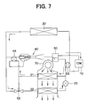
- FIG. 7 is a schematic diagram showing a refrigerant flow of the refrigerant cycle of the air conditioner in a dehumidifying - heating operation, according to the third embodiment; and
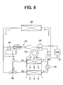
- FIG. 8 is a schematic diagram showing a refrigerant flow of the refrigerant cycle of the air conditioner in a heating operation, according to the third embodiment.
-
- Preferred embodiments of the present invention will be described hereinafter with reference to the accompanying drawings.
- A first preferred embodiment of the present invention will be now described with reference to FIGS. 1-3. In the first embodiment, the present invention can be typically applied to an air conditioner arranged for a compartment such as a house.
- A
compressor 10 shown in FIG. 1 is electrically driven to suck and compress refrigerant. In anexterior heat exchanger 20, refrigerant in an ejector cycle system (refrigerant cycle) is heat-exchanged with air (outside air) outside a compartment. A firstinterior heat exchanger 31 and a secondinterior heat exchanger 32 are disposed so that refrigerant in the ejector cycle system is heat-exchanged with air to be blown into a compartment. The firstinterior heat exchanger 31 and the secondinterior heat exchanger 32 are disposed in an air conditioning case defining an air passage through which air flows into the compartment. The firstinterior heat exchanger 31 is disposed at an upstream air side of the secondinterior heat exchanger 32 in the air conditioning case. In addition, the firstinterior heat exchanger 31 and the secondinterior heat exchanger 32 are disposed in series relative to a refrigerant flow. Adecompression valve 33, for decompressing refrigerant in a dehumidifying - heating operation, is provided in a refrigerant passage connecting the firstinterior heat exchanger 31 and the secondinterior heat exchanger 32. - An
ejector 40 decompresses and expands refrigerant at a high pressure side in the ejector cycle system so that gas refrigerant evaporated at a low pressure side is sucked therein, and converts an expansion energy to the pressure energy to increase a pressure of refrigerant to be sucked into thecompressor 10. - As shown in FIG. 2, the
ejector 40 includes anozzle 41, amixing portion 42 and adiffuser 43. The nozzle 410 decompresses and expands the refrigerant at the high pressure side by converting a pressure energy (pressure head) of the refrigerant to a speed energy (speed head) thereof. In themixing portion 42, the refrigerant evaporated at the low pressure side is sucked by high-speed refrigerant jetted from thenozzle 41. In thediffuser 43, the speed energy of refrigerant is converted to the pressure energy so that the pressure of refrigerant to be sucked into thecompressor 10 is increased, while the refrigerant jetted from thenozzle 41 and the refrigerant sucked into themixing portion 42 are mixed. - Here, the refrigerant pressure from the
ejector 40 is increased not only in thediffuser 43, but also in themixing portion 42 when the refrigerant, evaporated at the low pressure side, is sucked. Therefore, in theejector 40, a pressure-increasing portion is constructed by themixing portion 42 and thediffuser 43. In the first embodiment, a cross-sectional area of themixing portion 42 is made constant until thediffuser 43. However, themixing portion 42 may be tapered so that the cross-sectional area becomes larger toward thediffuser 43. Thenozzle 41 has athrottle portion 41a at which the passage sectional area is reduced in maximum. - As shown in FIG. 1, refrigerant from the
ejector 40 flows into a gas-liquid separator 50, to be separated into gas refrigerant and liquid refrigerant in the gas-liquid separator 50. In a cooling operation of the air conditioner, the gas refrigerant separated in the gas-liquid separator 50 is sucked into thecompressor 10, and the separated liquid refrigerant flows toward the first and secondinterior heat exchangers - Three-
way valves blower 70 is disposed to blow air into the compartment through the air conditioning case. In the first embodiment, the three-way valves compressor 10, thedecompression valve 33 and theblower 70 are controlled by en electronic control unit (ECU). - Next, operation of the air conditioner with the ejector cycle system will be now described.
- The general operation of the air conditioner is a cooling operation for cooling air to be blown into the compartment, or a dehumidifying - cooling operation for dehumidifying the compartment by cooling air to be blown into the compartment. In the cooling operation, the
decompression valve 33 is fully opened so that refrigerant is not decompressed in thedecompression valve 33. Further, thecompressor 10 and theblower 70 are operated, and the three-way valves condenser 20 flows into thenozzle 41 of theejector 40 and refrigerant from the first and secondinterior heat exchangers portion 42 of theejector 40. Accordingly, high-pressure refrigerant from thecompressor 10 is heat exchanged with outside air in thecondenser 20 to be cooled, and flows into thenozzle 41 of theejector 40 to be decompressed and expanded. Refrigerant from the first and secondinterior heat exchangers portion 42 of theejector 40 to be mixed with refrigerant from thenozzle 41. The dynamical pressure of the mixed refrigerant becomes the static pressure thereof, so that the pressure of the mixed refrigerant is increased in thediffuser 43. Refrigerant from theejector 40 flows into the gas-liquid separator 50. - On the other hand, because refrigerant in the first and second
interior heat exchangers ejector 40, liquid refrigerant in the gas-liquid separator 50 flows into the first and secondinterior heat exchangers interior heat exchangers liquid separator 50 is evaporated in the first and secondinterior heat exchangers interior heat exchangers interior heat exchangers compressor 10 and an air-blowing amount of theblower 70. - In the dehumidifying - heating operation, air to be blown into the compartment is cooled and dehumidified first in the first
interior heat exchanger 31, and the dehumidified air is heated in the secondinterior heat exchanger 32. Therefore, in the dehumidifying - heating operation, it can prevent the temperature of air blown into the compartment from being excessively reduced. - Specifically, the opening degree of the
decompression valve 33 for dehumidifying is reduced so that refrigerant is decompressed in thedecompression valve 33. On the other hand, the three-way valves ejector 40, while thecompressor 10 and theblower 70 are operated. Accordingly, refrigerant discharged from thecompressor 10 is cooled and condensed in theexterior heat exchanger 20 and the secondinterior heat exchanger 32, and is decompressed in thedecompression valve 33. Gas-liquid two-phase refrigerant decompressed in thedecompression valve 33 flows into the firstinterior heat exchanger 31. Liquid refrigerant flowing into the firstinterior heat exchanger 31 is evaporated by absorbing heat from air passing through the firstinterior heat exchanger 31. - In the dehumidifying - heating operation, air cooled and dehumidified in the first
interior heat exchanger 31 is heated in the secondinterior heat exchanger 32. Therefore, the compartment can be effectively dehumidified while it can prevent air to be blown into the compartment from being excessively cooled. Even in the dehumidifying - heating operation, the rotation speed of thecompressor 10, the opening degree of thedecompression valve 33 and the air blowing amount of theblower 70 are controlled by the electronic control unit, so that the temperature of air blown into the compartment can be suitably controlled. - A second preferred embodiment of the present invention will be now described with reference to FIGS. 4 and 5. In the above-described first embodiment, the first
interior heat exchanger 31 and the secondinterior heat exchanger 32 are disposed in series relative to the refrigerant flow. In the second embodiment, the firstinterior heat exchanger 31 and the secondinterior heat exchanger 32 are disposed in parallel relative to the refrigerant flow in the cooling operation, and thedecompression valve 33 is provided in a refrigerant passage connecting the first and secondinterior heat exchangers way valve 61 described in the first embodiment is omitted. - Next, the operation of the air conditioner with the ejector cycle system, according to the second embodiment, will be now described.
- In the cooling operation, as shown in FIG. 4, the
decompression valve 33 for dehumidifying is fully opened so that refrigerant is not decompressed in thedecompression valve 33. Further, the three-way valve 62 is operated, so that refrigerant from theexterior heat exchanger 20 flows into thenozzle 41 of theejector 40 while refrigerant from the first and secondinterior heat exchangers portion 42 of theejector 40. In the cooling operation, thecompressor 10 and theblower 70 are operated in this state. - Accordingly, gas refrigerant from the gas-
liquid separator 50 is sucked into thecompressor 10, and compressed refrigerant in thecompressor 10 is discharged to theexterior heat exchanger 20. Refrigerant cooled and condensed in theexterior heat exchanger 20 is decompressed and expanded in thenozzle 41 of theejector 40 so that gas refrigerant in the first and secondinterior heat exchangers ejector 40. Refrigerant sucked from the first and secondinterior heat exchangers nozzle 41 are mixed in the mixingportion 42, and the pressure of the mixed refrigerant is increased in thediffuser 43. Refrigerant from thediffuser 43 of theejector 40 flows into the gas-liquid separator 50. - On the other hand, because refrigerant in the first and second
interior heat exchangers ejector 40, liquid refrigerant in the gas-liquid separator 50 flows into the first and secondinterior heat exchangers interior heat exchangers liquid separator 50 is evaporated in the first and secondinterior heat exchangers interior heat exchangers compressor 10 and the air-blowing amount of theblower 70 are controlled so that the cooling capacity generated in the first and secondinterior heat exchangers - In the dehumidifying - heating operation, air to be blown into the compartment is cooled and dehumidified first, and the dehumidified air is heated. Specifically, the opening degree of the
decompression valve 33 for dehumidifying is reduced so that refrigerant is decompressed in thedecompression valve 33. On the other hand, the three-way valve 62 is operated so that a part of refrigerant from theexterior heat exchanger 20 flows into thenozzle 41 of theejector 40 and the other part of refrigerant from theexterior heat exchanger 20 flows into the secondinterior heat exchanger 32. In this state, thecompressor 10 and theblower 70 are operated. Accordingly, gas refrigerant from the gas-liquid separator 50 is sucked into thecompressor 10, and the compressed refrigerant is discharged from thecompressor 10 into theexterior heat exchanger 20. A part of refrigerant cooled and condensed in theexterior heat exchanger 20 is decompressed in thenozzle 41 of theejector 40 so that gas refrigerant in the firstinterior heat exchanger 31 is sucked into the mixingportion 42 of theejector 40. Refrigerant sucked from the firstinterior heat exchanger 31 and refrigerant jetted from thenozzle 41 are mixed in the mixingportion 42, and flows into the gas-liquid separator 50 after passing through thediffuser 43. Because refrigerant in the firstinterior heat exchanger 31 is sucked into theejector 40, liquid refrigerant in the gas-liquid separator 50 is supplied to the firstinterior heat exchanger 31, and is evaporated in the firstinterior heat exchanger 31 by absorbing heat from air passing through the firstinterior heat exchanger 31. - On the other hand, the other part of the refrigerant from the
exterior heat exchanger 20 flows into the secondinterior heat exchanger 32 before being decompressed. Refrigerant directly flowing into the secondinterior heat exchangers 32 from theexterior heat exchanger 20 has a relatively high temperature and high pressure. Therefore, air cooled and dehumidified in the firstinterior heat exchanger 31 is heated in the secondinterior heat exchanger 32. Accordingly, the compartment can be dehumidified while it can prevent air to be blown into the compartment from being excessively cooled. Refrigerant flowing from the secondinterior heat exchanger 32 is decompressed in thedecompression valve 33. Refrigerant decompressed in thedecompression valve 33 and liquid refrigerant flowing from the gas-liquid separator 50 are joined, and flows into the firstinterior heat exchanger 31. - In the dehumidifying - heating operation, the first
interior heat exchanger 31 functions as an evaporator of an ejector cycle similarly to the cooling operation, and the secondinterior heat exchanger 32 functions as a radiator (condenser) in an expansion cycle where thedecompression valve 33 is used as an expansion valve. - When the dehumidifying - heating operation is performed in an expansion valve cycle while refrigerant bypasses the
ejector 40 as in the first embodiment, consumed power in thecompressor 10 is increased in the dehumidifying - heating operation. However, in the second embodiment of the present invention, a part of high-pressure refrigerant from thecompressor 10 is introduced into theejector 40, while the other part of the high-pressure refrigerant, before being decompressed, is introduced into the secondinterior heat exchanger 32. The refrigerant flowing out of the secondinterior heat exchanger 32 is further introduced into the firstinterior heat exchanger 31 after being decompressed in thedecompression valve 33. Accordingly, even in dehumidifying - heating operation, consumed power in thecompressor 10 can be reduced. - In the above-described first embodiment, in the cooling operation, because both of liquid refrigerant and gas refrigerant evaporated in the first
interior heat exchanger 31 flows through thedecompression valve 33 and the secondinterior heat exchanger 32, the following problems may be caused in the cooling operation. For example, when the secondinterior heat exchanger 32 is a multi-type heat exchanger having plural tubes, it is difficult to flow refrigerant into the plural tubes uniformly because gas refrigerant density is greatly different from the liquid refrigerant density. On the other hand, when gas-liquid two-phase refrigerant flows into thedecompression valve 33, pressure loss generated in thedecompression valve 33 is increased as compared with a case where only liquid refrigerant flows through thedecompression valve 33. Therefore, it is need to increase the inner space of thedecompression valve 33 for removing this problem. However, in the second embodiment, in the cooling operation, only liquid refrigerant from the gas-liquid separator 50 is supplied to the firstinterior heat exchanger 31, and the secondinterior heat exchanger 32 through thedecompression valve 33 without being decompressed in thedecompression valve 33. Accordingly, in the second embodiment, the above-described problem is not caused in theory. - In the second embodiment of the present invention, in the dehumidifying - heating operation, refrigerant decompressed in the
decompression valve 33 flows into the firstinterior heat exchanger 31. Therefore, gas-liquid two-phase refrigerant may flow into the firstinterior heat exchanger 31 in the dehumidifying - heating operation. However, dehumidifying capacity necessary in the firstinterior heat exchanger 31 is small, a necessary heat-exchanging performance can be readily obtained in the first interior heat exchanger. - Accordingly, in the second embodiment, the compartment can be effectively dehumidified while it can prevent air to be blown into the compartment from being excessively cooled. Even in the dehumidifying - heating operation, the rotation speed of the
compressor 10, the opening degree of thedecompression valve 33 and the air blowing amount of theblower 70 are controlled by the electronic control unit, so that the temperature of air blown into the compartment can be controlled. - A third preferred embodiment of the present invention will be now described with reference to FIGS. 6-8. The third embodiment is a modification of the above-described second embodiment. In the third embodiment, similarly to the second embodiment, the first
interior heat exchanger 31 and the secondinterior heat exchanger 32 are arranged in parallel, relative to the refrigerant flow in the cooling operation. As shown in FIGS. 6-8, switchingvalves compressor 10 is switched to flow to theexterior heat exchanger 20 or to the first and secondinterior heat exchangers - FIG. 6 shows a refrigerant flow in the cooling operation of the third embodiment. In the cooling operation, the switching valves 62-64 are operated so that refrigerant flows similarly to that in the cooling operation of the second embodiment. FIG. 7 shows a refrigerant flow in the dehumidifying - heating operation of the third embodiment. In the dehumidifying - heating operation, the switching valves 62-64 are operated so that refrigerant flows similarly to that in the dehumidifying - heating operation of the second embodiment.
- FIG. 8 shows a refrigerant flow in the heating operation of the third embodiment. In the heating operation, the
decompression valve 33 for dehumidifying is fully opened. In the heating operation, gas refrigerant is sucked into thecompressor 10 from the gas-liquid separator 50 to be compressed in thecompressor 10. Gas refrigerant compressed in thecompressor 10 is discharged to the first and secondinterior heat exchangers interior heat exchangers interior heat exchangers nozzle 41 of theejector 40, while refrigerant in theexterior heat exchanger 20 is sucked into the mixingportion 42 of theejector 40. Refrigerant flowing into thenozzle 41 from the first and secondinterior heat exchangers ejector 40 from theexterior heat exchanger 20 are mixed in the mixingportion 42 of theejector 40, and the dynamic pressure of the refrigerant is changed to the static pressure thereof in thediffuser 43 of theejector 40. Thereafter, refrigerant from theejector 40 returns to the gas-liquid separator 50. - Because refrigerant in the
exterior heat exchanger 20 is sucked to theejector 40, liquid refrigerant in the gas-liquid separator 50 is supplied to theexterior heat exchanger 20, and is evaporated in theexterior heat exchanger 20 by absorbing heat from outside air. - Accordingly, in the third embodiment, the heating operation can be performed in addition to the cooling operation and the dehumidifying - heating operation. The heating operation described in the third embodiment can be performed in the above-described first embodiment.
- Although the present invention has been fully described in connection with the preferred embodiments thereof with reference to the accompanying drawings, it is to be noted that various changes and modifications will become apparent to those skilled in the art.
- For example, the air conditioner according to the present invention can be used for a vehicle or the other compartment. Further, in the above-described embodiments, a general refrigerant such as fluorocarbon (flon) is used. However, carbon dioxide or hydrocarbon can be also used as the refrigerant. In this case, the pressure of refrigerant at the high-pressure side becomes equal to or higher than the critical pressure of the refrigerant. Therefore, the effect of the ejector cycle system can be further improved.
- Such changes and modifications are to be understood as being within the scope of the present invention as defined by the appended claims.
Claims (11)
- An air conditioner for a compartment, comprising:a compressor (10) for sucking and compressing refrigerant;an exterior heat exchanger (20) for performing heat-exchange between the refrigerant and air outside the compartment;a first interior heat exchanger (31) for performing heat-exchange between the refrigerant and air to be blown into the compartment;a second interior heat exchanger (32) for performing heat-exchange between the refrigerant and air to be blown into the compartment, the second interior heat exchanger being disposed at a downstream air side of the first interior heat exchanger;an ejector (40) including a nozzle (41) for converting a pressure energy of high-pressure side refrigerant to a speed energy so that the high-pressure side refrigerant is decompressed and expanded, and a pressure-increasing portion in which the speed energy is converted to the pressure energy so that the pressure of refrigerant is increased while refrigerant discharged from the nozzle and gas refrigerant sucked from a low pressure side are mixed;a gas-liquid separator (50) for separating refrigerant into gas refrigerant and liquid refrigerant, the gas-liquid separator being coupled to the compressor such that gas refrigerant is sucked into the compressor; anda switching unit (61-64) for switching one of at least a cooling operation for cooling the compartment and a dehumidifying - heating operation for dehumidifying the compartment while restricting a temperature decrease in the compartment, wherein:in the cooling operation, refrigerant in the first and second interior heat exchangers is evaporated, and refrigerant in the exterior heat exchanger is radiated; andin the dehumidifying - heating operation, refrigerant is evaporated in the first interior heat exchanger while refrigerant in the second interior heat exchanger is radiated.
- The air conditioner according to claim 1, further comprising
a decompression unit (33) for decompressing refrigerant at least in the dehumidifying - heating operation, the decompression unit being disposed in a refrigerant passage connecting the first interior heat exchanger and the second interior heat exchanger. - The air conditioner according to claim 2, wherein:the first interior heat exchanger and the second interior heat exchanger are arranged in series, relative to a refrigerant flow.
- The air conditioner according to claim 3, wherein:in the cooling operation, refrigerant discharged from the compressor flows through the exterior heat exchanger, the nozzle of the ejector and the gas-liquid separator in this order, while liquid refrigerant in the gas-liquid separator flows through the first and second interior heat exchangers, the ejector and the gas-liquid separator in this order; andin the dehumidifying - heating operation, refrigerant discharged from the compressor flows through the exterior heat exchanger, the second interior heat exchanger, the decompression unit, the first interior heat exchanger and the gas-liquid separator in this order while bypassing the ejector.
- The air conditioner according to claim 2, wherein:the first interior heat exchanger and the second interior heat exchanger are arranged in parallel relative to a refrigerant flow, at least in the cooling operation; andat least in the dehumidifying - heating operation, a part of high-pressure refrigerant discharged from the compressor, before being decompressed, is introduced into the second interior heat exchanger, and flows into the first interior heat exchanger after being decompressed in the decompression unit, while the other part of the high-pressure refrigerant is introduced into the nozzle of the ejector.
- The air conditioner according to claim 1, wherein:the switching unit (61-64) is disposed to switch one of the cooling operation, the dehumidifying - heating operation, and a heating operation for heating the compartment; andin the heating operation, refrigerant is evaporated in the exterior heat exchanger while refrigerant is radiated in both the first and second interior heat exchangers.
- The air conditioner according to claim 6, wherein:in the heating operation, refrigerant discharged from the compressor flows through the first and second interior heat exchangers, the nozzle of the ejector and the gas-liquid separator, while liquid refrigerant in the gas-liquid separator flows through the exterior heat exchanger, the ejector and the gas-liquid separator in this order.
- The air conditioner according to claim 7, wherein the first interior heat exchanger and the second interior heat exchanger are arranged in parallel, relative to a refrigerant flow in the heating operation.
- The air conditioner according to claim 7, wherein the first interior heat exchanger and the second interior heat exchanger are arranged in series, relative to a refrigerant flow in the heating operation.
- The air conditioner according to claim 1, wherein:the switching unit is disposed to switch one of a first mode where refrigerant discharged from the compressor flows toward the exterior heat exchanger, and a second mode where refrigerant discharged from the compressor flows toward the first and second interior heat exchangers.
- The air conditioner according to any one of claims 1-10, wherein:one of carbon dioxide, fluorocarbon and hydrocarbon is used as the refrigerant.
Applications Claiming Priority (2)
| Application Number | Priority Date | Filing Date | Title |
|---|---|---|---|
| JP2002005844A JP4016659B2 (en) | 2002-01-15 | 2002-01-15 | Air conditioner |
| JP2002005844 | 2002-01-15 |
Publications (3)
| Publication Number | Publication Date |
|---|---|
| EP1327838A2 true EP1327838A2 (en) | 2003-07-16 |
| EP1327838A3 EP1327838A3 (en) | 2004-05-26 |
| EP1327838B1 EP1327838B1 (en) | 2008-09-03 |
Family
ID=19191155
Family Applications (1)
| Application Number | Title | Priority Date | Filing Date |
|---|---|---|---|
| EP03000555A Expired - Lifetime EP1327838B1 (en) | 2002-01-15 | 2003-01-10 | Air conditioner with ejector cycle system |
Country Status (7)
| Country | Link |
|---|---|
| US (1) | US6729157B2 (en) |
| EP (1) | EP1327838B1 (en) |
| JP (1) | JP4016659B2 (en) |
| KR (1) | KR100477305B1 (en) |
| CN (1) | CN1226582C (en) |
| CA (1) | CA2416208C (en) |
| DE (1) | DE60323280D1 (en) |
Cited By (9)
| Publication number | Priority date | Publication date | Assignee | Title |
|---|---|---|---|---|
| WO2006011789A1 (en) * | 2004-07-26 | 2006-02-02 | Antonie Bonte | Improvements in transcritical cooling systems |
| EP2050601A3 (en) * | 2007-10-16 | 2009-05-06 | Behr GmbH & Co. KG | Air conditioning device for a motor vehicle |
| EP2835589A3 (en) * | 2013-08-06 | 2015-03-04 | LG Electronics, Inc. | Air conditioner |
| EP2284457A4 (en) * | 2008-04-21 | 2017-04-19 | Daikin Industries, Ltd. | Heat exchanger unit |
| FR3051891A1 (en) * | 2016-05-27 | 2017-12-01 | Valeo Systemes Thermiques | AIR CONDITIONING SYSTEM, IN PARTICULAR FOR A MOTOR VEHICLE |
| NO344191B1 (en) * | 2018-06-25 | 2019-10-07 | Sinop Norge As | Apparatus and method for transferring heat |
| NO20181095A1 (en) * | 2018-08-20 | 2020-02-21 | Teknotherm Marine As Norway | Evaporator and refrigeration system with evaporator |
| EP4040073A4 (en) * | 2019-09-30 | 2023-04-19 | Daikin Industries, Ltd. | AIR CONDITIONER |
| CN118980196A (en) * | 2024-08-22 | 2024-11-19 | 青岛海尔空调器有限总公司 | Evaporator, air conditioning system, and dehumidification control method of air conditioning system |
Families Citing this family (54)
| Publication number | Priority date | Publication date | Assignee | Title |
|---|---|---|---|---|
| JP4200780B2 (en) * | 2003-02-14 | 2008-12-24 | 株式会社デンソー | Vapor compression refrigerator |
| JP4096824B2 (en) * | 2003-06-19 | 2008-06-04 | 株式会社デンソー | Vapor compression refrigerator |
| JP4001065B2 (en) * | 2003-06-30 | 2007-10-31 | 株式会社デンソー | Ejector cycle |
| US7254961B2 (en) * | 2004-02-18 | 2007-08-14 | Denso Corporation | Vapor compression cycle having ejector |
| US7191604B1 (en) * | 2004-02-26 | 2007-03-20 | Earth To Air Systems, Llc | Heat pump dehumidification system |
| US7591145B1 (en) * | 2004-02-26 | 2009-09-22 | Earth To Air Systems, Llc | Heat pump/direct expansion heat pump heating, cooling, and dehumidification system |
| CN100378411C (en) * | 2004-09-29 | 2008-04-02 | 株式会社电装 | Vapor compression refrigerant cycle system with ejector |
| JP4102799B2 (en) * | 2004-12-22 | 2008-06-18 | 日立アプライアンス株式会社 | Air conditioner |
| JP4626531B2 (en) * | 2005-04-01 | 2011-02-09 | 株式会社デンソー | Ejector refrigeration cycle |
| US20060254308A1 (en) * | 2005-05-16 | 2006-11-16 | Denso Corporation | Ejector cycle device |
| CN100507403C (en) * | 2005-05-24 | 2009-07-01 | 株式会社电装 | Injector and injection circulation device |
| DE102006062834B4 (en) * | 2005-06-30 | 2016-07-14 | Denso Corporation | ejector cycle |
| CN101487641B (en) * | 2005-06-30 | 2010-12-08 | 株式会社电装 | Ejector cycle system |
| JP4556791B2 (en) * | 2005-07-15 | 2010-10-06 | 株式会社デンソー | Ejector refrigeration cycle |
| CN100342186C (en) * | 2005-08-04 | 2007-10-10 | 上海交通大学 | Compression/injection mixed circulation refrigerating machine set |
| JP2007051833A (en) * | 2005-08-18 | 2007-03-01 | Denso Corp | Ejector refrigeration cycle |
| CN100416179C (en) * | 2007-03-08 | 2008-09-03 | 上海交通大学 | Refrigeration system with vortex ejector |
| JP4501984B2 (en) * | 2007-10-03 | 2010-07-14 | 株式会社デンソー | Ejector refrigeration cycle |
| JP4989420B2 (en) * | 2007-10-29 | 2012-08-01 | 日立アプライアンス株式会社 | Air conditioner |
| JP2009222357A (en) * | 2008-02-18 | 2009-10-01 | Daikin Ind Ltd | Refrigeration device |
| JP2009222359A (en) * | 2008-03-18 | 2009-10-01 | Daikin Ind Ltd | Refrigerating device |
| EP2314957B1 (en) * | 2009-05-14 | 2016-06-29 | Hanon Systems | Multi-evaporation system |
| DE102009039364A1 (en) * | 2009-08-29 | 2011-03-03 | Daimler Ag | Vehicle with at least one cooling circuit for cooling a fuel cell system |
| US8393171B2 (en) | 2010-04-13 | 2013-03-12 | Gerald Allen Alston | Mechanically enhanced ejector HVAC and electric power generation system |
| US20130111944A1 (en) * | 2010-07-23 | 2013-05-09 | Carrier Corporation | High Efficiency Ejector Cycle |
| CN103032119A (en) * | 2011-12-19 | 2013-04-10 | 摩尔动力(北京)技术股份有限公司 | Cold source power system |
| US10088241B1 (en) * | 2012-05-16 | 2018-10-02 | Engendren Corporation | Multi-mode heat exchange system for sensible and/or latent thermal management |
| US9127851B2 (en) * | 2012-06-28 | 2015-09-08 | Yixin Yang | Heating and cooling system including a heat pump and a heat storage tank |
| CN103712277B (en) * | 2012-09-29 | 2017-10-13 | 杭州三花研究院有限公司 | A kind of automotive air-conditioning system |
| JP5831423B2 (en) * | 2012-10-08 | 2015-12-09 | 株式会社デンソー | Refrigeration cycle equipment |
| CN104534725A (en) * | 2015-01-23 | 2015-04-22 | 珠海格力电器股份有限公司 | Air conditioner |
| RS56955B1 (en) * | 2015-04-22 | 2018-05-31 | Privredno Drustvo Za Pruzanje Usluga Iz Oblasti Automatike I Programiranja Synchrotek D O O | Hvac system of the vehicle passengers compartment with air flow topology change |
| US20170003040A1 (en) * | 2015-07-02 | 2017-01-05 | General Electric Company | Packaged terminal air conditioner unit |
| CN106322807B (en) | 2015-07-03 | 2021-05-28 | 开利公司 | Ejector heat pump |
| CN105910319B (en) * | 2016-05-27 | 2018-03-20 | 珠海格力电器股份有限公司 | Air conditioning system |
| CN106247508B (en) | 2016-09-12 | 2019-03-05 | 青岛海信日立空调系统有限公司 | Air conditioner heat pump system using ejector, air conditioner and air conditioner control method |
| FR3061454B1 (en) * | 2016-12-29 | 2019-07-05 | Liebherr-Aerospace Toulouse Sas | CONTROLLED TEMPERATURE AIR SUPPLY METHOD FOR A LAND VEHICLE CABIN AND A GROUND VEHICLE |
| US10350961B2 (en) * | 2017-02-23 | 2019-07-16 | Mahle International Gmbh | Multi-mode cabin heating system with dual heating source |
| US10254015B2 (en) * | 2017-02-28 | 2019-04-09 | Thermo King Corporation | Multi-zone transport refrigeration system with an ejector system |
| CN109572356B (en) * | 2018-10-18 | 2020-07-24 | 珠海格力电器股份有限公司 | Electric vehicle air conditioning system and electric vehicle with same |
| CN109515115B (en) * | 2018-11-27 | 2021-05-25 | 上海交通大学 | Automobile air conditioning system using carbon dioxide as working medium and control method |
| CN111912144A (en) * | 2019-05-07 | 2020-11-10 | 开利公司 | Heat exchange device |
| CN110165329B (en) * | 2019-05-28 | 2024-03-26 | 中国科学院理化技术研究所 | Power battery thermal management system |
| CN110986412B (en) * | 2019-11-25 | 2021-03-26 | 同济大学 | Air conditioner indoor unit with ejector and multi-split air conditioning system with indoor unit |
| EP3862657A1 (en) | 2020-02-10 | 2021-08-11 | Carrier Corporation | Refrigeration system with multiple heat absorbing heat exchangers |
| US12566016B2 (en) | 2020-11-11 | 2026-03-03 | Delta Development Team, Inc. | Autonomous portable refrigeration unit |
| CN112549903B (en) * | 2020-12-18 | 2025-01-21 | 武汉格罗夫氢能汽车有限公司 | Automobile air conditioning refrigeration system, test method and hydrogen-powered automobile |
| CN112833579B (en) * | 2021-01-22 | 2022-05-03 | 郑州大学 | Multi-mode heat pump tobacco curing system and control method thereof |
| CN113085481A (en) * | 2021-04-12 | 2021-07-09 | 北汽福田汽车股份有限公司 | Air conditioning system, control method of air conditioning system and vehicle |
| CN113310243B (en) * | 2021-05-21 | 2022-06-03 | 西安交通大学 | Mixed working medium low-temperature refrigeration circulation system adopting ejector and control method |
| CN113720034A (en) * | 2021-09-14 | 2021-11-30 | 珠海格力电器股份有限公司 | Air conditioner circulation system and control method of air conditioner |
| CN113701376A (en) * | 2021-09-14 | 2021-11-26 | 珠海格力电器股份有限公司 | Air conditioner circulation system and control method of air conditioner |
| CN113899095B (en) * | 2021-11-18 | 2022-06-21 | 山东大学 | A Quasi-Secondary Compression Circulation System with Ejector Synergy |
| CN115183490B (en) * | 2022-07-21 | 2025-06-24 | 珠海格力电器股份有限公司 | A refrigeration system |
Citations (1)
| Publication number | Priority date | Publication date | Assignee | Title |
|---|---|---|---|---|
| JPH05149652A (en) | 1991-11-27 | 1993-06-15 | Nippondenso Co Ltd | Pressure reducing device |
Family Cites Families (15)
| Publication number | Priority date | Publication date | Assignee | Title |
|---|---|---|---|---|
| US1871244A (en) * | 1931-08-19 | 1932-08-09 | Arthur B Steuart | Air conditioning system |
| US2195604A (en) * | 1937-03-27 | 1940-04-02 | Servel Inc | Refrigeration |
| NL147249B (en) * | 1964-12-19 | 1975-09-15 | Philips Nv | DEVICE FOR GENERATING COLD AND / OR LIQUEFIING GASES. |
| US3300995A (en) * | 1965-07-26 | 1967-01-31 | Carrier Corp | Reverse cycle refrigeration system |
| NL6607168A (en) * | 1966-05-25 | 1967-11-27 | ||
| US4218891A (en) * | 1978-05-22 | 1980-08-26 | Schwartzman Everett H | Cooling and heat pump systems and methods |
| US4321801A (en) * | 1981-01-26 | 1982-03-30 | Collard Jr Thomas H | Jet operated heat pump |
| US5343711A (en) * | 1993-01-04 | 1994-09-06 | Virginia Tech Intellectual Properties, Inc. | Method of reducing flow metastability in an ejector nozzle |
| JP3275410B2 (en) * | 1993-01-12 | 2002-04-15 | 松下電器産業株式会社 | Heat pump type air conditioner for vehicles |
| US5444987A (en) * | 1993-07-02 | 1995-08-29 | Alsenz; Richard H. | Refrigeration system utilizing a jet enthalpy compressor for elevating the suction line pressure |
| US5553457A (en) * | 1994-09-29 | 1996-09-10 | Reznikov; Lev | Cooling device |
| JP3246250B2 (en) * | 1995-02-16 | 2002-01-15 | 松下電器産業株式会社 | Heat pump air conditioner dehumidifier for electric vehicles |
| JP3436872B2 (en) * | 1997-11-07 | 2003-08-18 | 株式会社テージーケー | Automotive air conditioners |
| FI108197B (en) * | 1998-09-11 | 2001-11-30 | Nokia Mobile Phones Ltd | Procedure and arrangement for processing subscriber information in a mobile telephony |
| JP4639541B2 (en) * | 2001-03-01 | 2011-02-23 | 株式会社デンソー | Cycle using ejector |
-
2002
- 2002-01-15 JP JP2002005844A patent/JP4016659B2/en not_active Expired - Fee Related
- 2002-12-31 US US10/335,371 patent/US6729157B2/en not_active Expired - Lifetime
-
2003
- 2003-01-08 CN CNB031010288A patent/CN1226582C/en not_active Expired - Fee Related
- 2003-01-10 EP EP03000555A patent/EP1327838B1/en not_active Expired - Lifetime
- 2003-01-10 DE DE60323280T patent/DE60323280D1/en not_active Expired - Lifetime
- 2003-01-13 CA CA002416208A patent/CA2416208C/en not_active Expired - Fee Related
- 2003-01-14 KR KR10-2003-0002441A patent/KR100477305B1/en not_active Expired - Fee Related
Patent Citations (1)
| Publication number | Priority date | Publication date | Assignee | Title |
|---|---|---|---|---|
| JPH05149652A (en) | 1991-11-27 | 1993-06-15 | Nippondenso Co Ltd | Pressure reducing device |
Cited By (15)
| Publication number | Priority date | Publication date | Assignee | Title |
|---|---|---|---|---|
| WO2006011789A1 (en) * | 2004-07-26 | 2006-02-02 | Antonie Bonte | Improvements in transcritical cooling systems |
| EP2050601A3 (en) * | 2007-10-16 | 2009-05-06 | Behr GmbH & Co. KG | Air conditioning device for a motor vehicle |
| EP2230113A1 (en) * | 2007-10-16 | 2010-09-22 | Behr GmbH & Co. KG | Air conditioning device for a motor vehicle |
| EP2284457A4 (en) * | 2008-04-21 | 2017-04-19 | Daikin Industries, Ltd. | Heat exchanger unit |
| EP2835589A3 (en) * | 2013-08-06 | 2015-03-04 | LG Electronics, Inc. | Air conditioner |
| FR3051891A1 (en) * | 2016-05-27 | 2017-12-01 | Valeo Systemes Thermiques | AIR CONDITIONING SYSTEM, IN PARTICULAR FOR A MOTOR VEHICLE |
| NO344191B1 (en) * | 2018-06-25 | 2019-10-07 | Sinop Norge As | Apparatus and method for transferring heat |
| WO2020005071A1 (en) * | 2018-06-25 | 2020-01-02 | Sinop Norge As | Apparatus and method for transferring heat |
| AU2019292493B2 (en) * | 2018-06-25 | 2021-10-28 | Sinop Norge As | Apparatus and method for transferring heat |
| EP3811004A4 (en) * | 2018-06-25 | 2022-03-23 | Technoblock Sinop AS | Apparatus and method for transferring heat |
| NO20181095A1 (en) * | 2018-08-20 | 2020-02-21 | Teknotherm Marine As Norway | Evaporator and refrigeration system with evaporator |
| NO345004B1 (en) * | 2018-08-20 | 2020-08-17 | Teknotherm Marine As Norway | Evaporator and refrigeration system with evaporator |
| EP4040073A4 (en) * | 2019-09-30 | 2023-04-19 | Daikin Industries, Ltd. | AIR CONDITIONER |
| US12442549B2 (en) | 2019-09-30 | 2025-10-14 | Daikin Industries, Ltd. | Air conditioner |
| CN118980196A (en) * | 2024-08-22 | 2024-11-19 | 青岛海尔空调器有限总公司 | Evaporator, air conditioning system, and dehumidification control method of air conditioning system |
Also Published As
| Publication number | Publication date |
|---|---|
| EP1327838B1 (en) | 2008-09-03 |
| US6729157B2 (en) | 2004-05-04 |
| DE60323280D1 (en) | 2008-10-16 |
| KR20030061684A (en) | 2003-07-22 |
| CN1226582C (en) | 2005-11-09 |
| CA2416208C (en) | 2005-10-18 |
| JP2003207218A (en) | 2003-07-25 |
| CN1432775A (en) | 2003-07-30 |
| CA2416208A1 (en) | 2003-07-15 |
| EP1327838A3 (en) | 2004-05-26 |
| US20030131611A1 (en) | 2003-07-17 |
| KR100477305B1 (en) | 2005-03-18 |
| JP4016659B2 (en) | 2007-12-05 |
Similar Documents
| Publication | Publication Date | Title |
|---|---|---|
| US6729157B2 (en) | Air conditioner with ejector cycle system | |
| EP2348266B1 (en) | Ejector cycle system | |
| KR100525153B1 (en) | Ejector cycle system | |
| AU2002301307B2 (en) | Ejector cycle system | |
| US6868679B2 (en) | Ejector cycle system | |
| US6966199B2 (en) | Ejector with throttle controllable nozzle and ejector cycle using the same | |
| US6857286B2 (en) | Vapor-compression refrigerant cycle system | |
| US8104308B2 (en) | Refrigerant cycle device with ejector | |
| US6945074B2 (en) | Vapor-compression refrigerant cycle system | |
| JP4989420B2 (en) | Air conditioner | |
| JP7135583B2 (en) | refrigeration cycle equipment | |
| US6807819B2 (en) | Vapor compression refrigerant cycle |
Legal Events
| Date | Code | Title | Description |
|---|---|---|---|
| PUAI | Public reference made under article 153(3) epc to a published international application that has entered the european phase |
Free format text: ORIGINAL CODE: 0009012 |
|
| AK | Designated contracting states |
Designated state(s): AT BE BG CH CY CZ DE DK EE ES FI FR GB GR HU IE IT LI LU MC NL PT SE SI SK TR |
|
| AX | Request for extension of the european patent |
Extension state: AL LT LV MK RO |
|
| PUAL | Search report despatched |
Free format text: ORIGINAL CODE: 0009013 |
|
| AK | Designated contracting states |
Kind code of ref document: A3 Designated state(s): AT BE BG CH CY CZ DE DK EE ES FI FR GB GR HU IE IT LI LU MC NL PT SE SI SK TR |
|
| AX | Request for extension of the european patent |
Extension state: AL LT LV MK RO |
|
| RIC1 | Information provided on ipc code assigned before grant |
Ipc: 7F 25B 5/04 B Ipc: 7F 25B 41/00 A Ipc: 7F 25B 5/02 B |
|
| 17P | Request for examination filed |
Effective date: 20040615 |
|
| AKX | Designation fees paid |
Designated state(s): DE FR GB |
|
| 17Q | First examination report despatched |
Effective date: 20060811 |
|
| 17Q | First examination report despatched |
Effective date: 20060811 |
|
| GRAP | Despatch of communication of intention to grant a patent |
Free format text: ORIGINAL CODE: EPIDOSNIGR1 |
|
| GRAS | Grant fee paid |
Free format text: ORIGINAL CODE: EPIDOSNIGR3 |
|
| GRAA | (expected) grant |
Free format text: ORIGINAL CODE: 0009210 |
|
| AK | Designated contracting states |
Kind code of ref document: B1 Designated state(s): DE FR GB |
|
| REG | Reference to a national code |
Ref country code: GB Ref legal event code: FG4D |
|
| REF | Corresponds to: |
Ref document number: 60323280 Country of ref document: DE Date of ref document: 20081016 Kind code of ref document: P |
|
| PLBE | No opposition filed within time limit |
Free format text: ORIGINAL CODE: 0009261 |
|
| STAA | Information on the status of an ep patent application or granted ep patent |
Free format text: STATUS: NO OPPOSITION FILED WITHIN TIME LIMIT |
|
| 26N | No opposition filed |
Effective date: 20090604 |
|
| PGFP | Annual fee paid to national office [announced via postgrant information from national office to epo] |
Ref country code: FR Payment date: 20100208 Year of fee payment: 8 |
|
| PGFP | Annual fee paid to national office [announced via postgrant information from national office to epo] |
Ref country code: GB Payment date: 20100106 Year of fee payment: 8 |
|
| GBPC | Gb: european patent ceased through non-payment of renewal fee |
Effective date: 20110110 |
|
| REG | Reference to a national code |
Ref country code: FR Ref legal event code: ST Effective date: 20110930 |
|
| PG25 | Lapsed in a contracting state [announced via postgrant information from national office to epo] |
Ref country code: FR Free format text: LAPSE BECAUSE OF NON-PAYMENT OF DUE FEES Effective date: 20110131 |
|
| PG25 | Lapsed in a contracting state [announced via postgrant information from national office to epo] |
Ref country code: GB Free format text: LAPSE BECAUSE OF NON-PAYMENT OF DUE FEES Effective date: 20110110 |
|
| PGFP | Annual fee paid to national office [announced via postgrant information from national office to epo] |
Ref country code: DE Payment date: 20180122 Year of fee payment: 16 |
|
| REG | Reference to a national code |
Ref country code: DE Ref legal event code: R119 Ref document number: 60323280 Country of ref document: DE |
|
| PG25 | Lapsed in a contracting state [announced via postgrant information from national office to epo] |
Ref country code: DE Free format text: LAPSE BECAUSE OF NON-PAYMENT OF DUE FEES Effective date: 20190801 |