EP1327788B1 - Ensemble comportant des éléments de roulement - Google Patents
Ensemble comportant des éléments de roulement Download PDFInfo
- Publication number
- EP1327788B1 EP1327788B1 EP02292891A EP02292891A EP1327788B1 EP 1327788 B1 EP1327788 B1 EP 1327788B1 EP 02292891 A EP02292891 A EP 02292891A EP 02292891 A EP02292891 A EP 02292891A EP 1327788 B1 EP1327788 B1 EP 1327788B1
- Authority
- EP
- European Patent Office
- Prior art keywords
- assembly according
- cage
- shaft
- rolling elements
- assembly
- Prior art date
- Legal status (The legal status is an assumption and is not a legal conclusion. Google has not performed a legal analysis and makes no representation as to the accuracy of the status listed.)
- Expired - Lifetime
Links
- 238000005096 rolling process Methods 0.000 title claims description 28
- 238000007789 sealing Methods 0.000 claims description 29
- 239000000314 lubricant Substances 0.000 claims description 26
- 238000004891 communication Methods 0.000 claims description 17
- 238000011084 recovery Methods 0.000 claims description 6
- 238000005507 spraying Methods 0.000 claims description 3
- 238000005266 casting Methods 0.000 claims 1
- 238000005119 centrifugation Methods 0.000 description 1
- 239000000470 constituent Substances 0.000 description 1
- 238000001816 cooling Methods 0.000 description 1
- 239000007921 spray Substances 0.000 description 1
- 238000004804 winding Methods 0.000 description 1
Images


Classifications
-
- F—MECHANICAL ENGINEERING; LIGHTING; HEATING; WEAPONS; BLASTING
- F16—ENGINEERING ELEMENTS AND UNITS; GENERAL MEASURES FOR PRODUCING AND MAINTAINING EFFECTIVE FUNCTIONING OF MACHINES OR INSTALLATIONS; THERMAL INSULATION IN GENERAL
- F16C—SHAFTS; FLEXIBLE SHAFTS; ELEMENTS OR CRANKSHAFT MECHANISMS; ROTARY BODIES OTHER THAN GEARING ELEMENTS; BEARINGS
- F16C33/00—Parts of bearings; Special methods for making bearings or parts thereof
- F16C33/30—Parts of ball or roller bearings
- F16C33/66—Special parts or details in view of lubrication
- F16C33/6637—Special parts or details in view of lubrication with liquid lubricant
- F16C33/6685—Details of collecting or draining, e.g. returning the liquid to a sump
-
- F—MECHANICAL ENGINEERING; LIGHTING; HEATING; WEAPONS; BLASTING
- F16—ENGINEERING ELEMENTS AND UNITS; GENERAL MEASURES FOR PRODUCING AND MAINTAINING EFFECTIVE FUNCTIONING OF MACHINES OR INSTALLATIONS; THERMAL INSULATION IN GENERAL
- F16C—SHAFTS; FLEXIBLE SHAFTS; ELEMENTS OR CRANKSHAFT MECHANISMS; ROTARY BODIES OTHER THAN GEARING ELEMENTS; BEARINGS
- F16C33/00—Parts of bearings; Special methods for making bearings or parts thereof
- F16C33/72—Sealings
- F16C33/76—Sealings of ball or roller bearings
- F16C33/762—Sealings of ball or roller bearings by means of a fluid
-
- F—MECHANICAL ENGINEERING; LIGHTING; HEATING; WEAPONS; BLASTING
- F16—ENGINEERING ELEMENTS AND UNITS; GENERAL MEASURES FOR PRODUCING AND MAINTAINING EFFECTIVE FUNCTIONING OF MACHINES OR INSTALLATIONS; THERMAL INSULATION IN GENERAL
- F16C—SHAFTS; FLEXIBLE SHAFTS; ELEMENTS OR CRANKSHAFT MECHANISMS; ROTARY BODIES OTHER THAN GEARING ELEMENTS; BEARINGS
- F16C33/00—Parts of bearings; Special methods for making bearings or parts thereof
- F16C33/72—Sealings
- F16C33/76—Sealings of ball or roller bearings
- F16C33/78—Sealings of ball or roller bearings with a diaphragm, disc, or ring, with or without resilient members
- F16C33/7886—Sealings of ball or roller bearings with a diaphragm, disc, or ring, with or without resilient members mounted outside the gap between the inner and outer races, e.g. sealing rings mounted to an end face or outer surface of a race
-
- F—MECHANICAL ENGINEERING; LIGHTING; HEATING; WEAPONS; BLASTING
- F16—ENGINEERING ELEMENTS AND UNITS; GENERAL MEASURES FOR PRODUCING AND MAINTAINING EFFECTIVE FUNCTIONING OF MACHINES OR INSTALLATIONS; THERMAL INSULATION IN GENERAL
- F16C—SHAFTS; FLEXIBLE SHAFTS; ELEMENTS OR CRANKSHAFT MECHANISMS; ROTARY BODIES OTHER THAN GEARING ELEMENTS; BEARINGS
- F16C35/00—Rigid support of bearing units; Housings, e.g. caps, covers
- F16C35/04—Rigid support of bearing units; Housings, e.g. caps, covers in the case of ball or roller bearings
- F16C35/042—Housings for rolling element bearings for rotary movement
-
- F—MECHANICAL ENGINEERING; LIGHTING; HEATING; WEAPONS; BLASTING
- F16—ENGINEERING ELEMENTS AND UNITS; GENERAL MEASURES FOR PRODUCING AND MAINTAINING EFFECTIVE FUNCTIONING OF MACHINES OR INSTALLATIONS; THERMAL INSULATION IN GENERAL
- F16J—PISTONS; CYLINDERS; SEALINGS
- F16J15/00—Sealings
- F16J15/002—Sealings comprising at least two sealings in succession
- F16J15/004—Sealings comprising at least two sealings in succession forming of recuperation chamber for the leaking fluid
-
- F—MECHANICAL ENGINEERING; LIGHTING; HEATING; WEAPONS; BLASTING
- F16—ENGINEERING ELEMENTS AND UNITS; GENERAL MEASURES FOR PRODUCING AND MAINTAINING EFFECTIVE FUNCTIONING OF MACHINES OR INSTALLATIONS; THERMAL INSULATION IN GENERAL
- F16J—PISTONS; CYLINDERS; SEALINGS
- F16J15/00—Sealings
- F16J15/16—Sealings between relatively-moving surfaces
- F16J15/164—Sealings between relatively-moving surfaces the sealing action depending on movements; pressure difference, temperature or presence of leaking fluid
-
- F—MECHANICAL ENGINEERING; LIGHTING; HEATING; WEAPONS; BLASTING
- F16—ENGINEERING ELEMENTS AND UNITS; GENERAL MEASURES FOR PRODUCING AND MAINTAINING EFFECTIVE FUNCTIONING OF MACHINES OR INSTALLATIONS; THERMAL INSULATION IN GENERAL
- F16J—PISTONS; CYLINDERS; SEALINGS
- F16J15/00—Sealings
- F16J15/16—Sealings between relatively-moving surfaces
- F16J15/40—Sealings between relatively-moving surfaces by means of fluid
-
- F—MECHANICAL ENGINEERING; LIGHTING; HEATING; WEAPONS; BLASTING
- F16—ENGINEERING ELEMENTS AND UNITS; GENERAL MEASURES FOR PRODUCING AND MAINTAINING EFFECTIVE FUNCTIONING OF MACHINES OR INSTALLATIONS; THERMAL INSULATION IN GENERAL
- F16C—SHAFTS; FLEXIBLE SHAFTS; ELEMENTS OR CRANKSHAFT MECHANISMS; ROTARY BODIES OTHER THAN GEARING ELEMENTS; BEARINGS
- F16C19/00—Bearings with rolling contact, for exclusively rotary movement
- F16C19/02—Bearings with rolling contact, for exclusively rotary movement with bearing balls essentially of the same size in one or more circular rows
- F16C19/04—Bearings with rolling contact, for exclusively rotary movement with bearing balls essentially of the same size in one or more circular rows for radial load mainly
- F16C19/06—Bearings with rolling contact, for exclusively rotary movement with bearing balls essentially of the same size in one or more circular rows for radial load mainly with a single row or balls
-
- F—MECHANICAL ENGINEERING; LIGHTING; HEATING; WEAPONS; BLASTING
- F16—ENGINEERING ELEMENTS AND UNITS; GENERAL MEASURES FOR PRODUCING AND MAINTAINING EFFECTIVE FUNCTIONING OF MACHINES OR INSTALLATIONS; THERMAL INSULATION IN GENERAL
- F16C—SHAFTS; FLEXIBLE SHAFTS; ELEMENTS OR CRANKSHAFT MECHANISMS; ROTARY BODIES OTHER THAN GEARING ELEMENTS; BEARINGS
- F16C2380/00—Electrical apparatus
- F16C2380/26—Dynamo-electric machines or combinations therewith, e.g. electro-motors and generators
Definitions
- the present invention relates to the field of bearings and more particularly to an assembly comprising a cage and rolling elements placed inside the cage, these rolling elements being intended to support a shaft passing through the cage, the latter comprising parts of sealing on both sides of the rolling elements.
- the sealing portions may comprise, in a conventional manner, reliefs such as grooves, for retaining a lubricant inside the cage, especially when the shaft rotates at a high speed and that joints applying on the tree are not usable.
- the invention aims to improve the reliability of the rolling elements, in particular by reducing the risk of leakage of lubricant at the sealing parts, especially when the air pressures outside the cage on the part and else of the latter are not the same, which may be the case for example when the cage is mounted on the end flange of a rotating electrical machine and that it comprises a fan rotating at the inside the carcass of the machine.
- Requirement AU 438891 discloses an assembly comprising a cage and rolling elements placed inside the cage, the rolling elements being intended to support a shaft passing through said cage, the latter comprising sealing portions on either side of said elements of rolling, this assembly comprising at least one communication between two spaces formed between said sealing portions and the shaft.
- the aforementioned communication reduces the risk that lubricant is driven by a current of air flowing between the shaft and at least one of the sealing portions.
- the spaces formed between the sealing portions and the shaft may be for example defined by annular grooves of the sealing portions.
- the sealing portions are preferably without contact with the shaft.
- the sealing portions may include reliefs such as grooves.
- the assembly may comprise for example reliefs such as grooves on either side of each of said spaces, for retaining the lubricant in the cage.
- the grooves are helical.
- the aforementioned communication may for example comprise channels made inside walls of the cage.
- the cage may for example comprise at least two half-shells, also called cage bottoms, disposed respectively on either side of the rolling elements.
- Each half-shell may for example be made in one piece with a sealing portion, for example by foundry.
- the aforementioned communication may comprise at least one inner channel made in at least one half-shells.
- the cage comprises an intermediate piece between the two half-shells.
- This intermediate piece can serve as support for a ring in contact with which the rolling elements roll.
- the communication may comprise at least one channel made in the intermediate piece, for example four channels.
- the intermediate piece may further comprise at least one channel allowing a lubricant flow between two regions of the cage located on either side of the rolling elements.
- This channel may extend for example along an inclined axis forming a non-zero angle relative to the axis of the shaft, to allow the flow of sprayed lubricant in the cage to a drain hole.
- the intermediate piece may for example be arranged to attach to the end flanges of an electric machine casing.
- At least one of the sealing portions may comprise a lubricant recovery groove, this groove being disposed between grooves opening on the shaft, and communicating via at least one channel with the interior of the cage.
- the rolling elements may comprise balls.
- the assembly may comprise two rings between which the rolling elements roll, one of the rings being in contact with the shaft, and the other ring being in contact with the cage, for example in contact. of the aforementioned intermediate piece when it exists.
- the assembly is adapted to receive a spraying member adapted to spray lubricant inside the cage.
- the diameter of the shaft at the bearings can for example be greater than or equal to 50 mm, and in particular greater than or equal to 100 mm.
- the cage has a low point with a lubricant drain hole.
- the cage may be, in operation, at least partially filled with a lubricant which is for example oil.
- the invention also relates to a rotating machine which comprises at least one assembly as described above.
- This machine may comprise for example a fan inside the carcass of the machine, which fan may for example be rotated by the shaft.
- the machine may comprise at least one conduit opening on the one hand in said at least one communication and on the other hand inside the carcass of the machine, at the outlet of the fan.
- the stator 2 comprises a carcass 4 inside which is disposed a magnetic circuit 5 comprising a stack of magnetic sheets and having windings 6, in a conventional manner.
- the carcass 4 comprises end flanges 7 and 8 each supporting an assembly 10 containing rolling elements.
- the two sets 10 have been represented only partially and very schematically on the figure 1 , for the sake of clarity of the drawing.
- the two sets 10 are arranged symmetrically with each other with respect to a median plane perpendicular to the X axis.
- the rotor 3 comprises a shaft 12 which carries a magnetic circuit 13 comprising a stack of magnetic sheets and a fan 14 for generating a cooling air stream inside the machine.
- Each assembly 10 comprises rolling elements 20, constituted in the embodiment described by balls, rotating between two rings 21 and 22, the ring 21, radially innermost, being in contact with the shaft 12, and the ring 22, radially outermost, being in contact with an intermediate piece 23 disposed between an inner half-shell 24 and an outer half-shell 25, the half-shells 24 and 25 and the intermediate piece 23 constituting a cage housing the rolling elements 20.
- a lubricant is sprayed continuously, during operation of the machine, inside the cage by at least one spraying member, not shown.
- the lubricant used is, for example, oil.
- the oil sprayed inside the cage can be collected at a low point thereof by a drain hole 27, which can be seen on the figure 8 .
- the half-shells 24 and 25 have respective annular sealing portions 30 and 31.
- Each sealing portion 30 or 31 extends without contact with the shaft and comprises reliefs 40 intended to oppose a departure of lubricant by the existing set between the sealing parts and the shaft.
- these reliefs 40 comprise helical grooves.
- the sealing portion of the outer half-shell 25 may thus comprise for example a helical groove 31a, 31b constituted by a triangular thread ISO thread having a pitch of 5 mm to the left.
- a lubricant recovery groove 41 is formed on the threaded portion 31a and communicates with the inside of the cage via a channel 42, as can be seen in FIG. figure 6 .
- the sealing portion 30 of the inner half-shell 24 also has a threaded portion 30a, 30b and a similar recovery groove 43 communicating via a channel 44 with the interior of the cage, as can be seen in FIG. figure 4 .
- the shaft comprises, facing each groove 41 or 43 of lubricant recovery, an annular ridge 120 located at the bottom of a groove 121, the ridge 120 for projecting the lubricant present on the shaft, by centrifugation, in the recovery throat.
- the orientation of the threads is chosen, given the direction of rotation of the machine, so that the grooves tend to bring the lubricant back into the cage.
- An annular groove 50 is formed in the sealing portion 31 and opens onto the shaft 12. This groove 50 communicates with channels 51, four in number in the illustrated example, each of these channels 51 opening through an orifice 52 on the edge of the outer half-shell 25, as can be seen on the figure 5 .
- the inner half-shell 24 similarly comprises a groove 60 communicating via channels 61, four in number in the illustrated example, with corresponding orifices 62, opening on its edge.
- the orifices 52 are arranged symmetrically with respect to a vertical median plane, as can be seen in FIG. figure 3 . It is the same with orifices 62.
- the sealing portions 30 and 31 have respective regions 30b and 31b, extending a short distance from the shaft and provided with reliefs such as for example helical grooves, these regions 30b and 31b extending between the grooves 60 and 50 and the end of the half-shell opposite the other half-shell.
- the channels 51 and 61 communicate with each other via channels 70 made in the intermediate part 23, four in number in the illustrated example. channels having ends opening opposite the orifices 52 and 62, as can be seen on the figure 7 .
- the intermediate part 23 also comprises at least one channel 72 making it possible to establish a communication between two regions 73 and 74 of the cage located on either side of the rolling elements 20, as can be seen on the figure 8 .
- This channel 72 allows the lubricant to flow to the drain port 27.
- the channels 51, 61 and 70 make it possible to establish a communication between the grooves 50 and 60, which makes it possible to reduce the risks of leakage of lubricant during operation of the machine 1.
- the fan 14 creates a vacuum outside the adjacent assembly 10, on the side of the inner half-shell 24.
- conduit 80 opening on the one hand to the outlet 81 of the fan 14 inside the carcass, and secondly in the channel 51 of the outer half-shell 25 of the assembly 10 located on the fan 14 side .
- This duct 80 makes it possible to bring air from the fan 14 into the grooves 50 and 60 on either side of the bearing, and to push back towards the bearing the oil which tends to flow towards the depression created by the fan 14 outside the assembly 10.
- the presence of the duct 80 is all the more advantageous when the machine operates with an inclination tending to run the lubricant towards the fan 14, or if there are relatively large differences in pressure between the outside and the outside. the inside of the machine on the side of the fan 14, especially if the speed of rotation thereof is high.
- the balls 20 may be replaced by other rolling elements such as for example needles, cylindrical or conical rollers.
- the rolling elements can take purely radial or radial and axial forces.
- the invention can be applied to machines other than rotating electrical machines, especially thermal machines.
- shapes can be given to half-shells different from those illustrated and in particular, it is possible to produce an assembly according to the invention with only two half-shells assembled one against the other. other, without intermediate piece.
- the inner channels of the cage may be replaced by channels formed by means of inserts.
- the channels may have various sections, circular or otherwise.
- the profile of the grooves may be triangular or other, in particular rectangular or trapezoidal.
Landscapes
- Engineering & Computer Science (AREA)
- General Engineering & Computer Science (AREA)
- Mechanical Engineering (AREA)
- Rolling Contact Bearings (AREA)
- Sealing Of Bearings (AREA)
Description
- La présente invention concerne le domaine des roulements et plus particulièrement un ensemble comportant une cage et des éléments de roulement placés à l'intérieur de la cage, ces éléments de roulement étant destinés à supporter un arbre traversant la cage, cette dernière comportant des parties d'étanchéité de part et d'autre des éléments de roulement.
- Les parties d'étanchéité peuvent comporter, de manière conventionnelle, des reliefs tels que des rainures, permettant de retenir un lubrifiant à l'intérieur de la cage, notamment lorsque l'arbre tourne à une vitesse élevée et que des joints s'appliquant sur l'arbre ne sont pas utilisables.
- L'invention vise à améliorer la fiabilité des éléments de roulement, en permettant notamment de réduire les risques de fuite de lubrifiant au niveau des parties d'étanchéité, notamment lorsque les pressions de l'air à l'extérieur de la cage de part et d'autre de celle-ci ne sont pas les mêmes, ce qui peut être le cas par exemple lorsque la cage est montée sur le flasque d'extrémité d'une machine électrique tournante et que celle-ci comporte un ventilateur tournant à l'intérieur de la carcasse de la machine.
- La demande
AU 438891 - La communication précitée permet de réduire le risque que du lubrifiant ne soit entraîné par un courant d'air qui circulerait entre l'arbre et l'une au moins des parties d'étanchéité.
- Les espaces formés entre les parties d'étanchéité et l'arbre peuvent être par exemple définis par des gorges annulaires des parties d'étanchéité.
- Les parties d'étanchéité sont de préférence sans contact avec l'arbre.
- Les parties d'étanchéité peuvent comporter des reliefs tels que des rainures. L'ensemble peut comporter par exemple des reliefs tels que des rainures de part et d'autre de chacun desdits espaces, pour retenir le lubrifiant dans la cage.
- Selon la revendication 1, les rainures sont hélicoïdales.
- La communication précitée peut par exemple comporter des canaux réalisés à l'intérieur de parois de la cage.
- La cage peut par exemple comporter au moins deux demi-coques, encore appelées fonds de cage, disposées respectivement de part et d'autre des éléments de roulement.
- Chaque demi-coque peut par exemple être réalisée d'un seul tenant avec une partie d'étanchéité, par exemple par fonderie.
- La communication précitée peut comporter au moins un canal intérieur réalisé dans l'une au moins des demi-coques.
- Dans une mise en oeuvre particulière de l'invention, la cage comporte une pièce intermédiaire entre les deux demi-coques. Cette pièce intermédiaire peut servir de support à une bague au contact de laquelle roulent les éléments de roulement.
- La communication peut comporter au moins un canal réalisé dans la pièce intermédiaire, par exemple quatre canaux.
- La pièce intermédiaire peut en outre comporter au moins un canal permettant une circulation de lubrifiant entre deux régions de la cage situées de part et d'autre des éléments de roulements. Ce canal peut s'étendre par exemple selon un axe incliné faisant un angle non nul par rapport à l'axe de l'arbre, pour permettre l'écoulement de lubrifiant pulvérisé dans la cage vers un orifice de vidange.
- La pièce intermédiaire peut par exemple être agencée pour se fixer sur des flasques d'extrémité d'une carcasse de machine électrique.
- Au moins l'une des parties d'étanchéité peut comporter une gorge de récupération du lubrifiant, cette gorge étant disposée entre des rainures débouchant sur l'arbre, et communicant par au moins un canal avec l'intérieur de la cage.
- Dans une mise en oeuvre de l'invention, les éléments de roulement peuvent comporter des billes. Dans l'exemple décrit, l'ensemble peut comporter deux bagues entre lesquelles les éléments de roulement roulent, l'une des bagues étant au contact de l'arbre, et l'autre bague étant au contact de la cage, par exemple au contact de la pièce intermédiaire précitée lorsque celle-ci existe.
- Dans une mise en oeuvre de l'invention, l'ensemble est adapté à recevoir un organe de pulvérisation apte à pulvériser du lubrifiant à l'intérieur de la cage.
- Le diamètre de l'arbre au niveau des roulements peut par exemple être supérieur ou égal à 50 mm, et notamment supérieur ou égal à 100 mm.
- Dans une mise en oeuvre particulière de l'invention, la cage comporte un point bas avec un orifice de vidange du lubrifiant.
- La cage peut être, en fonctionnement, au moins partiellement remplie par un lubrifiant qui est par exemple de l'huile.
- L'invention concerne également une machine tournante qui comporte au moins un ensemble tel que décrit précédemment. Cette machine peut comporter par exemple un ventilateur à l'intérieur de la carcasse de la machine, lequel ventilateur peut être par exemple entraîné en rotation par l'arbre.
- La machine peut comporter au moins un conduit débouchant d'une part dans ladite au moins une communication et d'autre part à l'intérieur de la carcasse de la machine, à la sortie du ventilateur.
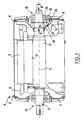
- L'invention pourra être mieux comprise à la lecture de la description détaillée qui va suivre, d'exemples de mise en oeuvre non limitatifs de celle-ci, et à l'examen du dessin annexé, sur lequel :
- la
figure 1 est une vue schématique et partielle, avec une coupe axiale de certaines pièces constitutives, d'un exemple de machine électrique à laquelle peut s'appliquer l'invention, - la
figure 2 est une vue de face, selon la flèche II de lafigure 1 , de la demi-coque intérieure de la cage, - la
figure 3 est une vue de face, selon la flèche III de lafigure 1 , de la demi-coque extérieure de la cage, - la
figure 4 est une coupe schématique selon IV-IV de lafigure 2 , - la
figure 5 est une coupe schématique selon V-V de lafigure 3 , - la
figure 6 est une coupe schématique selon VI-VI de lafigure 3 , - la
figure 7 est une demi-coupe axiale schématique de l'ensemble, les demi-coques intérieure et extérieure étant observées en coupe, selon VII-VII desfigures 2 et 3 , - la
figure 8 est une demi-coupe axiale schématique de l'ensemble, les demi-coques intérieure et extérieure étant observées en coupe, selon VIII-VIII desfigures 2 et 3 , - la
figure 9 représente un détail de l'arbre, et - la
figure 10 est une vue en coupe schématique et partielle d'une variante de réalisation. - Dans toute la description qui suit, y compris les revendications, l'expression « comportant un » doit être comprise comme signifiant « comportant au moins un », sauf si le contraire est spécifié.
- On a représenté sur la
figure 1 une machine électrique 1 comportant un stator 2 et un rotor 3 d'axe X. - Le stator 2 comporte une carcasse 4 à l'intérieur de laquelle est disposé un circuit magnétique 5 comportant un empilage de tôles magnétiques et comportant des bobinages 6, de manière conventionnelle.
- La carcasse 4 comporte des flasques d'extrémité 7 et 8 supportant chacun un ensemble 10 contenant des éléments de roulement. Les deux ensembles 10 n'ont été représentés que partiellement et très schématiquement sur la
figure 1 , dans un souci de clarté du dessin. Les deux ensembles 10 sont disposés symétriquement l'un de l'autre par rapport à un plan médian perpendiculaire à l'axe X. - Le rotor 3 comporte un arbre 12 qui porte un circuit magnétique 13 comportant un empilage de tôles magnétiques et un ventilateur 14 permettant de générer un courant d'air de refroidissement à l'intérieur de la machine.
- Chaque ensemble 10 comporte des éléments de roulement 20, constitués dans l'exemple de réalisation décrit par des billes, tournant entre deux bagues 21 et 22, la bague 21, radialement la plus intérieure, étant au contact de l'arbre 12, et la bague 22, radialement la plus extérieure, étant au contact d'une pièce intermédiaire 23 disposée entre une demi-coque intérieure 24 et une demi-coque extérieure 25, les demi-coques 24 et 25 et la pièce intermédiaire 23 constituant une cage abritant les éléments de roulement 20.
- Pour lubrifier les éléments de roulement 20, un lubrifiant est pulvérisé en continu, durant le fonctionnement de la machine, à l'intérieur de la cage par au moins un organe de pulvérisation, non représenté.
- Le lubrifiant utilisé est par exemple de l'huile.
- L'huile pulvérisée à l'intérieur de la cage peut être recueillie en un point bas de celle-ci par un orifice de vidange 27, que l'on peut voir sur la
figure 8 . - Les demi-coques 24 et 25 comportent des parties d'étanchéité annulaires respectives 30 et 31.
- Chaque partie d'étanchéité 30 ou 31 s'étend sans contact avec l'arbre et comporte des reliefs 40 destinés à s'opposer à un départ de lubrifiant par le jeu existant entre les parties d'étanchéité et l'arbre.
- Dans l'exemple illustré, ces reliefs 40 comportent des rainures hélicoïdales. La partie d'étanchéité de la demi-coque extérieure 25 peut ainsi comporter par exemple une rainure hélicoïdale 31a, 31b constituée par un filetage ISO à filet triangulaire ayant un pas de 5 mm à gauche. Une gorge 41 de récupération du lubrifiant est réalisée sur la partie filetée 31a et communique avec l'intérieur de la cage par un canal 42, comme on peut le voir sur la
figure 6 . - La partie d'étanchéité 30 de la demi-coque intérieure 24 comporte également une partie filetée 30a, 30b et une gorge de récupération 43 similaire, communiquant par un canal 44 avec l'intérieur de la cage, comme on peut le voir sur la
figure 4 . - L'arbre comporte, en regard de chaque gorge 41 ou 43 de récupération du lubrifiant, une crête annulaire 120 située au fond d'une gorge 121, la crête 120 permettant de projeter le lubrifiant présent sur l'arbre, par centrifugation, dans la gorge de récupération.
- L'orientation des filetages est choisie, compte tenu du sens de rotation de la machine, pour que les rainures tendent à ramener le lubrifiant dans la cage.
- Une gorge annulaire 50 est réalisée dans la partie d'étanchéité 31 et débouche sur l'arbre 12. Cette gorge 50 communique avec des canaux 51, au nombre de quatre dans l'exemple illustré, chacun de ces canaux 51 débouchant par un orifice 52 sur la tranche de la demi-coque extérieure 25, comme on peut le voir sur la
figure 5 . - La demi-coque intérieure 24 comporte, de manière similaire, une gorge 60 communiquant par l'intermédiaire de canaux 61, au nombre de quatre dans l'exemple illustré, avec des orifices 62 correspondants, débouchant sur sa tranche.
- Les orifices 52 sont disposés symétriquement par rapport à un plan médian vertical, comme on peut le voir sur la
figure 3 . Il en est de même des orifices 62. - On remarquera que, aussi bien pour la demi-coque intérieure 24 que pour la demi-coque extérieure 25, les parties d'étanchéité 30 et 31 comportent des régions respectives 30b et 31b, s'étendant à une faible distance de l'arbre et pourvues de reliefs tels que par exemple des rainures hélicoïdales, ces régions 30b et 31b s'étendant entre les gorges 60 et 50 et l'extrémité de la demi-coque opposée à l'autre demi-coque.
- Les canaux 51 et 61 communiquent entre eux par l'intermédiaire de canaux 70 réalisés dans la pièce intermédiaire 23, au nombre de quatre dans l'exemple illustré, ces canaux ayant des extrémités débouchant au regard des orifices 52 et 62, comme on peut le voir sur la
figure 7 . - La pièce intermédiaire 23 comporte également au moins un canal 72 permettant d'établir une communication entre deux régions 73 et 74 de la cage située de part et d'autre des éléments de roulement 20, comme on peut le voir sur la
figure 8 . Ce canal 72 permet au lubrifiant de s'écouler vers l'orifice de vidange 27. - Les canaux 51, 61 et 70 permettent d'établir une communication entre les gorges 50 et 60, qui permet de réduire les risques de fuite de lubrifiant au cours du fonctionnement de la machine 1.
- En effet, le ventilateur 14 crée une dépression à l'extérieur de l'ensemble 10 adjacent, du côté de la demi-coque intérieure 24.
- En l'absence de la communication précitée, du lubrifiant pourrait être entraîné par de l'air circulant par le jeu entre l'arbre et les parties d'étanchéité 30 et 31, en raison de la dépression précitée.
- La communication entre les gorges 50 et 60 permet de remédier à ce problème en équilibrant les pressions.
- De manière similaire, pour l'ensemble 10 situé du côté gauche de la machine, une surpression est créée par le ventilateur 14 à l'extérieur de l'ensemble 10, du côté de la demi-coque intérieure 24. En l'absence de la communication précitée, du lubrifiant pourrait être entraîné par de l'air circulant entre l'arbre et les parties d'étanchéité.
- Pour diminuer la fuite d'air de la cage vers le ventilateur 14 le long de l'arbre 12, on peut établir une communication entre les canaux 51, 61 et 70 et l'intérieur de la carcasse.
- A titre d'exemple, on a représenté à la
figure 10 un conduit 80 débouchant d'une part à la sortie 81 du ventilateur 14 à l'intérieur de la carcasse, et d'autre part dans le canal 51 de la demi-coque extérieure 25 de l'ensemble 10 situé du côté du ventilateur 14. - Ce conduit 80 permet d'amener de l'air issu du ventilateur 14 dans les gorges 50 et 60 de part et d'autre du roulement, et de refouler vers le roulement l'huile qui tendrait à s'écouler vers la dépression créée par le ventilateur 14 à l'extérieur de l'ensemble 10.
- La présence du conduit 80 est d'autant plus avantageuse lorsque la machine fonctionne avec une inclinaison tendant à faire couler le lubrifiant vers le ventilateur 14, ou s'il existe des différences de pression relativement importantes entre l'extérieur et l'intérieur de la machine du côté du ventilateur 14, notamment si la vitesse de rotation de celui-ci est élevée.
- Bien entendu, l'invention n'est pas limitée à l'exemple de réalisation qui vient d'être décrit.
- En particulier, les billes 20 peuvent être remplacées par d'autres éléments de roulement tels que par exemple des aiguilles, des rouleaux cylindriques ou coniques.
- Les éléments de roulement peuvent reprendre des efforts purement radiaux ou radiaux et axiaux.
- L'invention peut s'appliquer à des machines autres que des machines électriques tournantes, notamment des machines thermiques.
- On peut donner, sans sortir du cadre de la présente invention, des formes aux demi-coques différentes de celles illustrées et en particulier, on peut réaliser un ensemble conforme à l'invention avec seulement deux demi-coques assemblées l'une contre l'autre, sans pièce intermédiaire.
- Les canaux intérieurs de la cage peuvent être remplacés par des canaux formés au moyen de pièces rapportées. Les canaux peuvent présenter des sections diverses, circulaires ou autres.
- Le profil des rainures peut être triangulaire ou autre, notamment rectangulaire ou trapézoïdal.
Claims (25)
- Ensemble comportant une cage (24, 25 ; 23) et des éléments de roulement (20) placés à l'intérieur de la cage, les éléments de roulement étant destinés à supporter un arbre (12) traversant ladite cage, cette dernière comportant des parties d'étanchéité (30, 31) s'étendant de part et d'autre desdits éléments de roulement, l'ensemble comportant au moins une communication (51 ; 70 ; 61) entre deux espaces (50 ; 60) formés entre lesdites parties d'étanchéité (30, 31) et l'arbre (12) caractérisé par le fait qu'au moins l'une des parties d'étanchéité comporte des rainures hélicoïdales (30a ; 31a).
- Ensemble selon la revendication précédente, caractérisé par le fait que lesdits espaces sont définis par des gorges annulaires (50 ; 60) des parties d'étanchéité (31 ; 30).
- Ensemble selon l'une quelconque des revendications précédentes, caractérisé par le fait que les parties d'étanchéité (30, 31) sont sans contact avec l'arbre (12).
- Ensemble selon l'une quelconque des revendications précédentes, caractérisé par le fait que les parties d'étanchéité (30, 31) comportent des rainures (40).
- Ensemble selon l'une quelconque des revendications précédentes, caractérisé par le fait qu'il comporte des reliefs, notamment des rainures (30a, 30b ; 31a, 31b) de part et d'autre de chacun desdits espaces.
- Ensemble selon l'une quelconque des revendications précédentes, caractérisé par le fait que ladite communication comporte des canaux (51 ; 61 ; 70) réalisés à l'intérieur des parois de la cage.
- Ensemble selon l'une quelconque des revendications précédentes, caractérisé par le fait que la cage comporte au moins deux demi-coques (24, 25) disposées respectivement de part et d'autre desdits éléments de roulement (20).
- Ensemble selon la revendication 7, caractérisé par le fait que chaque demi-coque (24, 25) est réalisée d'un seul tenant avec une partie d'étanchéité, notamment par fonderie.
- Ensemble selon l'une quelconque des revendications 7 ou 8, caractérisé par le fait que la communication comporte au moins un canal intérieur (51 ; 61) réalisé dans l'une au moins des demi-coques.
- Ensemble selon l'une quelconque des revendications 7 à 9, caractérisé par le fait que la cage comporte une pièce intermédiaire (23) entre les deux demi-coques (24, 25).
- Ensemble selon la revendication précédente, caractérisé par le fait que la communication comporte au moins un canal (70) réalisé dans la pièce intermédiaire (23), notamment au moins quatre canaux (70).
- Elément selon l'une quelconque des revendications 10 ou 11, caractérisé par le fait que ladite pièce intermédiaire comporte au moins un canal (72) permettant une circulation de lubrifiant entre deux régions (73, 74) de la cage situées de part et d'autre des éléments de roulements.
- Ensemble selon la revendication précédente, caractérisé par le fait que ledit au moins un canal (72) s'étend selon un axe incliné faisant un angle non nul par rapport à l'axe (X) de l'arbre.
- Ensemble selon l'une quelconque des revendications 10 à 13, caractérisé par le fait que la pièce intermédiaire (23) est agencée pour se fixer sur des flasques d'extrémité (7, 8) d'une carcasse de machine électrique (1).
- Ensemble selon l'une quelconque des revendications précédentes, caractérisé par le fait qu'au moins l'une des parties d'étanchéité comporte une gorge (41 ; 43) de récupération d'un lubrifiant, cette gorge étant disposée entre des rainures débouchant sur l'arbre et communicant par au moins un canal (42 ; 44) avec l'intérieur de la cage.
- Ensemble selon l'une quelconque des revendications précédentes, caractérisé par le fait que les éléments de roulement comportent des billes (20).
- Ensemble selon la revendication précédente, caractérisé par le fait qu'il comporte deux bagues (21, 22) entre lesquelles les éléments de roulement (20) roulent, l'une (21) des bagues étant au contact de l'arbre, et l'autre bague (22) étant au contact de la cage.
- Ensemble selon l'une quelconque des revendications précédentes, caractérisé par le fait qu'il est adapté à recevoir un organe de pulvérisation de lubrifiant à l'intérieur de la cage.
- Ensemble selon l'une quelconque des revendications précédentes, caractérisé par le fait que le diamètre de l'arbre (12) au niveau des roulements est supérieur ou égal à 50 mm, et notamment supérieur ou égal à 100 mm.
- Ensemble selon l'une quelconque des revendications précédentes, caractérisé par le fait que la cage comporte un point bas avec un orifice de vidange (27) du lubrifiant.
- ensemble selon l'une quelconque des revendications précédentes, caractérisé par le fait que la cage est au moins partiellement remplie, en fonctionnement, par un lubrifiant qui est de l'huile.
- Machine tournante, caractérisée par le fait qu'elle comporte au moins un ensemble selon l'une quelconque des revendications 1 à 21.
- Machine selon la revendication précédente, caractérisée par le fait qu'elle comporte un ventilateur (14) à l'intérieur de sa carcasse.
- Machine selon la revendication 23, caractérisée par le fait que le ventilateur (14) est entraîné en rotation par l'arbre (12).
- Machine selon l'une des revenclications 23 ou 24, caractérisée par le fait qu'elle comporte au moins un conduit (80) débouchant d'une part dans ladite au moins une communication (51 ; 61 ; 70) et d'autre part à l'intérieur de la carcasse de la machine, à la sortie (81) du ventilateur (14).
Applications Claiming Priority (2)
| Application Number | Priority Date | Filing Date | Title |
|---|---|---|---|
| FR0200367A FR2834760B1 (fr) | 2002-01-14 | 2002-01-14 | Ensemble comportant des elements de roulement |
| FR0200367 | 2002-01-14 |
Publications (3)
| Publication Number | Publication Date |
|---|---|
| EP1327788A2 EP1327788A2 (fr) | 2003-07-16 |
| EP1327788A3 EP1327788A3 (fr) | 2007-12-05 |
| EP1327788B1 true EP1327788B1 (fr) | 2010-08-11 |
Family
ID=8871269
Family Applications (1)
| Application Number | Title | Priority Date | Filing Date |
|---|---|---|---|
| EP02292891A Expired - Lifetime EP1327788B1 (fr) | 2002-01-14 | 2002-11-21 | Ensemble comportant des éléments de roulement |
Country Status (5)
| Country | Link |
|---|---|
| US (1) | US6896412B2 (fr) |
| EP (1) | EP1327788B1 (fr) |
| AT (1) | ATE477427T1 (fr) |
| DE (1) | DE60237272D1 (fr) |
| FR (1) | FR2834760B1 (fr) |
Families Citing this family (5)
| Publication number | Priority date | Publication date | Assignee | Title |
|---|---|---|---|---|
| US7319411B2 (en) * | 2002-07-18 | 2008-01-15 | Kmg2 Sensors Corporation | Network of sensor nodes assemblies and method of remote sensing within liquid environments |
| US20070086688A1 (en) * | 2005-10-17 | 2007-04-19 | Rexnord Industries, Llc | Vented bearing assembly |
| FR2962049B1 (fr) * | 2010-07-02 | 2015-04-24 | Veolia Water Solutions & Tech | Dispositif de traitement d'eau comprenant un tambour filtrant plein |
| FR3014940B1 (fr) * | 2013-12-17 | 2016-01-15 | Poclain Hydraulics Ind | Systeme hydraulique a carter draine |
| CN106594088B (zh) * | 2015-10-19 | 2018-10-16 | 东元电机股份有限公司 | 具有油气防漏结构的轴承装置 |
Family Cites Families (10)
| Publication number | Priority date | Publication date | Assignee | Title |
|---|---|---|---|---|
| US2014859A (en) * | 1934-03-03 | 1935-09-17 | Jr David Mitchell | Bearing seal |
| US3663077A (en) * | 1971-04-22 | 1972-05-16 | Hitachi Ltd | Ball or roller bearing assembly |
| AU433891B2 (en) * | 1971-10-13 | 1973-03-19 | Hitachi Limited | Sealing device for rotary machine |
| US3774982A (en) * | 1971-12-02 | 1973-11-27 | Hitachi Ltd | Bearing device for rotary machines |
| US4257617A (en) * | 1978-11-06 | 1981-03-24 | Carrier Corporation | Shaft seal assembly |
| DE3026835A1 (de) * | 1980-07-16 | 1982-02-11 | FAG Kugelfischer Georg Schäfer & Co, 8720 Schweinfurt | Schmierfett-verteileinrichtung |
| DE3211715C2 (de) * | 1982-03-30 | 1985-06-13 | Siemens AG, 1000 Berlin und 8000 München | Druckgeschmierte Wälzlageranordnung für die Welle einer geschlossenen elektrischen Maschine |
| JPS61170251A (ja) * | 1985-01-23 | 1986-07-31 | Toshiba Corp | 車輌用電動機 |
| DE8612560U1 (de) * | 1986-05-07 | 1986-06-19 | Wilhelm Gebhardt Gmbh, 7112 Waldenburg | Lagergehäuse für ein zur Lagerung eines Ventilator-Laufrades dienendes Wälzlager |
| JPH07118880B2 (ja) * | 1986-10-15 | 1995-12-18 | フアナツク株式会社 | 高速回転用モ−タの軸受構造 |
-
2002
- 2002-01-14 FR FR0200367A patent/FR2834760B1/fr not_active Expired - Fee Related
- 2002-11-21 DE DE60237272T patent/DE60237272D1/de not_active Expired - Lifetime
- 2002-11-21 EP EP02292891A patent/EP1327788B1/fr not_active Expired - Lifetime
- 2002-11-21 AT AT02292891T patent/ATE477427T1/de active
- 2002-12-26 US US10/328,017 patent/US6896412B2/en not_active Expired - Fee Related
Also Published As
| Publication number | Publication date |
|---|---|
| ATE477427T1 (de) | 2010-08-15 |
| US20030142892A1 (en) | 2003-07-31 |
| FR2834760B1 (fr) | 2004-03-12 |
| EP1327788A2 (fr) | 2003-07-16 |
| US6896412B2 (en) | 2005-05-24 |
| FR2834760A1 (fr) | 2003-07-18 |
| EP1327788A3 (fr) | 2007-12-05 |
| DE60237272D1 (de) | 2010-09-23 |
Similar Documents
| Publication | Publication Date | Title |
|---|---|---|
| WO2008090295A2 (fr) | Cage pour roulement a billes | |
| FR2499647A1 (fr) | Perfectionnements aux accouplements magnetiques hermetiques | |
| FR2657655A1 (fr) | Pompe a vide avec des cylindres filetes helicouidalement. | |
| EP4012213B1 (fr) | Roue libre munie d'une barriere de lubrification a ouverture variable | |
| EP3738195B1 (fr) | Couronne d'équilibrage de rotor réalisée en fonderie | |
| FR3011592A1 (fr) | ||
| CA2885650A1 (fr) | Carter et roue a aubes de turbomachine | |
| FR2770586A1 (fr) | Pompe de carburant a canal lateral et moteur electrique | |
| EP0065696B1 (fr) | Butée à patins fixés | |
| EP3090182A1 (fr) | Système hydraulique à carter draine | |
| EP1327788A2 (fr) | Ensemble comportant des éléments de roulement | |
| FR2720443A1 (fr) | Joint d'étanchéité à l'huile pour turbine à gaz. | |
| EP1862683B1 (fr) | Roulement à rouleaux | |
| EP3997353B1 (fr) | Recirculation de lubrifiant dans un palier a elements roulants de turbomachine | |
| WO2017005467A1 (fr) | Coalesceur rotatif | |
| EP4077958B1 (fr) | Roulement à trois points de contact avec drain amélioré | |
| FR3021075B1 (fr) | Compresseur a spirales | |
| FR2549535A1 (fr) | Dispositif pour la separation de particules ou gouttes etrangeres de courants de gaz de fuite de turbomachines | |
| WO2021233730A1 (fr) | Sous-ensemble de compresseur basse pression d'une turbomachine d'aéronef | |
| EP3656903A1 (fr) | Dispositif de refroidissement d'une machine de formation de la foule d'un métier à tisser | |
| FR3001014A1 (fr) | Bague exterieure fixe de roulement avec au moins un orifice de drainage traversant un rebord de guidage d'au moins un element roulant | |
| FR3145741A1 (fr) | Cartouche de palier d’orientation pour aube a calage variable de rotor d’helice de turbomachine | |
| FR3156869A1 (fr) | Mécanisme de transmission à lubrification interne et ensemble de propulsion électrique associé | |
| FR2973452A1 (fr) | Pompe a engrenage interne | |
| FR2587060A1 (fr) | Dispositif de fixation de flasques sur une roue de turbine |
Legal Events
| Date | Code | Title | Description |
|---|---|---|---|
| PUAI | Public reference made under article 153(3) epc to a published international application that has entered the european phase |
Free format text: ORIGINAL CODE: 0009012 |
|
| 17P | Request for examination filed |
Effective date: 20021128 |
|
| AK | Designated contracting states |
Designated state(s): AT BE BG CH CY CZ DE DK EE ES FI FR GB GR IE IT LI LU MC NL PT SE SK TR |
|
| AX | Request for extension of the european patent |
Extension state: AL LT LV MK RO SI |
|
| PUAL | Search report despatched |
Free format text: ORIGINAL CODE: 0009013 |
|
| AK | Designated contracting states |
Kind code of ref document: A3 Designated state(s): AT BE BG CH CY CZ DE DK EE ES FI FR GB GR IE IT LI LU MC NL PT SE SK TR |
|
| AX | Request for extension of the european patent |
Extension state: AL LT LV MK RO SI |
|
| RIC1 | Information provided on ipc code assigned before grant |
Ipc: F16J 15/40 20060101ALI20071030BHEP Ipc: H02K 5/173 20060101ALI20071030BHEP Ipc: F16C 33/72 20060101ALI20071030BHEP Ipc: F16C 33/80 20060101AFI20030423BHEP Ipc: F16J 15/44 20060101ALI20071030BHEP |
|
| AKX | Designation fees paid |
Designated state(s): AT BE BG CH CY CZ DE DK EE ES FI FR GB GR IE IT LI LU MC NL PT SE SK TR |
|
| 17Q | First examination report despatched |
Effective date: 20090624 |
|
| GRAP | Despatch of communication of intention to grant a patent |
Free format text: ORIGINAL CODE: EPIDOSNIGR1 |
|
| GRAS | Grant fee paid |
Free format text: ORIGINAL CODE: EPIDOSNIGR3 |
|
| GRAA | (expected) grant |
Free format text: ORIGINAL CODE: 0009210 |
|
| AK | Designated contracting states |
Kind code of ref document: B1 Designated state(s): AT BE BG CH CY CZ DE DK EE ES FI FR GB GR IE IT LI LU MC NL PT SE SK TR |
|
| REG | Reference to a national code |
Ref country code: GB Ref legal event code: FG4D Free format text: NOT ENGLISH |
|
| REG | Reference to a national code |
Ref country code: CH Ref legal event code: EP |
|
| REG | Reference to a national code |
Ref country code: IE Ref legal event code: FG4D Free format text: LANGUAGE OF EP DOCUMENT: FRENCH |
|
| REF | Corresponds to: |
Ref document number: 60237272 Country of ref document: DE Date of ref document: 20100923 Kind code of ref document: P |
|
| REG | Reference to a national code |
Ref country code: NL Ref legal event code: VDEP Effective date: 20100811 |
|
| PG25 | Lapsed in a contracting state [announced via postgrant information from national office to epo] |
Ref country code: NL Free format text: LAPSE BECAUSE OF FAILURE TO SUBMIT A TRANSLATION OF THE DESCRIPTION OR TO PAY THE FEE WITHIN THE PRESCRIBED TIME-LIMIT Effective date: 20100811 Ref country code: FI Free format text: LAPSE BECAUSE OF FAILURE TO SUBMIT A TRANSLATION OF THE DESCRIPTION OR TO PAY THE FEE WITHIN THE PRESCRIBED TIME-LIMIT Effective date: 20100811 |
|
| PGFP | Annual fee paid to national office [announced via postgrant information from national office to epo] |
Ref country code: AT Payment date: 20101130 Year of fee payment: 9 Ref country code: FR Payment date: 20101213 Year of fee payment: 9 |
|
| PG25 | Lapsed in a contracting state [announced via postgrant information from national office to epo] |
Ref country code: PT Free format text: LAPSE BECAUSE OF FAILURE TO SUBMIT A TRANSLATION OF THE DESCRIPTION OR TO PAY THE FEE WITHIN THE PRESCRIBED TIME-LIMIT Effective date: 20101213 Ref country code: CY Free format text: LAPSE BECAUSE OF FAILURE TO SUBMIT A TRANSLATION OF THE DESCRIPTION OR TO PAY THE FEE WITHIN THE PRESCRIBED TIME-LIMIT Effective date: 20100811 Ref country code: BG Free format text: LAPSE BECAUSE OF FAILURE TO SUBMIT A TRANSLATION OF THE DESCRIPTION OR TO PAY THE FEE WITHIN THE PRESCRIBED TIME-LIMIT Effective date: 20101111 |
|
| PGFP | Annual fee paid to national office [announced via postgrant information from national office to epo] |
Ref country code: DE Payment date: 20101202 Year of fee payment: 9 |
|
| REG | Reference to a national code |
Ref country code: IE Ref legal event code: FD4D |
|
| PG25 | Lapsed in a contracting state [announced via postgrant information from national office to epo] |
Ref country code: GR Free format text: LAPSE BECAUSE OF FAILURE TO SUBMIT A TRANSLATION OF THE DESCRIPTION OR TO PAY THE FEE WITHIN THE PRESCRIBED TIME-LIMIT Effective date: 20101112 Ref country code: SE Free format text: LAPSE BECAUSE OF FAILURE TO SUBMIT A TRANSLATION OF THE DESCRIPTION OR TO PAY THE FEE WITHIN THE PRESCRIBED TIME-LIMIT Effective date: 20100811 |
|
| PGFP | Annual fee paid to national office [announced via postgrant information from national office to epo] |
Ref country code: GB Payment date: 20101119 Year of fee payment: 9 |
|
| PG25 | Lapsed in a contracting state [announced via postgrant information from national office to epo] |
Ref country code: IE Free format text: LAPSE BECAUSE OF FAILURE TO SUBMIT A TRANSLATION OF THE DESCRIPTION OR TO PAY THE FEE WITHIN THE PRESCRIBED TIME-LIMIT Effective date: 20100811 Ref country code: DK Free format text: LAPSE BECAUSE OF FAILURE TO SUBMIT A TRANSLATION OF THE DESCRIPTION OR TO PAY THE FEE WITHIN THE PRESCRIBED TIME-LIMIT Effective date: 20100811 |
|
| BERE | Be: lapsed |
Owner name: MOTEURS LEROY-SOMER Effective date: 20101130 |
|
| PG25 | Lapsed in a contracting state [announced via postgrant information from national office to epo] |
Ref country code: IT Free format text: LAPSE BECAUSE OF FAILURE TO SUBMIT A TRANSLATION OF THE DESCRIPTION OR TO PAY THE FEE WITHIN THE PRESCRIBED TIME-LIMIT Effective date: 20100811 Ref country code: EE Free format text: LAPSE BECAUSE OF FAILURE TO SUBMIT A TRANSLATION OF THE DESCRIPTION OR TO PAY THE FEE WITHIN THE PRESCRIBED TIME-LIMIT Effective date: 20100811 Ref country code: CZ Free format text: LAPSE BECAUSE OF FAILURE TO SUBMIT A TRANSLATION OF THE DESCRIPTION OR TO PAY THE FEE WITHIN THE PRESCRIBED TIME-LIMIT Effective date: 20100811 Ref country code: SK Free format text: LAPSE BECAUSE OF FAILURE TO SUBMIT A TRANSLATION OF THE DESCRIPTION OR TO PAY THE FEE WITHIN THE PRESCRIBED TIME-LIMIT Effective date: 20100811 |
|
| PLBE | No opposition filed within time limit |
Free format text: ORIGINAL CODE: 0009261 |
|
| STAA | Information on the status of an ep patent application or granted ep patent |
Free format text: STATUS: NO OPPOSITION FILED WITHIN TIME LIMIT |
|
| PG25 | Lapsed in a contracting state [announced via postgrant information from national office to epo] |
Ref country code: ES Free format text: LAPSE BECAUSE OF FAILURE TO SUBMIT A TRANSLATION OF THE DESCRIPTION OR TO PAY THE FEE WITHIN THE PRESCRIBED TIME-LIMIT Effective date: 20101122 Ref country code: MC Free format text: LAPSE BECAUSE OF NON-PAYMENT OF DUE FEES Effective date: 20101130 |
|
| REG | Reference to a national code |
Ref country code: CH Ref legal event code: PL |
|
| 26N | No opposition filed |
Effective date: 20110512 |
|
| PG25 | Lapsed in a contracting state [announced via postgrant information from national office to epo] |
Ref country code: LI Free format text: LAPSE BECAUSE OF NON-PAYMENT OF DUE FEES Effective date: 20101130 Ref country code: CH Free format text: LAPSE BECAUSE OF NON-PAYMENT OF DUE FEES Effective date: 20101130 |
|
| PG25 | Lapsed in a contracting state [announced via postgrant information from national office to epo] |
Ref country code: BE Free format text: LAPSE BECAUSE OF NON-PAYMENT OF DUE FEES Effective date: 20101130 |
|
| REG | Reference to a national code |
Ref country code: DE Ref legal event code: R097 Ref document number: 60237272 Country of ref document: DE Effective date: 20110512 |
|
| GBPC | Gb: european patent ceased through non-payment of renewal fee |
Effective date: 20111121 |
|
| REG | Reference to a national code |
Ref country code: FR Ref legal event code: ST Effective date: 20120731 |
|
| REG | Reference to a national code |
Ref country code: DE Ref legal event code: R119 Ref document number: 60237272 Country of ref document: DE Effective date: 20120601 |
|
| PG25 | Lapsed in a contracting state [announced via postgrant information from national office to epo] |
Ref country code: LU Free format text: LAPSE BECAUSE OF NON-PAYMENT OF DUE FEES Effective date: 20101121 |
|
| PG25 | Lapsed in a contracting state [announced via postgrant information from national office to epo] |
Ref country code: GB Free format text: LAPSE BECAUSE OF NON-PAYMENT OF DUE FEES Effective date: 20111121 Ref country code: TR Free format text: LAPSE BECAUSE OF FAILURE TO SUBMIT A TRANSLATION OF THE DESCRIPTION OR TO PAY THE FEE WITHIN THE PRESCRIBED TIME-LIMIT Effective date: 20100811 |
|
| REG | Reference to a national code |
Ref country code: AT Ref legal event code: MM01 Ref document number: 477427 Country of ref document: AT Kind code of ref document: T Effective date: 20111121 |
|
| PG25 | Lapsed in a contracting state [announced via postgrant information from national office to epo] |
Ref country code: FR Free format text: LAPSE BECAUSE OF NON-PAYMENT OF DUE FEES Effective date: 20111130 |
|
| PG25 | Lapsed in a contracting state [announced via postgrant information from national office to epo] |
Ref country code: AT Free format text: LAPSE BECAUSE OF NON-PAYMENT OF DUE FEES Effective date: 20111121 |
|
| PG25 | Lapsed in a contracting state [announced via postgrant information from national office to epo] |
Ref country code: DE Free format text: LAPSE BECAUSE OF NON-PAYMENT OF DUE FEES Effective date: 20120601 |