EP1327775A1 - Electromagnetic drive type plunger pump - Google Patents
Electromagnetic drive type plunger pump Download PDFInfo
- Publication number
- EP1327775A1 EP1327775A1 EP01976722A EP01976722A EP1327775A1 EP 1327775 A1 EP1327775 A1 EP 1327775A1 EP 01976722 A EP01976722 A EP 01976722A EP 01976722 A EP01976722 A EP 01976722A EP 1327775 A1 EP1327775 A1 EP 1327775A1
- Authority
- EP
- European Patent Office
- Prior art keywords
- spring
- plunger
- feeding
- urging force
- electromagnetically driven
- Prior art date
- Legal status (The legal status is an assumption and is not a legal conclusion. Google has not performed a legal analysis and makes no representation as to the accuracy of the status listed.)
- Withdrawn
Links
Images





Classifications
-
- F—MECHANICAL ENGINEERING; LIGHTING; HEATING; WEAPONS; BLASTING
- F04—POSITIVE - DISPLACEMENT MACHINES FOR LIQUIDS; PUMPS FOR LIQUIDS OR ELASTIC FLUIDS
- F04B—POSITIVE-DISPLACEMENT MACHINES FOR LIQUIDS; PUMPS
- F04B17/00—Pumps characterised by combination with, or adaptation to, specific driving engines or motors
- F04B17/03—Pumps characterised by combination with, or adaptation to, specific driving engines or motors driven by electric motors
- F04B17/04—Pumps characterised by combination with, or adaptation to, specific driving engines or motors driven by electric motors using solenoids
- F04B17/046—Pumps characterised by combination with, or adaptation to, specific driving engines or motors driven by electric motors using solenoids the fluid flowing through the moving part of the motor
-
- F—MECHANICAL ENGINEERING; LIGHTING; HEATING; WEAPONS; BLASTING
- F04—POSITIVE - DISPLACEMENT MACHINES FOR LIQUIDS; PUMPS FOR LIQUIDS OR ELASTIC FLUIDS
- F04B—POSITIVE-DISPLACEMENT MACHINES FOR LIQUIDS; PUMPS
- F04B17/00—Pumps characterised by combination with, or adaptation to, specific driving engines or motors
- F04B17/03—Pumps characterised by combination with, or adaptation to, specific driving engines or motors driven by electric motors
- F04B17/04—Pumps characterised by combination with, or adaptation to, specific driving engines or motors driven by electric motors using solenoids
Definitions
- the present invention relates to an electromagnetically driven type plunger pump, which sucks and feeds a liquid such as engine fuel and so on, and especially relates to the electromagnetically driven type plunger pump of a non-powering feed type, which sucks a liquid by the movement of a plunger and accumulates energy at a spring at a powering state, and feeds the liquid with the accumulated energy at a non-powering state.
- a conventional electromagnetically driven type plunger pump of a non-powering feed type comprises, for example, a plunger which is disposed in a cylinder (a cylindrical body) being free to reciprocate, a pair of springs which exert specific urging force to the plunger from both ends having consistent contact, a solenoid coil which exerts thrust (electromagnetic force) to the plunger to suck a liquid, a magnetic circuit including a yoke etc., various check valves, and so on.
- a pair of springs are disposed to have consistent contact with the plunger, and dampen a vibration of the plunger while retaining it at a specific resting position at a non-powered resting state with energy of the springs released, or perform together as feeding springs to accumulate the energy for feeding.
- the thrust (electromagnetic force) generated by the magnetic circuit has a characteristic that it is maximum when the plunger 3, which is urged by the pair of springs 2, is located at the vicinity of the yoke 1 which forms the magnetic circuit.
- the obtained thrust shows a mountain-shaped characteristic as being small at an early range and a later range, and being large at a middle range.
- a threshold F0 which is determined by a target discharging pressure (a feeding pressure) and the diameter (the area) of the plunger, is present.
- the plunger 3 cannot be moved towards the feeding direction when the urging force of the spring 2 does not exceed the threshold F0.
- the liquid discharging pressure (the feeding pressure) is set relatively high (200kPa ⁇ 300kPa, for example), and also with restrictions of the size of a product etc.
- the spring constant k of the spring 2 is set relatively large, resulting in that the effective stroke S of the plunger 3 is small. Accordingly, the discharging amount (the feeding amount) cannot be increased, and an increase of the power consumption or upsizing of the solenoid coil is needed to obtain a necessary discharging amount.
- the present invention is accomplished in the light of the abovementioned points, and the purpose is to provide an electromagnetically driven type plunger pump which has a high efficient discharging (feeding) performance with the effective stroke of the plunger being large, while being in a quest of simplifying the structure, downsizing, reducing power consumption, reducing noise, and so on.
- the electromagnetically driven type plunger pump of the present invention comprises a cylindrical body which forms a passage for a liquid, a plunger which is disposed having intimate contact in the passage of the cylindrical body being free to reciprocate within a specific range, a magnetic circuit including a solenoid coil which exerts mountain-shaped thrust to the plunger in accordance with the movement at a sucking process of the liquid, and a feeding spring which exerts urging force to the plunger at a feeding process, wherein the liquid is sucked by the movement of the plunger and energy is accumulated at the feeding spring at a powering state, the liquid is fed by the movement of the plunger with the energy released at a non-powering state, the spring constant of the feeding spring is set to generate urging force which is larger than the thrust in an early range of the mountain-shaped thrust, and a second spring is disposed to exert urging force to the plunger in a direction against the urging force of the feeding spring so that the urging force of the feeding spring is smaller than the thrust, at least in the early range.
- the urging force (load) of the feeding spring which is set larger than the thrust (the spring constant is relatively small) is reduced to be smaller than the thrust by the urging force (load) of the second spring which urges in the direction against the feeding spring. Therefore, the thrust can move the plunger in this early range, and the moving stroke of the plunger is enlarged, namely, the energy accumulated at the feeding spring is increased, due to the spring characteristics of the feeding spring and the second spring. Hence, a high efficient discharging (feeding) characteristic is obtained and the discharging amount (the feeding amount) of the fuel is increased.
- the second spring can be disposed to have contact and to exert the urging force to the plunger at least in the early range, and to be apart from the plunger at least in the ranges except for the early range.
- the second spring has contact and exerts the urging force to the plunger in the direction against the feeding spring at least in the early range, and only the urging force of the feeding spring is exerted to the plunger in the rest of the ranges. Therefore, compared with the case in which the second spring has consistent contact, the energy accumulated at the feeding spring can be increased.
- the spring constant of the second spring can be set larger than the spring constant of the feeding spring.
- the second spring can be disposed at the opposite side of the feeding spring sandwiching the plunger.
- the second spring can be disposed to surround the feeding spring at the outer side in the diameter direction.
- the compressed volume of when the plunger is at the full-stroke position can be reduced by the space for disposing of the second spring, and the compression rate of the fuel to be fed is increased. In this manner, the self-absorption capability can be improved.
- the plunger prefferably has a liquid passage which pierces in the axis direction, and a valve body which is capable to open the liquid passage at the sucking process and to close the fuel passage at the feeding process, and the valve body is a poppet valve to perform the opening operation by moving outwards.
- the second spring can be a coil spring with the section being rectangle-shape (angular shape).
- Fig. 1 is a sectional view showing an embodiment of an electromagnetically driven type plunger pump of the present invention.
- the electromagnetically driven type plunger pump of this embodiment feeds fuel for an engine etc. as a liquid.
- a cylinder 10 as a cylindrical body which shape is cylindrical
- a plunger 20 disposed in a passage of the cylinder 10 having intimate contact and being free to reciprocate
- a magnetic circuit including a solenoid coil 30 and a yoke 40 etc. which generate electromagnetic force to exert thrust to the plunger 20
- a feeding spring 50 which accumulates energy for feeding a liquid
- a second spring 60 which generates urging force in the direction against the urging force of the feeding spring 50, and so on, as a basic structure.
- the plunger 20 is a moving member having a specific length, which slides in the axis direction in the cylinder 10 with being free to reciprocate within a specific range.
- a fuel passage 20a is formed in the plunger 20 as a liquid passage piercing in the reciprocating direction (the axis direction).
- an enlarged passage 20b is formed at one end (the downstream side of the fuel flow) as a liquid passage enlarging the fuel passage 20a in the diameter direction.
- a check valve 21 and a coil spring 22 which urges the check valve 21 towards the upstream side, namely towards the fuel passage 20a, are disposed in the enlarged passage 20b.
- One end side of a coil spring 22 is held by an inner side end face 23b of the valve guide 23.
- a fuel passage 23c is formed to the valve guide 23 at the outer side in the diameter direction of the guide passage 23a.
- the fuel passage 20a of the plunger 20 is closed consistently with the check valve 21 which is urged by the coil spring 22. Then, when a specific pressure difference or more occurs between the rooms (the fuel passage 20a and the enlarged passage 20b) which sandwich the check valve 21 (the pressure of the fuel passage 20a side > the pressure of the enlarged passage 20b side), the check valve 21 opens the fuel passage 20a.
- the material can be resin such as rubber etc. or metal.
- a pair of ring-shaped yokes 40 which consist of a cylindrical portion 40a and a brim portion 40b, are disposed respectively with a specific gap and facing each other, at the outer side of the cylinder 10.
- a bobbin 41 is attached to the cylindrical portions 40a of the yokes 40, and a solenoid coil 30 for exciting is winded over the bobbin 41.
- the solenoid coil by passing electric current through the solenoid coil in a specific direction, magnetic force lines are generated passing through a pair of the yokes 40, the plunger 20 etc., and the thrust (electromagnetic force) to move the plunger 20 towards the left in Fig. 1 is generated.
- the characteristic of the thrust forms a mountain-shaped curve in accordance with moving strokes of the plunger 20.
- An inlet side valve support member 70 and an outlet side valve support member 80 are fixed by fitting to both end portions of the cylinder 10 respectively.
- the feeding spring 50 is disposed between the inlet side valve support member 70 and one end portion of the plunger 20, and the second spring 60 is disposed between the outlet side valve support member 80 and the other end portion of the plunger 20.
- the inlet side valve support member 70 is formed with a valve case 73 which accommodates a check valve 71 and a coil spring 72 and has a fuel passage 73a, and a valve guide 74 which has a guide passage 74a to guide a stem portion 71a of the check valve 71.
- a valve case 73 which accommodates a check valve 71 and a coil spring 72 and has a fuel passage 73a
- a valve guide 74 which has a guide passage 74a to guide a stem portion 71a of the check valve 71.
- One end side of the coil spring 72 is held by an inner end face 74b of the valve guide 74.
- the valve case 73 is fitted to the cylinder 10 with an O-ring 75.
- a fuel passage 74c is formed at the outer side in the diameter direction of the guide passage 74a.
- the fuel passage 73a of the valve case 73 is closed consistently with the check valve 71 which is urged by the coil spring 72. Then, when a specific pressure difference or more occurs between the rooms (the upstream side passage and the downstream side passage sandwiching the fuel passage 73a) which sandwich the check valve 71 (the pressure of the upstream side > the pressure of the downstream side), the check valve 71 opens the fuel passage 73a.
- the check valve 71 not limited to being hemisphere-shaped as shown in the figure, sphere-shaped or disc-shaped can be possible as the check valve 71.
- the material can also be resin such as rubber etc. or metal.
- the outlet side valve support member 80 is formed with a valve case 83 which accommodates a check valve 81 and a coil spring 82 and has a fuel passage 83a, and a valve guide 84 which has a guide passage 84a to guide a stem portion 81a of the check valve 81.
- a valve case 83 is fitted to the cylinder 10 with an O-ring 85.
- a fuel passage 84c is formed at the outer side in the diameter direction of the guide passage 84a.
- the fuel passage 83a of the valve case 83 is closed consistently with the check valve 81 which is urged by the coil spring 82. Then, when a specific pressure difference or more occurs between the rooms (the upstream side passage and the downstream side passage sandwiching the fuel passage 83a) which sandwich the check valve 81 (the pressure of the upstream side > the pressure of the downstream side), the check valve 81 opens the fuel passage 83a.
- the check valve 81 not limited to being hemisphere-shaped as shown in the figure, sphere-shaped or disc-shaped can be possible as the check valve 71.
- the material can also be resin such as rubber etc. or metal.
- an inlet side connect pipe 91 is connected to the outer side of the inlet side valve support member 70 with an O-ring 90.
- the inlet side connect pipe 91 forms a fuel passage 91a piercing in the axis direction.
- an outlet side connect pipe 93 is connected so as to cover the outlet side valve support member 80 and the cylinder 10 with an O-ring 92.
- the outlet side connect pipe 93 forms a fuel passage 93a piercing in the axis direction.
- the feeding spring 50 is a coil-shaped compression spring, and one end portion 50a has consistent contact with one end face 20d of the plunger 20, and the other end portion 50b has consistent contact with the inner side end face 73b of the valve case 73.
- the feeding spring 50 is set to have a relatively small spring constant k1, so that the generated urging force (load) F1 is larger than the thrust (load) in the early range and the later range which are the left side base part and the right side base part of the mountain-shaped thrust respectively.
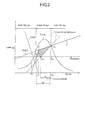
- the second spring 60 is a coil-shaped compression spring. It is disposed and fixed so that one end portion 60a is free to be in contact with or apart from the other end face 20e of the plunger 20, and the other end portion 60b is in contact with and not apart from a tubular groove bottom portion 83b of the valve case 83. As shown in Fig. 2, the second spring 60 is set to have a relatively large spring constant k2 (larger than the spring constant k1 of the feeding spring 50), so that the urging force (load) F2 is exerted to the plunger 20 in the direction against the urging force F1 of the feeding force 50 in the early range which is the left side base of the mountain-shaped thrust and in a part of the middle range.
- the urging force F2 directs against the urging force F1 of the feeding spring 50, it acts so as to eliminate the urging force of the feeding spring 50 in the abovementioned specific range.
- the resultant force F of the urging force F1 and the urging force F2 is zero (point P0) at the point of the intersection of the urging force F1 line and the urging force F2 line.
- the resultant force traces the line of the urging force F1 of the feeding spring 50 passing through the intersection (point P2) with the thrust curve. Hence, it is a polygonal line as a whole.
- the urging force of the feeding spring 50 is smaller than the thrust as a result, in the early range where the urging force F1 of the feeding spring 50 is set larger than the thrust, so that the thrust can drive the plunger 20.
- the moving stroke Sn of the plunger 20 is the distance between point P3, which is the intersection of the polygonal line indicating the resultant force F and threshold line, and point P4, which is the intersection between a perpendicular line passing through point P2 and threshold line, and is larger than the conventional stroke S. Furthermore, compared with the conventional structure, the effective energy which is accumulated at the feeding spring 50 is increased by the amount which corresponds to the area surrounded with points P1, P2, P5 and P3. Hence, a high efficient discharging (feeding) characteristic is obtained and the discharging amount (the feeding amount) of the fuel is increased than that of the conventional structure.
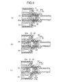
- the operation of the electromagnetically driven type plunger pump of the abovementioned embodiment is explained in accordance with Fig. 1 through Fig. 3. Firstly, the plunger 20 stays at the position (point P0) where the urging force of the feeding spring 50 and that of the second spring 60 balance at the non-powering state in which the solenoid coil 30 is not powered.
- the check valve 71 opens the fuel passage 73a against the urging force of the coil spring 72. In this manner, the fuel at the upstream of the inlet side connect pipe 91 flows into the upstream side room Su through the fuel passage 73a to be ready for the next sucking process.
- the check valve 71 allows the fuel at the specific pressure or more to flow into the upstream side room Su, and prevents to flow back, so as to contribute to reducing the self-absorption time.
- the abovementioned movement (the returning movement) of the plunger 20 corresponds to a feeding process (a discharging process) of the fuel, and the movement is performed only by the accumulated energy at the feeding spring 50.
- a feeding process a discharging process of the fuel
- the effective stroke Sn of the plunger 20 is larger than the conventional effective stroke S
- the effective energy accumulated at the feeding spring 50 is also larger.
- Fig. 4 shows another embodiment of the electromagnetically driven type plunger pump, which check valve 21 to open and close the fuel passage 20a of the plunger 20 is modified from the abovementioned embodiment.
- the same numerical note is given to the same structure as the abovementioned embodiment to omit the explanation.
- a valve seat member 100 is fitted to the enlarged passage 20b of the plunger 20.
- a poppet valve 110 is disposed being free to reciprocate so as to seat on a seat surface 101a which is located at an end portion of a fuel passage 101 formed in the valve seat member 100.
- a coil spring 111 is disposed to urge the poppet valve 110 to close the fuel passage 101 consistently.
- Fig. 5 further shows another embodiment of the electromagnetically driven type plunger pump of the present invention.
- the shape of the plunger 20 and the disposed position of the second spring 60 etc. are changed.
- the same numerical note is given to the same structure as the abovementioned embodiment to omit the explanation.
- a plunger 120 which slides in the cylinder 10 comprises a fuel passage 120a which extends in the axis direction, an enlarged passage 120b which is located at the downstream side of the fuel passage 120a, a spring hold portion 121 which is located at the upstream side of the fuel passage 120a, a flange portion 122 which is located at the end portion of the upstream side, and so on.
- the poppet valve 110 and the coil spring 111 are disposed in the enlarged passage 120b.
- the outlet side valve support member 80 which supports the check valve 81 and the coil spring 82 is disposed at the downstream side.
- the outlet side connect pipe 93 is connected at the further downstream side.
- a ring-shaped spring support member 130 is fitted to the upstream side end portion of the cylinder 10, and an inlet side connect pipe 91' is connected so as to fit to the outer circumference of the spring support member 130. Then, a feeding spring 150 is disposed in the spring hold portion 121 of the plunger 120. The feeding spring 150 is held with one end having contact with a bottom face 121a and the other end having contact with an inner end face 91b of the inlet side connect pipe 91'.
- a second spring 160 is disposed between the spring support member 130 and the flange portion 122, at the outer circumference area of the plunger 120.
- the second spring 160 is disposed so that one end is fixed to an end face 130a of the spring support member 130, and the other end is free to be in contact with or apart from the flange portion 122.
- the feeding spring 150 and the second spring 160 are set to have the characteristics as shown in Fig. 2, and the operations are the same as those of the abovementioned embodiment.
- the second spring 160 is disposed so as to surround the feeding spring 150 at the outer side in the diameter direction, the volume of the downstream side room Sd is decreased to a minimum when the plunger 120 is at the full-stroke position. In this manner, along with the advantage of the poppet valve 110, the compression rate of the fuel is increased and the self-absorption capability can be further improved.
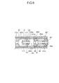
- Fig. 6 further shows another embodiment of the electromagnetically driven type plunger pump of the present invention. Compared with the abovementioned embodiment shown in Fig. 4, the second spring 60 is modified.
- the same numerical note is given to the same structure as the abovementioned embodiment to omit the explanation.
- a second spring 260 with the section being rectangle-shape (angular shape) is disposed in the downstream side room Sd which is located at the downstream side of the plunger 20.
- the second spring 260 is a coil spring being set to have the same characteristic as that of the abovementioned second spring 60. It is disposed so that one end is free to be in contact with or apart from an end face 100a of the valve seat member 100 which supports the poppet valve 110 and the coil spring 111, and the other end is fixed to an end face 83b' of the valve case 83 which constitutes the outlet side valve support member 80.
- a second spring 260 with the section being rectangle-shape (angular shape) is disposed in the downstream side room Sd which is located at the downstream side of the plunger 20.
- the second spring 260 is a coil spring being set to have the same characteristic as that of the abovementioned second spring 60. It is disposed so that one end is free to be in contact with or apart from an end face 100a of the valve seat member 100 which supports the poppet valve 110 and the coil spring 111, and the other end is fixed to an end face 83b' of the valve case 83 which constitutes the outlet side valve support member 80.
- the second spring 260 is a coil spring with the section being rectangle-shape, the compressed length can be shortened so that the volume of the downstream side room Sd is further reduced (decreased) when the plunger 20 is at the full-stroke position. In this manner, along with the advantage of the poppet valve 110, the compression rate of the fuel is increased and the self-absorption capability (self-priming) can be further improved.
- the plunger such as 20, 120, 220, in which the fuel passage is formed piercing in the axis direction
- the plunger is adopted as an application of the present invention.
- the present invention for example, to a type wherein the plunger is solid, the going movement of the plunger sucks fuel into the downstream side room Sd through the fuel passage formed at a side face of the cylinder 10, and the returning movement of the plunger feeds fuel thereafter.
- fuel for an engine etc. (gasoline, light oil) is handled as a liquid to be sucked and fed.
- various liquids such as water, oil and so on, as long as it is a liquid.
- the spring constant of a feeding spring which generates drive force for non-powering feeding (discharging)
- a second spring is disposed to exert urging force to the plunger in a direction against the urging force of the feeding spring so that the urging force of the feeding spring is smaller than the thrust, at least in the early range.
- the structure can be simplified by setting the position where the exerting of the urging force of the second spring stops to be the position where the second spring extends to the free length.
- the second spring at the outer side in the diameter direction of the feeding spring, adopting a poppet valve as a valve body which is located at the downstream side of the plunger, or adopting a coil spring with the section being rectangle-shape as the second spring, the compressed volume of when the plunger is at the full-stroke position can be reduced, and the compression rate of the fuel to be fed is increased. In this manner, the self-absorption capability can be improved.
Landscapes
- Engineering & Computer Science (AREA)
- Mechanical Engineering (AREA)
- General Engineering & Computer Science (AREA)
- Physics & Mathematics (AREA)
- Fluid Mechanics (AREA)
- Electromagnetic Pumps, Or The Like (AREA)
- Fuel-Injection Apparatus (AREA)
Abstract
With the structure comprising a cylinder 10, a magnetic circuit to exert
mountain-shaped thrust, and a feeding spring 50 to exert urging force to the
plunger 20 in a feeding process, fuel is sucked by the movement of the plunger 20
and energy is accumulated at the feeding spring 50 at a powering state, the fuel is
fed by the movement of the plunger 20 by the urging force of the feeding spring 50
at a non-powering state, the spring constant of the feeding spring 50 is set to
generate the urging force larger than the thrust in an early range of the
mountain-shaped thrust, and the second spring 60 is disposed to exert the urging
force in a direction against the urging force of the feeding spring 50 to make the
urging force smaller than the thrust, at least in the early range.
In this manner, with an electromagnetically driven type plunger pump of a
non-powering feeding type, the effective stroke is enlarged and the feeding
amount is increased.
Description
The present invention relates to an electromagnetically driven type
plunger pump, which sucks and feeds a liquid such as engine fuel and so on, and
especially relates to the electromagnetically driven type plunger pump of a
non-powering feed type, which sucks a liquid by the movement of a plunger and
accumulates energy at a spring at a powering state, and feeds the liquid with the
accumulated energy at a non-powering state.
A conventional electromagnetically driven type plunger pump of a
non-powering feed type comprises, for example, a plunger which is disposed in a
cylinder (a cylindrical body) being free to reciprocate, a pair of springs which exert
specific urging force to the plunger from both ends having consistent contact, a
solenoid coil which exerts thrust (electromagnetic force) to the plunger to suck a
liquid, a magnetic circuit including a yoke etc., various check valves, and so on.
A pair of springs are disposed to have consistent contact with the plunger,
and dampen a vibration of the plunger while retaining it at a specific resting
position at a non-powered resting state with energy of the springs released, or
perform together as feeding springs to accumulate the energy for feeding.
Further, as shown in Fig. 7, the thrust (electromagnetic force) generated
by the magnetic circuit has a characteristic that it is maximum when the plunger
3, which is urged by the pair of springs 2, is located at the vicinity of the yoke 1
which forms the magnetic circuit. In other words, the obtained thrust shows a
mountain-shaped characteristic as being small at an early range and a later range,
and being large at a middle range.
By the way, as shown in Fig. 8, with the electromagnetically driven type
plunger pump, a threshold F0, which is determined by a target discharging
pressure (a feeding pressure) and the diameter (the area) of the plunger, is
present. Here, the plunger 3 cannot be moved towards the feeding direction
when the urging force of the spring 2 does not exceed the threshold F0.
On the other hand, as shown in Fig. 8 with a two-dot chain line, it is ideal
to obtain an effective stroke Si as large as possible with the spring constant ki of
the spring 2 set relatively small, so that the feeding liquid amount (the discharged
amount) is increased with the moving stroke of the plunger 3 increased as large as
possible. However, in this case, as shown in Fig. 8 with oblique lines, the urging
force of the spring 2 exceeds the thrust at the early range. Consequently, even if
power is supplied at a sucking process, the plunger 3 cannot be operated and the
compression of the spring 2, namely the accumulation of the energy, is not
performed.
Therefore, as shown in Fig. 8, when the liquid discharging pressure (the
feeding pressure) is set relatively high (200kPa∼300kPa, for example), and also
with restrictions of the size of a product etc., the spring constant k of the spring 2
is set relatively large, resulting in that the effective stroke S of the plunger 3 is
small. Accordingly, the discharging amount (the feeding amount) cannot be
increased, and an increase of the power consumption or upsizing of the solenoid
coil is needed to obtain a necessary discharging amount.
The present invention is accomplished in the light of the abovementioned
points, and the purpose is to provide an electromagnetically driven type plunger
pump which has a high efficient discharging (feeding) performance with the
effective stroke of the plunger being large, while being in a quest of simplifying
the structure, downsizing, reducing power consumption, reducing noise, and so
on.
The electromagnetically driven type plunger pump of the present
invention comprises a cylindrical body which forms a passage for a liquid, a
plunger which is disposed having intimate contact in the passage of the
cylindrical body being free to reciprocate within a specific range, a magnetic
circuit including a solenoid coil which exerts mountain-shaped thrust to the
plunger in accordance with the movement at a sucking process of the liquid, and a
feeding spring which exerts urging force to the plunger at a feeding process,
wherein the liquid is sucked by the movement of the plunger and energy is
accumulated at the feeding spring at a powering state, the liquid is fed by the
movement of the plunger with the energy released at a non-powering state, the
spring constant of the feeding spring is set to generate urging force which is larger
than the thrust in an early range of the mountain-shaped thrust, and a second
spring is disposed to exert urging force to the plunger in a direction against the
urging force of the feeding spring so that the urging force of the feeding spring is
smaller than the thrust, at least in the early range.
With this structure, in the early range with relatively small thrust of
mountain-shaped thrust characteristic curve, the urging force (load) of the feeding
spring, which is set larger than the thrust (the spring constant is relatively small),
is reduced to be smaller than the thrust by the urging force (load) of the second
spring which urges in the direction against the feeding spring. Therefore, the
thrust can move the plunger in this early range, and the moving stroke of the
plunger is enlarged, namely, the energy accumulated at the feeding spring is
increased, due to the spring characteristics of the feeding spring and the second
spring. Hence, a high efficient discharging (feeding) characteristic is obtained
and the discharging amount (the feeding amount) of the fuel is increased.
With the abovementioned structure, the second spring can be disposed to
have contact and to exert the urging force to the plunger at least in the early
range, and to be apart from the plunger at least in the ranges except for the early
range.
With this structure, the second spring has contact and exerts the urging
force to the plunger in the direction against the feeding spring at least in the early
range, and only the urging force of the feeding spring is exerted to the plunger in
the rest of the ranges. Therefore, compared with the case in which the second
spring has consistent contact, the energy accumulated at the feeding spring can
be increased.
With the abovementioned structure, it is possible to set the second spring
to be apart from the plunger when the second spring extends to the free length.
With this structure, it is possible to make the structure simple, because
the second spring leaves the plunger automatically when the second spring
extends to the free length at which no urging force is generated.
With the abovementioned structure, the spring constant of the second
spring can be set larger than the spring constant of the feeding spring.
With this structure, desired urging force can be obtained with the
compressed length shortened. Hence, the pump can be downsized.
With the abovementioned structure, the second spring can be disposed at
the opposite side of the feeding spring sandwiching the plunger.
With this structure, it is possible to reduce noise with a simple structure,
because the plunger is supported from both sides by the springs.
With the abovementioned structure, the second spring can be disposed to
surround the feeding spring at the outer side in the diameter direction.
With this structure, the compressed volume of when the plunger is at the
full-stroke position can be reduced by the space for disposing of the second spring,
and the compression rate of the fuel to be fed is increased. In this manner, the
self-absorption capability can be improved.
With the abovementioned structure, it is possible for the plunger to have a
liquid passage which pierces in the axis direction, and a valve body which is
capable to open the liquid passage at the sucking process and to close the fuel
passage at the feeding process, and the valve body is a poppet valve to perform the
opening operation by moving outwards.
With this structure, because the outside area of the poppet valve is the
space to be compressed, the compressed volume of when the plunger is at the
full-stroke position can be reduced, and the compression rate of the fuel to be fed
is increased, as mentioned above. In this manner, the self-absorption capability
can be improved.
With the abovementioned structure, the second spring can be a coil spring
with the section being rectangle-shape (angular shape).
With this structure, because the setting length of the second spring can be
shortened, the compressed volume of when the plunger is at the full-stroke
position can be reduced, and the compression rate of the fuel to be fed is increased.
In this manner, the self-absorption capability can be improved.
The embodiments of the present invention are explained in the following
based on the attached drawings.
Fig. 1 is a sectional view showing an embodiment of an
electromagnetically driven type plunger pump of the present invention. The
electromagnetically driven type plunger pump of this embodiment feeds fuel for
an engine etc. as a liquid. As shown in Fig. 1, it comprises a cylinder 10 as a
cylindrical body which shape is cylindrical, a plunger 20 disposed in a passage of
the cylinder 10 having intimate contact and being free to reciprocate, a magnetic
circuit including a solenoid coil 30 and a yoke 40 etc. which generate
electromagnetic force to exert thrust to the plunger 20, a feeding spring 50 which
accumulates energy for feeding a liquid, a second spring 60 which generates
urging force in the direction against the urging force of the feeding spring 50, and
so on, as a basic structure.
The plunger 20 is a moving member having a specific length, which slides
in the axis direction in the cylinder 10 with being free to reciprocate within a
specific range. A fuel passage 20a is formed in the plunger 20 as a liquid passage
piercing in the reciprocating direction (the axis direction). Further, an enlarged
passage 20b is formed at one end (the downstream side of the fuel flow) as a liquid
passage enlarging the fuel passage 20a in the diameter direction.
A check valve 21 and a coil spring 22 which urges the check valve 21
towards the upstream side, namely towards the fuel passage 20a, are disposed in
the enlarged passage 20b. A valve guide 23, which forms a part of the plunger 20
and has a guide passage 23a in the center to guide a stem portion 21a of the check
valve 21, is fitted to the outer end portion of the enlarged passage 20b. One end
side of a coil spring 22 is held by an inner side end face 23b of the valve guide 23.
Here, a fuel passage 23c is formed to the valve guide 23 at the outer side in the
diameter direction of the guide passage 23a.
Consequently, the fuel passage 20a of the plunger 20 is closed consistently
with the check valve 21 which is urged by the coil spring 22. Then, when a
specific pressure difference or more occurs between the rooms (the fuel passage
20a and the enlarged passage 20b) which sandwich the check valve 21 (the
pressure of the fuel passage 20a side > the pressure of the enlarged passage 20b
side), the check valve 21 opens the fuel passage 20a. Here, not limited to being
hemisphere-shaped as shown in the figure, sphere-shaped or disc-shaped can also
be possible as the check valve 21. Furthermore, the material can be resin such
as rubber etc. or metal.
A pair of ring-shaped yokes 40, which consist of a cylindrical portion 40a
and a brim portion 40b, are disposed respectively with a specific gap and facing
each other, at the outer side of the cylinder 10. A bobbin 41 is attached to the
cylindrical portions 40a of the yokes 40, and a solenoid coil 30 for exciting is
winded over the bobbin 41.
Then, by passing electric current through the solenoid coil in a specific
direction, magnetic force lines are generated passing through a pair of the yokes
40, the plunger 20 etc., and the thrust (electromagnetic force) to move the plunger
20 towards the left in Fig. 1 is generated. As shown in Fig. 2, the characteristic
of the thrust forms a mountain-shaped curve in accordance with moving strokes of
the plunger 20.
An inlet side valve support member 70 and an outlet side valve support
member 80 are fixed by fitting to both end portions of the cylinder 10 respectively.
The feeding spring 50 is disposed between the inlet side valve support member 70
and one end portion of the plunger 20, and the second spring 60 is disposed
between the outlet side valve support member 80 and the other end portion of the
plunger 20.
The inlet side valve support member 70 is formed with a valve case 73
which accommodates a check valve 71 and a coil spring 72 and has a fuel passage
73a, and a valve guide 74 which has a guide passage 74a to guide a stem portion
71a of the check valve 71. One end side of the coil spring 72 is held by an inner
end face 74b of the valve guide 74. Here, the valve case 73 is fitted to the
cylinder 10 with an O-ring 75. At the valve guide 74 which is fitted to the valve
case 73, a fuel passage 74c is formed at the outer side in the diameter direction of
the guide passage 74a.
Consequently, the fuel passage 73a of the valve case 73 is closed
consistently with the check valve 71 which is urged by the coil spring 72. Then,
when a specific pressure difference or more occurs between the rooms (the
upstream side passage and the downstream side passage sandwiching the fuel
passage 73a) which sandwich the check valve 71 (the pressure of the upstream
side > the pressure of the downstream side), the check valve 71 opens the fuel
passage 73a. Here, not limited to being hemisphere-shaped as shown in the
figure, sphere-shaped or disc-shaped can be possible as the check valve 71.
Furthermore, the material can also be resin such as rubber etc. or metal.
The outlet side valve support member 80 is formed with a valve case 83
which accommodates a check valve 81 and a coil spring 82 and has a fuel passage
83a, and a valve guide 84 which has a guide passage 84a to guide a stem portion
81a of the check valve 81. One end side of the coil spring 82 is held by an inner
end face 84b of the valve guide 84. Here, the valve case 83 is fitted to the
cylinder 10 with an O-ring 85. At the valve guide 84 which is fitted to the valve
case 83, a fuel passage 84c is formed at the outer side in the diameter direction of
the guide passage 84a.
Consequently, the fuel passage 83a of the valve case 83 is closed
consistently with the check valve 81 which is urged by the coil spring 82. Then,
when a specific pressure difference or more occurs between the rooms (the
upstream side passage and the downstream side passage sandwiching the fuel
passage 83a) which sandwich the check valve 81 (the pressure of the upstream
side > the pressure of the downstream side), the check valve 81 opens the fuel
passage 83a. Here, not limited to being hemisphere-shaped as shown in the
figure, sphere-shaped or disc-shaped can be possible as the check valve 71.
Furthermore, the material can also be resin such as rubber etc. or metal.
Further, an inlet side connect pipe 91 is connected to the outer side of the
inlet side valve support member 70 with an O-ring 90. The inlet side connect
pipe 91 forms a fuel passage 91a piercing in the axis direction. Furthermore, an
outlet side connect pipe 93 is connected so as to cover the outlet side valve support
member 80 and the cylinder 10 with an O-ring 92. The outlet side connect pipe
93 forms a fuel passage 93a piercing in the axis direction.
The feeding spring 50 is a coil-shaped compression spring, and one end
portion 50a has consistent contact with one end face 20d of the plunger 20, and
the other end portion 50b has consistent contact with the inner side end face 73b
of the valve case 73. As shown in Fig. 2, the feeding spring 50 is set to have a
relatively small spring constant k1, so that the generated urging force (load) F1 is
larger than the thrust (load) in the early range and the later range which are the
left side base part and the right side base part of the mountain-shaped thrust
respectively.
The second spring 60 is a coil-shaped compression spring. It is disposed
and fixed so that one end portion 60a is free to be in contact with or apart from the
other end face 20e of the plunger 20, and the other end portion 60b is in contact
with and not apart from a tubular groove bottom portion 83b of the valve case 83.
As shown in Fig. 2, the second spring 60 is set to have a relatively large spring
constant k2 (larger than the spring constant k1 of the feeding spring 50), so that
the urging force (load) F2 is exerted to the plunger 20 in the direction against the
urging force F1 of the feeding force 50 in the early range which is the left side base
of the mountain-shaped thrust and in a part of the middle range.
Regarding the performance of the second spring 60, because the urging
force F2 directs against the urging force F1 of the feeding spring 50, it acts so as to
eliminate the urging force of the feeding spring 50 in the abovementioned specific
range.
Therefore, the resultant force F of the urging force F1 and the urging force
F2 is zero (point P0) at the point of the intersection of the urging force F1 line and
the urging force F2 line. At the point where the urging force F2 of the second
spring 60 is zero, only the urging force F1 of the feeding spring 50 remains (point
P1). After this point, the resultant force traces the line of the urging force F1 of
the feeding spring 50 passing through the intersection (point P2) with the thrust
curve. Hence, it is a polygonal line as a whole.
In this manner, the urging force of the feeding spring 50 is smaller than
the thrust as a result, in the early range where the urging force F1 of the feeding
spring 50 is set larger than the thrust, so that the thrust can drive the plunger 20.
Further, the moving stroke Sn of the plunger 20 is the distance between
point P3, which is the intersection of the polygonal line indicating the resultant
force F and threshold line, and point P4, which is the intersection between a
perpendicular line passing through point P2 and threshold line, and is larger than
the conventional stroke S. Furthermore, compared with the conventional
structure, the effective energy which is accumulated at the feeding spring 50 is
increased by the amount which corresponds to the area surrounded with points P1,
P2, P5 and P3. Hence, a high efficient discharging (feeding) characteristic is
obtained and the discharging amount (the feeding amount) of the fuel is increased
than that of the conventional structure.
Next, the operation of the electromagnetically driven type plunger pump
of the abovementioned embodiment is explained in accordance with Fig. 1 through
Fig. 3. Firstly, the plunger 20 stays at the position (point P0) where the urging
force of the feeding spring 50 and that of the second spring 60 balance at the
non-powering state in which the solenoid coil 30 is not powered.
At this resting state, when the solenoid coil 30 is powered and the
electromagnetic force (the thrust) is generated, the plunger 20 is pulled towards
the upstream side (towards the left side in Fig. 1) to start the going movement.
The upstream side room Su is reduced, and the downstream side room Sd is
expanded. At this time, as shown in Fig. 1 and Fig. 3 (a), the pressure in the
downstream side room Sd decreases because the check valve 81 closes the fuel
passage 83a. Then, when the pressure in the upstream side room Su becomes
larger than the pressure in the downstream side room Sd by a specific value, the
check valve 21 opens the fuel passage 20a against the urging force of the coil
spring 22. In this manner, the fuel in the upstream side room Su is sucked into
the downstream side room Sd passing through the fuel passage 20a.
Then, as shown in Fig. 2 and Fig. 3 (b), when the plunger 20 moves a
specific distance to reach point P1', the second spring 60 extends to the free length
and exerts no urging force to the plunger 20. At the same time, only the urging
force F1 of the feeding spring 50 starts to act as spring urging force to the plunger
20.
As shown in Fig. 3 (c), when the plunger 20 moves further, the free end
portion 60a of the second spring 60 is completely apart from the end face 20e of
the plunger 20. Then, when the plunger reaches point P2' in Fig. 2, the thrust by
the electromagnetic force and the urging force F1 of the feeding force 50 balance
(point P2), and the check valve 21 closes the fuel passage 20a at the same time
when the plunger 20 stops. The abovementioned movement (the going
movement) of the plunger 20 corresponds to a sucking process of the fuel. In this
sucking process, the feeding spring 50 is compressed so that the energy of the
elastic deformation is accumulated.
Next, when the powering to the solenoid coil 30 is cut off, the thrust by the
electromagnetic force is eliminated, and only the urging force F1 of the feeding
spring 50, which is increased by the compression, is exerted. As a result, the
plunger 20 starts the returning movement towards the downstream side (towards
the right side in Fig. 1). By this returning movement, the fuel sucked into the
downstream side room Sd begins to be compressed. When it reaches a specific
pressure, the check valve 81 opens the fuel passage 83a against the urging force of
the coil spring 82. In this manner, the fuel filled in the downstream side room Sd
is discharged (fed) through the outlet side connect pipe 93 at the specific pressure.
Meanwhile, as the upstream side room Su is expanded, when the pressure
of the upstream side room Su is decreased to be smaller than the pressure of the
fuel passage 91a in the inlet side connect pipe 91 by a specific value or more, the
check valve 71 opens the fuel passage 73a against the urging force of the coil
spring 72. In this manner, the fuel at the upstream of the inlet side connect pipe
91 flows into the upstream side room Su through the fuel passage 73a to be ready
for the next sucking process.
Here, the check valve 71 allows the fuel at the specific pressure or more to
flow into the upstream side room Su, and prevents to flow back, so as to contribute
to reducing the self-absorption time.
The abovementioned movement (the returning movement) of the plunger
20 corresponds to a feeding process (a discharging process) of the fuel, and the
movement is performed only by the accumulated energy at the feeding spring 50.
As shown in Fig. 2, in this feeding process, the effective stroke Sn of the plunger
20 is larger than the conventional effective stroke S, and the effective energy
accumulated at the feeding spring 50 is also larger. Hence, a high efficient
discharging (feeding) characteristic is obtained and the discharging amount (the
feeding amount) of the fuel is increased than that of the conventional structure.
Fig. 4 shows another embodiment of the electromagnetically driven type
plunger pump, which check valve 21 to open and close the fuel passage 20a of the
plunger 20 is modified from the abovementioned embodiment. Here, the same
numerical note is given to the same structure as the abovementioned embodiment
to omit the explanation.
With the electromagnetically driven type plunger pump of this
embodiment, a valve seat member 100 is fitted to the enlarged passage 20b of the
plunger 20. As a valve body, a poppet valve 110 is disposed being free to
reciprocate so as to seat on a seat surface 101a which is located at an end portion
of a fuel passage 101 formed in the valve seat member 100. Further, a coil spring
111 is disposed to urge the poppet valve 110 to close the fuel passage 101
consistently.
With this structure, because the enlarged passage 20b and the
downstream side room Sd are disconnected in the fuel feeding process, the
compression rate of the fuel is increased by the volume of the enlarged passage
20b. Hence, the self-absorption capability (the self-priming) can be further
improved.
Fig. 5 further shows another embodiment of the electromagnetically
driven type plunger pump of the present invention. Compared with the
abovementioned embodiments shown in Fig. 1 and Fig. 4, the shape of the plunger
20 and the disposed position of the second spring 60 etc. are changed. Here, the
same numerical note is given to the same structure as the abovementioned
embodiment to omit the explanation.
With the electromagnetically driven type plunger pump of this
embodiment, a plunger 120 which slides in the cylinder 10 comprises a fuel
passage 120a which extends in the axis direction, an enlarged passage 120b which
is located at the downstream side of the fuel passage 120a, a spring hold portion
121 which is located at the upstream side of the fuel passage 120a, a flange
portion 122 which is located at the end portion of the upstream side, and so on.
Then, the poppet valve 110 and the coil spring 111, as shown in Fig. 4, are
disposed in the enlarged passage 120b. The outlet side valve support member 80
which supports the check valve 81 and the coil spring 82 is disposed at the
downstream side. The outlet side connect pipe 93 is connected at the further
downstream side.
A ring-shaped spring support member 130 is fitted to the upstream side
end portion of the cylinder 10, and an inlet side connect pipe 91' is connected so as
to fit to the outer circumference of the spring support member 130. Then, a
feeding spring 150 is disposed in the spring hold portion 121 of the plunger 120.
The feeding spring 150 is held with one end having contact with a bottom face
121a and the other end having contact with an inner end face 91b of the inlet side
connect pipe 91'.
Further, a second spring 160 is disposed between the spring support
member 130 and the flange portion 122, at the outer circumference area of the
plunger 120. The second spring 160 is disposed so that one end is fixed to an end
face 130a of the spring support member 130, and the other end is free to be in
contact with or apart from the flange portion 122.
The feeding spring 150 and the second spring 160 are set to have the
characteristics as shown in Fig. 2, and the operations are the same as those of the
abovementioned embodiment.
With this structure, because the second spring 160 is disposed so as to
surround the feeding spring 150 at the outer side in the diameter direction, the
volume of the downstream side room Sd is decreased to a minimum when the
plunger 120 is at the full-stroke position. In this manner, along with the
advantage of the poppet valve 110, the compression rate of the fuel is increased
and the self-absorption capability can be further improved.
In addition, with this embodiment, as a check valve is not disposed at the
inlet side of the upstream side room Su, the fuel passage 91a' and the upstream
side room Su are consistently connected, and the rest of the operations is the same
as that of the abovementioned embodiment.
Fig. 6 further shows another embodiment of the electromagnetically
driven type plunger pump of the present invention. Compared with the
abovementioned embodiment shown in Fig. 4, the second spring 60 is modified.
Here, the same numerical note is given to the same structure as the
abovementioned embodiment to omit the explanation.
With the electromagnetically driven type plunger pump of this
embodiment, a second spring 260 with the section being rectangle-shape (angular
shape) is disposed in the downstream side room Sd which is located at the
downstream side of the plunger 20. The second spring 260 is a coil spring being
set to have the same characteristic as that of the abovementioned second spring
60. It is disposed so that one end is free to be in contact with or apart from an
end face 100a of the valve seat member 100 which supports the poppet valve 110
and the coil spring 111, and the other end is fixed to an end face 83b' of the valve
case 83 which constitutes the outlet side valve support member 80.
With the electromagnetically driven type plunger pump of this
embodiment, a second spring 260 with the section being rectangle-shape (angular
shape) is disposed in the downstream side room Sd which is located at the
downstream side of the plunger 20. The second spring 260 is a coil spring being
set to have the same characteristic as that of the abovementioned second spring
60. It is disposed so that one end is free to be in contact with or apart from an
end face 100a of the valve seat member 100 which supports the poppet valve 110
and the coil spring 111, and the other end is fixed to an end face 83b' of the valve
case 83 which constitutes the outlet side valve support member 80.
With this structure, because the second spring 260 is a coil spring with the
section being rectangle-shape, the compressed length can be shortened so that the
volume of the downstream side room Sd is further reduced (decreased) when the
plunger 20 is at the full-stroke position. In this manner, along with the
advantage of the poppet valve 110, the compression rate of the fuel is increased
and the self-absorption capability (self-priming) can be further improved.
With the abovementioned embodiments, the plunger, such as 20, 120, 220,
in which the fuel passage is formed piercing in the axis direction, is adopted as an
application of the present invention. However, not limited to this, it is certainly
possible to apply the present invention, for example, to a type wherein the plunger
is solid, the going movement of the plunger sucks fuel into the downstream side
room Sd through the fuel passage formed at a side face of the cylinder 10, and the
returning movement of the plunger feeds fuel thereafter.
Furthermore, with abovementioned embodiments, fuel for an engine etc.
(gasoline, light oil) is handled as a liquid to be sucked and fed. However, not
limited to this, it is possible to handle various liquids such as water, oil and so on,
as long as it is a liquid.
As mentioned above, with an electromagnetically driven type plunger
pump of the present invention, the spring constant of a feeding spring, which
generates drive force for non-powering feeding (discharging), is set to generate
urging force which is larger than thrust in an early range of mountain-shaped
thrust (electromagnetic force) in accordance with moving strokes of a plunger, and
a second spring is disposed to exert urging force to the plunger in a direction
against the urging force of the feeding spring so that the urging force of the
feeding spring is smaller than the thrust, at least in the early range. Because of
this structure, the plunger can be moved by the thrust in this early range, and the
moving stroke of the plunger and the accumulated energy at the feeding spring
are increased due to the spring characteristics of the feeding spring and the
second spring. In this manner, a high efficient discharging (feeding)
characteristic is obtained and the discharging amount (the feeding amount) of the
fuel is increased.
Further, the structure can be simplified by setting the position where the
exerting of the urging force of the second spring stops to be the position where the
second spring extends to the free length.
Furthermore, by disposing the second spring at the outer side in the
diameter direction of the feeding spring, adopting a poppet valve as a valve body
which is located at the downstream side of the plunger, or adopting a coil spring
with the section being rectangle-shape as the second spring, the compressed
volume of when the plunger is at the full-stroke position can be reduced, and the
compression rate of the fuel to be fed is increased. In this manner, the
self-absorption capability can be improved.
Claims (8)
- An electromagnetically driven type plunger pump, comprisinga cylindrical body which forms a passage for a liquid;a plunger which is disposed having intimate contact in said passage of said cylindrical body being free to reciprocate within a specific range;a magnetic circuit including a solenoid coil which exerts mountain-shaped thrust to said plunger in accordance with the movement at a sucking process of the liquid; anda feeding spring which exerts urging force to said plunger at a feeding process;wherein the liquid is sucked by the movement of said plunger and energy is accumulated at said feeding spring at a powering state;the liquid is fed by the movement of said plunger with said energy released at a non-powering state;the spring constant of said feeding spring is set to generate urging force which is larger than said thrust in an early range of said mountain-shaped thrust; anda second spring is disposed to exert urging force to said plunger in a direction against the urging force of said feeding spring so that the urging force of said feeding spring is smaller than said thrust, at least in said early range.
- The electromagnetically driven type plunger pump according to claim 1, wherein said second spring is disposed to have contact and to exert the urging force to said plunger at least in said early range, and to be apart from said plunger at least in the ranges except for said early range.
- The electromagnetically driven type plunger pump according to claim 2, wherein said second spring is to be apart from said plunger when said second spring extends to the free length.
- The electromagnetically driven type plunger pump according to any one of clams 1 through 3, wherein the spring constant of said second spring is set larger than the spring constant of said feeding spring.
- The electromagnetically driven type plunger pump according to any one of claims 1 through 4, wherein said second spring is disposed at the opposite side of said feeding spring sandwiching said plunger.
- The electromagnetically driven type plunger pump according to any one of claims 1 through 4, wherein said second spring is disposed to surround said feeding spring at the outer side in the diameter direction.
- The electromagnetically driven type plunger pump according to any one of claims 1 through 6;
wherein said plunger has a liquid passage which pierces in the axis direction, and a valve body which is capable to open said liquid passage at said sucking process and to close said fuel passage at said feeding process; and
said valve body is a poppet valve to perform the opening operation by moving outwards. - The electromagnetically driven type plunger pump according to any one of claims 1 through 7, wherein said second spring is a coil spring with the section being rectangle-shape.
Applications Claiming Priority (3)
| Application Number | Priority Date | Filing Date | Title |
|---|---|---|---|
| JP2000317925A JP2002130117A (en) | 2000-10-18 | 2000-10-18 | Electromagnetic driven plunger pump |
| JP2000317925 | 2000-10-18 | ||
| PCT/JP2001/009123 WO2002033259A1 (en) | 2000-10-18 | 2001-10-17 | Electromagnetic drive type plunger pump |
Publications (2)
| Publication Number | Publication Date |
|---|---|
| EP1327775A1 true EP1327775A1 (en) | 2003-07-16 |
| EP1327775A4 EP1327775A4 (en) | 2005-12-07 |
Family
ID=18796632
Family Applications (1)
| Application Number | Title | Priority Date | Filing Date |
|---|---|---|---|
| EP01976722A Withdrawn EP1327775A4 (en) | 2000-10-18 | 2001-10-17 | PLUNGER PUMP WITH ELECTROMAGNETIC CONTROL |
Country Status (6)
| Country | Link |
|---|---|
| US (1) | US7094041B2 (en) |
| EP (1) | EP1327775A4 (en) |
| JP (1) | JP2002130117A (en) |
| KR (1) | KR20030045825A (en) |
| CN (1) | CN1257347C (en) |
| WO (1) | WO2002033259A1 (en) |
Families Citing this family (30)
| Publication number | Priority date | Publication date | Assignee | Title |
|---|---|---|---|---|
| DE10147172C2 (en) * | 2001-09-25 | 2003-11-27 | Siemens Ag | Reducing agent pump for an exhaust gas aftertreatment system of an internal combustion engine |
| US20050175481A1 (en) * | 2002-09-23 | 2005-08-11 | Harbuck E. S. | Low cost fuel pump and filter assembly |
| US7150606B2 (en) * | 2003-10-28 | 2006-12-19 | Motor Components Llc | Electromagnetic fuel pump |
| CN100591914C (en) * | 2005-05-24 | 2010-02-24 | 刘明华 | Pump unit using magnetic force to drive core body |
| JP2008045508A (en) * | 2006-08-18 | 2008-02-28 | Nikki Co Ltd | Electromagnetic fuel pump |
| JP2008045507A (en) * | 2006-08-18 | 2008-02-28 | Nikki Co Ltd | Electromagnetic fuel pump |
| US20080059281A1 (en) * | 2006-08-30 | 2008-03-06 | Kimberly-Clark Worldwide, Inc. | Systems and methods for product attribute analysis and product recommendation |
| DE102008003020B4 (en) * | 2008-01-02 | 2014-05-28 | Hahn-Schickard-Gesellschaft für angewandte Forschung e.V. | Fluidic controlled fluid handling device and fluidic system having a fluidic device |
| EP2189659A1 (en) * | 2008-11-24 | 2010-05-26 | Delphi Technologies, Inc. | Fluid Pump |
| FR2960268B1 (en) * | 2010-05-21 | 2013-04-05 | Sauermann Ind Sa | ELECTROMAGNETIC OSCILLATING PISTON PUMP |
| JP5505347B2 (en) * | 2011-03-25 | 2014-05-28 | アイシン・エィ・ダブリュ株式会社 | Electromagnetic pump |
| JP5505346B2 (en) * | 2011-03-25 | 2014-05-28 | アイシン・エィ・ダブリュ株式会社 | Electromagnetic pump |
| US9004883B2 (en) * | 2011-04-01 | 2015-04-14 | Gm Global Technology Operations, Llc | Low noise high efficiency solenoid pump |
| BRPI1103647A2 (en) * | 2011-07-07 | 2013-07-02 | Whirlpool Sa | arrangement between linear compressor components |
| BRPI1103447A2 (en) * | 2011-07-19 | 2013-07-09 | Whirlpool Sa | spring bundle for compressor and spring bundled compressor |
| JP5510415B2 (en) * | 2011-08-24 | 2014-06-04 | アイシン・エィ・ダブリュ株式会社 | Electromagnetic pump |
| BRPI1104172A2 (en) * | 2011-08-31 | 2015-10-13 | Whirlpool Sa | linear compressor based on resonant oscillating mechanism |
| KR101429806B1 (en) * | 2012-01-17 | 2014-08-12 | (주)이큐베스텍 | Multi-mode apparatus for generating plasma |
| CN102723838A (en) * | 2012-07-02 | 2012-10-10 | 朱厚林 | Electromagnetic driving mechanism and electromagnetic water pump using same |
| US9816496B2 (en) * | 2014-04-25 | 2017-11-14 | Sysko Ag | Oscillating armature pump with a flux-conducting element |
| CN104265595A (en) * | 2014-09-26 | 2015-01-07 | 天纳克(苏州)排放系统有限公司 | Plunger pump with limit structure and application of plunger pump |
| JP6253623B2 (en) * | 2015-09-14 | 2017-12-27 | 本田技研工業株式会社 | Fuel shut-off valve |
| GB2543832B (en) * | 2015-10-30 | 2020-03-11 | Aspen Pumps Ltd | Pump driver |
| CN105508698A (en) * | 2016-01-15 | 2016-04-20 | 徐園植 | Self-flow oil pumping energy-saving pump electromagnetic equipment |
| CN105604886A (en) * | 2016-01-24 | 2016-05-25 | 徐園植 | Environment-friendly energy-saving vacuum pump device |
| CN105570004A (en) * | 2016-02-06 | 2016-05-11 | 徐正昌 | Efficient and safe energy-saving machine for air oxygenation |
| CN105570032A (en) * | 2016-02-06 | 2016-05-11 | 夏波 | Safety energy-saving electromagnetic equipment for pressurization transportation of heat source gas |
| CN105570054A (en) * | 2016-02-06 | 2016-05-11 | 游智强 | Air-compressing energy-saving electromagnetic pump for air braking |
| DE102018130159A1 (en) * | 2018-11-28 | 2020-05-28 | Bayerische Motoren Werke Aktiengesellschaft | Cleaning unit |
| CN112160903B (en) * | 2020-09-30 | 2025-09-30 | 杭州青谷小象科技有限公司 | A DC pump |
Family Cites Families (15)
| Publication number | Priority date | Publication date | Assignee | Title |
|---|---|---|---|---|
| US3588291A (en) * | 1969-12-05 | 1971-06-28 | Mechanical Tech Inc | Resonant piston pumps |
| US3849031A (en) * | 1973-05-04 | 1974-11-19 | Walbro Corp | Electronically controlled liquid fuel pump |
| US4101950A (en) * | 1976-11-08 | 1978-07-18 | Facet Enterprises, Inc. | Portable fluid transfer pump |
| JPS5415504A (en) * | 1977-06-10 | 1979-02-05 | Daisan Kogyo | Solenoid plunger pump |
| US4169696A (en) * | 1977-10-12 | 1979-10-02 | Facet Enterprises, Inc. | High pressure fluid pump |
| IT1130947B (en) * | 1980-03-10 | 1986-06-18 | De Dionigi Manlio | IMPROVEMENTS TO ALTERNATIVE ELECTROMAGNETIC PUMPS IN PARTICULAR FOR NON-VISCOUS FLUIDS |
| US4343597A (en) * | 1980-04-11 | 1982-08-10 | Facet Enterprises, Inc. | Reciprocating fluid pump having a hall switch |
| JPS5797191A (en) | 1980-12-05 | 1982-06-16 | Omron Tateisi Electronics Co | Ticketing device |
| JPS5797191U (en) * | 1980-12-06 | 1982-06-15 | ||
| JPH01318768A (en) | 1988-06-21 | 1989-12-25 | Ranco Japan Ltd | Drain pump |
| DE69931360T2 (en) * | 1998-03-12 | 2007-02-08 | Astellas Pharma Inc. | NEW RECIPE PROTEINS COUPLED TO A G-PROTEIN |
| DK1088164T3 (en) * | 1998-05-15 | 2003-07-14 | Rolland Versini | Motor pump with axial flow |
| KR100304587B1 (en) * | 1999-08-19 | 2001-09-24 | 구자홍 | Linear compressor |
| ATE348152T1 (en) * | 2000-12-01 | 2007-01-15 | Astellas Pharma Inc | METHOD FOR SCREENING DIABETES CURE |
| JP4149147B2 (en) * | 2001-07-19 | 2008-09-10 | 松下電器産業株式会社 | Linear compressor |
-
2000
- 2000-10-18 JP JP2000317925A patent/JP2002130117A/en active Pending
-
2001
- 2001-10-17 WO PCT/JP2001/009123 patent/WO2002033259A1/en not_active Ceased
- 2001-10-17 KR KR10-2003-7005219A patent/KR20030045825A/en not_active Withdrawn
- 2001-10-17 EP EP01976722A patent/EP1327775A4/en not_active Withdrawn
- 2001-10-17 US US10/398,807 patent/US7094041B2/en not_active Expired - Fee Related
- 2001-10-17 CN CNB018175244A patent/CN1257347C/en not_active Expired - Fee Related
Also Published As
| Publication number | Publication date |
|---|---|
| WO2002033259A1 (en) | 2002-04-25 |
| US20040022651A1 (en) | 2004-02-05 |
| US7094041B2 (en) | 2006-08-22 |
| KR20030045825A (en) | 2003-06-11 |
| JP2002130117A (en) | 2002-05-09 |
| CN1257347C (en) | 2006-05-24 |
| EP1327775A4 (en) | 2005-12-07 |
| CN1469973A (en) | 2004-01-21 |
Similar Documents
| Publication | Publication Date | Title |
|---|---|---|
| US20040022651A1 (en) | Electromagnetic drive type plunger pump | |
| JP4318730B2 (en) | High pressure fuel pump | |
| JP5316956B2 (en) | High pressure pump | |
| JP4650793B2 (en) | Pulsation damper | |
| JP2010156264A (en) | High pressure pump | |
| JP2013060945A (en) | High pressure pump | |
| JP5126605B2 (en) | High pressure pump | |
| JP5682335B2 (en) | High pressure pump | |
| US20120244014A1 (en) | Electromagnetic pump | |
| CN110651117B (en) | Valve mechanism, solenoid suction valve mechanism, and high-pressure fuel pump | |
| JP5126606B2 (en) | High pressure pump | |
| JP2000045932A (en) | Solenoid pump device | |
| US6688291B2 (en) | High-pressure fuel supply system | |
| JP3329945B2 (en) | Fuel injection device | |
| JP6032312B2 (en) | High pressure pump | |
| JP5929973B2 (en) | High pressure pump | |
| JP3782727B2 (en) | Electromagnetic pump | |
| JP5126600B2 (en) | High pressure pump | |
| JP4114301B2 (en) | Solenoid valve and fuel supply device using the same | |
| CN112204245B (en) | Fuel supply pump | |
| JP2003139262A (en) | Solenoid valve device | |
| JP6443412B2 (en) | High pressure pump | |
| JP5582235B2 (en) | High pressure pump | |
| JP2006207486A (en) | High pressure fuel pump | |
| JP5582234B2 (en) | High pressure pump |
Legal Events
| Date | Code | Title | Description |
|---|---|---|---|
| PUAI | Public reference made under article 153(3) epc to a published international application that has entered the european phase |
Free format text: ORIGINAL CODE: 0009012 |
|
| 17P | Request for examination filed |
Effective date: 20030409 |
|
| AK | Designated contracting states |
Designated state(s): DE FR GB IT |
|
| A4 | Supplementary search report drawn up and despatched |
Effective date: 20051024 |
|
| 17Q | First examination report despatched |
Effective date: 20051205 |
|
| STAA | Information on the status of an ep patent application or granted ep patent |
Free format text: STATUS: THE APPLICATION IS DEEMED TO BE WITHDRAWN |
|
| 18D | Application deemed to be withdrawn |
Effective date: 20070126 |