TECHNICAL FIELD
The present invention relates to a radial turbine used
for a turbocharger or the like for a vehicle such as an
automobile. More particularly, this invention relates to
a variable displacement turbine having movable nozzle blades
(variable nozzle).
BACKGROUND ART
In a variable displacement turbine used for a
turbocharger or the like, a plurality of movable nozzle
blades are rotatably provided between opposed two side wall
surfaces around an outer periphery of a turbine blade wheel
through shaft bodies, respectively. The nozzle discharge
angle and the passage area of an entrance of each of the
movable nozzle blades ("movable blade entrance") vary by
rotation of the movable nozzle blades, and thereby the
turbine capacity also varies.
The variable displacement turbine is provided with
a support pin which sets the clearance extending across
between the two side wall surfaces so that a distance between
the two side wall surfaces between which the movable nozzle
blade is disposed, i.e., a nozzle clearance is maintained
at an appropriate value even if the side surfaces are exposed
to high temperature gas such as exhaust gas.
The support pin is indispensable for the structure,
but since the support pin exists in working medium flow path
in the turbine entrance, the support pin becomes resistant
for the flow path, and this may become a cause for lowering
the turbine efficiency by aerodynamic influence.
Especially, aerodynamic influence of a support pin when the
quantity of flow is small is great, and reduction in turbine
efficiency when the quantity of flow is small is a problem.
Various attempts have been made for lowering the
reduction of the turbine efficiency caused by the support
pin as shown in Japanese Utility Model Application Laid-open
No. H7-25249, Japanese Patent Application Laid-open No.
H11-190219 and Japanese Patent Application Laid-open No.
H11-336554. According to the techniques described in these
publications, a mechanical structure of the support pin is
improved, the resistance of flow path caused by the support
pin is reduced, and reduction of the turbine efficiency is
lowered.
The conventional technique which improves the
mechanical structure of the support pin achieves a tentative
object, but there is a tendency that the structure of the
support pin is complicated, and there is a limit for reducing
the resistance of the flow path only by improving the
mechanical structure of the support pin. In order to obtain
better turbine efficiency, it is necessary to further reduce
the resistance of the flow path caused by the support pin.
It is an object of the present invention to provide
a variable displacement turbine capable of effectively
reducing the flow path resistance caused by a support pin,
capable of reducing aerodynamic influence of the support
pin when the quantity of flow is small, and capable of
improving the turbine efficiency when the quantity of flow
is small.
DISCLOSURE OF THE INVENTION
The present invention provides a variable displacement
turbine in which a plurality of movable nozzle blades are
rotatably provided between opposed two side wall surfaces
around an outer periphery of a turbine blade wheel by shaft
bodies, respectively, a clearance setting support pin
extending across between the two side wall surfaces is
provided in order to maintain a distance between the two
side wall surfaces at an appropriate value, wherein the
support pin is disposed at a position in front of a front
edge of the movable nozzle blade in a state in which the
movable nozzle blade is located at a rating opening position
(α = 20° ± 5°) which is set between a maximum opening position
and a minimum opening position.
With this structure, aerodynamic affect, especially
aerodynamic affect in a state of the rating opening position
to the minimum opening position is reduced by the disposition
position of the support pin with respect to the movable nozzle
blade, and efficiency on the region of small flow rate is
enhanced.
To obtain further effect, in the variable displacement
turbine of the invention, the support pin is disposed on
an extension line or in the vicinity of the extension line
of a logarithmic spiral which passes a blade thickness
central portion of the movable nozzle blade located in the
rating opening position (α = 20° ± 5°).
To obtain further effect, in the variable displacement
turbine of the invention, when an outer diameter of the
support pin is defined as d, the support pin is disposed
in a distance range away from the front edge of the movable
nozzle blade through 3d.
To obtain further effect, in the variable displacement
turbine of the invention, the disposition position of the
support pin is further defined such that the support pin
is located on the side of a negative pressure surface of
the movable nozzle blade by increasing opening of the movable
nozzle blade from the rating opening position (α = 20° ±
5°), and the support pin is located on the side of a pressure
surface of the movable nozzle blade by reducing the opening
of the movable nozzle blade from the rating opening position
(α = 20° ± 5°).
The invention also provides a variable displacement
turbine in which a plurality of movable nozzle blades are
rotatably provided between opposed two side wall surfaces
around an outer periphery of a turbine blade wheel by shaft
bodies, respectively, a clearance setting support pin
extending across between the two side wall surfaces is
provided in order to maintain a distance between the two
side wall surfaces at an appropriate value, wherein the
support pin is disposed at a position closer to a front edge
of the movable nozzle blade than a rotation center position
of the movable nozzle blade on the side of a pressure surface
of the movable nozzle blade without contacting with the
movable nozzle blade located at a maximum opening position.
With this structure also, aerodynamic affect,
especially aerodynamic affect in a state of a low opening
position is reduced by the disposition position of the
support pin with respect to the movable nozzle blade, and
efficiency on the region of small flow rate is enhanced.
To obtain further effect, the disposition position
of the support pin is further defined such that the support
pin is between a front edge position of the movable nozzle
blade and a substantially intermediate position between a
rotation center of the movable nozzle blade and the front
edge of the movable nozzle blade.
BRIEF DESCRIPTION OF THE DRAWINGS
Fig. 1 is a sectional view which shows the entire
structure when a variable displacement turbine of the present
invention is applied to a turbocharger for an automobile,
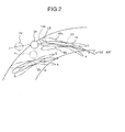
Fig. 2 is an explanatory view which shows an essential portion
of an embodiment of the variable displacement turbine of
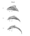
the invention, Figs. 3(a) to (c) show flow lines around
movable nozzle blades and the support pin of the invention,
Figs. 4(a) to (c) show a static pressure distribution around
the movable nozzle blades and the support pin in the variable
displacement turbine of the invention, Figs. 5(a) to (c)
show the absolute velocity distribution of flow around the
movable nozzle blades and the support pin in the variable
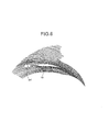
displacement turbine of the invention, Fig. 6 shows flow
lines around the movable nozzle blades and the support pin
in the variable displacement turbine of the invention, Fig.
7 shows a static pressure distribution around the movable
nozzle blades and the support pin in the variable
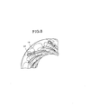
displacement turbine of the invention, Fig. 8 shows the
absolute velocity distribution of flow around the movable
nozzle blades and the support pin in the variable
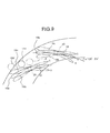
displacement turbine of the invention, Fig. 9 is an
explanatory view which shows an essential portion of another
embodiment of the variable displacement turbine of the
invention, Figs. 10(a) to (c) show flow lines around the
movable nozzle blades and the support pin in the variable
displacement turbine of the invention, Figs. 11(a) to (c)
show a static pressure distribution around the movable nozzle
blades and the support pin in the variable displacement
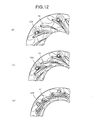
turbine of the invention, Figs . 12 (a) to (c) show the absolute
velocity distribution of flow around the movable nozzle
blades and the support pin in the variable displacement
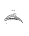
turbine of the invention, Fig. 13 shows flow lines around
the movable nozzle blades and the support pin in the variable
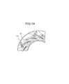
displacement turbine of the invention, Fig. 14 shows a static
pressure distribution around the movable nozzle blades and
the support pin in the variable displacement turbine of the
invention, Fig. 15 shows the absolute velocity distribution
of flow around the movable nozzle blades and the support
pin in the variable displacement turbine of the invention,
Figs. 16(a) to (c) show flow lines around the movable nozzle
blades and the support pin in a conventional variable
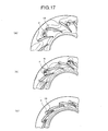
displacement turbine, Figs. 17(a) to (c) show a static
pressure distribution around the movable nozzle blades and
the support pin in the conventional variable displacement
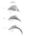
turbine, and Figs. 18(a) to (c) show the absolute velocity
distribution of flow around the movable nozzle blades and
the support pin in the conventional variable displacement
turbine.
BEST MODE FOR CARRYING OUT THE INVENTION
Embodiments of the variable displacement turbine of
the present invention will be explained in detail below with
reference to the accompanying drawings.
Fig. 1 is a sectional view which shows the entire
structure when a variable displacement turbine of the present
invention is applied to a turbocharger for an automobile.
The turbocharger comprises four housing assemblies,
i.e., a central bearing housing 1, a turbine housing 2 and
a turbine outlet housing 3 mounted to one of sides of the
bearing housing 1, and a compressor housing 4 mounted to
the other side of the bearing housing 1.
The bearing housing 1 rotatably supports a turbine
shaft 6 by a bearing 5. The turbine shaft 6 passes and extends
through the bearing housing 1 in the lateral direction as
viewed in Fig. 1. The turbine shaft 6 is integrally provided
at its one end with a turbine blade wheel 7, and a compressor
blade wheel 8 is mounted to the other end of the turbine
shaft 6.
The turbine blade wheel 7 is formed into a radial
turbine shape and has a plurality of turbine blades (movable
blades) 9. The turbine blade wheel 7 is disposed in a turbine
chamber 10 defined by the turbine housing 2. A scroll section
11 of the turbine is formed outside the turbine chamber 10
by the turbine housing 2. The compressor blade wheel 8 is
disposed in a compressor chamber 12 defined by the compressor
housing 4. A scroll section 13 of the compressor is formed
outside the compressor chamber 12 by the compressor housing
4.
An inlet passage 16 is defined around an outer periphery
of the turbine blade wheel 7, i.e., between the turbine
chamber 10 and the scroll section 11 by two opposed side
walls 14 and 15. In this embodiment, one of the side walls
14 is given by a nozzle mount member 17 fixed to the turbine
housing 2, and the other side wall 15 is given by a nozzle
plate 18 provided in the turbine housing 2.
The inlet passage 16 is of annular shape which is in
concentricity with a rotation center of the turbine blade
wheel 7. The inlet passage 16 is rotatably provided with
a plurality of movable nozzle blades 19 by shaft bodies 20,
respectively. Each of the shaft bodies 20 is operatively
connected to an operation rod 23 of an actuator 22 by a link
mechanism 21, and is rotated and driven by the actuator 22.
Each of the movable nozzle blades 19 is rotated and displaced
between a maximum opening position A, a rating opening
position (intermediate position) B and a minimum opening
position C (see Fig. 2).
In order to maintain a distance between the two opposed
side walls 14 and 15, i.e. , a size of the inlet passage 16
in its widthwise direction at an appropriate value, a support
pin 24 which sets a clearance extending across the inlet
passage 16 is provided. The support pin 24 is of columnar
shape, its one end is fixed to the nozzle mount member 17
and the other end is connected to the nozzle plate 18.
A feature of the variable displacement turbine
according to this invention resides in a positional
relationship of the support pin 24 with respect to the movable
nozzle blade 19, the disposition position of the support
pin 24 is optimized and as shown in Fig. 2, the support pin
24 is disposed in front of a front edge 19a of the movable
nozzle blade 19 in a state in which the movable nozzle blade
19 is located in the rating opening position B which is set
between the maximum opening position A and the minimum
opening position C. More specifically, the support pin 24
is disposed at a position on an extension line or in the
vicinity of the extension line of a logarithmic spiral LS
which passes a blade thickness central portion of the movable
nozzle blade 19 located in the rating opening position B
and a position extremely closer to the front edge 19a.
The rating opening position B here is an opening
corresponding to a design flow rate at which a peak efficiency
can be obtained, i.e., α is an angle of about 20°±5°.
With this disposition position, if the opening of the
movable nozzle blade 19 is increased from the rating opening
position B (turning in the clockwise direction in Fig. 2),
the support pin 24 is located on the side of a negative pressure
surface 19b of the movable nozzle blade 19, and if the opening
of the movable nozzle blade 19 is reduced from the rating
opening position B (turning in the counterclockwise
direction in Fig. 2), the support pin 24 is located on the
side of a pressure surface 19c of the movable nozzle blade
19.
Fig. 3 shows flow lines around the movable nozzle blades
19 and the support pin 24 obtained by a result of flow analysis
when the support pin 24 is located on the disposition position
as described above, Fig. 4 shows static pressure distribution
and Fig. 5 shows absolute velocity distribution. In Figs.
3 to 5, (a) shows a maximum opening position state, (b) shows
a rating opening position state and (c) shows a minimum
opening position state.
In Fig. 2, a symbol p represents a standard disposition
position of a conventional support pin. Fig. 16 shows flow
lines around the movable nozzle blade 19 and the support
pin p obtained by a result of the flow analysis in the instance
of the support pin p. Fig. 17 shows static pressure
distribution and Fig. 18 shows the absolute velocity
distribution. In Figs. 16 to 18 also, (a) shows a maximum
opening position state, (b) shows a rating opening position
state and (c) shows a minimum opening position state.
From the above flow analysis result, in the
conventional example, the support pin p aerodynamically
affects the movable nozzle blade 19 at any nozzle opening,
and especially in the minimum opening position, the support
pin p closes a passage between the nozzle blades which becomes
great flow path resistance. Whereas, with the support pin
24, there is almost no aerodynamic affect in the minimum
opening position to the rating opening position, and in the
maximum opening position, although there is a slight effect,
great pressure expansion is not generated in the vicinity
of the nozzle blade, and since the nozzle throat area is
great, it is conceived that there is no problem. With this,
the support pin 24 does not affect the movable nozzle blade
19 aerodynamically especially when the movable nozzle blade
19 is in the minimum opening position to the rating opening
position, and efficiency on the side of small flow rate is
enhanced.
Hydrodynamically, due to flow around the column
(support pin) , vortex streets generated downstream from the
column (vortex street of Karman) affect each other at
induction speed, which results to the requirement of about
three times length of the outer diameter of the column for
the vortex streets to exist stably.
With this, in order not to generate the Karman vortex,
it is preferable that the support pin 24 is disposed within
a distance range separated away from the front edge 19a of
the movable nozzle blade 19 through a distance 3d if the
outer diameter of the support pin 24 is defined as d. A
symbol 24' in Fig. 2 represents a limit example where the
support pin is disposed at a position away from the front
edge 19a of the movable nozzle blade 19 through 3d.
Fig. 6 shows flow lines around the movable nozzle blades
19 and the support pin 24' obtained by a result of the flow
analysis when the support pin 24' is disposed in the
disposition position described above, Fig. 7 shows a static
pressure distribution and Fig. 8 shows the absolute velocity
distribution. In Figs. 6 to 8, the rating opening position
state is shown as representative.
Also with the support pin 24', there is almost no
aerodynamic affect in the minimum opening position to the
rating opening position, and when the movable nozzle blade
19 is in the minimum opening position to the rating opening
position, there is almost no aerodynamic affect, and
efficiency on the side of small flow rate is enhanced.
Fig. 9 shows an essential portion of another embodiment
of the variable displacement turbine of the present invention.
In Fig. 9, portions corresponding to those in Fig. 2 are
designated with the same symbols as those in Fig. 2, and
explanation thereof will be omitted.
In this embodiment, a support pin 124 is provided on
the side of the pressure surface 19c of the movable nozzle
blade 19, the support pin 124 does not come into contact
with the movable nozzle blade 19 which is located in the
maximum opening position A, and the support pin 124 is
disposed on a position closer to the front edge 19a of the
movable nozzle blade 19 than a rotation center position
(position of the shaft body 20) of the movable nozzle blade
19.
Fig. 10 shows flow lines around the movable nozzle
blades 19 and the support pin 124 obtained by a result of
the flow analysis when the support pin 124 is disposed in
the disposition position described above, Fig. 11 shows a
static pressure distribution and Fig. 12 shows the absolute
velocity distribution. In Figs. 10 to 12 also, (a) shows
a maximum opening position state, (b) shows a rating opening
position state and (c) shows a minimum opening position
state.
From the above flow analysis result, in the
conventional example, the support pin p aerodynamically
affects the movable nozzle blade 19 at any nozzle opening
as described above, and especially in the minimum opening
position, the support pin p closes a passage between the
blades which becomes great flow path resistance. Whereas,
with the support pin 124, there is almost no aerodynamic
affect in the minimum opening, and in the rating opening
position to the maximum opening position, although there
is a slight effect, great pressure expansion is not generated
in the vicinity of the nozzle blade, and since the nozzle
throat area is great, it is conceived that there is no problem.
With this, the support pin 124 does not affect the movable
nozzle blade 19 aerodynamically especially when the movable
nozzle blade 19 is in the low opening position, and efficiency
on the side of small flow rate is enhanced.
An appropriate disposition range of the support pin
124 in this instance is about between a front edge position
(corresponding to a position of the support pin designated
with a symbol 124') of the movable nozzle blade 19 and a
substantially intermediate position (corresponding to a
position of the support pin designated with a symbol 124)
between a rotation center of the movable nozzle blade 19
and the front edge 19a of the movable nozzle blade.
Fig. 13 shows flow lines around the movable nozzle
blades 19 and the support pin 124' obtained by a result of
the flow analysis when the support pin 124' is disposed in
the disposition position described above, Fig. 14 shows a
static pressure distribution and Fig. 15 shows the absolute
velocity distribution . In Figs. 14 to 15, the rating opening
position state is shown as representative.
Also with the support pin 124', there is almost no
aerodynamic affect almost when the movable nozzle blade 19
is in the low opening position, and efficiency on the side
of small flow rate is enhanced.
As explained above, according to the variable
displacement turbine of the present invention, since the
support pin is disposed at a position in front of the movable
nozzle blade front edge in a state in which the movable nozzle
blade is located in the rating opening position (α = 20°
± 5°) which is set between the maximum opening position and
the minimum opening position, aerodynamic affect,
especially aerodynamic affect in a state of the rating
opening position to the minimum opening position is reduced
by the disposition position of the support pin with respect
to the movable nozzle blade, and efficiency on the side of
small flow rate is enhanced.
Further, according to the variable displacement
turbine of the invention, the support pin does not come into
contact with the movable nozzle blade which is located at
the maximum opening position on the side of the pressure
surface of the movable nozzle blade, and the support pin
is disposed at a position closer to the front edge of the
movable nozzle blade than the rotation center position of
the movable nozzle blade. Therefore, aerodynamic affect,
especially aerodynamic affect in a state of the low opening
position is reduced by the disposition position of the
support pin with respect to the movable nozzle blade, and
efficiency on the side of small flow rate is enhanced.
INDUSTRIAL APPLICABILITY
The variable displacement turbine of the present
invention is suitable for being used for a turbocharger for
a vehicle such as an automobile.