EP1327722A1 - Balance weight for an earthmoving machine - Google Patents
Balance weight for an earthmoving machine Download PDFInfo
- Publication number
- EP1327722A1 EP1327722A1 EP02080538A EP02080538A EP1327722A1 EP 1327722 A1 EP1327722 A1 EP 1327722A1 EP 02080538 A EP02080538 A EP 02080538A EP 02080538 A EP02080538 A EP 02080538A EP 1327722 A1 EP1327722 A1 EP 1327722A1
- Authority
- EP
- European Patent Office
- Prior art keywords
- muffler
- cavity
- machine according
- balance weight
- combustion engine
- Prior art date
- Legal status (The legal status is an assumption and is not a legal conclusion. Google has not performed a legal analysis and makes no representation as to the accuracy of the status listed.)
- Granted
Links
- 238000002485 combustion reaction Methods 0.000 claims abstract description 15
- 238000003780 insertion Methods 0.000 claims description 11
- 230000037431 insertion Effects 0.000 claims description 11
- 230000000295 complement effect Effects 0.000 claims description 2
- 230000003584 silencer Effects 0.000 description 2
- 238000004378 air conditioning Methods 0.000 description 1
- 230000004888 barrier function Effects 0.000 description 1
- 238000013016 damping Methods 0.000 description 1
- 238000009413 insulation Methods 0.000 description 1
Images


Classifications
-
- E—FIXED CONSTRUCTIONS
- E02—HYDRAULIC ENGINEERING; FOUNDATIONS; SOIL SHIFTING
- E02F—DREDGING; SOIL-SHIFTING
- E02F9/00—Component parts of dredgers or soil-shifting machines, not restricted to one of the kinds covered by groups E02F3/00 - E02F7/00
- E02F9/18—Counterweights
Definitions
- the present invention relates to a machine, in particular an earthmoving machine, of the type comprising a frame, a user-controlled operating member, and a combustion engine housed in an engine compartment and having exhaust manifolds connected to an exhaust silencer or so-called muffler.
- the muffler is normally housed in the engine compartment and connected to the frame by brackets and/or dedicated supports.
- housing the muffler inside the engine compartment is justified in order to simplify the connection to the engine exhaust outlets. In such a position, however, the muffler, which is a major source of heat, further increases the already high temperature inside the engine compartment, thus impairing operation of the parts concerned.
- the size and shape of the muffler are, in most applications, dictated by those of the engine compartment.
- a machine in particular an earthmoving machine, comprising a supporting frame, a movable operating member, a combustion engine housed in an engine compartment formed on the frame, a muffler connected to said combustion engine, and a balance weight located on the opposite side of said combustion engine with respect to said movable operating member; characterized in that said muffler is housed in said balance weight.
- said balance weight preferably at least partly defines a cavity having an opening for insertion/removal of said muffler.
- Number 1 in Figure 1 indicates as a whole a machine, in particular an earthmoving machine, comprising a supporting frame 2 movable on a carriage 3; an operating cab 4; an operating arm 5 connected to frame 2; a combustion engine 7 housed in an engine compartment 8 formed on frame 2; and a balance weight 9, or so-called ballast, connected to frame 2 on the opposite side of combustion engine 7 with respect to operating arm 5.
- balance weight 9 comprises a cavity 12 which, in the example shown, has two openings 13 for inserting/removing muffler 10. One of the openings 13 is directed towards the top, and the other one towards engine compartment 8.
- the cavity 12 is further defined at the bottom by a substantially horizontal bottom surface 14 on which muffler 10 is positioned crosswise so as to extend horizontally and perpendicularly to both the normal travelling direction 15 of machine 1 and the longitudinal members 2a of frame 2.
- Muffler 10 is locked in this position by a releasable retaining device 16 also housed in cavity 12 and which, in the embodiment described, comprises a bracket 17 integral with combustion engine 7, and two screw ties 18.
- Muffler 10 comprises an inlet sleeve 20 terminating directly inside engine compartment 8, and an outlet sleeve or tubular body 21 extending upwards and projecting rearwards and outwards of balance weight 9.
- balance weight 9 comprises a further inner wall 23 separating cavity 12, and therefore muffler 10, from engine compartment 8. Consequently, cavity 12 only communicates with the outside through an upward-facing opening 24 sized to permit insertion and removal of muffler 10 into and from cavity 12, in which the muffler is located at opening 24.
- wall 23 has a vertical slot 25 extending from and communicating with opening 24, and wider than sleeve 20.
- cavity 12 is also closed at the top by a top wall 26 of balance weight 9 integral with the rest of balance weight 9, and communicates with the outside through two facing lateral openings 27 (only one shown in Figure 4) coaxial with an axis A and formed in respective opposite lateral walls 28 of balance weight 9 facing respective sides of machine 1.
- Cavity 12 - which, in the example described, is a cavity running completely through the balance weight 9 - is substantially complementary in shape to that of muffler 10. The muffler 10 engages cavity 12 in axially-sliding manner and is inserted and removed through one of the openings 27 in a substantially horizontal direction parallel to axis A and again perpendicular to the normal travelling direction 15 and to longitudinal members 2a.
- walls 23 and 26 comprise respective horizontal slots 23a and 26a which extend from and communicate with insertion/removal opening 27, and are wider than respective sleeves 20 and 21, so that sleeves 20 and 21 slide freely inside respective slots 23a and 26a when inserting and removing the muffler into and from cavity 12.
- Muffler 10 is locked inside said cavity 12 by a releasable retaining device, which comprises, for each opening 27, a threaded U-shaped tie 30, and a bracket 31 forced onto a relative end portion of wall 23.
- muffler 10 i.e. inside balance weight or ballast 9
- balance weight or ballast 9 provides above all for reducing heat emission inside the engine compartment, thus greatly improving the operating conditions of the component parts housed in the engine compartment.
- Locating the muffler inside the ballast 9 and communicating directly with the outside also provides, on the one hand, for concealing the muffler 10 from the outside, and, on the other, for dissipating the heat produced by the muffler 10 both directly outwards - by part of the radiant surface of the muffler communicating directly with the outside at all times - and via the balance weight.
- the particular location of the muffler also provides for reducing acoustic emissions directed towards the operator, by the muffler not only being located further away from the operating cab than in known solutions, but also being housed in a body which, in addition to balancing, also acts as an effective sound barrier and vibration damping element.
- machine 1 may be of a size and shape other than those indicated, and may be connected to parts of balance weight 9 and in locations other than those described by way of example.
- machine 1 may comprise a frame and a movable arm other than those indicated, and the relative locations of the engine, cab, and movable arm may differ from those described and illustrated.
Landscapes
- Engineering & Computer Science (AREA)
- Mining & Mineral Resources (AREA)
- Civil Engineering (AREA)
- General Engineering & Computer Science (AREA)
- Structural Engineering (AREA)
- Exhaust Silencers (AREA)
- Component Parts Of Construction Machinery (AREA)
- Jib Cranes (AREA)
- Earth Drilling (AREA)
Abstract
Description
- The present invention relates to a machine, in particular an earthmoving machine, of the type comprising a frame, a user-controlled operating member, and a combustion engine housed in an engine compartment and having exhaust manifolds connected to an exhaust silencer or so-called muffler. The muffler is normally housed in the engine compartment and connected to the frame by brackets and/or dedicated supports.
- Housing the muffler inside the engine compartment is justified in order to simplify the connection to the engine exhaust outlets. In such a position, however, the muffler, which is a major source of heat, further increases the already high temperature inside the engine compartment, thus impairing operation of the parts concerned.
- Moreover, the size and shape of the muffler are, in most applications, dictated by those of the engine compartment.
- Finally, in addition to emitting heat, known mufflers are also major sources of noise, which poses serious soundproofing problems, by the muffler normally being located adjacent to the operating cab, which therefore calls for additional soundproofing and air conditioning.
- It is therefore an object of the present invention to provide a machine designed to eliminate the aforementioned drawbacks.
- According to the present invention, there is provided a machine, in particular an earthmoving machine, comprising a supporting frame, a movable operating member, a combustion engine housed in an engine compartment formed on the frame, a muffler connected to said combustion engine, and a balance weight located on the opposite side of said combustion engine with respect to said movable operating member; characterized in that said muffler is housed in said balance weight.
- In the machine defined above, said balance weight preferably at least partly defines a cavity having an opening for insertion/removal of said muffler.
- A non-limiting embodiment of the invention will now be described by way of example with reference to the accompanying drawings, in which:
- Figure 1 shows a side view of a preferred embodiment of the machine according to the present invention;
- Figure 2 shows a view in perspective, with parts removed for clarity, of a rear portion of the Figure 1 machine;
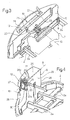
- Figure 3 is similar to, and shows a variation of, a feature in Figure 2; and
- Figure 4 shows a view in perspective, with parts removed for clarity, of a further variation of a feature in Figure 2.
-
- Number 1 in Figure 1 indicates as a whole a machine, in particular an earthmoving machine, comprising a supporting
frame 2 movable on acarriage 3; an operating cab 4; anoperating arm 5 connected toframe 2; acombustion engine 7 housed in anengine compartment 8 formed onframe 2; and abalance weight 9, or so-called ballast, connected toframe 2 on the opposite side ofcombustion engine 7 with respect tooperating arm 5. - As shown, particularly in Figures 2 to 4, the exhaust outlets of
combustion engine 7 are connected to a known elongated exhaust silencer or so-calledmuffler 10 housed insidebalance weight 9. More specifically, as shown in Figure 2,balance weight 9 comprises acavity 12 which, in the example shown, has twoopenings 13 for inserting/removingmuffler 10. One of theopenings 13 is directed towards the top, and the other one towardsengine compartment 8. Thecavity 12 is further defined at the bottom by a substantiallyhorizontal bottom surface 14 on whichmuffler 10 is positioned crosswise so as to extend horizontally and perpendicularly to both thenormal travelling direction 15 of machine 1 and thelongitudinal members 2a offrame 2. Muffler 10 is locked in this position by areleasable retaining device 16 also housed incavity 12 and which, in the embodiment described, comprises a bracket 17 integral withcombustion engine 7, and twoscrew ties 18. Muffler 10 comprises aninlet sleeve 20 terminating directly insideengine compartment 8, and an outlet sleeve ortubular body 21 extending upwards and projecting rearwards and outwards ofbalance weight 9. - In the Figure 3 variation,
balance weight 9 comprises a furtherinner wall 23 separatingcavity 12, and therefore muffler 10, fromengine compartment 8. Consequently,cavity 12 only communicates with the outside through an upward-facingopening 24 sized to permit insertion and removal ofmuffler 10 into and fromcavity 12, in which the muffler is located at opening 24. To insert and/or removemuffler 10,wall 23 has avertical slot 25 extending from and communicating with opening 24, and wider thansleeve 20. - In the Figure 4 variation,
cavity 12 is also closed at the top by atop wall 26 ofbalance weight 9 integral with the rest ofbalance weight 9, and communicates with the outside through two facing lateral openings 27 (only one shown in Figure 4) coaxial with an axis A and formed in respective oppositelateral walls 28 ofbalance weight 9 facing respective sides of machine 1. Cavity 12 - which, in the example described, is a cavity running completely through the balance weight 9 - is substantially complementary in shape to that ofmuffler 10. Themuffler 10 engagescavity 12 in axially-sliding manner and is inserted and removed through one of theopenings 27 in a substantially horizontal direction parallel to axis A and again perpendicular to thenormal travelling direction 15 and tolongitudinal members 2a. - To insert and remove
muffler 10,walls horizontal slots respective sleeves sleeves respective slots cavity 12. - Muffler 10 is locked inside said
cavity 12 by a releasable retaining device, which comprises, for eachopening 27, a threaded U-shapedtie 30, and abracket 31 forced onto a relative end portion ofwall 23. - As will be clear from the foregoing description, the particular location of
muffler 10, i.e. inside balance weight orballast 9, provides above all for reducing heat emission inside the engine compartment, thus greatly improving the operating conditions of the component parts housed in the engine compartment. - Locating the muffler inside the
ballast 9 and communicating directly with the outside also provides, on the one hand, for concealing themuffler 10 from the outside, and, on the other, for dissipating the heat produced by themuffler 10 both directly outwards - by part of the radiant surface of the muffler communicating directly with the outside at all times - and via the balance weight. - The particular location of the muffler also provides for reducing acoustic emissions directed towards the operator, by the muffler not only being located further away from the operating cab than in known solutions, but also being housed in a body which, in addition to balancing, also acts as an effective sound barrier and vibration damping element.
- As compared with known solutions, the working conditions of the operator are therefore improved, and the machine calls for less thermal insulation and soundproofing of the cab, thus reducing cost, while at the same time greatly improving appearance.
- Since a cavity of any size and/or shape can be formed in the balance weight, there is no limit to the size and/or shape of the muffler, which may therefore be selected freely at the design stage.
- Clearly, changes may be made to machine 1 as described herein without, however, departing from the scope of the present invention. In particular,
muffler 10 may be of a size and shape other than those indicated, and may be connected to parts ofbalance weight 9 and in locations other than those described by way of example. Also, machine 1 may comprise a frame and a movable arm other than those indicated, and the relative locations of the engine, cab, and movable arm may differ from those described and illustrated.
Claims (12)
- A machine (1), in particular an earthmoving machine, comprising a supporting frame (2), a movable operating member (5), a combustion engine (7) housed in an engine compartment (8) formed on the frame (2), a muffler (10) connected to said combustion engine (7), and a balance weight (9) located on the opposite side of said combustion engine (7) with respect to said movable operating member (5); and
characterized in that said muffler (10) is housed in said balance weight (9). - A machine according to claim 1, characterized in that said balance weight (9) at least partly defines a cavity (12) having an insertion/removal opening (13; 24; 27) for insertion/removal of said muffler (10).
- A machine according to claim 2, characterized in that said insertion/removal opening (13; 24) for insertion/removal of said muffler (10) faces upwards.
- A machine according to claim 3, characterized in that said muffler (10) is elongated in shape, and is positioned horizontally inside said cavity (12) and entirely at said insertion/removal opening (13; 24).
- A machine according to any one of claims 2 to 4, characterized in that said cavity (12) is defined by an inner lateral wall (23) of said balance weight (9) facing said combustion engine (7); said inner lateral wall (23) separating said cavity (12) from said engine compartment (8).
- A machine according to claim 5, characterized in that said inner lateral wall (23) comprises a slot (25) extending from said insertion/removal opening (24) and engaged by a tubular inlet body (20) of the muffler (10) terminating in said engine compartment (8); said slot (25) having transverse dimensions greater than the outer transverse dimensions of said tubular inlet body (20).
- A machine according to claim 5 or 6, characterized in that said insertion/removal opening (27) extends through a lateral wall (28) of said balance weight (9); said muffler (10) being inserted into and removed from said cavity (12) in a substantially horizontal direction.
- A machine according to claim 7, characterized in that said frame (2) comprises two longitudinal members (2a); and in that said direction is substantially perpendicular to said longitudinal members (2a).
- A machine according to claim 7 or 8, characterized in that said cavity (12) is defined at the top by a top wall (26) of said balance weight (9); said top wall (26) comprising an end slot (26a) extending from said insertion/removal opening and partly engaged by a tubular outlet body (21) of said muffler (10); said slot (26a) having transverse dimensions greater than the transverse dimensions of said tubular outlet body (21).
- A machine according to any one of claims 2 to 9, characterized in that said cavity (12) has outer dimensions greater than the corresponding outer dimensions of said muffler; releasable retaining means (16; 30,31) being provided to lock said muffler (10) inside said cavity (12).
- A machine according to claim 10, characterized in that said retaining means (16) are at least partly housed in said cavity (12).
- A machine according to any one of claims 2 to 11, characterized in that said cavity (12) is substantially complementary in shape to that of said muffler (10); and in that the muffler (10) is fitted to said cavity (12) in sliding manner.
Applications Claiming Priority (2)
| Application Number | Priority Date | Filing Date | Title |
|---|---|---|---|
| ITTO20020036 | 2002-01-11 | ||
| IT2002TO000036A ITTO20020036A1 (en) | 2002-01-11 | 2002-01-11 | OPERATING MACHINE, IN PARTICULAR FOR EARTH MOVEMENT. |
Publications (2)
| Publication Number | Publication Date |
|---|---|
| EP1327722A1 true EP1327722A1 (en) | 2003-07-16 |
| EP1327722B1 EP1327722B1 (en) | 2011-11-30 |
Family
ID=11459375
Family Applications (1)
| Application Number | Title | Priority Date | Filing Date |
|---|---|---|---|
| EP02080538A Expired - Lifetime EP1327722B1 (en) | 2002-01-11 | 2002-12-20 | Balance weight for an earthmoving machine |
Country Status (3)
| Country | Link |
|---|---|
| EP (1) | EP1327722B1 (en) |
| AT (1) | ATE535652T1 (en) |
| IT (1) | ITTO20020036A1 (en) |
Cited By (5)
| Publication number | Priority date | Publication date | Assignee | Title |
|---|---|---|---|---|
| EP2243651A4 (en) * | 2008-02-07 | 2011-10-19 | Hitachi Construction Machinery | STRUCTURE FOR ARRANGING NOx-REDUCING APPARATUS OF CONSTRUCTION MACHINE |
| EP2233714A4 (en) * | 2008-01-08 | 2012-11-28 | Hitachi Construction Machinery | MOUNTING STRUCTURE FOR NOx REDUCTION DEVICE FOR CONSTRUCTION MACHINE |
| JP2015059330A (en) * | 2013-09-18 | 2015-03-30 | キャタピラー エス エー アール エル | Counterweight device in work machines |
| JP2017166162A (en) * | 2016-03-15 | 2017-09-21 | 日立建機株式会社 | Construction machine |
| EP2679730A4 (en) * | 2011-02-25 | 2018-04-04 | Hitachi Construction Machinery Co., Ltd. | Construction machine |
Citations (9)
| Publication number | Priority date | Publication date | Assignee | Title |
|---|---|---|---|---|
| JPS5839522A (en) * | 1981-09-03 | 1983-03-08 | Nissan Motor Co Ltd | Installation structure of overhead exhaust muffler of forklift |
| JPH07277690A (en) * | 1994-04-05 | 1995-10-24 | Nissan Motor Co Ltd | Forklift counterweight exhaust structure |
| JPH09209401A (en) * | 1996-02-07 | 1997-08-12 | Hitachi Constr Mach Co Ltd | All-turn type work machine |
| JPH11139171A (en) * | 1997-11-10 | 1999-05-25 | Toyota Autom Loom Works Ltd | Radiator cooling device for forklift truck |
| JP2000080676A (en) * | 1998-09-04 | 2000-03-21 | Hitachi Constr Mach Co Ltd | Construction machinery |
| JP2000080679A (en) * | 1998-09-04 | 2000-03-21 | Hitachi Constr Mach Co Ltd | Construction machinery |
| JP2001311180A (en) * | 2000-05-01 | 2001-11-09 | Seirei Ind Co Ltd | Revolving working car |
| JP2002070077A (en) * | 2000-09-04 | 2002-03-08 | Shin Caterpillar Mitsubishi Ltd | Muffler embedded in counter weight of construction equipment |
| JP2003041627A (en) * | 2001-07-31 | 2003-02-13 | Shin Caterpillar Mitsubishi Ltd | Exhaust-gas reducer of built-in counterweight for construction machinery |
-
2002
- 2002-01-11 IT IT2002TO000036A patent/ITTO20020036A1/en unknown
- 2002-12-20 AT AT02080538T patent/ATE535652T1/en active
- 2002-12-20 EP EP02080538A patent/EP1327722B1/en not_active Expired - Lifetime
Patent Citations (9)
| Publication number | Priority date | Publication date | Assignee | Title |
|---|---|---|---|---|
| JPS5839522A (en) * | 1981-09-03 | 1983-03-08 | Nissan Motor Co Ltd | Installation structure of overhead exhaust muffler of forklift |
| JPH07277690A (en) * | 1994-04-05 | 1995-10-24 | Nissan Motor Co Ltd | Forklift counterweight exhaust structure |
| JPH09209401A (en) * | 1996-02-07 | 1997-08-12 | Hitachi Constr Mach Co Ltd | All-turn type work machine |
| JPH11139171A (en) * | 1997-11-10 | 1999-05-25 | Toyota Autom Loom Works Ltd | Radiator cooling device for forklift truck |
| JP2000080676A (en) * | 1998-09-04 | 2000-03-21 | Hitachi Constr Mach Co Ltd | Construction machinery |
| JP2000080679A (en) * | 1998-09-04 | 2000-03-21 | Hitachi Constr Mach Co Ltd | Construction machinery |
| JP2001311180A (en) * | 2000-05-01 | 2001-11-09 | Seirei Ind Co Ltd | Revolving working car |
| JP2002070077A (en) * | 2000-09-04 | 2002-03-08 | Shin Caterpillar Mitsubishi Ltd | Muffler embedded in counter weight of construction equipment |
| JP2003041627A (en) * | 2001-07-31 | 2003-02-13 | Shin Caterpillar Mitsubishi Ltd | Exhaust-gas reducer of built-in counterweight for construction machinery |
Non-Patent Citations (7)
| Title |
|---|
| PATENT ABSTRACTS OF JAPAN vol. 007, no. 120 (M - 217) 25 May 1983 (1983-05-25) * |
| PATENT ABSTRACTS OF JAPAN vol. 1996, no. 02 29 February 1996 (1996-02-29) * |
| PATENT ABSTRACTS OF JAPAN vol. 1997, no. 12 25 December 1997 (1997-12-25) * |
| PATENT ABSTRACTS OF JAPAN vol. 1999, no. 10 31 August 1999 (1999-08-31) * |
| PATENT ABSTRACTS OF JAPAN vol. 2000, no. 06 22 September 2000 (2000-09-22) * |
| PATENT ABSTRACTS OF JAPAN vol. 2002, no. 03 3 April 2002 (2002-04-03) * |
| PATENT ABSTRACTS OF JAPAN vol. 2002, no. 07 3 July 2002 (2002-07-03) * |
Cited By (7)
| Publication number | Priority date | Publication date | Assignee | Title |
|---|---|---|---|---|
| EP2233714A4 (en) * | 2008-01-08 | 2012-11-28 | Hitachi Construction Machinery | MOUNTING STRUCTURE FOR NOx REDUCTION DEVICE FOR CONSTRUCTION MACHINE |
| US8459014B2 (en) | 2008-01-08 | 2013-06-11 | Hitachi Construction Machinery Co., Ltd. | Mounting structure for NOx reduction device for construction machine |
| KR101453133B1 (en) * | 2008-01-08 | 2014-10-27 | 히다찌 겐끼 가부시키가이샤 | MOUNTING STRUCTURE FOR NOx REDUCTION DEVICE FOR CONSTRUCTION MACHINE |
| EP2243651A4 (en) * | 2008-02-07 | 2011-10-19 | Hitachi Construction Machinery | STRUCTURE FOR ARRANGING NOx-REDUCING APPARATUS OF CONSTRUCTION MACHINE |
| EP2679730A4 (en) * | 2011-02-25 | 2018-04-04 | Hitachi Construction Machinery Co., Ltd. | Construction machine |
| JP2015059330A (en) * | 2013-09-18 | 2015-03-30 | キャタピラー エス エー アール エル | Counterweight device in work machines |
| JP2017166162A (en) * | 2016-03-15 | 2017-09-21 | 日立建機株式会社 | Construction machine |
Also Published As
| Publication number | Publication date |
|---|---|
| ITTO20020036A1 (en) | 2003-07-11 |
| ATE535652T1 (en) | 2011-12-15 |
| ITTO20020036A0 (en) | 2002-01-11 |
| EP1327722B1 (en) | 2011-11-30 |
Similar Documents
| Publication | Publication Date | Title |
|---|---|---|
| CN101139962B (en) | Air intake device for two-wheeled motorcycles | |
| JP5624692B1 (en) | Bulldozer | |
| CN1097142C (en) | Silencer for two-wheel motorcycle | |
| EP1327722A1 (en) | Balance weight for an earthmoving machine | |
| JPWO2016030936A1 (en) | Bulldozer | |
| JP7009268B2 (en) | Work platform | |
| JP5271200B2 (en) | Motorcycle | |
| EP1829190A4 (en) | SENSOR SPEAKER WITH INTEGRATED COOLING DUCTS | |
| JP2005068810A (en) | Shielding device for construction machinery | |
| JP3846529B2 (en) | Intake device for internal combustion engine | |
| JP2021183815A (en) | Muffler | |
| KR100820704B1 (en) | Front mount structure of car exhaust system | |
| JP7045650B2 (en) | Heat shield structure of the cab | |
| JP4715475B2 (en) | Exhaust system mounting structure and vehicle assembly method | |
| JP2006046215A (en) | Engine intake system structure | |
| JP2014173482A (en) | Heat insulation structure of exhaust parts | |
| CN108473046B (en) | Thermal Insulation Structure of Vehicles | |
| ES2246987T3 (en) | EXHAUST GAS INSTALLATION. | |
| JPH11294278A (en) | Intake silencer | |
| KR0131152Y1 (en) | Muffler fixing hanger | |
| KR102109424B1 (en) | Muffler mounting unit for vehicle | |
| JP5698420B1 (en) | Bulldozer | |
| KR100921879B1 (en) | Muffler hanger assembly structure of vehicle | |
| JP2000045893A (en) | Engine intake system | |
| KR200151853Y1 (en) | Structure of mounting tail tube of a muffler in a fork-lift truck |
Legal Events
| Date | Code | Title | Description |
|---|---|---|---|
| PUAI | Public reference made under article 153(3) epc to a published international application that has entered the european phase |
Free format text: ORIGINAL CODE: 0009012 |
|
| AK | Designated contracting states |
Designated state(s): AT BE BG CH CY CZ DE DK EE ES FI FR GB GR IE IT LI LU MC NL PT SE SI SK TR |
|
| AX | Request for extension of the european patent |
Extension state: AL LT LV MK RO |
|
| 17P | Request for examination filed |
Effective date: 20040108 |
|
| AKX | Designation fees paid |
Designated state(s): AT BE BG CH CY CZ DE DK EE ES FI FR GB GR IE IT LI LU MC NL PT SE SK TR |
|
| 17Q | First examination report despatched |
Effective date: 20090312 |
|
| GRAP | Despatch of communication of intention to grant a patent |
Free format text: ORIGINAL CODE: EPIDOSNIGR1 |
|
| RBV | Designated contracting states (corrected) |
Designated state(s): AT BE BG CH CY CZ DE DK EE ES FI FR GB GR IE IT LI LU MC NL PT SE SI SK TR |
|
| GRAS | Grant fee paid |
Free format text: ORIGINAL CODE: EPIDOSNIGR3 |
|
| GRAA | (expected) grant |
Free format text: ORIGINAL CODE: 0009210 |
|
| AK | Designated contracting states |
Kind code of ref document: B1 Designated state(s): AT BE BG CH CY CZ DE DK EE ES FI FR GB GR IE IT LI LU MC NL PT SE SI SK TR |
|
| REG | Reference to a national code |
Ref country code: GB Ref legal event code: FG4D Ref country code: CH Ref legal event code: EP |
|
| REG | Reference to a national code |
Ref country code: IE Ref legal event code: FG4D |
|
| REG | Reference to a national code |
Ref country code: DE Ref legal event code: R096 Ref document number: 60241648 Country of ref document: DE Effective date: 20120301 |
|
| REG | Reference to a national code |
Ref country code: NL Ref legal event code: VDEP Effective date: 20111130 |
|
| PG25 | Lapsed in a contracting state [announced via postgrant information from national office to epo] |
Ref country code: NL Free format text: LAPSE BECAUSE OF FAILURE TO SUBMIT A TRANSLATION OF THE DESCRIPTION OR TO PAY THE FEE WITHIN THE PRESCRIBED TIME-LIMIT Effective date: 20111130 Ref country code: PT Free format text: LAPSE BECAUSE OF FAILURE TO SUBMIT A TRANSLATION OF THE DESCRIPTION OR TO PAY THE FEE WITHIN THE PRESCRIBED TIME-LIMIT Effective date: 20120330 Ref country code: GR Free format text: LAPSE BECAUSE OF FAILURE TO SUBMIT A TRANSLATION OF THE DESCRIPTION OR TO PAY THE FEE WITHIN THE PRESCRIBED TIME-LIMIT Effective date: 20120301 Ref country code: BE Free format text: LAPSE BECAUSE OF FAILURE TO SUBMIT A TRANSLATION OF THE DESCRIPTION OR TO PAY THE FEE WITHIN THE PRESCRIBED TIME-LIMIT Effective date: 20111130 Ref country code: SE Free format text: LAPSE BECAUSE OF FAILURE TO SUBMIT A TRANSLATION OF THE DESCRIPTION OR TO PAY THE FEE WITHIN THE PRESCRIBED TIME-LIMIT Effective date: 20111130 Ref country code: SI Free format text: LAPSE BECAUSE OF FAILURE TO SUBMIT A TRANSLATION OF THE DESCRIPTION OR TO PAY THE FEE WITHIN THE PRESCRIBED TIME-LIMIT Effective date: 20111130 |
|
| PG25 | Lapsed in a contracting state [announced via postgrant information from national office to epo] |
Ref country code: CY Free format text: LAPSE BECAUSE OF FAILURE TO SUBMIT A TRANSLATION OF THE DESCRIPTION OR TO PAY THE FEE WITHIN THE PRESCRIBED TIME-LIMIT Effective date: 20111130 |
|
| PG25 | Lapsed in a contracting state [announced via postgrant information from national office to epo] |
Ref country code: SK Free format text: LAPSE BECAUSE OF FAILURE TO SUBMIT A TRANSLATION OF THE DESCRIPTION OR TO PAY THE FEE WITHIN THE PRESCRIBED TIME-LIMIT Effective date: 20111130 Ref country code: MC Free format text: LAPSE BECAUSE OF NON-PAYMENT OF DUE FEES Effective date: 20111231 Ref country code: EE Free format text: LAPSE BECAUSE OF FAILURE TO SUBMIT A TRANSLATION OF THE DESCRIPTION OR TO PAY THE FEE WITHIN THE PRESCRIBED TIME-LIMIT Effective date: 20111130 Ref country code: DK Free format text: LAPSE BECAUSE OF FAILURE TO SUBMIT A TRANSLATION OF THE DESCRIPTION OR TO PAY THE FEE WITHIN THE PRESCRIBED TIME-LIMIT Effective date: 20111130 Ref country code: CZ Free format text: LAPSE BECAUSE OF FAILURE TO SUBMIT A TRANSLATION OF THE DESCRIPTION OR TO PAY THE FEE WITHIN THE PRESCRIBED TIME-LIMIT Effective date: 20111130 Ref country code: BG Free format text: LAPSE BECAUSE OF FAILURE TO SUBMIT A TRANSLATION OF THE DESCRIPTION OR TO PAY THE FEE WITHIN THE PRESCRIBED TIME-LIMIT Effective date: 20120229 |
|
| REG | Reference to a national code |
Ref country code: CH Ref legal event code: PL |
|
| REG | Reference to a national code |
Ref country code: AT Ref legal event code: MK05 Ref document number: 535652 Country of ref document: AT Kind code of ref document: T Effective date: 20111130 |
|
| REG | Reference to a national code |
Ref country code: IE Ref legal event code: MM4A |
|
| PLBE | No opposition filed within time limit |
Free format text: ORIGINAL CODE: 0009261 |
|
| STAA | Information on the status of an ep patent application or granted ep patent |
Free format text: STATUS: NO OPPOSITION FILED WITHIN TIME LIMIT |
|
| PG25 | Lapsed in a contracting state [announced via postgrant information from national office to epo] |
Ref country code: CH Free format text: LAPSE BECAUSE OF NON-PAYMENT OF DUE FEES Effective date: 20111231 Ref country code: IE Free format text: LAPSE BECAUSE OF NON-PAYMENT OF DUE FEES Effective date: 20111220 Ref country code: LI Free format text: LAPSE BECAUSE OF NON-PAYMENT OF DUE FEES Effective date: 20111231 |
|
| 26N | No opposition filed |
Effective date: 20120831 |
|
| REG | Reference to a national code |
Ref country code: DE Ref legal event code: R097 Ref document number: 60241648 Country of ref document: DE Effective date: 20120831 |
|
| PG25 | Lapsed in a contracting state [announced via postgrant information from national office to epo] |
Ref country code: AT Free format text: LAPSE BECAUSE OF FAILURE TO SUBMIT A TRANSLATION OF THE DESCRIPTION OR TO PAY THE FEE WITHIN THE PRESCRIBED TIME-LIMIT Effective date: 20111130 |
|
| PG25 | Lapsed in a contracting state [announced via postgrant information from national office to epo] |
Ref country code: ES Free format text: LAPSE BECAUSE OF FAILURE TO SUBMIT A TRANSLATION OF THE DESCRIPTION OR TO PAY THE FEE WITHIN THE PRESCRIBED TIME-LIMIT Effective date: 20120311 |
|
| PG25 | Lapsed in a contracting state [announced via postgrant information from national office to epo] |
Ref country code: LU Free format text: LAPSE BECAUSE OF NON-PAYMENT OF DUE FEES Effective date: 20111220 |
|
| PG25 | Lapsed in a contracting state [announced via postgrant information from national office to epo] |
Ref country code: FI Free format text: LAPSE BECAUSE OF FAILURE TO SUBMIT A TRANSLATION OF THE DESCRIPTION OR TO PAY THE FEE WITHIN THE PRESCRIBED TIME-LIMIT Effective date: 20111130 |
|
| PG25 | Lapsed in a contracting state [announced via postgrant information from national office to epo] |
Ref country code: TR Free format text: LAPSE BECAUSE OF FAILURE TO SUBMIT A TRANSLATION OF THE DESCRIPTION OR TO PAY THE FEE WITHIN THE PRESCRIBED TIME-LIMIT Effective date: 20111130 |
|
| REG | Reference to a national code |
Ref country code: FR Ref legal event code: PLFP Year of fee payment: 14 |
|
| REG | Reference to a national code |
Ref country code: FR Ref legal event code: PLFP Year of fee payment: 15 |
|
| REG | Reference to a national code |
Ref country code: FR Ref legal event code: PLFP Year of fee payment: 16 |
|
| PGFP | Annual fee paid to national office [announced via postgrant information from national office to epo] |
Ref country code: DE Payment date: 20171011 Year of fee payment: 16 |
|
| REG | Reference to a national code |
Ref country code: FR Ref legal event code: PLFP Year of fee payment: 17 |
|
| PGFP | Annual fee paid to national office [announced via postgrant information from national office to epo] |
Ref country code: GB Payment date: 20181011 Year of fee payment: 17 Ref country code: FR Payment date: 20181018 Year of fee payment: 17 Ref country code: IT Payment date: 20181210 Year of fee payment: 17 |
|
| REG | Reference to a national code |
Ref country code: DE Ref legal event code: R119 Ref document number: 60241648 Country of ref document: DE |
|
| PG25 | Lapsed in a contracting state [announced via postgrant information from national office to epo] |
Ref country code: DE Free format text: LAPSE BECAUSE OF NON-PAYMENT OF DUE FEES Effective date: 20190702 |
|
| GBPC | Gb: european patent ceased through non-payment of renewal fee |
Effective date: 20191220 |
|
| PG25 | Lapsed in a contracting state [announced via postgrant information from national office to epo] |
Ref country code: FR Free format text: LAPSE BECAUSE OF NON-PAYMENT OF DUE FEES Effective date: 20191231 Ref country code: GB Free format text: LAPSE BECAUSE OF NON-PAYMENT OF DUE FEES Effective date: 20191220 Ref country code: IT Free format text: LAPSE BECAUSE OF NON-PAYMENT OF DUE FEES Effective date: 20191220 |