EP1327593A1 - Apparatus and method for picking printing plates of various sizes - Google Patents
Apparatus and method for picking printing plates of various sizes Download PDFInfo
- Publication number
- EP1327593A1 EP1327593A1 EP03100039A EP03100039A EP1327593A1 EP 1327593 A1 EP1327593 A1 EP 1327593A1 EP 03100039 A EP03100039 A EP 03100039A EP 03100039 A EP03100039 A EP 03100039A EP 1327593 A1 EP1327593 A1 EP 1327593A1
- Authority
- EP
- European Patent Office
- Prior art keywords
- suction cups
- vacuum
- printing plate
- vacuum source
- coupled
- Prior art date
- Legal status (The legal status is an assumption and is not a legal conclusion. Google has not performed a legal analysis and makes no representation as to the accuracy of the status listed.)
- Granted
Links
- 238000000034 method Methods 0.000 title claims description 9
- 238000003384 imaging method Methods 0.000 claims description 26
- 230000008878 coupling Effects 0.000 claims description 9
- 238000010168 coupling process Methods 0.000 claims description 9
- 238000005859 coupling reaction Methods 0.000 claims description 9
- 230000007246 mechanism Effects 0.000 description 5
- 230000003287 optical effect Effects 0.000 description 4
- 230000005855 radiation Effects 0.000 description 4
- 238000010409 ironing Methods 0.000 description 2
- 238000012986 modification Methods 0.000 description 2
- 230000004048 modification Effects 0.000 description 2
- XAGFODPZIPBFFR-UHFFFAOYSA-N aluminium Chemical compound [Al] XAGFODPZIPBFFR-UHFFFAOYSA-N 0.000 description 1
- 229910052782 aluminium Inorganic materials 0.000 description 1
- 230000001419 dependent effect Effects 0.000 description 1
- 238000003708 edge detection Methods 0.000 description 1
- 230000000694 effects Effects 0.000 description 1
- 229920000728 polyester Polymers 0.000 description 1
- 230000001681 protective effect Effects 0.000 description 1
- 239000000758 substrate Substances 0.000 description 1
Images







Classifications
-
- B—PERFORMING OPERATIONS; TRANSPORTING
- B65—CONVEYING; PACKING; STORING; HANDLING THIN OR FILAMENTARY MATERIAL
- B65H—HANDLING THIN OR FILAMENTARY MATERIAL, e.g. SHEETS, WEBS, CABLES
- B65H3/00—Separating articles from piles
- B65H3/32—Separating articles from piles by elements, e.g. fingers, plates, rollers, inserted or traversed between articles to be separated and remainder of the pile
-
- B—PERFORMING OPERATIONS; TRANSPORTING
- B65—CONVEYING; PACKING; STORING; HANDLING THIN OR FILAMENTARY MATERIAL
- B65H—HANDLING THIN OR FILAMENTARY MATERIAL, e.g. SHEETS, WEBS, CABLES
- B65H3/00—Separating articles from piles
- B65H3/08—Separating articles from piles using pneumatic force
- B65H3/0808—Suction grippers
- B65H3/0883—Construction of suction grippers or their holding devices
-
- B—PERFORMING OPERATIONS; TRANSPORTING
- B65—CONVEYING; PACKING; STORING; HANDLING THIN OR FILAMENTARY MATERIAL
- B65H—HANDLING THIN OR FILAMENTARY MATERIAL, e.g. SHEETS, WEBS, CABLES
- B65H2301/00—Handling processes for sheets or webs
- B65H2301/10—Selective handling processes
- B65H2301/14—Selective handling processes of batches of material of different characteristics
- B65H2301/141—Selective handling processes of batches of material of different characteristics of different format, e.g. A0 - A4
-
- B—PERFORMING OPERATIONS; TRANSPORTING
- B65—CONVEYING; PACKING; STORING; HANDLING THIN OR FILAMENTARY MATERIAL
- B65H—HANDLING THIN OR FILAMENTARY MATERIAL, e.g. SHEETS, WEBS, CABLES
- B65H2406/00—Means using fluid
- B65H2406/30—Suction means
- B65H2406/36—Means for producing, distributing or controlling suction
- B65H2406/362—Means for producing, distributing or controlling suction adjusting or controlling distribution of vacuum transversally to the transport direction, e.g. according to the width of material
-
- B—PERFORMING OPERATIONS; TRANSPORTING
- B65—CONVEYING; PACKING; STORING; HANDLING THIN OR FILAMENTARY MATERIAL
- B65H—HANDLING THIN OR FILAMENTARY MATERIAL, e.g. SHEETS, WEBS, CABLES
- B65H2701/00—Handled material; Storage means
- B65H2701/10—Handled articles or webs
- B65H2701/19—Specific article or web
- B65H2701/1928—Printing plate
Definitions
- the present invention is in the field of imaging systems. More particularly, the present invention provides an apparatus and method for picking printing plates of various sizes.
- a movable optical carriage In external drum imaging systems, a movable optical carriage is commonly used to displace an image exposing or recording source in a slow scan direction while a cylindrical drum supporting recording media on an external surface thereof is rotated with respect to the image exposing source.
- the drum rotation causes the recording media to advance past the exposing source along a direction which is substantially perpendicular to the slow scan direction.
- the recording media is therefore advanced past the exposing source by the rotating drum in a fast scan direction.
- An image exposing source may include an optical system for scanning one or more exposing or recording beams. Each recording beam may be separately modulated according to a digital information signal representing data corresponding to the image to be recorded.
- the recording media to be imaged by an external drum imaging system is commonly supplied in discrete, flexible sheets and may comprise a plurality of plates, hereinafter collectively referred to as "plates” or “printing plates.”
- Each printing plate may comprise one or more layers supported by a support substrate, which for many printing plates is a plano-graphic aluminum sheet or a polyester support.
- Other layers may include one or more image recording (i.e., "imageable") layers such as a photosensitive, radiation sensitive, or thermally sensitive layer, or other chemically or physically alterable layers.
- Printing plates are available in a wide variety of sizes, typically ranging, e.g., from 229 mm x 305 mm (9" x 12"), or smaller, to 1473 mm x 2032 mm (58" x 80"), or larger.
- a vacuum system comprising a plurality of suction cups coupled to a vacuum source, is often employed to lift, or "pick," the top printing plate from a stack of printing plates, prior to the top printing plated being fed to the external drum of an imaging system.
- One cost-effective method of simultaneously distributing a vacuum to the plurality of suction cups involves the use of a single venturi vacuum pump.
- FIG. 1 An example of such a vacuum system 10 is illustrated in FIG. 1.
- the vacuum system 10 includes a vacuum pump 12 for generating a vacuum, a plurality of suction cups 14A-14F, tubing 16, and identical, non-constricted (i.e., "straight-through") fittings 22 for coupling the suction cups 14A-14F in parallel to the vacuum pump 12 via tubing 16.
- a vacuum provided by the vacuum pump 12 is simultaneously applied and distributed to each of the plurality of suction cups 14A-14F.
- the vacuum system 10 may be used to pick the top printing plate 18 off of a stack 20 of printing plates.
- the top printing plate 18 has a width W P greater than the effective width W SC of the plurality of suction cups 14A-14E, sufficient vacuum is available at each of the suction cups 14A-14F to allow the top printing plate 18 to be lifted from the stack 20 of printing plates.
- a manifold-type vacuum system wherein a manifold is configured to selectively apply a vacuum to a plurality of suction cups based on the size of the printing plate to be picked up.
- manifold-type vacuum systems typically have a complex structure, and are expensive to implement, operate, and maintain.
- the present invention provides an apparatus and method for picking printing plates from a stack of printing plates having the specific features set out in claims 1 and 9. Specific features for preferred embodiments of the invention are set out in the dependent claims.
- an embodiment of the present invention provides an apparatus, comprising:
- the vacuum system 110 further includes a plurality of suction cups 114A, 114B, 114E, and 114F, which are coupled in parallel to the vacuum pump 112 via tubing 116 using fixed orifice fittings 128.
- a combination of fixed orifice fittings 128 and non-constricted fittings 122 are used in the present invention.
- An example of a suitable fixed orifice fitting 128 is illustrated in FIG. 6.
- the fixed orifice fitting 128 includes a bore 130 having a tubular portion 132 with a diameter D 1 , and a restricted tubular portion 134 with a diameter D 2 that is substantially smaller than D 1 .
- Airflow direction through the fixed orifice fitting 128 is indicated by directional arrow 126. Many other configurations of the fixed orifice fitting 128 are also possible.
- the actual diameters are as follows:
- suction cups 114C and 114D When the vacuum system 110 is used to pick up a printing plate 18 having a width W P substantially narrower than the effective width W SC of the plurality of suction cups 114A-114F, as shown, for example, in FIG. 7, only two of the suction cups (i.e., suction cups 114C and 114D) fully engage the top printing plate 18 in the stack of printing plates 20. The remaining suction cups 114A, 114B, 114E, and 114F, do not fully engage the top printing plate 18 and remain open to the atmosphere.
- the restricted tubular portion 134 of the fixed orifice fittings 128 drastically reduces vacuum leakage through the open suction cups 114A, 114B, 114E, and 114F, such that the vacuum level in the remaining suction cups 114C and 114D is sufficient to hold and pick up the smaller sized printing plate 18.
- the suction cups 114A-114F may be arranged in a line parallel to the bottom edge of the printing plate 18.
- the fixed orifice fittings 128 do not effect the ability of the vacuum system 110 to lift larger size printing plates.
- all of the suction cups including suction cups 114C and 114D, which are coupled to non-constricted fittings 122, and suction cups 114A, 114B, 114E, and 114F, which are coupled to fixed orifice fittings 128, may be used to hold and pick up a larger size printing plate 18 from a stack of printing plates 20.
- each suction cup 114A, 114B, 114E, and 114F balances out on both sides of the fixed orifice fitting 128 such that each suction cup 114A, 114B, 114E, and 114F, provides the same holding force as either of the suction cups 114C and 114D, which do not have fixed orifice fittings.
- two suction cups 114C and 114D are described as having non-constricted fittings 122.
- a minimum of one suction cup having a non-constricted fitting 122 may be used in the practice of the present invention.
- a minimum of one suction cup having a fixed orifice fitting 128 may be used in the practice of the present invention.
- the vacuum system 110 shown in FIGS. 4, 7, and 8, is configured for use with a stack 20 of center justified printing plates 18.
- the suction cups 114C and 114D are located in the center of the array of suction cups 114A-114F. In this way the suction cups 114C and 114D having the non-constricted fittings 122 are positioned to engage a center portion of any size printing plate 18.
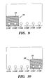
- the vacuum system 110 can be reconfigured for use with a stack 20 of right or left justified printing plates 18 by shifting the relative positions of the suction cups 114A-114F as shown in FIG. 9 (left justified) and FIG. 10 (right justified).
- the external drum platesetter 216 includes an external drum 220 having a cylindrical media support surface 222 for supporting the printing plate 18 during imaging.
- the external drum platesetter 216 further includes a scanning system 224, coupled to a movable carriage 226, for recording digital data onto the imaging surface 221 of the printing plate 18 using a single or multiple imaging beams 228.
- An example of a scanning system 224 is illustrated in FIG. 12.
- the scanning system 224 is displaced by the movable carriage 226 in a slow scan axial direction (directional arrow A) along the length of the rotating external drum 220 to expose the printing plate 18 in a line-wise manner when a single beam is used or in a section-wise manner for multiple beams.
- Other types of imaging systems may also be used in the present invention.
- FIG. 13 is illustrated the basic structure of an external drum platesetter 216 including a stack 20 of printing plates 18 (e.g., 18 1 , 18 2 , 18 3 , 18 4 ) and the vacuum system 110 of the present invention.
- the external drum platesetter 216 includes an external drum 220 having a cylindrical media support surface 222 for supporting a printing plate 18 during imaging.
- the external drum 220 is supported by a frame 272.
- a drive system 236 rotates the external drum 220 during imaging.
- a scanning system 224 carried by a movable carriage 226, travels axially along the rotating external drum 220 to record digital data onto the imaging surface of the printing plate (see, e.g., FIG. 12).
- the external drum 220 and scanning system 224 are positioned on a base 274.
- the vacuum system 110 is used to pick up a bottom edge of the top printing plate 181 from the stack 20.
- the vacuum system 110 generally comprises a plurality of suction cups 114 (e.g., 114A-114F) arranged parallel to the bottom edge of the printing plates in the stack 20.
- a system 116 for displacing the suction cups 114 toward and away from the top printing plate 18 1 , and the vacuum pump 112 for supplying a vacuum to the suction cups 114, are also illustrated in FIG. 13.
- the nip rollers 270 operate to direct the bottom (i.e., leading) edge of the top printing plate 18 1 to a plate mounting system (not shown) that is configured to mount the printing plate onto the external drum 220 of the external drum platesetter 216 for subsequent imaging.
- the top printing plate 18 1 is shown mounted to the external drum 220 in FIG. 18.
- Such a mounting system is disclosed in detail, for example, in U.S. Patent No. 6,295,929, entitled "External Drum Imaging System".
Landscapes
- Engineering & Computer Science (AREA)
- Mechanical Engineering (AREA)
- Exposure And Positioning Against Photoresist Photosensitive Materials (AREA)
- Manufacture Or Reproduction Of Printing Formes (AREA)
- Printing Plates And Materials Therefor (AREA)
Abstract
Description
- The present invention is in the field of imaging systems. More particularly, the present invention provides an apparatus and method for picking printing plates of various sizes.
- In external drum imaging systems, a movable optical carriage is commonly used to displace an image exposing or recording source in a slow scan direction while a cylindrical drum supporting recording media on an external surface thereof is rotated with respect to the image exposing source. The drum rotation causes the recording media to advance past the exposing source along a direction which is substantially perpendicular to the slow scan direction. The recording media is therefore advanced past the exposing source by the rotating drum in a fast scan direction.
- An image exposing source may include an optical system for scanning one or more exposing or recording beams. Each recording beam may be separately modulated according to a digital information signal representing data corresponding to the image to be recorded.
- The recording media to be imaged by an external drum imaging system is commonly supplied in discrete, flexible sheets and may comprise a plurality of plates, hereinafter collectively referred to as "plates" or "printing plates." Each printing plate may comprise one or more layers supported by a support substrate, which for many printing plates is a plano-graphic aluminum sheet or a polyester support. Other layers may include one or more image recording (i.e., "imageable") layers such as a photosensitive, radiation sensitive, or thermally sensitive layer, or other chemically or physically alterable layers. Printing plates are available in a wide variety of sizes, typically ranging, e.g., from 229 mm x 305 mm (9" x 12"), or smaller, to 1473 mm x 2032 mm (58" x 80"), or larger.
- A vacuum system, comprising a plurality of suction cups coupled to a vacuum source, is often employed to lift, or "pick," the top printing plate from a stack of printing plates, prior to the top printing plated being fed to the external drum of an imaging system. One cost-effective method of simultaneously distributing a vacuum to the plurality of suction cups involves the use of a single venturi vacuum pump. An example of such a
vacuum system 10 is illustrated in FIG. 1. In particular, thevacuum system 10 includes avacuum pump 12 for generating a vacuum, a plurality ofsuction cups 14A-14F,tubing 16, and identical, non-constricted (i.e., "straight-through")fittings 22 for coupling thesuction cups 14A-14F in parallel to thevacuum pump 12 viatubing 16. In this configuration, a vacuum provided by thevacuum pump 12 is simultaneously applied and distributed to each of the plurality ofsuction cups 14A-14F. - As depicted in FIG. 2, the
vacuum system 10 may be used to pick thetop printing plate 18 off of astack 20 of printing plates. When thetop printing plate 18 has a width WP greater than the effective width WSC of the plurality ofsuction cups 14A-14E, sufficient vacuum is available at each of thesuction cups 14A-14F to allow thetop printing plate 18 to be lifted from thestack 20 of printing plates. - Problems may occur, however, when the
vacuum system 10 is used to pick up aprinting plate 18 having a width WP substantially narrower than the effective width WSC of the plurality ofsuction cups 14A-14E. For example, as shown in FIG. 3, only two of the suction cups (i.e.,suction cups top printing plate 18 in a stack ofprinting plates 20. Theremaining suction cups top printing plate 18 and remain open to the atmosphere. As such, due to substantial vacuum leakage through theopen suction cups suction cups smaller printing plate 18 to be picked up and held by thevacuum system 10. - To accommodate a variety of different size printing plates, and to avoid the vacuum leakage problems detailed above, available vacuum systems often employ a manifold-type vacuum system, wherein a manifold is configured to selectively apply a vacuum to a plurality of suction cups based on the size of the printing plate to be picked up. Although quite effective, such manifold-type vacuum systems typically have a complex structure, and are expensive to implement, operate, and maintain.
- A need therefore exists for simple and inexpensive vacuum system, such as the vacuum system illustrated in FIG. 1, that is capable of picking various size printing plates while controlling the leakage flow through the suction cups that do not engage a printing plate during the picking process.
- The present invention provides an apparatus and method for picking printing plates from a stack of printing plates having the specific features set out in claims 1 and 9. Specific features for preferred embodiments of the invention are set out in the dependent claims.
- Generally, an embodiment of the present invention provides an apparatus, comprising:
- a vacuum system including a vacuum source and plurality of suction cups coupled to the vacuum source, wherein at least one of the suction cups is coupled to the vacuum source using a non-constricted fitting, and wherein at least one of the suction cups is coupled to vacuum source using a fixed orifice fitting; and a stack of printing plates; wherein the vacuum system is configured to pick a top printing plate from the stack of printing plates, and wherein each suction cup coupled to the vacuum source using a non-constricted fitting is configured to always engage the top printing plate.
-
- The present invention may also provide a method, comprising: providing a vacuum system including a vacuum source and plurality of suction cups coupled to the vacuum source; coupling at least one of the suction cups to the vacuum source using a non-constricted fitting; coupling at least one of the suction cups to the vacuum source using a fixed orifice fitting; and picking a top printing plate from a stack of printing plates using the vacuum system, wherein each suction cup coupled to the vacuum source using a non-constricted fitting is configured to always engage the top printing plate.
- The present invention may also further provide a method for picking and holding an object, comprising: providing a vacuum system including a vacuum source and plurality of suction cups coupled to the vacuum source; coupling at least one of the suction cups to the vacuum source using a non-constricted fitting; coupling at least one of the suction cups to the vacuum source using a fixed orifice fitting; and picking and holding an object using the vacuum system, wherein each suction cup coupled to the vacuum source using a non-constricted fitting always engages and holds the object, wherein zero or more of the suction cups coupled to the vacuum source using a fixed orifice fitting engage and hold the object, and wherein vacuum leakage through any suction cups that do not engage the object does not substantially affect a vacuum level within the suction cups that do engage the object.
- The features of the present invention will best be understood from a detailed description of the invention and embodiments thereof selected for the purpose of illustration and shown in the accompanying drawings in which:
- FIG. 1 illustrates a vacuum system for picking up a printing plate from a stack of printing plates in accordance with the related art;
- FIG. 2 illustrates the vacuum system of FIG. 1 picking up a printing plate that is wider than the effective width of the suction cups of the vacuum system;
- FIG. 3 illustrates the vacuum system of FIG. 1 picking up a printing plate having a width that is narrower than the effective width of the suction cups of the vacuum system;
- FIG. 4 illustrates a vacuum system for picking up a printing plate from a stack of printing plates in accordance with the present invention;
- FIG. 5 illustrated a non-constricted fitting used in the vacuum system of FIG. 4;
- FIG. 6 illustrates a fixed orifice fitting used in the vacuum system of FIG. 4;
- FIG. 7 illustrates the vacuum system of FIG. 4 picking up a printing plate having a width that is narrower than the effective width of the suction cups of the vacuum system;
- FIG. 8 illustrates the vacuum system of FIG. 4 picking up a printing plate that is wider than the effective width of the suction cups of the vacuum system;
- FIGS. 9 and 10 illustrate the use of the vacuum system of the present invention with a stack of left and right justified printing plates, respectively;
- FIG. 11 illustrates an external drum imaging system for recording images onto a printing plate;
- FIG. 12 illustrates an example of an imaging system including a movable optical carriage and scanning system, usable in the external drum imaging system of FIG. 11; and
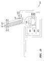
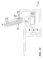
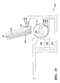
- FIGS. 13-18 illustrate the operation of a vacuum system in accordance with the present invention.
-
- The features of the present invention are illustrated in detail in the accompanying drawings, wherein like reference numerals refer to like elements throughout the drawings. Although the drawings are intended to illustrate the present invention, the drawings are not necessarily drawn to scale.
- A
vacuum system 110 for picking up a printing plate from a stack of printing plates in accordance with the present invention is illustrated in FIG. 4. In particular, thevacuum system 110 includes a vacuum source (e.g. vacuum pump) 112 for generating a vacuum, a plurality ofsuction cups 114A-114F,tubing 116, and non-constrictedfittings 122 for coupling at least one suction cup (e.g.,suction cups vacuum pump 112 viatubing 116. As shown in FIG. 5, the non-constrictedfittings 122 may comprise, for example, a tubular structure having abore 124 with a constant diameter D. Airflow direction through the non-constrictedfitting 122 is indicated bydirectional arrow 126. Other structures which do not substantially restrict the airflow therethrough may also be used in the practice of the present invention. - In addition, as illustrated in FIG. 4, unlike the related
art vacuum system 10 shown in FIG. 1, thevacuum system 110 further includes a plurality ofsuction cups vacuum pump 112 viatubing 116 usingfixed orifice fittings 128. Thus, a combination offixed orifice fittings 128 and non-constrictedfittings 122 are used in the present invention. An example of a suitablefixed orifice fitting 128 is illustrated in FIG. 6. In particular, thefixed orifice fitting 128 includes abore 130 having atubular portion 132 with a diameter D1, and a restrictedtubular portion 134 with a diameter D2 that is substantially smaller than D1. Airflow direction through thefixed orifice fitting 128 is indicated bydirectional arrow 126. Many other configurations of thefixed orifice fitting 128 are also possible. - In a preferred ambodiment, the actual diameters are as follows:
- 1. the tubular structure of the
bore 124 of the non-constrictedfittings 122 has a constant diameter D of 2.3 mm (0.089") ; - 2. the
tubular portion 132 ofbore 130 in thefixed orifice fitting 128 has a first (larger) diameter D1 of 2.4 mm (0.094") ; and, - 3. the restricted
tubular portion 134 ofbore 130 in the fixed orifice fitting 128 has a second (smaller) diameter D2 of 0.4 mm (0.015"). -
- As such, the diameters D and D1 are substantially the same, i.e. their ratio D/D1 is between 0.8 and 1.2, more preferably between 0.9 and 1.1. According to the above-mentioned embodiment, the diameter D2 is substantially smaller than the diameter D1 in the sense that the ratio D2/D1 is smaller than or equal to 0.5, preferably smaller than 0.3 or more preferably smaller than 0.2. In the above-mentioned example, the ratio D2/D1 is 0.16. The ratio D/D2 is preferably larger than or equal to 2. As long as D/D2 ≥ 2 is maintained, the diameters can vary to any sizes, although typical diameters preferably fall within the ranges between 1.3 mm and 38 mm (0.05" and 1.5") for D and D1, and between 0.2 mm and 0.8 mm (0.008" and 0.03") for D2.
- When the
vacuum system 110 is used to pick up aprinting plate 18 having a width WP substantially narrower than the effective width WSC of the plurality ofsuction cups 114A-114F, as shown, for example, in FIG. 7, only two of the suction cups (i.e.,suction cups top printing plate 18 in the stack ofprinting plates 20. The remainingsuction cups top printing plate 18 and remain open to the atmosphere. However, the restrictedtubular portion 134 of the fixedorifice fittings 128 drastically reduces vacuum leakage through theopen suction cups suction cups sized printing plate 18. As shown in FIG. 7, thesuction cups 114A-114F may be arranged in a line parallel to the bottom edge of theprinting plate 18. - The fixed
orifice fittings 128 do not effect the ability of thevacuum system 110 to lift larger size printing plates. For example, as shown in FIG. 8, all of the suction cups, includingsuction cups non-constricted fittings 122, andsuction cups orifice fittings 128, may be used to hold and pick up a largersize printing plate 18 from a stack ofprinting plates 20. In this case, negative pressure in each of thesuction cups suction cup suction cups - In the above description of the present invention, two
suction cups non-constricted fittings 122. A minimum of one suction cup having anon-constricted fitting 122 may be used in the practice of the present invention. In addition, a minimum of one suction cup having a fixed orifice fitting 128 may be used in the practice of the present invention. - The
vacuum system 110 shown in FIGS. 4, 7, and 8, is configured for use with astack 20 of center justifiedprinting plates 18. In particular, thesuction cups suction cups 114A-114F. In this way thesuction cups non-constricted fittings 122 are positioned to engage a center portion of anysize printing plate 18. In the alternative, thevacuum system 110 can be reconfigured for use with astack 20 of right or leftjustified printing plates 18 by shifting the relative positions of thesuction cups 114A-114F as shown in FIG. 9 (left justified) and FIG. 10 (right justified). - The
vacuum system 110 of the present invention is configured to pick and holdprinting plates 18 in an imaging system, such as the externaldrum imaging system 210 illustrated in FIG. 11. In general, theimaging system 210 comprises an external drum platesetter configured to record digital data onto aprinting plate 18. Although described below with regard to an external drum platesetter, thevacuum system 110 of the present invention may be used in conjunction with a wide variety of other types of external drum, internal drum, or flatbed imaging systems, including imagesetters and the like, without departing from the scope of the present invention. In addition, thevacuum system 110 of the present invention may be used to pick and hold other objects besides printing plates. - The
imaging system 210 generally includes a front end computer orworkstation 212 for the design, layout, editing, and/or processing of digital files representing pages to be printed, a raster image processor (RIP) 214 for further processing the digital pages to provide rasterized page data (e.g., rasterized digital files) for driving an image recorder, and an image recorder or engine, such as anexternal drum platesetter 216, for recording the rasterized digital files onto a printing plate or other recording media. Theexternal drum platesetter 216 records the digital data (i.e., "job") provided by theRIP 214 onto a supply of photosensitive, radiation sensitive, thermally sensitive, or other type ofsuitable printing plate 18. - A plurality of
printing plates 18 are supplied in a stack to the external drum platesetter, and are individually fed from the stack by anautoloading system 260 and mounted on anexternal drum 220. The stack ofprinting plates 18 may be located within a cassette 275 (FIG. 13). - The
external drum platesetter 216 includes anexternal drum 220 having a cylindricalmedia support surface 222 for supporting theprinting plate 18 during imaging. Theexternal drum platesetter 216 further includes ascanning system 224, coupled to amovable carriage 226, for recording digital data onto theimaging surface 221 of theprinting plate 18 using a single or multiple imaging beams 228. An example of ascanning system 224 is illustrated in FIG. 12. In particular, thescanning system 224 is displaced by themovable carriage 226 in a slow scan axial direction (directional arrow A) along the length of the rotatingexternal drum 220 to expose theprinting plate 18 in a line-wise manner when a single beam is used or in a section-wise manner for multiple beams. Other types of imaging systems may also be used in the present invention. - In FIG. 11 the
external drum 220 is rotated by adrive system 236 in a clockwise or counterclockwise direction as indicated by directional arrow B. Typically, thedrive system 236 rotates theexternal drum 220 at a rate of about 100-1000 rpm. As further illustrated in FIG. 12, thescanning system 224 typically includes asystem 230 for generating the imaging beam or beams 228. Thesystem 230 comprises a light orradiation source 232 for producing the imaging beam or beams 228 (illustrated for simplicity as a single beam), and anoptical system 234 positioned between theradiation source 232 and themedia support surface 222 for focusing the imaging beam orbeams 228 onto theprinting plate 18. It should be noted, however, that thesystem 230 described above is only one of many possible different types of scanning systems that may be used to record image data on theprinting plate 18. - In the external
drum imaging system 210 shown in FIG. 11, theleading edge 238 of theprinting plate 18 is held in position against themedia support surface 222 by a leadingedge clamping mechanism 240. Similarly, the trailingedge 242 of theprinting plate 18 is held in position against themedia support surface 222 by a trailingedge clamping mechanism 244. Both the trailingedge clamping mechanism 244 and the leadingedge clamping mechanism 240 provide a tangential friction force between theprinting plate 18 and theexternal drum 220 sufficient to resist the tendency of the edges of theprinting plate 18 to pull out of the clampingmechanisms printing plate 18 onto theexternal drum 220 may also be used. - An ironing
roller system 246 may be provided to flatten theprinting plate 18 against themedia support surface 222 of theexternal drum 220 as theexternal drum 220 rotates past the ironingroller 246 during the loading of theprinting plate 18.
Alternately, or in addition, avacuum source 245 may be used to draw a vacuum through an arrangement of ports and vacuum grooves 247 (see, e.g., FIG. 12) formed in themedia support surface 222 to hold theprinting plate 18 against themedia support surface 222. A registration system (not shown), comprising, for example, a set of registration pins or stops on theexternal drum 220, and a plate edge detection system (not shown), may be used to accurately and repeatably position and locate theprinting plate 18 on theexternal drum 220. - In FIG. 13 is illustrated the basic structure of an
external drum platesetter 216 including astack 20 of printing plates 18 (e.g., 181, 182, 183, 184) and thevacuum system 110 of the present invention. Theexternal drum platesetter 216 includes anexternal drum 220 having a cylindricalmedia support surface 222 for supporting aprinting plate 18 during imaging. Theexternal drum 220 is supported by aframe 272. Adrive system 236 rotates theexternal drum 220 during imaging. Ascanning system 224, carried by amovable carriage 226, travels axially along the rotatingexternal drum 220 to record digital data onto the imaging surface of the printing plate (see, e.g., FIG. 12). Theexternal drum 220 andscanning system 224 are positioned on abase 274. - The
stack 20 incassette 275 contains a plurality of printing plates 18 (e.g., twenty-five printing plates). Only fourprinting plates individual printing plates 18 of thestack 20. - The
vacuum system 110 is used to pick up a bottom edge of thetop printing plate 181 from thestack 20. As detailed above, thevacuum system 110 generally comprises a plurality of suction cups 114 (e.g., 114A-114F) arranged parallel to the bottom edge of the printing plates in thestack 20. Asystem 116 for displacing thesuction cups 114 toward and away from thetop printing plate 181, and thevacuum pump 112 for supplying a vacuum to thesuction cups 114, are also illustrated in FIG. 13. - An example of the operation of the
vacuum system 110 of the present invention is illustrated in FIGS. 14-18. - In FIG. 14, the
suction cups 114 are moved by the displacingsystem 116 into contact with a bottom edge of thetop printing plate 181 on thestack 20 of printing plates. A vacuum is applied to thesuction cups 114 by thevacuum pump 112, thereby securely coupling the bottom edge of thetop printing plate 181 to thedisplacing system 116. - In FIG. 15, the bottom edge of the
top printing plate 181 is peeled away from thestack 20 of printing plates by the displacingsystem 116. At this point, a printing plate supporting andfeeding system 300 is actuated to peel thetop printing plate 181 away from, and off of, the next printing plated 182 of thestack 20. The printing plate supporting andfeeding system 300 continues to operate (FIG. 16) until thetop printing plate 181 is fully peeled off of the stack 20 (FIG. 17). With thesuction cups 114 still attached by vacuum to thetop printing plate 181, the displacing system 116 (and attached top printing plate 181) may be shifted downward to position the edge of thetop printing plate 181 at or within a pair of niprollers 270. The niprollers 270 operate to direct the bottom (i.e., leading) edge of thetop printing plate 181 to a plate mounting system (not shown) that is configured to mount the printing plate onto theexternal drum 220 of theexternal drum platesetter 216 for subsequent imaging. Thetop printing plate 181 is shown mounted to theexternal drum 220 in FIG. 18. Such a mounting system is disclosed in detail, for example, in U.S. Patent No. 6,295,929, entitled "External Drum Imaging System". - The foregoing description of the present invention has been presented for purposes of illustration and description. It is not intended to be exhaustive or to limit the invention to the precise form disclosed, and many modifications and variations are possible in light of the above teaching. Such modifications and variations that may be apparent to a person skilled in the art may be included within the scope of this invention.
Claims (10)
- An apparatus, comprising:a vacuum system (110) including a vacuum source (112) and plurality of suction cups (114A-114F) coupled to the vacuum source (112), wherein at least one of the suction cups (114C) is coupled to the vacuum source (112) using a non-constricted fitting (122), and wherein at least one of the suction cups (114A) is coupled to the vacuum source (112) using a fixed orifice fitting (128); anda stack (20) of printing plates (18);wherein the vacuum system (110) is configured to pick a top printing plate (181) from the stack (20) of printing plates (18), and wherein each suction cup (114C) coupled to the vacuum source (112) using a non-constricted fitting (122) is configured to always engage the top printing plate (181).
- The apparatus of claim 1, wherein at least two of the suction cups (114C, 114D) are coupled to the vacuum source (112) using the non-constricted fitting (122), and wherein the remaining suction cups (114A-B,114E-F) are coupled to the vacuum source (112) using the fixed orifice fittings (128).
- The apparatus of claim 1 or 2, wherein, if the printing plates (18) in the stack (20) of printing plates (18) are center, left or right justified with respect to each other, then the at least one suction cup (114C) coupled to the vacuum source (112) using a non-constricted fitting (122) is center, left or right justified respectively with respect to the plurality of suction cups (114A-F).
- The apparatus according to any one of the previous claims, wherein each non-constricted fitting (122) has a bore (124) with a constant diameter (D).
- The apparatus according to any one of the previous claims, wherein each fixed orifice fitting (128) comprises a first bore (130) having a first diameter (D1) and a second bore (134) having a second diameter (D2), and wherein the second diameter (D2) is substantially smaller than the first diameter (D1).
- The apparatus according to any one of the previous claims, wherein the stack (20) of printing plates (18) is located within a cassette (275).
- The apparatus according to any one of the previous claims, further comprising:a media support surface (222);a mounting system (240, 244) for mounting the top printing plate (181), picked of the stack (20) of printing plates (18) by the vacuum system (112), on the media support surface (222); anda scanning system (224) for imaging data onto the top printing plate (181).
- The apparatus according to any one of the previous claims, wherein the media support surface (222) comprises an external drum (220).
- A method, comprising:providing a vacuum system (110) including a vacuum source (112) and plurality of suction cups (114A-F) coupled to the vacuum source (112);coupling at least one of the suction cups (114C) to the vacuum source (112) using a non-constricted fitting (122);coupling at least one of the suction cups (114A) to the vacuum source (112) using a fixed orifice fitting (128); andpicking a top printing plate (181) from a stack (20) of printing plates (18) using the vacuum system (110), wherein each suction cup (114C) coupled to the vacuum source (112) using a non-constricted fitting (122) is configured to always engage the top printing plate (181).
- The method of claim 9, wherein a width (Wp) of each printing plate (18) in the stack (20) of printing plates is smaller than an effective width (WSC) of the suction cups (114A-F).
Applications Claiming Priority (2)
| Application Number | Priority Date | Filing Date | Title |
|---|---|---|---|
| US10/045,551 US6571709B1 (en) | 2002-01-10 | 2002-01-10 | Apparatus and method for picking printing plates of various sizes |
| US45551 | 2002-01-10 |
Publications (2)
| Publication Number | Publication Date |
|---|---|
| EP1327593A1 true EP1327593A1 (en) | 2003-07-16 |
| EP1327593B1 EP1327593B1 (en) | 2006-04-05 |
Family
ID=21938561
Family Applications (1)
| Application Number | Title | Priority Date | Filing Date |
|---|---|---|---|
| EP03100039A Expired - Lifetime EP1327593B1 (en) | 2002-01-10 | 2003-01-10 | Apparatus and method for picking printing plates of various sizes |
Country Status (4)
| Country | Link |
|---|---|
| US (1) | US6571709B1 (en) |
| EP (1) | EP1327593B1 (en) |
| JP (1) | JP2003211864A (en) |
| DE (1) | DE60304373T2 (en) |
Families Citing this family (6)
| Publication number | Priority date | Publication date | Assignee | Title |
|---|---|---|---|---|
| DE10104078A1 (en) * | 2001-01-29 | 2002-08-01 | Heidelberger Druckmasch Ag | Process and device for separating printing plates |
| JP2006176287A (en) * | 2004-12-22 | 2006-07-06 | Fuji Photo Film Co Ltd | Automatic supply device of photosensitive printing plate |
| US8998892B2 (en) | 2007-12-21 | 2015-04-07 | Atricure, Inc. | Ablation device with cooled electrodes and methods of use |
| US8353907B2 (en) | 2007-12-21 | 2013-01-15 | Atricure, Inc. | Ablation device with internally cooled electrodes |
| EP2138437A1 (en) * | 2008-06-27 | 2009-12-30 | Kba-Giori S.A. | Inspection system for inspecting the quality of printed sheets |
| CN105745081B (en) | 2013-07-28 | 2019-10-25 | 惠普工业印刷有限公司 | Medium support device |
Citations (2)
| Publication number | Priority date | Publication date | Assignee | Title |
|---|---|---|---|---|
| US3617048A (en) * | 1970-04-17 | 1971-11-02 | Eastman Kodak Co | Vacuum paper feeder |
| US6155795A (en) * | 1998-03-20 | 2000-12-05 | J. Schmalz Gmbh | Ejector |
Family Cites Families (18)
| Publication number | Priority date | Publication date | Assignee | Title |
|---|---|---|---|---|
| US715905A (en) | 1902-02-21 | 1902-12-16 | Abbot Augustus Low | Paper-lifting mechanism. |
| US2198765A (en) | 1938-08-05 | 1940-04-30 | Merritt Engineering & Sales Co | Vacuum cup and vacuum cup system |
| US2680994A (en) | 1951-10-22 | 1954-06-15 | Boeing Co | Suction holding device |
| US3307819A (en) | 1965-04-12 | 1967-03-07 | Cocito Joe Michael | Disc valve for vacuum board |
| CA942346A (en) | 1970-03-13 | 1974-02-19 | Federico Capetti | Suction device for picking up sheets |
| US3907268A (en) | 1974-03-29 | 1975-09-23 | Thomas F Hale | Valve means for vacuum holding device |
| US3991997A (en) * | 1974-12-30 | 1976-11-16 | Barber Walter W | Paper feed mechanism for offset printer |
| US4221356A (en) | 1978-11-09 | 1980-09-09 | Fortune William S | Vacuum operated holding fixture |
| US4744297A (en) | 1985-09-17 | 1988-05-17 | The Ward Machinery Company | Mounting printing plates |
| JPS62180831A (en) * | 1986-02-04 | 1987-08-08 | Sharp Corp | Attracting device for sheet material |
| DE3629968A1 (en) * | 1986-09-03 | 1988-03-10 | Messerschmitt Boelkow Blohm | DEVICE FOR RECEIVING AND DEPOSITING CUTS |
| US4787662A (en) | 1987-08-28 | 1988-11-29 | Hewlett-Packard Company | Vacuum driven gripping tool |
| DE3926121A1 (en) | 1989-08-08 | 1991-02-14 | Focke & Co | DEVICE FOR PROMOTING LOCATIONS FROM A MULTIPLE NUMBER OF ITEMS |
| US5177857A (en) | 1990-05-17 | 1993-01-12 | Fsk Inc. | Method for holding an object to a surface using valve controlled vacuum force |
| JPH04161336A (en) * | 1990-10-25 | 1992-06-04 | Sumitomo Heavy Ind Ltd | Adsorber of paper feed cylinder in printing machine |
| US5960821A (en) | 1996-11-12 | 1999-10-05 | Johnson; Edwin Lee | Flow sensor device and associated vacuum holding system |
| JP2001113849A (en) * | 1999-08-11 | 2001-04-24 | Toray Ind Inc | Imaging medium, positioning method thereof, imaging method, imaging apparatus and printing apparatus |
| JP2001199574A (en) * | 2000-01-20 | 2001-07-24 | Fuji Photo Film Co Ltd | Structure of sheet material suction part |
-
2002
- 2002-01-10 US US10/045,551 patent/US6571709B1/en not_active Expired - Fee Related
- 2002-12-24 JP JP2002371693A patent/JP2003211864A/en active Pending
-
2003
- 2003-01-10 EP EP03100039A patent/EP1327593B1/en not_active Expired - Lifetime
- 2003-01-10 DE DE60304373T patent/DE60304373T2/en not_active Expired - Lifetime
Patent Citations (2)
| Publication number | Priority date | Publication date | Assignee | Title |
|---|---|---|---|---|
| US3617048A (en) * | 1970-04-17 | 1971-11-02 | Eastman Kodak Co | Vacuum paper feeder |
| US6155795A (en) * | 1998-03-20 | 2000-12-05 | J. Schmalz Gmbh | Ejector |
Also Published As
| Publication number | Publication date |
|---|---|
| EP1327593B1 (en) | 2006-04-05 |
| DE60304373D1 (en) | 2006-05-18 |
| JP2003211864A (en) | 2003-07-30 |
| US6571709B1 (en) | 2003-06-03 |
| DE60304373T2 (en) | 2007-01-11 |
Similar Documents
| Publication | Publication Date | Title |
|---|---|---|
| US6688591B2 (en) | Apparatus and method for removing slip sheets | |
| US6675712B2 (en) | Apparatus and method for picking a single printing plate from a stack of printing plates | |
| US6571709B1 (en) | Apparatus and method for picking printing plates of various sizes | |
| US5889547A (en) | Registration detection apparatus for imaging systems | |
| US6097475A (en) | Method and apparatus for orienting a recording media sheet on a support surface | |
| US6233038B1 (en) | Imaging system with integral punch mechanism | |
| US6254091B1 (en) | Variable cross-section vacuum grooves in an imaging system | |
| EP1471018A2 (en) | Apparatus for delivering printing plates to an external drum imaging system | |
| EP1408680A2 (en) | Media clamping apparatus and method for an external drum imaging system. | |
| US6772691B2 (en) | System and method for registering media in an imaging system | |
| US6880462B2 (en) | Apparatus and method for peeling a printing plate from a stack of plates | |
| US7262878B2 (en) | System and method for calibrating an imaging system during imaging | |
| JP2001113849A (en) | Imaging medium, positioning method thereof, imaging method, imaging apparatus and printing apparatus | |
| EP1388416B1 (en) | Method and system for simultaneous loading and unloading of substrates in platesetter | |
| US6739257B1 (en) | Media clamping apparatus for an external drum imaging system | |
| US6994027B1 (en) | Device and method to prevent movement of a printing plate during clamping | |
| US6779450B1 (en) | Thin-wall drum for external drum imaging system | |
| EP1486816A1 (en) | Method and apparatus for reducing contamination in a grating light valve imaging system. | |
| US20040041990A1 (en) | System and method for using flexographic media in an imaging system | |
| EP1401187A2 (en) | Method and apparatus for incrementally displacing recording media in an imaging system. |
Legal Events
| Date | Code | Title | Description |
|---|---|---|---|
| PUAI | Public reference made under article 153(3) epc to a published international application that has entered the european phase |
Free format text: ORIGINAL CODE: 0009012 |
|
| AK | Designated contracting states |
Designated state(s): AT BE BG CH CY CZ DE DK EE ES FI FR GB GR HU IE IT LI LU MC NL PT SE SI SK TR |
|
| AX | Request for extension of the european patent |
Extension state: AL LT LV MK RO |
|
| 17P | Request for examination filed |
Effective date: 20040116 |
|
| AKX | Designation fees paid |
Designated state(s): DE FR GB |
|
| 17Q | First examination report despatched |
Effective date: 20040917 |
|
| GRAP | Despatch of communication of intention to grant a patent |
Free format text: ORIGINAL CODE: EPIDOSNIGR1 |
|
| GRAS | Grant fee paid |
Free format text: ORIGINAL CODE: EPIDOSNIGR3 |
|
| GRAA | (expected) grant |
Free format text: ORIGINAL CODE: 0009210 |
|
| AK | Designated contracting states |
Kind code of ref document: B1 Designated state(s): DE FR GB |
|
| REG | Reference to a national code |
Ref country code: GB Ref legal event code: FG4D |
|
| REF | Corresponds to: |
Ref document number: 60304373 Country of ref document: DE Date of ref document: 20060518 Kind code of ref document: P |
|
| ET | Fr: translation filed | ||
| PLBE | No opposition filed within time limit |
Free format text: ORIGINAL CODE: 0009261 |
|
| STAA | Information on the status of an ep patent application or granted ep patent |
Free format text: STATUS: NO OPPOSITION FILED WITHIN TIME LIMIT |
|
| 26N | No opposition filed |
Effective date: 20070108 |
|
| PGFP | Annual fee paid to national office [announced via postgrant information from national office to epo] |
Ref country code: FR Payment date: 20101221 Year of fee payment: 9 |
|
| PGFP | Annual fee paid to national office [announced via postgrant information from national office to epo] |
Ref country code: GB Payment date: 20101216 Year of fee payment: 9 |
|
| PGFP | Annual fee paid to national office [announced via postgrant information from national office to epo] |
Ref country code: DE Payment date: 20101215 Year of fee payment: 9 |
|
| GBPC | Gb: european patent ceased through non-payment of renewal fee |
Effective date: 20120110 |
|
| REG | Reference to a national code |
Ref country code: FR Ref legal event code: ST Effective date: 20120928 |
|
| PG25 | Lapsed in a contracting state [announced via postgrant information from national office to epo] |
Ref country code: GB Free format text: LAPSE BECAUSE OF NON-PAYMENT OF DUE FEES Effective date: 20120110 Ref country code: DE Free format text: LAPSE BECAUSE OF NON-PAYMENT OF DUE FEES Effective date: 20120801 |
|
| REG | Reference to a national code |
Ref country code: DE Ref legal event code: R119 Ref document number: 60304373 Country of ref document: DE Effective date: 20120801 |
|
| PG25 | Lapsed in a contracting state [announced via postgrant information from national office to epo] |
Ref country code: FR Free format text: LAPSE BECAUSE OF NON-PAYMENT OF DUE FEES Effective date: 20120131 |