EP1327557A1 - Headrest for automobile seats - Google Patents
Headrest for automobile seats Download PDFInfo
- Publication number
- EP1327557A1 EP1327557A1 EP02380257A EP02380257A EP1327557A1 EP 1327557 A1 EP1327557 A1 EP 1327557A1 EP 02380257 A EP02380257 A EP 02380257A EP 02380257 A EP02380257 A EP 02380257A EP 1327557 A1 EP1327557 A1 EP 1327557A1
- Authority
- EP
- European Patent Office
- Prior art keywords
- front body
- shaft
- connecting rod
- swivelling
- headrest
- Prior art date
- Legal status (The legal status is an assumption and is not a legal conclusion. Google has not performed a legal analysis and makes no representation as to the accuracy of the status listed.)
- Granted
Links
- 238000000926 separation method Methods 0.000 claims abstract description 21
- XEEYBQQBJWHFJM-UHFFFAOYSA-N Iron Chemical group [Fe] XEEYBQQBJWHFJM-UHFFFAOYSA-N 0.000 claims description 20
- 229910052742 iron Inorganic materials 0.000 claims description 10
- 230000000694 effects Effects 0.000 claims description 2
- 230000004913 activation Effects 0.000 description 12
- 230000009471 action Effects 0.000 description 6
- 238000006073 displacement reaction Methods 0.000 description 5
- 230000007246 mechanism Effects 0.000 description 5
- 238000010276 construction Methods 0.000 description 3
- 230000000717 retained effect Effects 0.000 description 3
- 238000000605 extraction Methods 0.000 description 2
- 239000002184 metal Substances 0.000 description 2
- 229910052751 metal Inorganic materials 0.000 description 2
- 230000004044 response Effects 0.000 description 2
- 230000002441 reversible effect Effects 0.000 description 2
- 238000010521 absorption reaction Methods 0.000 description 1
- 230000003213 activating effect Effects 0.000 description 1
- 239000006260 foam Substances 0.000 description 1
- 230000001105 regulatory effect Effects 0.000 description 1
Images



Classifications
-
- B—PERFORMING OPERATIONS; TRANSPORTING
- B60—VEHICLES IN GENERAL
- B60N—SEATS SPECIALLY ADAPTED FOR VEHICLES; VEHICLE PASSENGER ACCOMMODATION NOT OTHERWISE PROVIDED FOR
- B60N2/00—Seats specially adapted for vehicles; Arrangement or mounting of seats in vehicles
- B60N2/80—Head-rests
- B60N2/806—Head-rests movable or adjustable
- B60N2/838—Tiltable
- B60N2/853—Tiltable characterised by their adjusting mechanisms, e.g. electric motors
-
- B—PERFORMING OPERATIONS; TRANSPORTING
- B60—VEHICLES IN GENERAL
- B60N—SEATS SPECIALLY ADAPTED FOR VEHICLES; VEHICLE PASSENGER ACCOMMODATION NOT OTHERWISE PROVIDED FOR
- B60N2/00—Seats specially adapted for vehicles; Arrangement or mounting of seats in vehicles
- B60N2/80—Head-rests
- B60N2/806—Head-rests movable or adjustable
- B60N2/838—Tiltable
- B60N2/841—Tiltable characterised by their locking devices
- B60N2/85—Tiltable characterised by their locking devices with continuous positioning
-
- B—PERFORMING OPERATIONS; TRANSPORTING
- B60—VEHICLES IN GENERAL
- B60N—SEATS SPECIALLY ADAPTED FOR VEHICLES; VEHICLE PASSENGER ACCOMMODATION NOT OTHERWISE PROVIDED FOR
- B60N2/00—Seats specially adapted for vehicles; Arrangement or mounting of seats in vehicles
- B60N2/80—Head-rests
- B60N2/888—Head-rests with arrangements for protecting against abnormal g-forces, e.g. by displacement of the head-rest
Definitions
- the present invention relates to a headrest for automobile seats applicable to both front and back seats, of the type having two parallel columns mounted on the back of the seat which support a padded element intended to support the head.
- the padded element In conventional headrests of the above described type, the padded element consists of a single piece which can be regulated in height and inclination to adapt to various user heights and be placed more or less near the user's head. However, once a position has been selected the padded element determines a passive element that will act as a support for the head when the head moves from the normal driving position to a rear position in which it comes in contact with the padded element.
- the padded element consists of two parts, a front part and a rear part, at least the front part being displaceable from an inactive position where it is set against the rear part to define the general configuration of the headrest, and a forward position where it is separated from the rear part and moved towards the head of the occupant of the seat.
- This displacement of the front part is achieved by a mechanism which is activated when the vehicle suffers a rear collision.
- the headrest acts as an active element in the event of a rear collision, the front part of the headrest moving towards the user's head, approaching it so that the distance travelled by the head until reaching the headrest is reduced.
- Headrests of the above-described type have been described, for example, in EP-A-1122122, DE-A-3900495 and DE-A-19757533.
- the mechanism in charge of moving the front part of the headrest relies on the displacement of an inertial mass, on the action of a spring or on the action of a hydraulic system. All of these systems have the problem of having a relatively slow response, which reduces the efficiency of the headrest, as well as including relatively complex mechanisms.
- the object of the present invention is a headrest of the above-described type, wherein the padded element consists of two parts, a mobile front part and an upper fixed part, by which a fast response of the mobile part is achieved in the event that the automobile suffers a rear collision.
- the padded element of the headrest consists of a fixed rear body and a swivelling front body.
- the fixed body is mounted directly on the parallel columns, while the swivelling body is mounted on a horizontal shaft and can swivel between a position of maximum proximity and one of maximum separation from the fixed rear body, being constantly pushed towards the position of maximum separation by one or more springs.
- the horizontal shaft is supported by a parallel crossbar fixed between the parallel columns by an intermediate connecting rod, on which is mounted an electromagnet in charge of releasing a hook that retains the swivelling body in its position of maximum approach to the fixed rear body, against the action of the aforementioned springs.
- the aforementioned electromagnet will be activated when the vehicle receives a rear collision or impact, locking in place the hook that retains the swivelling body, which is thus free to move towards the position of maximum separation by the action of the aforementioned spring or springs.
- the front swivelling body includes a frame consisting of two plates mounted on the same swivelling shaft, a larger outer plate that will support the corresponding padded element and a smaller inner plate that rests on the larger plate.
- the smaller plate conforms a tubular shaft, inside which runs the swivelling shaft.
- the connecting rod between this shaft and the crossbar of the parallel columns is mounted on the tubular shaft of the smaller plate.
- On the same tubular shaft are mounted two torsion springs connected on one end to the smaller plate and on the other end to the connecting rod, in charge of pushing the smaller plate against the larger one and both plates, with the padded element, towards the position of maximum separation from the rear body.
- the smaller plate is also provided with a tooth which is engaged by the hook actuated by the electromagnet.
- the two parallel columns will be connected at their upper end by an intermediate segment, defining an inverted-U shape between whose side arms runs the crossbar connected to the swivelling shaft.
- the fixed rear body of the padded element is mounted on the top segment of the U-shape. Said body, as well as the plates that form part of the front swivelling body, will be covered in foam and suitably upholstered, the assembly complying with corresponding standards for energy absorption and headrest efficiency.
- the means for retaining the front body in its position of minimum separation from the fixed rear body consist of a magnet attached to the connecting rod and an iron-bearing core, which is part of the mobile front body and is located opposite said magnet.
- the iron-bearing core is surrounded by a coil which when activated creates a magnetic field of equal magnitude and opposite sign to that of the magnet, in order to counteract the effect of said magnet and release the mobile front body.
- the aforementioned magnet which forms part of the means for retaining the front body in its position of minimum separation from the fixed rear body has a cup-shaped configuration inside which can be coupled the iron-bearing core when the mobile front body of the headrest is in its position of minimum separation from the fixed rear body.
- the iron-bearing core is mounted on the smaller plate and can adopt a conical configuration around which is wound the aforementioned coil.
- the means for retaining the front body in its position of minimum separation from the fixed rear body consist of the connecting rod itself, which links the swivelling shaft of said front body with the crossbar of the frame.
- the connecting rod tightly embraces both the swivelling shaft and the crossbar, so that the friction between these prevents the free swivelling of the front body.
- the driving means of the mobile front body consist of a pyrotechnic piston and a plunger that moves axially inside the chamber.
- the casing or chamber houses the pyrotechnic component and is mounted on the connecting rod by a hinge shaft parallel to the swivelling shaft of the front body.
- the plunger its external end rests on an opposing arched guide of the front body, being free to slide along said guide.
- Said guide can be located on the plate which forms the frame of the front body.
- the guide can consist of a groove crossing the plate longitudinally, on which the end of the plunger rests and is free to slide.
- the plunger of the pyrotechnic piston can be provided on its free end with a freely-rotating spherical body conforming a bearing by which it rests on the guide of the swivelling front body, thereby facilitating its displacement or motion in said guide.
- the pyrotechnic piston can also be hinged between the connecting rod and the plate by parallel shafts.
- the pyrotechnic component of the piston can be activated when the vehicle suffers a collision or impact from the rear, causing the displacement of the piston plunger towards the position of maximum extraction from the casing or chamber, this action forcing the swivelling front body to move to the position farthest from the fixed rear body.
- the pyrotechnic piston allows adjusting the headrest inclination to place the mobile element in the most suitable position according to the characteristics or preferences of the user, and is also in charge of setting the mobile element in its position farthest from the fixed element by activating the pyrotechnic component in the event of a rear collision or impact.
- the headrest of the invention includes a frame consisting of two parallel columns, labelled with the number 1, which are joined on their upper end by an intermediate segment 2, determining an inverted-U shape. Located between the parallel segments or columns 1 is a crossbar 3. As is usual, the parallel segments or columns 1 are inserted in the back of the seat through top orifices made in said seat.
- the padded element of the headrest which according to the invention consists of a fixed rear body labelled with the number 4, and a swivelling front body 5.
- the fixed rear body 4 is mounted on the frame formed by the columns 1 and the upper segment 2, while the swivelling front body is mounted on a shaft 6 that is supported by the crossbar 3 of the frame by means of an intermediate connecting rod 7, which tightly embraces the crossbar 3 so that the body cannot rotate freely about the crossbar, thus requiring an effort to adjust manually the position of the front body 5 (by adjusting the headrest shaft).
- the front body 5 includes a frame consisting of two plates, an external larger plate labelled with the number 8, which supports the padded body 5, and a smaller inner plate labelled with the number 9, which rests on the larger plate 8.
- the smaller plate 9 conforms a tubular shaft 10 through which passes the swivelling shaft 6.
- the larger plate 8 conforms tubular passages 11 on either side of the tubular shaft 10 and aligned with it, for passage of the swivelling shaft 6. In this way the two plates 8 and 9 are mounted on the same swivelling shaft 6.
- the connecting rod 7 is mounted on the intermediate segment of the tubular shaft 10, embracing said tubular shaft.
- On either side of the connecting rod 7 and on the same tubular shaft 10 are mounted two torsion springs 12 connected on one end to the smaller plate 9 and on the other end to the connecting rod 7, so that they constantly push the plate 9 towards the plate 8, and the assembly of the two plates and the padded element 5 mounted on them towards a position of maximum separation with respect to the fixed rear body 9 of the headrest.
- the connecting rod 7 defines a platform in which an electromagnet 13 is mounted, which as can be seen best in figure 2 is in charge of actuating a hook 14 capable of acting on a tooth 15 which forms part of the smaller plate 9 in order to retain the latter, together with the larger plate 8, in a position of maximum proximity to the rear body 4.
- the plates 8 and 9, together with the padded element 5, are constantly pushed towards the position of maximum separation from the rear body 4 by the torsion springs 12. In the position shown in figure 2, the plates 8 and 9 and the padded body 5 are in their position of greatest proximity to the rear body 4, as the smaller plate 9 is retained by the hook 14.
- One alternative can consist in that after the electromagnet 13 has been activated and the body 5 has been displaced towards the user's head, said body is fixed in the position of maximum separation from the fixed body 4. At the moment in which the head meets the swivelling body 5 the entire headrest structure, together with the back of the seat, will absorb the energy carried by the head. After activation it will be necessary to use a special tool or to take the automobile to a specialised garage in order to rearm the headrest and leave it ready for a new activation. Despite this, the system would still be reversible, as no damaged parts have to be replaced.
- the connecting rod 7 can be a single piece or, as shown in figure 3, comprise two parts 7a and 7b joined by any system, such as screws 16.
- the electromagnet 13, not shown, will be mounted on the segment 7b.
- the swivelling front body is mounted on the shaft 6, which is supported by the crossbar 3 of the frame by means of the intermediate connecting rod 7, which tightly embraces the crossbar 3 so that said connecting rod cannot revolve about the crossbar, requiring an effort to carry out the manual adjustment of the position of the front body 5 (adjusting the inclination of the headrest).
- a cup-shaped electromagnet 17 Mounted on said connecting rod 7 by means of a small support 13' is a cup-shaped electromagnet 17, in which fits a metal cone 18 mounted above the smaller plate 9 and surrounded by an activation coil 19. This magnet is in charge of retaining the smaller plate 9 in its position of maximum proximity to the fixed rear body by the action of its magnetic field.
- the head At the moment in which the head meets the body 5, because of its inertia in a direction opposite to the direction of travel it will push against the body 5 and the plates 8 and 9, again torsioning the springs 12 to their initial position in which the metal cone 18 is inserted in the magnet 17 and will again be retained by its magnetic field, thereby leaving the headrest ready to be activated as many times as may be necessary.
- One alternative can consist in that after the magnet has been neutralised and the body 5 has been displaced towards the user's head, said body is fixed in the position of maximum separation from the fixed body 4. When the head meets the swivelling body 5 the entire headrest structure, as well as the seat back, will absorb the energy carried by the head.
- the front body 5 includes a frame comprised of a single plate 8 which supports the padded body 5.
- This plate conforms tubular passages 9 for passage of the swivelling shaft 6; said plate can be fixed to the shaft so that it cannot revolve about it, or be mounted tightly on said shaft.
- the plate 8 is mounted on the swivelling shaft 6 so that a certain effort is required to make it swivel about said shaft.
- a telescoping pyrotechnic piston 20 mounted by means of a support 13" which is joined to said connecting rod.
- the pyrotechnic piston 20 consists of a casing or chamber 21 where the pyrotechnic component is housed and a plunger 22 axially displaceable in the chamber 21. Assembly of the piston in the support 13" is achieved by the chamber 21, by means of a hinged shaft 23 parallel to the shaft 6.
- the plunger 22 can end at its external end in a freely revolving sphere 24.
- the plate 8 is provided on its surface opposite the pyrotechnic piston 20 with a vertical groove 25 that defines a guide on which rests the free end of the plunger 22, on the sphere 24 that determines a bearing.
- the processor will send the corresponding signal to the pyrotechnic component housed in the chamber 21 of the piston 20, causing its ignition and thereby the displacement of the plunger 22 towards the outside of the chamber 21, until reaching the position of maximum extraction.
- the plunger 22 pushes the plate 8, the sphere 24 moving along the groove or guide 25, thereby carrying with it the front padded body 5 quickly until it reaches its farthest position to the fixed body 4 and, consecuently its nearest position to the user's head, with this position being fixed.
- the entire headrest structure together with the seat back will absorb the energy carried by the head.
- the pyrotechnic piston can be jointed between the plate 8 and the support 13' of the connecting rod 7.
- the plunger 22 of the piston 20 can be housed in an undeformable sheath or bushing 26, which would be hinged to the plate 8 by a shaft 27, parallel to the shaft 23 hinging the piston to the support 13', which crosses lugs 28 joined to the plate 8.
Landscapes
- Engineering & Computer Science (AREA)
- Aviation & Aerospace Engineering (AREA)
- Transportation (AREA)
- Mechanical Engineering (AREA)
- Seats For Vehicles (AREA)
- Fittings On The Vehicle Exterior For Carrying Loads, And Devices For Holding Or Mounting Articles (AREA)
- Chair Legs, Seat Parts, And Backrests (AREA)
- Rear-View Mirror Devices That Are Mounted On The Exterior Of The Vehicle (AREA)
Abstract
Description
- The present invention relates to a headrest for automobile seats applicable to both front and back seats, of the type having two parallel columns mounted on the back of the seat which support a padded element intended to support the head.
- In conventional headrests of the above described type, the padded element consists of a single piece which can be regulated in height and inclination to adapt to various user heights and be placed more or less near the user's head. However, once a position has been selected the padded element determines a passive element that will act as a support for the head when the head moves from the normal driving position to a rear position in which it comes in contact with the padded element.
- This means that if the vehicle suffers a collision from the rear, in order for the headrest to act as a support for the seat occupant's head it is necessary for the head to move backwards until reaching said padded element. This reduces the efficiency of the headrest.
- In order to prevent this problem headrests have been developed wherein the padded element consists of two parts, a front part and a rear part, at least the front part being displaceable from an inactive position where it is set against the rear part to define the general configuration of the headrest, and a forward position where it is separated from the rear part and moved towards the head of the occupant of the seat. This displacement of the front part is achieved by a mechanism which is activated when the vehicle suffers a rear collision.
- With this construction, the headrest acts as an active element in the event of a rear collision, the front part of the headrest moving towards the user's head, approaching it so that the distance travelled by the head until reaching the headrest is reduced.
- Headrests of the above-described type have been described, for example, in EP-A-1122122, DE-A-3900495 and DE-A-19757533. In all of these cases the mechanism in charge of moving the front part of the headrest relies on the displacement of an inertial mass, on the action of a spring or on the action of a hydraulic system. All of these systems have the problem of having a relatively slow response, which reduces the efficiency of the headrest, as well as including relatively complex mechanisms.
- The object of the present invention is a headrest of the above-described type, wherein the padded element consists of two parts, a mobile front part and an upper fixed part, by which a fast response of the mobile part is achieved in the event that the automobile suffers a rear collision.
- According to the present invention, the padded element of the headrest consists of a fixed rear body and a swivelling front body. The fixed body is mounted directly on the parallel columns, while the swivelling body is mounted on a horizontal shaft and can swivel between a position of maximum proximity and one of maximum separation from the fixed rear body, being constantly pushed towards the position of maximum separation by one or more springs. The horizontal shaft is supported by a parallel crossbar fixed between the parallel columns by an intermediate connecting rod, on which is mounted an electromagnet in charge of releasing a hook that retains the swivelling body in its position of maximum approach to the fixed rear body, against the action of the aforementioned springs.
- The aforementioned electromagnet will be activated when the vehicle receives a rear collision or impact, locking in place the hook that retains the swivelling body, which is thus free to move towards the position of maximum separation by the action of the aforementioned spring or springs.
- The front swivelling body includes a frame consisting of two plates mounted on the same swivelling shaft, a larger outer plate that will support the corresponding padded element and a smaller inner plate that rests on the larger plate. The smaller plate conforms a tubular shaft, inside which runs the swivelling shaft. The connecting rod between this shaft and the crossbar of the parallel columns is mounted on the tubular shaft of the smaller plate. On the same tubular shaft are mounted two torsion springs connected on one end to the smaller plate and on the other end to the connecting rod, in charge of pushing the smaller plate against the larger one and both plates, with the padded element, towards the position of maximum separation from the rear body. The smaller plate is also provided with a tooth which is engaged by the hook actuated by the electromagnet.
- The two parallel columns will be connected at their upper end by an intermediate segment, defining an inverted-U shape between whose side arms runs the crossbar connected to the swivelling shaft.
- The fixed rear body of the padded element is mounted on the top segment of the U-shape. Said body, as well as the plates that form part of the front swivelling body, will be covered in foam and suitably upholstered, the assembly complying with corresponding standards for energy absorption and headrest efficiency.
- With the above-described construction, when a collision from the rear takes place this will be detected by sensors which will send a signal to the vehicle's electronic processor, which filters the signal and according to certain collision algorithms programmed in it will decide whether or not to activate the headrest electromagnet in order to release its mobile front body.
- According to a first example of embodiment, the means for retaining the front body in its position of minimum separation from the fixed rear body consist of a magnet attached to the connecting rod and an iron-bearing core, which is part of the mobile front body and is located opposite said magnet. The iron-bearing core is surrounded by a coil which when activated creates a magnetic field of equal magnitude and opposite sign to that of the magnet, in order to counteract the effect of said magnet and release the mobile front body.
- The aforementioned magnet which forms part of the means for retaining the front body in its position of minimum separation from the fixed rear body has a cup-shaped configuration inside which can be coupled the iron-bearing core when the mobile front body of the headrest is in its position of minimum separation from the fixed rear body.
- The iron-bearing core is mounted on the smaller plate and can adopt a conical configuration around which is wound the aforementioned coil.
- According to a second example of embodiment, the means for retaining the front body in its position of minimum separation from the fixed rear body consist of the connecting rod itself, which links the swivelling shaft of said front body with the crossbar of the frame. For this purpose, the connecting rod tightly embraces both the swivelling shaft and the crossbar, so that the friction between these prevents the free swivelling of the front body. This system allows retaining the mobile front body of the padded element in the selected position.
- On its part, the driving means of the mobile front body consist of a pyrotechnic piston and a plunger that moves axially inside the chamber. The casing or chamber houses the pyrotechnic component and is mounted on the connecting rod by a hinge shaft parallel to the swivelling shaft of the front body. As regards the plunger, its external end rests on an opposing arched guide of the front body, being free to slide along said guide.
- Said guide can be located on the plate which forms the frame of the front body. The guide can consist of a groove crossing the plate longitudinally, on which the end of the plunger rests and is free to slide.
- The plunger of the pyrotechnic piston can be provided on its free end with a freely-rotating spherical body conforming a bearing by which it rests on the guide of the swivelling front body, thereby facilitating its displacement or motion in said guide. The pyrotechnic piston can also be hinged between the connecting rod and the plate by parallel shafts.
- The pyrotechnic component of the piston can be activated when the vehicle suffers a collision or impact from the rear, causing the displacement of the piston plunger towards the position of maximum extraction from the casing or chamber, this action forcing the swivelling front body to move to the position farthest from the fixed rear body.
- The pyrotechnic piston allows adjusting the headrest inclination to place the mobile element in the most suitable position according to the characteristics or preferences of the user, and is also in charge of setting the mobile element in its position farthest from the fixed element by activating the pyrotechnic component in the event of a rear collision or impact.
- The construction of the headrest of the invention as well as its operation and the advantages derived thereof will be better understood in view of the following description, made with reference to the accompanying drawings where a non-limiting example of embodiment is shown.
- In the drawings:
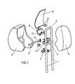
- Figure 1 is an exploded perspective view of a headrest constructed according to the invention.
- Figure 2 is a schematic cross-section of the headrest, mounted, without the padded covering.
- Figure 3 is a perspective view of the connecting rod between the frame and the swivelling front body of the headrest.
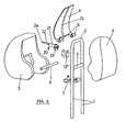
- Figure 4 is a similar view to figure 1, showing a first alternative of embodiment.
- Figure 5 is a side elevation of the support and the internal mechanisms of the headrest of figure 4, in its position of minimum separation of the mobile front body from the fixed rear body.
- Figure 6 is a similar view to figure 5, with the mechanisms in the position corresponding to a maximum separation of the mobile front body from the fixed rear body.
- Figure 7 is a perspective view of the smaller plate included in the headrest of figure 4, with the iron-bearing cone surrounded by an activation coil.
- Figure 8 is a perspective view similar to figure 1, showing a second alternative embodiment.
- Figure 9 is a schematic perspective view of the headrest of figure 9, mounted, without the padded covering.
- Figure 10 is a similar view to figure 9, showing an alternative embodiment.
-
- As can be seen in figure 1, the headrest of the invention includes a frame consisting of two parallel columns, labelled with the
number 1, which are joined on their upper end by anintermediate segment 2, determining an inverted-U shape. Located between the parallel segments orcolumns 1 is acrossbar 3. As is usual, the parallel segments orcolumns 1 are inserted in the back of the seat through top orifices made in said seat. - Mounted on the described frame is the padded element of the headrest, which according to the invention consists of a fixed rear body labelled with the
number 4, and a swivellingfront body 5. - The fixed
rear body 4 is mounted on the frame formed by thecolumns 1 and theupper segment 2, while the swivelling front body is mounted on ashaft 6 that is supported by thecrossbar 3 of the frame by means of an intermediate connectingrod 7, which tightly embraces thecrossbar 3 so that the body cannot rotate freely about the crossbar, thus requiring an effort to adjust manually the position of the front body 5 (by adjusting the headrest shaft). - The
front body 5 includes a frame consisting of two plates, an external larger plate labelled with thenumber 8, which supports thepadded body 5, and a smaller inner plate labelled with thenumber 9, which rests on thelarger plate 8. - The
smaller plate 9 conforms atubular shaft 10 through which passes theswivelling shaft 6. On its part, thelarger plate 8 conformstubular passages 11 on either side of thetubular shaft 10 and aligned with it, for passage of theswivelling shaft 6. In this way the twoplates swivelling shaft 6. - The connecting
rod 7 is mounted on the intermediate segment of thetubular shaft 10, embracing said tubular shaft. On either side of the connectingrod 7 and on the sametubular shaft 10 are mounted twotorsion springs 12 connected on one end to thesmaller plate 9 and on the other end to the connectingrod 7, so that they constantly push theplate 9 towards theplate 8, and the assembly of the two plates and thepadded element 5 mounted on them towards a position of maximum separation with respect to the fixedrear body 9 of the headrest. - The connecting
rod 7 defines a platform in which anelectromagnet 13 is mounted, which as can be seen best in figure 2 is in charge of actuating ahook 14 capable of acting on atooth 15 which forms part of thesmaller plate 9 in order to retain the latter, together with thelarger plate 8, in a position of maximum proximity to therear body 4. - The
plates element 5, are constantly pushed towards the position of maximum separation from therear body 4 by the torsion springs 12. In the position shown in figure 2, theplates padded body 5 are in their position of greatest proximity to therear body 4, as thesmaller plate 9 is retained by thehook 14. - If there is a rear collision, this will be detected by sensors which will send a signal to the vehicle's electronic processor. If this signal is within certain activation ranges the processor will send the corresponding signal to the
electromagnet 13, whose core will move in the direction A of figure 2, thereby turning thehook 4 in the direction B to release thetooth 15, theplates padded element 5 quickly towards the user's head. - At the moment in which the head meets the
body 5, its inertia in a direction opposite to that of travel will make it push against the saidbody 5 and theplates springs 12 to their initial position in which thetooth 15 will once again be retained by thehook 14, thus leaving the headrest ready for subsequent activation as many times as may be necessary. - One alternative can consist in that after the
electromagnet 13 has been activated and thebody 5 has been displaced towards the user's head, said body is fixed in the position of maximum separation from the fixedbody 4. At the moment in which the head meets the swivellingbody 5 the entire headrest structure, together with the back of the seat, will absorb the energy carried by the head. After activation it will be necessary to use a special tool or to take the automobile to a specialised garage in order to rearm the headrest and leave it ready for a new activation. Despite this, the system would still be reversible, as no damaged parts have to be replaced. - The connecting
rod 7 can be a single piece or, as shown in figure 3, comprise twoparts electromagnet 13, not shown, will be mounted on thesegment 7b. - In the embodiment of figures 5 to 7 the swivelling front body is mounted on the
shaft 6, which is supported by thecrossbar 3 of the frame by means of the intermediate connectingrod 7, which tightly embraces thecrossbar 3 so that said connecting rod cannot revolve about the crossbar, requiring an effort to carry out the manual adjustment of the position of the front body 5 (adjusting the inclination of the headrest). - Mounted on said connecting
rod 7 by means of a small support 13' is a cup-shapedelectromagnet 17, in which fits ametal cone 18 mounted above thesmaller plate 9 and surrounded by anactivation coil 19. This magnet is in charge of retaining thesmaller plate 9 in its position of maximum proximity to the fixed rear body by the action of its magnetic field. - If there is a rear collision, this will be detected by sensors which will send a signal to the vehicle's electronic processor. If this signal is within certain activation ranges the processor will send the corresponding signal to the
coil 19 mounted around thecone 18, creating a magnetic field with an opposite sign to that of the magnet so that the force exerted by the torsioned springs is larger than that exerted by the magnet, releasing the smaller plate, which carries with it thepadded body body 4 and thus to its position nearest the user's head. - At the moment in which the head meets the
body 5, because of its inertia in a direction opposite to the direction of travel it will push against thebody 5 and theplates springs 12 to their initial position in which themetal cone 18 is inserted in themagnet 17 and will again be retained by its magnetic field, thereby leaving the headrest ready to be activated as many times as may be necessary. One alternative can consist in that after the magnet has been neutralised and thebody 5 has been displaced towards the user's head, said body is fixed in the position of maximum separation from the fixedbody 4. When the head meets the swivellingbody 5 the entire headrest structure, as well as the seat back, will absorb the energy carried by the head. - After activation it will be necessary to use a special tool or to take the automobile to a specialised garage in order to rearm the headrest and leave it ready for a new activation.
- Despite this, the system would still be reversible as no damaged parts have to be replaced.
- In the example shown in figures 8 and 10, the
front body 5 includes a frame comprised of asingle plate 8 which supports the paddedbody 5. This plate conformstubular passages 9 for passage of the swivellingshaft 6; said plate can be fixed to the shaft so that it cannot revolve about it, or be mounted tightly on said shaft. Thus, theplate 8 is mounted on the swivellingshaft 6 so that a certain effort is required to make it swivel about said shaft. - On the connecting
rod 7, which acts as a platform, is a telescopingpyrotechnic piston 20 mounted by means of asupport 13" which is joined to said connecting rod. Thepyrotechnic piston 20 consists of a casing orchamber 21 where the pyrotechnic component is housed and aplunger 22 axially displaceable in thechamber 21. Assembly of the piston in thesupport 13" is achieved by thechamber 21, by means of a hingedshaft 23 parallel to theshaft 6. Theplunger 22 can end at its external end in a freely revolvingsphere 24. - The
plate 8 is provided on its surface opposite thepyrotechnic piston 20 with avertical groove 25 that defines a guide on which rests the free end of theplunger 22, on thesphere 24 that determines a bearing. - If there is a rear collision, this will be detected by sensors which send a signal to the vehicle's electronic processor. If this signal is within certain activation ranges the processor will send the corresponding signal to the pyrotechnic component housed in the
chamber 21 of thepiston 20, causing its ignition and thereby the displacement of theplunger 22 towards the outside of thechamber 21, until reaching the position of maximum extraction. In this motion theplunger 22 pushes theplate 8, thesphere 24 moving along the groove or guide 25, thereby carrying with it the frontpadded body 5 quickly until it reaches its farthest position to the fixedbody 4 and, consecuently its nearest position to the user's head, with this position being fixed. - When the head meets the padded
body 5 the entire headrest structure together with the seat back will absorb the energy carried by the head. - After activation it will be necessary to take the automobile to a specialised garage to replace the
pyrotechnic piston 20 or to include the required pyrotechnic component in it in order to rearm the headrest and leave it ready for a new activation. - According to the example of embodiment shown in figure 10, the pyrotechnic piston can be jointed between the
plate 8 and the support 13' of the connectingrod 7. For this, for example, theplunger 22 of thepiston 20 can be housed in an undeformable sheath orbushing 26, which would be hinged to theplate 8 by ashaft 27, parallel to theshaft 23 hinging the piston to the support 13', which crosses lugs 28 joined to theplate 8.
Claims (11)
- Headrest for automobile seats, comprising two parallel columns (1) mounted on the seat back which bear a padded element for supporting the head consisting of a fixed rear body (4) and a mobile front body (5), characterised in that the front body (5) can swivel about a horizontal shaft (6) between positions of maximum proximity and maximum separation from the fixed rear body (4), said horizontal shaft being supported through a connecting rod (7) by a parallel crossbar (3) fitted between the parallel columns (1), the assembly incorporating means for retaining the mobile front body (5) in a position of maximum proximity to the rear body (4) and means for driving said mobile front body towards the position of maximum separation from the rear body, it being possible to deactivate said means for retaining the front body.
- Headrest according to claim 1, characterised in that the means for retaining the front body (5) consist of a locking hook (14) and an actuation electromagnet (13), which are mounted on the connecting rod (7), and a tooth (15) which forms part of the front body.
- Headrest according to claim 1, characterised in that the means for driving the mobile front body (5) consist of at least one spring (12).
- Headrest according to previous claims, characterised in that the swivelling front body (5) includes a frame comprised of two plates (8-9) mounted on the same swivelling shaft (6), a larger outer plate (8) which supports the padded covering and a smaller inner plate (9) which rests on the larger plate, the smaller plate conforming a tubular shaft (10) inside which runs the swivelling shaft (6) and to which the aforementioned connecting rod (7) is connected, as well as two torsion springs (12) which are connected on one end to said smaller plate (9) and on the other to the connecting rod (7); said smaller plate having a tooth (15) which is engaged by the hook actuated by the electromagnet (13).
- Headrest according to claim 1, characterised in that the means for retaining the front body in the position of minimum separation from the fixed rear body consist of a magnet (17) mounted on the connecting rod (7) and an iron-bearing core (18) which forms part of the mobile front body (5) and is located opposite the aforementioned magnet, the iron-bearing core (18) being surrounded by a coil (19) which when activated creates a magnetic field of equal or larger strength and opposite sign to that of the magnet, in order to counteract its effect and allow the separation of the iron-bearing core.
- Headrest according to claim 5, characterised in that the aforementioned magnet (17) has a cup-shaped configuration, inside which can be coupled the iron-bearing core (18) when the mobile front body (5) of the headrest is in its position of minimum separation from the fixed rear body.
- Headrest according to claim 5, characterised in that the iron-bearing core (18) is mounted on the smaller plate (9).
- Headrest according to claim 1, characterised in that the means for retaining the mobile front body (5) of the padded element in a position of maximum proximity to the fixed rear body (4) consist of the connecting rod (7) itself, which connects the swivelling shaft (6) of said front body with the crossbar (3) of the frame, the connecting rod (7) embracing tightly said shaft (6) and the crossbar (3) such that the friction between them prevents the free swivelling of the front body (5); and in that the means for driving said front body consist of a pyrotechnic piston (20) mounted between the connecting rod (7) and the plate (8), which is comprised of a casing or chamber (21) and a plunger (22) that is axially displaceable in the chamber, the chamber housing the pyrotechnic component and being connected to the connecting rod (7) by a hinge shaft (23) parallel to the swivelling shaft (6) of the front body (5), and the plunger being connected to the front body, which it pushes to make it swivel when the pyrotechnic component is activated.
- Headrest according to claim 8, characterised in that the plate (8), through which the body (5) is mounted on the swivelling shaft (6), is provided on its front surface with a vertical groove (25) defining a guide on which rests the end of the plunger (22).
- Headrest according to claim 8, characterised in that the plunger (22) of the pyrotechnic piston is provided on its free external end with a freely revolving sphere (24) which determines a bearing by which said plunger rests on the guide (25) of the swivelling front body.
- Headrest according to claim 8, characterised in that the segment of the plunger projecting from the chamber (21) of the pyrotechnic piston is housed in a sleeve or bushing (26) which is hinged to the plate (8) of the swivelling front body by means of a shaft (27) parallel (23) to the shaft hinging the chamber of said piston to the connecting rod.
Applications Claiming Priority (6)
| Application Number | Priority Date | Filing Date | Title |
|---|---|---|---|
| ES200200074U ES1051611Y (en) | 2002-01-14 | 2002-01-14 | REPLACEMENT HEADS FOR MOTOR VEHICLES. |
| ES200200074 | 2002-01-14 | ||
| ES200201399 | 2002-05-31 | ||
| ES200201398U ES1052173Y (en) | 2002-05-31 | 2002-05-31 | REPLACEMENT HEADS FOR MOTOR VEHICLES. |
| ES200201399U ES1052174Y (en) | 2002-05-31 | 2002-05-31 | REPLACEMENT HEADS FOR MOTOR VEHICLES. |
| ES200201398 | 2002-05-31 |
Publications (3)
| Publication Number | Publication Date |
|---|---|
| EP1327557A1 true EP1327557A1 (en) | 2003-07-16 |
| EP1327557B1 EP1327557B1 (en) | 2007-05-16 |
| EP1327557B8 EP1327557B8 (en) | 2007-07-04 |
Family
ID=30773261
Family Applications (1)
| Application Number | Title | Priority Date | Filing Date |
|---|---|---|---|
| EP02380257A Expired - Lifetime EP1327557B8 (en) | 2002-01-14 | 2002-12-10 | Headrest for automobile seats |
Country Status (4)
| Country | Link |
|---|---|
| EP (1) | EP1327557B8 (en) |
| AT (1) | ATE362436T1 (en) |
| DE (1) | DE60220134T2 (en) |
| ES (1) | ES2284802T3 (en) |
Cited By (1)
| Publication number | Priority date | Publication date | Assignee | Title |
|---|---|---|---|---|
| EP2527197A3 (en) * | 2011-05-23 | 2017-11-29 | Batz, S.Coop. | Headrest for motor vehicle seats |
Citations (5)
| Publication number | Priority date | Publication date | Assignee | Title |
|---|---|---|---|---|
| DE3900495A1 (en) * | 1989-01-10 | 1990-07-26 | Bayerische Motoren Werke Ag | Head restraint for a motor-vehicle seat |
| DE19757533A1 (en) * | 1997-12-23 | 1998-10-01 | Brose Fahrzeugteile | Safety seat for vehicle |
| EP0982186A2 (en) * | 1998-08-26 | 2000-03-01 | Grammer Ag | Vehicle seat with a headrest |
| EP1122122A1 (en) * | 2000-02-03 | 2001-08-08 | Keiper GmbH & Co. | Headrest for a vehicle seat |
| EP1193114A1 (en) * | 2000-09-26 | 2002-04-03 | DaimlerChrysler AG | Headrest |
-
2002
- 2002-12-10 ES ES02380257T patent/ES2284802T3/en not_active Expired - Lifetime
- 2002-12-10 DE DE60220134T patent/DE60220134T2/en not_active Expired - Lifetime
- 2002-12-10 AT AT02380257T patent/ATE362436T1/en not_active IP Right Cessation
- 2002-12-10 EP EP02380257A patent/EP1327557B8/en not_active Expired - Lifetime
Patent Citations (5)
| Publication number | Priority date | Publication date | Assignee | Title |
|---|---|---|---|---|
| DE3900495A1 (en) * | 1989-01-10 | 1990-07-26 | Bayerische Motoren Werke Ag | Head restraint for a motor-vehicle seat |
| DE19757533A1 (en) * | 1997-12-23 | 1998-10-01 | Brose Fahrzeugteile | Safety seat for vehicle |
| EP0982186A2 (en) * | 1998-08-26 | 2000-03-01 | Grammer Ag | Vehicle seat with a headrest |
| EP1122122A1 (en) * | 2000-02-03 | 2001-08-08 | Keiper GmbH & Co. | Headrest for a vehicle seat |
| EP1193114A1 (en) * | 2000-09-26 | 2002-04-03 | DaimlerChrysler AG | Headrest |
Cited By (1)
| Publication number | Priority date | Publication date | Assignee | Title |
|---|---|---|---|---|
| EP2527197A3 (en) * | 2011-05-23 | 2017-11-29 | Batz, S.Coop. | Headrest for motor vehicle seats |
Also Published As
| Publication number | Publication date |
|---|---|
| EP1327557B8 (en) | 2007-07-04 |
| DE60220134T2 (en) | 2007-11-29 |
| DE60220134D1 (en) | 2007-06-28 |
| ES2284802T3 (en) | 2007-11-16 |
| ATE362436T1 (en) | 2007-06-15 |
| EP1327557B1 (en) | 2007-05-16 |
Similar Documents
| Publication | Publication Date | Title |
|---|---|---|
| US5772280A (en) | Dynamic actuation system for an articulated headrest portion of an automotive seat | |
| JP4842273B2 (en) | Reclining mechanism | |
| US6623073B2 (en) | Head restraint for a vehicle seat | |
| US8146988B2 (en) | Resettable seat with energy absorber | |
| US6899395B2 (en) | Cam-driven four-way head restraint assembly | |
| US6550865B2 (en) | Headrest assembly for protecting the neck of a vehicle seat occupant | |
| CN108725280B (en) | Armrest module for a motor vehicle seat | |
| EP1584514B1 (en) | A neck rest for seats of automobiles | |
| US6688697B2 (en) | Head restraint | |
| EP0065982B1 (en) | Vehicle crashworthy seat | |
| CN101734181B (en) | Active headrest apparatus for vehicle and actuator thereof | |
| US8936311B2 (en) | Headrest for motor vehicle seats | |
| US6514001B1 (en) | Variable length shaft and method for making the same | |
| US20040160095A1 (en) | Collapsible vehicle safety seat | |
| GB2418849A (en) | Linear adjustable active head restraint | |
| KR20080059251A (en) | Active Head Suppression | |
| AU728411B3 (en) | Suspension seat | |
| US20040160094A1 (en) | A vehicular seat assembly having a movable headrest and a vehicle which incorporates the vehicular seat assembly | |
| US20110012399A1 (en) | Head rest for a vehicle | |
| EP1327557B1 (en) | Headrest for automobile seats | |
| US5265936A (en) | Locking device for locking two elements that are articulated relative to one another | |
| EP1636065B1 (en) | A vehicle seat | |
| KR20230061083A (en) | Seat back inclination angle adjustment device | |
| WO2010002327A1 (en) | Whiplash protection arrangement | |
| WO2003026921A1 (en) | A safety device for a seat of a motor driven vehicle |
Legal Events
| Date | Code | Title | Description |
|---|---|---|---|
| PUAI | Public reference made under article 153(3) epc to a published international application that has entered the european phase |
Free format text: ORIGINAL CODE: 0009012 |
|
| AK | Designated contracting states |
Designated state(s): AT BE BG CH CY CZ DE DK EE ES FI FR GB GR IE IT LI LU MC NL PT SE SI SK TR |
|
| AX | Request for extension of the european patent |
Extension state: AL LT LV MK RO |
|
| 17P | Request for examination filed |
Effective date: 20030923 |
|
| AKX | Designation fees paid |
Designated state(s): AT BE BG CH CY CZ DE DK EE ES FI FR GB GR IE IT LI LU MC NL PT SE SI SK TR |
|
| GRAP | Despatch of communication of intention to grant a patent |
Free format text: ORIGINAL CODE: EPIDOSNIGR1 |
|
| GRAS | Grant fee paid |
Free format text: ORIGINAL CODE: EPIDOSNIGR3 |
|
| GRAA | (expected) grant |
Free format text: ORIGINAL CODE: 0009210 |
|
| AK | Designated contracting states |
Kind code of ref document: B1 Designated state(s): AT BE BG CH CY CZ DE DK EE ES FI FR GB GR IE IT LI LU MC NL PT SE SI SK TR |
|
| PG25 | Lapsed in a contracting state [announced via postgrant information from national office to epo] |
Ref country code: LI Free format text: LAPSE BECAUSE OF FAILURE TO SUBMIT A TRANSLATION OF THE DESCRIPTION OR TO PAY THE FEE WITHIN THE PRESCRIBED TIME-LIMIT Effective date: 20070516 Ref country code: CH Free format text: LAPSE BECAUSE OF FAILURE TO SUBMIT A TRANSLATION OF THE DESCRIPTION OR TO PAY THE FEE WITHIN THE PRESCRIBED TIME-LIMIT Effective date: 20070516 Ref country code: FI Free format text: LAPSE BECAUSE OF FAILURE TO SUBMIT A TRANSLATION OF THE DESCRIPTION OR TO PAY THE FEE WITHIN THE PRESCRIBED TIME-LIMIT Effective date: 20070516 |
|
| REG | Reference to a national code |
Ref country code: GB Ref legal event code: FG4D |
|
| RAP2 | Party data changed (patent owner data changed or rights of a patent transferred) |
Owner name: SEAT, S.A. |
|
| REG | Reference to a national code |
Ref country code: CH Ref legal event code: EP |
|
| REG | Reference to a national code |
Ref country code: IE Ref legal event code: FG4D |
|
| REF | Corresponds to: |
Ref document number: 60220134 Country of ref document: DE Date of ref document: 20070628 Kind code of ref document: P |
|
| NLT2 | Nl: modifications (of names), taken from the european patent patent bulletin |
Owner name: SEAT, S.A. Effective date: 20070613 |
|
| PG25 | Lapsed in a contracting state [announced via postgrant information from national office to epo] |
Ref country code: SE Free format text: LAPSE BECAUSE OF FAILURE TO SUBMIT A TRANSLATION OF THE DESCRIPTION OR TO PAY THE FEE WITHIN THE PRESCRIBED TIME-LIMIT Effective date: 20070816 |
|
| ET | Fr: translation filed | ||
| NLV1 | Nl: lapsed or annulled due to failure to fulfill the requirements of art. 29p and 29m of the patents act | ||
| REG | Reference to a national code |
Ref country code: ES Ref legal event code: FG2A Ref document number: 2284802 Country of ref document: ES Kind code of ref document: T3 |
|
| PG25 | Lapsed in a contracting state [announced via postgrant information from national office to epo] |
Ref country code: AT Free format text: LAPSE BECAUSE OF FAILURE TO SUBMIT A TRANSLATION OF THE DESCRIPTION OR TO PAY THE FEE WITHIN THE PRESCRIBED TIME-LIMIT Effective date: 20070516 |
|
| REG | Reference to a national code |
Ref country code: CH Ref legal event code: PL |
|
| PG25 | Lapsed in a contracting state [announced via postgrant information from national office to epo] |
Ref country code: BE Free format text: LAPSE BECAUSE OF FAILURE TO SUBMIT A TRANSLATION OF THE DESCRIPTION OR TO PAY THE FEE WITHIN THE PRESCRIBED TIME-LIMIT Effective date: 20070516 |
|
| PG25 | Lapsed in a contracting state [announced via postgrant information from national office to epo] |
Ref country code: NL Free format text: LAPSE BECAUSE OF FAILURE TO SUBMIT A TRANSLATION OF THE DESCRIPTION OR TO PAY THE FEE WITHIN THE PRESCRIBED TIME-LIMIT Effective date: 20070516 Ref country code: BG Free format text: LAPSE BECAUSE OF FAILURE TO SUBMIT A TRANSLATION OF THE DESCRIPTION OR TO PAY THE FEE WITHIN THE PRESCRIBED TIME-LIMIT Effective date: 20070816 Ref country code: PT Free format text: LAPSE BECAUSE OF FAILURE TO SUBMIT A TRANSLATION OF THE DESCRIPTION OR TO PAY THE FEE WITHIN THE PRESCRIBED TIME-LIMIT Effective date: 20071016 Ref country code: CZ Free format text: LAPSE BECAUSE OF FAILURE TO SUBMIT A TRANSLATION OF THE DESCRIPTION OR TO PAY THE FEE WITHIN THE PRESCRIBED TIME-LIMIT Effective date: 20070516 Ref country code: DK Free format text: LAPSE BECAUSE OF FAILURE TO SUBMIT A TRANSLATION OF THE DESCRIPTION OR TO PAY THE FEE WITHIN THE PRESCRIBED TIME-LIMIT Effective date: 20070516 Ref country code: SI Free format text: LAPSE BECAUSE OF FAILURE TO SUBMIT A TRANSLATION OF THE DESCRIPTION OR TO PAY THE FEE WITHIN THE PRESCRIBED TIME-LIMIT Effective date: 20070516 |
|
| PG25 | Lapsed in a contracting state [announced via postgrant information from national office to epo] |
Ref country code: SK Free format text: LAPSE BECAUSE OF FAILURE TO SUBMIT A TRANSLATION OF THE DESCRIPTION OR TO PAY THE FEE WITHIN THE PRESCRIBED TIME-LIMIT Effective date: 20070516 |
|
| PLBE | No opposition filed within time limit |
Free format text: ORIGINAL CODE: 0009261 |
|
| STAA | Information on the status of an ep patent application or granted ep patent |
Free format text: STATUS: NO OPPOSITION FILED WITHIN TIME LIMIT |
|
| 26N | No opposition filed |
Effective date: 20080219 |
|
| PG25 | Lapsed in a contracting state [announced via postgrant information from national office to epo] |
Ref country code: GR Free format text: LAPSE BECAUSE OF FAILURE TO SUBMIT A TRANSLATION OF THE DESCRIPTION OR TO PAY THE FEE WITHIN THE PRESCRIBED TIME-LIMIT Effective date: 20070817 |
|
| PG25 | Lapsed in a contracting state [announced via postgrant information from national office to epo] |
Ref country code: MC Free format text: LAPSE BECAUSE OF NON-PAYMENT OF DUE FEES Effective date: 20071231 |
|
| PG25 | Lapsed in a contracting state [announced via postgrant information from national office to epo] |
Ref country code: IE Free format text: LAPSE BECAUSE OF NON-PAYMENT OF DUE FEES Effective date: 20071210 |
|
| PG25 | Lapsed in a contracting state [announced via postgrant information from national office to epo] |
Ref country code: EE Free format text: LAPSE BECAUSE OF FAILURE TO SUBMIT A TRANSLATION OF THE DESCRIPTION OR TO PAY THE FEE WITHIN THE PRESCRIBED TIME-LIMIT Effective date: 20070516 |
|
| PG25 | Lapsed in a contracting state [announced via postgrant information from national office to epo] |
Ref country code: CY Free format text: LAPSE BECAUSE OF FAILURE TO SUBMIT A TRANSLATION OF THE DESCRIPTION OR TO PAY THE FEE WITHIN THE PRESCRIBED TIME-LIMIT Effective date: 20070516 |
|
| PG25 | Lapsed in a contracting state [announced via postgrant information from national office to epo] |
Ref country code: LU Free format text: LAPSE BECAUSE OF NON-PAYMENT OF DUE FEES Effective date: 20071210 |
|
| PG25 | Lapsed in a contracting state [announced via postgrant information from national office to epo] |
Ref country code: TR Free format text: LAPSE BECAUSE OF FAILURE TO SUBMIT A TRANSLATION OF THE DESCRIPTION OR TO PAY THE FEE WITHIN THE PRESCRIBED TIME-LIMIT Effective date: 20070516 |
|
| PGFP | Annual fee paid to national office [announced via postgrant information from national office to epo] |
Ref country code: DE Payment date: 20120103 Year of fee payment: 10 |
|
| PGFP | Annual fee paid to national office [announced via postgrant information from national office to epo] |
Ref country code: IT Payment date: 20121220 Year of fee payment: 11 |
|
| PGFP | Annual fee paid to national office [announced via postgrant information from national office to epo] |
Ref country code: GB Payment date: 20130102 Year of fee payment: 11 Ref country code: FR Payment date: 20130121 Year of fee payment: 11 |
|
| REG | Reference to a national code |
Ref country code: DE Ref legal event code: R119 Ref document number: 60220134 Country of ref document: DE Effective date: 20130702 |
|
| PG25 | Lapsed in a contracting state [announced via postgrant information from national office to epo] |
Ref country code: DE Free format text: LAPSE BECAUSE OF NON-PAYMENT OF DUE FEES Effective date: 20130702 |
|
| GBPC | Gb: european patent ceased through non-payment of renewal fee |
Effective date: 20131210 |
|
| REG | Reference to a national code |
Ref country code: FR Ref legal event code: ST Effective date: 20140829 |
|
| PG25 | Lapsed in a contracting state [announced via postgrant information from national office to epo] |
Ref country code: FR Free format text: LAPSE BECAUSE OF NON-PAYMENT OF DUE FEES Effective date: 20131231 Ref country code: GB Free format text: LAPSE BECAUSE OF NON-PAYMENT OF DUE FEES Effective date: 20131210 |
|
| PG25 | Lapsed in a contracting state [announced via postgrant information from national office to epo] |
Ref country code: IT Free format text: LAPSE BECAUSE OF NON-PAYMENT OF DUE FEES Effective date: 20131231 |
|
| PGFP | Annual fee paid to national office [announced via postgrant information from national office to epo] |
Ref country code: ES Payment date: 20160121 Year of fee payment: 14 |
|
| PG25 | Lapsed in a contracting state [announced via postgrant information from national office to epo] |
Ref country code: IT Free format text: LAPSE BECAUSE OF NON-PAYMENT OF DUE FEES Effective date: 20131210 |
|
| PG25 | Lapsed in a contracting state [announced via postgrant information from national office to epo] |
Ref country code: ES Free format text: LAPSE BECAUSE OF NON-PAYMENT OF DUE FEES Effective date: 20161211 |
|
| REG | Reference to a national code |
Ref country code: ES Ref legal event code: FD2A Effective date: 20181116 |