EP1327553A2 - Running control system, parking assist system, and method for running control - Google Patents
Running control system, parking assist system, and method for running control Download PDFInfo
- Publication number
- EP1327553A2 EP1327553A2 EP03000350A EP03000350A EP1327553A2 EP 1327553 A2 EP1327553 A2 EP 1327553A2 EP 03000350 A EP03000350 A EP 03000350A EP 03000350 A EP03000350 A EP 03000350A EP 1327553 A2 EP1327553 A2 EP 1327553A2
- Authority
- EP
- European Patent Office
- Prior art keywords
- vehicle speed
- vehicle
- control system
- control mode
- running control
- Prior art date
- Legal status (The legal status is an assumption and is not a legal conclusion. Google has not performed a legal analysis and makes no representation as to the accuracy of the status listed.)
- Granted
Links
Images


Classifications
-
- B—PERFORMING OPERATIONS; TRANSPORTING
- B60—VEHICLES IN GENERAL
- B60W—CONJOINT CONTROL OF VEHICLE SUB-UNITS OF DIFFERENT TYPE OR DIFFERENT FUNCTION; CONTROL SYSTEMS SPECIALLY ADAPTED FOR HYBRID VEHICLES; ROAD VEHICLE DRIVE CONTROL SYSTEMS FOR PURPOSES NOT RELATED TO THE CONTROL OF A PARTICULAR SUB-UNIT
- B60W10/00—Conjoint control of vehicle sub-units of different type or different function
- B60W10/04—Conjoint control of vehicle sub-units of different type or different function including control of propulsion units
-
- B—PERFORMING OPERATIONS; TRANSPORTING
- B60—VEHICLES IN GENERAL
- B60K—ARRANGEMENT OR MOUNTING OF PROPULSION UNITS OR OF TRANSMISSIONS IN VEHICLES; ARRANGEMENT OR MOUNTING OF PLURAL DIVERSE PRIME-MOVERS IN VEHICLES; AUXILIARY DRIVES FOR VEHICLES; INSTRUMENTATION OR DASHBOARDS FOR VEHICLES; ARRANGEMENTS IN CONNECTION WITH COOLING, AIR INTAKE, GAS EXHAUST OR FUEL SUPPLY OF PROPULSION UNITS IN VEHICLES
- B60K31/00—Vehicle fittings, acting on a single sub-unit only, for automatically controlling vehicle speed, i.e. preventing speed from exceeding an arbitrarily established velocity or maintaining speed at a particular velocity, as selected by the vehicle operator
- B60K31/06—Vehicle fittings, acting on a single sub-unit only, for automatically controlling vehicle speed, i.e. preventing speed from exceeding an arbitrarily established velocity or maintaining speed at a particular velocity, as selected by the vehicle operator including fluid pressure actuated servomechanism in which the vehicle velocity affecting element is actuated by fluid pressure
- B60K31/10—Vehicle fittings, acting on a single sub-unit only, for automatically controlling vehicle speed, i.e. preventing speed from exceeding an arbitrarily established velocity or maintaining speed at a particular velocity, as selected by the vehicle operator including fluid pressure actuated servomechanism in which the vehicle velocity affecting element is actuated by fluid pressure and means for comparing one electrical quantity, e.g. voltage, pulse, waveform, flux, or the like, with another quantity of a like kind, which comparison means is involved in the development of a pressure which is fed into the controlling means
-
- B—PERFORMING OPERATIONS; TRANSPORTING
- B60—VEHICLES IN GENERAL
- B60T—VEHICLE BRAKE CONTROL SYSTEMS OR PARTS THEREOF; BRAKE CONTROL SYSTEMS OR PARTS THEREOF, IN GENERAL; ARRANGEMENT OF BRAKING ELEMENTS ON VEHICLES IN GENERAL; PORTABLE DEVICES FOR PREVENTING UNWANTED MOVEMENT OF VEHICLES; VEHICLE MODIFICATIONS TO FACILITATE COOLING OF BRAKES
- B60T7/00—Brake-action initiating means
- B60T7/12—Brake-action initiating means for automatic initiation; for initiation not subject to will of driver or passenger
-
- B—PERFORMING OPERATIONS; TRANSPORTING
- B60—VEHICLES IN GENERAL
- B60T—VEHICLE BRAKE CONTROL SYSTEMS OR PARTS THEREOF; BRAKE CONTROL SYSTEMS OR PARTS THEREOF, IN GENERAL; ARRANGEMENT OF BRAKING ELEMENTS ON VEHICLES IN GENERAL; PORTABLE DEVICES FOR PREVENTING UNWANTED MOVEMENT OF VEHICLES; VEHICLE MODIFICATIONS TO FACILITATE COOLING OF BRAKES
- B60T7/00—Brake-action initiating means
- B60T7/12—Brake-action initiating means for automatic initiation; for initiation not subject to will of driver or passenger
- B60T7/122—Brake-action initiating means for automatic initiation; for initiation not subject to will of driver or passenger for locking of reverse movement
-
- B—PERFORMING OPERATIONS; TRANSPORTING
- B60—VEHICLES IN GENERAL
- B60W—CONJOINT CONTROL OF VEHICLE SUB-UNITS OF DIFFERENT TYPE OR DIFFERENT FUNCTION; CONTROL SYSTEMS SPECIALLY ADAPTED FOR HYBRID VEHICLES; ROAD VEHICLE DRIVE CONTROL SYSTEMS FOR PURPOSES NOT RELATED TO THE CONTROL OF A PARTICULAR SUB-UNIT
- B60W10/00—Conjoint control of vehicle sub-units of different type or different function
- B60W10/18—Conjoint control of vehicle sub-units of different type or different function including control of braking systems
-
- B—PERFORMING OPERATIONS; TRANSPORTING
- B60—VEHICLES IN GENERAL
- B60W—CONJOINT CONTROL OF VEHICLE SUB-UNITS OF DIFFERENT TYPE OR DIFFERENT FUNCTION; CONTROL SYSTEMS SPECIALLY ADAPTED FOR HYBRID VEHICLES; ROAD VEHICLE DRIVE CONTROL SYSTEMS FOR PURPOSES NOT RELATED TO THE CONTROL OF A PARTICULAR SUB-UNIT
- B60W30/00—Purposes of road vehicle drive control systems not related to the control of a particular sub-unit, e.g. of systems using conjoint control of vehicle sub-units
- B60W30/14—Adaptive cruise control
- B60W30/143—Speed control
- B60W30/146—Speed limiting
-
- B—PERFORMING OPERATIONS; TRANSPORTING
- B60—VEHICLES IN GENERAL
- B60W—CONJOINT CONTROL OF VEHICLE SUB-UNITS OF DIFFERENT TYPE OR DIFFERENT FUNCTION; CONTROL SYSTEMS SPECIALLY ADAPTED FOR HYBRID VEHICLES; ROAD VEHICLE DRIVE CONTROL SYSTEMS FOR PURPOSES NOT RELATED TO THE CONTROL OF A PARTICULAR SUB-UNIT
- B60W30/00—Purposes of road vehicle drive control systems not related to the control of a particular sub-unit, e.g. of systems using conjoint control of vehicle sub-units
- B60W30/18—Propelling the vehicle
- B60W30/18009—Propelling the vehicle related to particular drive situations
- B60W30/18063—Creeping
-
- B—PERFORMING OPERATIONS; TRANSPORTING
- B60—VEHICLES IN GENERAL
- B60W—CONJOINT CONTROL OF VEHICLE SUB-UNITS OF DIFFERENT TYPE OR DIFFERENT FUNCTION; CONTROL SYSTEMS SPECIALLY ADAPTED FOR HYBRID VEHICLES; ROAD VEHICLE DRIVE CONTROL SYSTEMS FOR PURPOSES NOT RELATED TO THE CONTROL OF A PARTICULAR SUB-UNIT
- B60W30/00—Purposes of road vehicle drive control systems not related to the control of a particular sub-unit, e.g. of systems using conjoint control of vehicle sub-units
- B60W30/18—Propelling the vehicle
- B60W30/1819—Propulsion control with control means using analogue circuits, relays or mechanical links
-
- B—PERFORMING OPERATIONS; TRANSPORTING
- B62—LAND VEHICLES FOR TRAVELLING OTHERWISE THAN ON RAILS
- B62D—MOTOR VEHICLES; TRAILERS
- B62D15/00—Steering not otherwise provided for
- B62D15/02—Steering position indicators ; Steering position determination; Steering aids
- B62D15/027—Parking aids, e.g. instruction means
- B62D15/0285—Parking performed automatically
-
- B—PERFORMING OPERATIONS; TRANSPORTING
- B60—VEHICLES IN GENERAL
- B60T—VEHICLE BRAKE CONTROL SYSTEMS OR PARTS THEREOF; BRAKE CONTROL SYSTEMS OR PARTS THEREOF, IN GENERAL; ARRANGEMENT OF BRAKING ELEMENTS ON VEHICLES IN GENERAL; PORTABLE DEVICES FOR PREVENTING UNWANTED MOVEMENT OF VEHICLES; VEHICLE MODIFICATIONS TO FACILITATE COOLING OF BRAKES
- B60T2201/00—Particular use of vehicle brake systems; Special systems using also the brakes; Special software modules within the brake system controller
- B60T2201/04—Hill descent control
-
- B—PERFORMING OPERATIONS; TRANSPORTING
- B60—VEHICLES IN GENERAL
- B60T—VEHICLE BRAKE CONTROL SYSTEMS OR PARTS THEREOF; BRAKE CONTROL SYSTEMS OR PARTS THEREOF, IN GENERAL; ARRANGEMENT OF BRAKING ELEMENTS ON VEHICLES IN GENERAL; PORTABLE DEVICES FOR PREVENTING UNWANTED MOVEMENT OF VEHICLES; VEHICLE MODIFICATIONS TO FACILITATE COOLING OF BRAKES
- B60T2201/00—Particular use of vehicle brake systems; Special systems using also the brakes; Special software modules within the brake system controller
- B60T2201/10—Automatic or semi-automatic parking aid systems
-
- B—PERFORMING OPERATIONS; TRANSPORTING
- B60—VEHICLES IN GENERAL
- B60W—CONJOINT CONTROL OF VEHICLE SUB-UNITS OF DIFFERENT TYPE OR DIFFERENT FUNCTION; CONTROL SYSTEMS SPECIALLY ADAPTED FOR HYBRID VEHICLES; ROAD VEHICLE DRIVE CONTROL SYSTEMS FOR PURPOSES NOT RELATED TO THE CONTROL OF A PARTICULAR SUB-UNIT
- B60W2540/00—Input parameters relating to occupants
- B60W2540/12—Brake pedal position
-
- B—PERFORMING OPERATIONS; TRANSPORTING
- B60—VEHICLES IN GENERAL
- B60W—CONJOINT CONTROL OF VEHICLE SUB-UNITS OF DIFFERENT TYPE OR DIFFERENT FUNCTION; CONTROL SYSTEMS SPECIALLY ADAPTED FOR HYBRID VEHICLES; ROAD VEHICLE DRIVE CONTROL SYSTEMS FOR PURPOSES NOT RELATED TO THE CONTROL OF A PARTICULAR SUB-UNIT
- B60W2552/00—Input parameters relating to infrastructure
- B60W2552/15—Road slope, i.e. the inclination of a road segment in the longitudinal direction
-
- B—PERFORMING OPERATIONS; TRANSPORTING
- B60—VEHICLES IN GENERAL
- B60W—CONJOINT CONTROL OF VEHICLE SUB-UNITS OF DIFFERENT TYPE OR DIFFERENT FUNCTION; CONTROL SYSTEMS SPECIALLY ADAPTED FOR HYBRID VEHICLES; ROAD VEHICLE DRIVE CONTROL SYSTEMS FOR PURPOSES NOT RELATED TO THE CONTROL OF A PARTICULAR SUB-UNIT
- B60W30/00—Purposes of road vehicle drive control systems not related to the control of a particular sub-unit, e.g. of systems using conjoint control of vehicle sub-units
- B60W30/06—Automatic manoeuvring for parking
Definitions
- the invention relates to a running control system provided with a low speed mode in which a vehicle runs at or under a predetermined upper limit vehicle speed, and a control method for that running control. More particularly, the invention relates to a running control system which adjusts a vehicle speed by controlling a braking force while applying a driving force to the vehicle.
- a variety of technologies for maintaining a vehicle speed within a predetermined range when the vehicle is running have been known, such as an automatic cruise system which is operable to obtain a predetermined vehicle speed in a relatively high vehicle speed range by automatically adjusting an accelerator opening.
- an automatic cruise system which is operable to obtain a predetermined vehicle speed in a relatively high vehicle speed range by automatically adjusting an accelerator opening.
- the system disclosed in this publication performs automatic parking by creeping.
- the vehicle speed is basically controlled by the driver, and informing means informs the driver when the vehicle speed exceeds the speed range appropriate for automatic parking, thus urging the driver to apply the brake.
- Japanese Patent Laid-Open Publication No.10-297520 discloses a system which monitors the braking force and the driving force which are applied to the vehicle.
- the system is adapted to cancel the automatic parking when the braking force and driving force are out of predetermined ranges and it is therefore impossible to control the running speed of the vehicle within a speed range appropriate for parking.
- the braking force required to maintain the proper vehicle speed increases since the vehicle accelerates due to gravity.
- a running control system is provided with a vehicle speed control mode for generating a predetermined driving torque and applying a braking force to a vehicle such that a vehicle speed thereof does not exceed the upper limit, and includes a control portion for determining an inclination of a road surface and setting an operating state of the vehicle speed control mode in accordance with the inclination.
- the running control system determines the inclination of the road surface, determines whether or not to execute the vehicle speed control mode depending on the determined inclination of the road surface, and sets the operating state such as conditions for executing the vehicle speed control mode. This enables a driver to reliably make use of the vehicle speed range, which is from a state where the vehicle is stationary to an upper limit vehicle speed, only by a braking operation at the time of executing the vehicle speed control mode. It is sufficient to set the vehicle speed control mode in accordance with the inclination. It is not necessary to determine specifically the angle of inclination.
- the degree of the inclination of the road surface can be determined based on a component of a gravitational acceleration in the road surface direction, corresponding to the degree of inclination, or excessive braking force corresponding to that component.
- the vehicle speed control mode when it is determined that the vehicle speed exceeds the upper limit vehicle speed even when a predetermined braking force is applied to the vehicle with the determined inclination of the road surface, it is preferable to prohibit the operation of the vehicle speed control mode since it is difficult to make use of the vehicle speed range in the vicinity of where the vehicle is stationary or creeping.
- a parking assist system which assists a driver in moving a vehicle to a target parking position that is set only by a braking operation by the driver using position detecting means and an automatic steering system is characterized by including a running control system according to the invention, and setting a state of a parking assist operation depending on a state of an operation of the vehicle speed control mode.
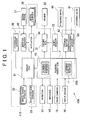
- FIG. 1 is a block diagram of a parking assist system 100 according to the invention.
- the parking assist system 100 includes an automatic steering system 120 in addition to a running control system 110, and is controlled by a parking assist ECU 1, serving as a control system.
- the parking assist ECU 1 is provided with a CPU, ROM, RAM, an input signal circuit, an output signal circuit, a power circuit and the like, and includes a running control portion 10 for controlling the running control system 110 and a steering control portion 11 for controlling the automatic steering system 120.
- the running control portion 10 and the steering control portion 11 may be provided as separate pieces or sets of hardware in the parking assist ECU 1, or may be provided as separate software programs, to be executed by the same piece or set of hardware including a CPU, ROM, RAM, and so on.
- the running control system 110 is provided with the above-mentioned running control portion 10, a brake system, and a driving system.
- the brake system is an electronically controlled brake (ECB) system for electronically controlling a braking force applied to each wheel by a brake ECU 31.
- ECU 31 electronically controlled brake
- the braking force is controlled by adjusting a brake hydraulic pressure which is applied to a wheel cylinder 38 of a hydraulic brake provided to each wheel by an actuator 34.
- the brake ECU 31 receives output signals from various sensors such as a wheel speed sensor 32 which is provided to each wheel and detects a wheel speed thereof, an acceleration sensor 33 which detects an acceleration of the vehicle, a group of hydraulic sensors (not shown) which is provided inside the actuator 34 and detects the hydraulic pressure applied to an inside thereof and the wheel cylinder 38, and a master cylinder (M/C) hydraulic sensor 36 which detects a hydraulic pressure of a master cylinder 35 that is connected between a brake pedal 37 and the actuator 34.
- sensors such as a wheel speed sensor 32 which is provided to each wheel and detects a wheel speed thereof, an acceleration sensor 33 which detects an acceleration of the vehicle, a group of hydraulic sensors (not shown) which is provided inside the actuator 34 and detects the hydraulic pressure applied to an inside thereof and the wheel cylinder 38, and a master cylinder (M/C) hydraulic sensor 36 which detects a hydraulic pressure of a master cylinder 35 that is connected between a brake pedal 37 and the actuator 34.
- M/C master cylinder
- An engine 22 serving as one component of the driving system is controlled by an engine ECU 21, and the engine ECU 21 and the brake ECU 31 execute a cooperative control by communicating with the running control portion 10. Meanwhile, the engine ECU 21 receives an output from a shift sensor 12 for detecting a shift state of a transmission.
- the automatic steering system 120 includes a driving motor 42 which also serves as a power steering driving device arranged between a steering wheel 40 and a steering gear 41, and a displacement sensor 43 which detects a displacement amount of the steering.
- the steering control portion 11 is adapted to control the driving motor 42 while receiving output signals from the displacement sensor 43.
- An image signal which is captured by a rear camera 15 for capturing an image of an area in back of the vehicle, and an output signal of input means 16 for receiving an operation input from the driver at the time of executing the parking assist are input to the parking assist ECU 1 which includes the running control portion 10 and the steering control portion 11.
- a monitor 18 for displaying information by image for the driver, and a speaker 14 for indicating the information by voice are connected to the parking assist ECU 1.
- FIG. 2 is a diagram illustrating an outline of a parking assist control using the system. An example in which a vehicle 5 is moved from a position shown in the diagram to a position denoted by 5a, and is parallel-parked between a vehicle 61 and a vehicle 62 which are parked along a shoulder 63 will be explained.
- the driver sets a parking assist mode by operating the input means 16 while looking at the image captured by the rear camera 15 displayed on the monitor 13, and sets a target parking position by moving a parking frame displayed on the screen to the position 5a in the diagram.
- P the position of the center of the vehicle
- Pt the position of the center of a target parking position 5a
- the parking assist ECU 1 determines Pt (xt, yt) by image recognition process.
- Pt (xt, yt) may be determined, for example, as a relative coordinate whose origin point is the current vehicle position P (x, y).
- the parking assist ECU 1 determines an optimum route 51 for the center of the vehicle, from P (x, y) to Pt (xt, yt).
- the parking assist ECU 1 determines the routes, and then calculates a steering angle variation corresponding to a steering operation and vehicle center position of gravity necessary to take the route 51.
- the running control portion 10 of the parking assist ECU 1 instructs the engine ECU 21 to increase a torque of the engine 22. Accordingly, the engine 22 rotates at a rotation speed higher than that of a regular idle state, and thereby switches to a torque increased state in which the driving force is strong. This extends the range of vehicle speed which can be adjusted only by the brake pedal 37 without operating the accelerator, and enhances a controllability of the vehicle.
- a wheel cylinder hydraulic pressure (a brake hydraulic pressure) which is applied to the wheel cylinder 38 by the actuator 34 in accordance with the pedal opening is adjusted, and the vehicle speed is adjusted by adjusting the braking force which is applied to each wheel.
- the actuator 34 adjusts the brake hydraulic pressure applied to each wheel cylinder 38 such that the vehicle speed detected by the wheel speed sensor 32 does not exceed the upper limit vehicle speed.
- the steering control portion 11 controls the driving motor 42 so as to steer the steering gear 41 while monitoring an output from the displacement sensor 43 such that a steering angle agrees with a displacement of the steering angle obtained by the parking assist ECU 1. Since the vehicle is moved along the thereby set route, the driver can focus on confirming safe conditions of the route and adjusting the vehicle speed. In a case where there is an obstacle or a pedestrian in the route, when the driver depresses the brake pedal 37, the brake ECU 31 controls the actuator 43 such that a brake force corresponding to the depression amount is applied to the wheel cylinder 38, which allows the vehicle to decelerate or stop in safety.
- the parking assist system according to the embodiment is characterized in that it determines a slope prior to the start of parking assist control, and sets an operation.
- a slope prior to the start of parking assist control
- FIG. 3 is a flow chart illustrating a first operation setting routine. The process is executed while the vehicle is stationary immediately after the parking assist mode is set by the input means 16.
- step S1 wheel speeds W FR to W RL of each wheel which are read by the wheel speed sensor 32, and an acceleration a in a longitudinal direction of the vehicle which is read by the acceleration sensor 33 are read.
- step S2 a vehicle speed V is computed from the wheel speeds W FR to W RL of each wheel.
- the absolute value and a threshold value Vth of the vehicle speed V are compared.
- Vth is an adequately low vehicle speed (for example, 0.5 km/h), and may be set at 0 km/h.
- step S4 When the absolute value of the vehicle speed V is equal to or lower than Vth, it is determined that the vehicle is substantially stationary, and the process proceeds on to step S4. When the absolute value of the vehicle speed V exceeds Vth, the process proceeds on to step S5, where the driver is instructed through the monitor 13 or the speaker 14 to stop the vehicle. Then, after waiting for a predetermined period of time, the process returns to step S1. This makes it possible to stop the vehicle with reliability and execute an accurate determination.
- step S4 an absolute value of the acceleration a and its threshold value ath are compared.
- an acceleration detected by the acceleration sensor 38 is a component of a gravitational acceleration speed g in the road surface direction.
- the acceleration detected by the acceleration sensor 38 is gsin ⁇ , and increases with a increase in the inclination angle ⁇ . Therefore, when it is determined that the absolute value of the acceleration a is equal to or higher than ath, the process proceeds on to step S6, where the driver is informed through the monitor 13 and the speaker 14 that the condition for operating the parking assist system 100 is not fulfilled.
- a driving prohibition flag Xap of the parking assist system 100 is set to 1 in step S7, after which the routine ends. In this case, the above-mentioned parking assist is cancelled.
- step S4 when it is determined that the absolute value of the acceleration a is lower than ath, the process proceeds on to step S8, assuming that the condition for operating the system is fulfilled. Then, the operation prohibiting flag Xap of the parking assist system 100 is set to 0, after which the routine ends. In this case, the above-mentioned parking assist is continuously executed.
- FIG. 4 is a flow chart illustrating the second operation setting routine.
- the routine is repeatedly executed at predetermined intervals of time during the parking assist routine.
- the parking assist control is continued only when the operation prohibiting flag Xap is set to 0 within the routine.
- the operation prohibiting flag Xap is set to 1
- the parking assist control is stopped and canceled. Note that an initial value at the time of setting the parking assist is 0.
- step S11 the wheel speeds W FR to W RL of each wheel which are read by the wheel speed sensor 32, and the acceleration a act of the vehicle in the longitudinal direction which is read by the acceleration sensor 33 are read.
- step S12 the vehicle speed V is computed from the wheel speeds W FR to W RL of each wheel.
- step S13 the absolute value of the vehicle speed V and the threshold value Vth of the vehicle V are compared.
- Vth is a sufficiently low vehicle speed (e.g., 0.5 km/h), but can not be set at 0 km/h unlike the first operation setting process, since the vehicle needs to be moving in order to calculate a deceleration and acceleration to be described later.
- step S14 a deceleration a b by braking is determined from the brake hydraulic pressure, which is an output from a hydraulic sensor (not shown) arranged in the actuator 34 or the wheel cylinder 38. Also, driving torque information based on a rotation speed of the engine 22 from the engine ECU 21 is received and an acceleration a d by the driving torque is determined.
- step S15 an estimated acceleration a cal is obtained as a difference between the acceleration a d and deceleration a b obtained as above and then a deviation ⁇ a between the estimated acceleration a cal and the actual acceleration a act is determined.
- step S16 an absolute value of the determined deviation ⁇ a and a threshold value ⁇ ath are compared.
- the deviation ⁇ a should be 0 since the estimated acceleration a cal substantially agrees with the actual acceleration a act.
- a high absolute value of ⁇ a indicates that the component gsin ⁇ of the gravitational acceleration g in the road surface direction acting in addition to the estimated acceleration a cal is large, that is, the inclination angle ⁇ of the road surface is steep.
- step S16 when it is determined that an absolute value of a deviation ⁇ a is equal to or higher than a threshold value ⁇ ath, the process proceeds on to step S17 to inform the driver through the monitor 13 and the speaker 14 that the condition for operating the parking assist system 100 is not fulfilled. Then, in step S18, the operation prohibiting flag Xap of the parking assist system 100 is set to 1, after which the routine ends. As a result, the parking assist control is cancelled.
- step S16 when it is determined that the absolute value of a deviation ⁇ a is lower than ⁇ ath, the process proceeds on to step S19 assuming that the condition for operating the system is fulfilled, and the operation prohibiting flag Xap of the parking assist system 100 is set to 0, after which the routine ends. In this case, the above-mentioned parking assist control is continued.
- FIG. 5 is a flow chart illustrating the third operation setting routine.
- the routine is repeatedly executed at a predetermined intervals of time during the parking assist routine.
- the parking assist control is continued only when the operation prohibiting flag Xap is set to 0 within the routine.
- the operation prohibiting flag Xap is set to 1
- the parking assist control is stopped and canceled at that point. Note that an initial value of Xap at the setting time of the parking assist is 0.
- the third operation setting routine is different from the first and second operation setting routines in that a control for varying an amount of torque increase is executed in the third operation setting routine.
- step S21 the wheel speeds W FR to W RL of each wheel read by the wheel speed sensor 32, the acceleration a of the vehicle in the longitudinal direction read by the acceleration sensor 33, and a brake hydraulic pressure P, which is an output from a hydraulic sensor (not shown) arranged inside the actuator 34 or the wheel cylinder 38 are read.
- step S22 the vehicle speed V is computed from the wheel speeds W FR to W RL of each wheel.
- step S23 the absolute value of the vehicle speed V and the threshold value Vth are compared.
- Vth is an sufficiently low vehicle speed (e.g., 0.5 km/h).
- Vth cannot be set at 0 km/h, unlike the first operation setting.
- the process proceeds on to step S24, and a brake hydraulic pressure Pcal which is estimated from the current acceleration a is obtained.
- a difference ( ⁇ P) between the actual hydraulic pressure P and the estimated hydraulic pressure Pcal is calculated.
- the brake hydraulic pressure Pcal is calculated on the basis of a relation between an acceleration and a brake hydraulic pressure which are obtained when the vehicle is running on a flat road in a regular torque state (i.e., a state other than the torque increased state).
- Step S25 whether or not the determined ⁇ P exceeds the threshold value ⁇ Pth is determined.
- ⁇ P exceeds the threshold value ⁇ Pth it is determined that the vehicle is in a state where the load placed on the brake system requires a higher hydraulic pressure than the estimated hydraulic pressure, that is, the vehicle is on the downhill slope where the vehicle accelerates due to gravity. Then, a predetermined torque decrease process is executed.
- step S26 determines whether or not the engine is running in the torque increased state.
- step S27 determines whether or not the engine is running in the torque increased state.
- step S28 reduces the torque, which has been increased, by a predetermined amount, after which the routine ends.
- step S28 determines whether or not the torque increase has already been cancelled.
- step S29 the operation prohibiting flag Xap of the parking assist system 100 is set to 1, after which the routine ends.
- step S25 when it is determined that ⁇ P is lower than the threshold value Pth, the process proceeds on to step S30 to determine whether or not ⁇ P is lower than a threshold value - ⁇ Pth.
- ⁇ P is lower than the threshold value - ⁇ Pth, it is determined that the vehicle is in a state where the actually applied hydraulic pressure is considerably lower than the estimated hydraulic pressure, that is, the vehicle is on the uphill slope where the vehicle decelerates due to gravity. Then, a predetermined torque increase process is executed.
- step S31 determines whether or not the engine is currently in the maximum torque increased state.
- step S32 determines whether or not the engine is currently in the maximum torque increased state.
- step S32 determines whether or not the engine is currently in the maximum torque increased state.
- step S32 determines whether or not the engine is currently in the maximum torque increased state.
- step S32 determines whether or not the engine is currently in the maximum torque increased state.
- step S32 determines whether or not the engine is currently in the maximum torque increased state.
- step S32 determines whether or not the engine is currently in the maximum torque increased state.
- step S30 when it is determined in step S30 that ⁇ P is equal to or higher than the threshold value ⁇ Pth, the succeeding processes are skipped, after which the routine ends. In this case, the torque increased state is maintained as it is.
- the vehicle runs on the downhill slope in the torque increased state, and the degree of torque increase is gradually reduced when the braking force is excessive. This prevents excessive braking force from being applied, and suppresses the load on the brake system. Also, on a steeply inclined downhill slope where an excessive load is on the brake system even when the torque increase is cancelled, the parking assist is cancelled and the driver is informed of that fact. This prevents the parking assist from being continued with excessive braking force applied to the vehicle.
- FIG. 6 is a graph showing a relation between the acceleration a and the brake hydraulic pressure P which are used in the routine.
- the actual hydraulic pressure P is between Pcal - ⁇ Pth and Pcal + ⁇ Pth
- no excessive braking force is needed in the low speed range while the vehicle speed range can be used up to the upper limit vehicle speed with a sufficient ability to accelerate and take off.
- the torque increased state is maintained as it is.
- the actual hydraulic pressure P is lower than Pcal - ⁇ Pth, although the braking force is not excessive, adequate acceleration cannot be obtained. It is therefore difficult to make use of the vehicle speed range up to the upper limit vehicle speed, and the ability to accelerate and take off diminishes. In this case, the torque is increased which the torque can be increased.
- each determination threshold value may be different between the uphill slope and the downhill slope.
- the determination threshold values may be set based on a case where the upper limit vehicle speed cannot be obtained in the maximum torque increased state.
- the determination threshold values based on a case where the braking force required to maintain the upper limit vehicle speed is equal to or higher than the predetermined value. In this way, the vehicle speed range from when the vehicle is stationary to the upper limit vehicle speed can be made used of, and also the excessive braking force can be prevented from being applied.
- the invention can be applied to a parking assist system which executes steering guidance that informs the driver of the proper steering amount, but does not automatically switch to the automatic steering.
- the invention can be applied to, for example, an independent running control system which enables a vehicle speed to be controlled only by operating a brake pedal in a wider speed range than the running control system 110 in the above-described embodiments. In this case, parking, stopping, and moving of the vehicle, which are usually repeated, can be carried out in an appropriate manner with the running control system.
- whether the running control is executed is determined according to the inclination of the road surface.
- the state of that operation can be set also according to the inclination of the road surface.
Landscapes
- Engineering & Computer Science (AREA)
- Transportation (AREA)
- Mechanical Engineering (AREA)
- Chemical & Material Sciences (AREA)
- Combustion & Propulsion (AREA)
- Automation & Control Theory (AREA)
- Physics & Mathematics (AREA)
- Fluid Mechanics (AREA)
- Control Of Driving Devices And Active Controlling Of Vehicle (AREA)
- Regulating Braking Force (AREA)
- Steering Control In Accordance With Driving Conditions (AREA)
- Control Of Vehicle Engines Or Engines For Specific Uses (AREA)
Abstract
Description
Claims (17)
- A running control system (110) including a vehicle speed control mode for generating a predetermined driving torque and applying a braking force to a vehicle such that a vehicle speed does not exceed an upper limit vehicle speed, characterized by comprising:a control portion (10) which determines an inclination of a road surface and sets an operation state of the vehicle speed control mode based on a result of that determination.
- The running control system (110) according to claim 1, characterized in that:a determination on whether to execute the vehicle speed control mode is made when setting the operation state of the vehicle speed control mode.
- The running control system (110) according to claim 1, characterized in that:a determination on whether to execute the vehicle speed control mode is made and the predetermined driving torque is adjusted when setting the operation state of the vehicle speed control mode.
- The running control system (110) according to any one of claims 1 to 3, characterized in that:the inclination is determined based on an acceleration of the vehicle at the time of setting the vehicle speed control mode while the vehicle is stationary.
- The running control system (110) according to any one of claims 1 to 3, characterized in that:the inclination is determined based on a deviation between an estimated acceleration which is estimated from a driving force and a braking force, and an actual acceleration.
- The running control system (110) according to any one of claims 1 to 3, characterized in that:the inclination is determined based on a deviation between an actual braking force and a braking force estimated from the acceleration of the vehicle.
- The running control system (110) according to any one of claims 1 to 6, characterized in that:when it is determined that the vehicle cannot run at or above a predetermined vehicle speed with the predetermined driving torque, an operation of the vehicle speed control mode is prohibited.
- The running control system (110) according to any one of claims 1 to 6, characterized in that:when it is determined that the vehicle speed reaches or exceeds the upper limit vehicle speed even when a predetermined braking force is applied, the operation of the vehicle speed control mode is prohibited.
- A parking assist system for assisting a driver in moving a vehicle to a target parking position which is set only by a braking operation by the driver using position detection means (43) and an automatic steering system (120), characterized in that:the running control system (110) according to any one of claims 1 to 8 is provided, and a state of a parking assist operation is set in accordance with a state of an operation of the vehicle speed control mode.
- A method for controlling a running control system (110) including a vehicle speed control mode for generating a predetermined driving torque and applying a braking force to a vehicle such that a vehicle speed does not exceed an upper limit vehicle speed, characterized by comprising the steps of:determining an inclination of a road surface, andsetting an operation state of the vehicle speed control mode based on a result of that determination.
- The method for controlling the running control system (110) according to claim 10, characterized in that:a determination on whether to execute the vehicle speed control mode is made when setting the operation state of the vehicle speed control mode.
- The method for controlling the running control system (110) according to claim 10, characterized in that:a determination on whether to execute the vehicle speed control mode is made and the predetermined driving torque is adjusted when setting the operation state of the vehicle speed control mode.
- The method for controlling the running control system (110) according to any one of claims 10 to 12, characterized in that:the inclination is determined based on an acceleration of the vehicle at the time of setting the vehicle speed control mode while the vehicle is stationary.
- The method for controlling the running control system (110) according to any one of claims 10 to 12, characterized in that:the inclination is determined based on a deviation between an estimated acceleration estimated from a driving force and a braking force, and an actual acceleration.
- The method for controlling the running control system (110) according to any one of claims 10 to 12, characterized in that:the inclination is determined based on a deviation between an actual braking force and a braking force estimated from the acceleration of the vehicle.
- The method for controlling the running control system (110) according to any one of claims 10 to 15, characterized in that:when it is determined that the vehicle cannot run at or above a predetermined vehicle speed with the predetermined driving torque, an operation of the vehicle speed control mode is prohibited.
- The method for controlling the running control system (110) according to any one of claims 10 to 15, characterized in that:when it is determined that the vehicle reaches or exceeds the upper limit vehicle speed even when a predetermined braking force is applied, the operation of the vehicle speed control mode is prohibited.
Applications Claiming Priority (2)
| Application Number | Priority Date | Filing Date | Title |
|---|---|---|---|
| JP2002005078 | 2002-01-11 | ||
| JP2002005078A JP3755464B2 (en) | 2002-01-11 | 2002-01-11 | Parking assistance device |
Publications (3)
| Publication Number | Publication Date |
|---|---|
| EP1327553A2 true EP1327553A2 (en) | 2003-07-16 |
| EP1327553A3 EP1327553A3 (en) | 2006-08-02 |
| EP1327553B1 EP1327553B1 (en) | 2007-08-08 |
Family
ID=19191062
Family Applications (1)
| Application Number | Title | Priority Date | Filing Date |
|---|---|---|---|
| EP03000350A Expired - Lifetime EP1327553B1 (en) | 2002-01-11 | 2003-01-09 | Parking assist system and method for control thereof |
Country Status (3)
| Country | Link |
|---|---|
| EP (1) | EP1327553B1 (en) |
| JP (1) | JP3755464B2 (en) |
| DE (1) | DE60315362T2 (en) |
Cited By (20)
| Publication number | Priority date | Publication date | Assignee | Title |
|---|---|---|---|---|
| EP1806266A1 (en) * | 2006-01-06 | 2007-07-11 | Fuji Jukogyo Kabushiki Kaisha | Stop determination apparatus, inclination determination apparatus, and electric parking brake controller |
| CN101870288A (en) * | 2010-06-11 | 2010-10-27 | 烟台汽车工程职业学院 | Automobile parking assist braking system |
| US20100318255A1 (en) * | 2009-06-16 | 2010-12-16 | Robert Bosch Gmbh | Determining low-speed driving direction in a vehicle |
| EP2021215A4 (en) * | 2006-05-26 | 2011-03-16 | Scania Cv Abp | Operation control system |
| US20110112716A1 (en) * | 2009-11-09 | 2011-05-12 | Hyundai Motor Company | Apparatus for controlling vehicle chassis having integrated fail safe controller |
| WO2011069589A1 (en) * | 2009-12-12 | 2011-06-16 | Volkswagen Aktiengesellschaft | Method and device for steering a vehicle toward an object during a parking operation |
| FR2958905A1 (en) * | 2010-02-15 | 2011-10-21 | Bosch Gmbh Robert | METHOD AND DEVICE FOR PARKING A MOTOR VEHICLE |
| CN103318168A (en) * | 2012-03-20 | 2013-09-25 | 比亚迪股份有限公司 | Vehicle safety control system and control method thereof |
| US9002564B2 (en) | 2013-04-23 | 2015-04-07 | Ford Global Technologies, Llc | Enhanced park assist wheel speed compensation technique |
| CN105015544A (en) * | 2015-07-27 | 2015-11-04 | 江苏大学 | Vehicle speed control system and method for full-automatic parking of electric car |
| US20160159397A1 (en) * | 2014-12-03 | 2016-06-09 | Hyundai Mobis Co., Ltd. | Automatic parking controlling apparatus and method of vehicle |
| CN106926845A (en) * | 2017-03-02 | 2017-07-07 | 中国第汽车股份有限公司 | A kind of method for dynamic estimation of vehicle status parameters |
| CN107284444A (en) * | 2016-04-08 | 2017-10-24 | 株式会社万都 | Driving assistance device and the driving assistance method using the device |
| WO2018019716A1 (en) * | 2016-07-25 | 2018-02-01 | Jaguar Land Rover Limited | An apparatus, method and computer program for providing parking assistance within a vehicle |
| CN109789778A (en) * | 2016-10-04 | 2019-05-21 | Lg电子株式会社 | Automatic parking auxiliary device and vehicle including it |
| US10300927B2 (en) | 2014-10-27 | 2019-05-28 | Ford Global Technologies, Llc | Method and device for a vehicle control procedure |
| EP3057833B1 (en) * | 2013-10-16 | 2020-06-17 | Audi AG | Vehicle and method for illuminating a region rearward of a vehicle |
| CN111655559A (en) * | 2018-01-31 | 2020-09-11 | 雷诺股份公司 | System and method for controlling a motor vehicle to overcome low obstacles |
| CN114132314A (en) * | 2021-12-20 | 2022-03-04 | 杭叉集团股份有限公司 | Industrial vehicle turning deceleration control system and method thereof |
| WO2022053113A1 (en) * | 2020-09-14 | 2022-03-17 | Continental Teves Ag & Co. Ohg | Method and system for automated parking of a vehicle |
Families Citing this family (13)
| Publication number | Priority date | Publication date | Assignee | Title |
|---|---|---|---|---|
| JP4713408B2 (en) * | 2006-06-07 | 2011-06-29 | トヨタ自動車株式会社 | Vehicle control device |
| JP4488012B2 (en) * | 2007-02-27 | 2010-06-23 | トヨタ自動車株式会社 | Vehicle travel support device |
| DE102008046367A1 (en) * | 2008-09-09 | 2010-03-11 | Valeo Schalter Und Sensoren Gmbh | Method and device for supporting a parking process of a vehicle |
| JP5633186B2 (en) * | 2010-05-12 | 2014-12-03 | トヨタ自動車株式会社 | Parking assistance device |
| DE102010020202A1 (en) * | 2010-05-12 | 2011-11-17 | Volkswagen Ag | Method for actuating parking assistance system for vehicle, involves monitoring engine of vehicle, in order to detect stop of engine |
| JP2013029054A (en) * | 2011-07-27 | 2013-02-07 | Tomohito Ishii | Recession rate inhibiting device of motor vehicle with automatic transmission |
| DE102011086384B4 (en) * | 2011-11-15 | 2022-03-24 | Bayerische Motoren Werke Aktiengesellschaft | Method for assisting in parking a motor vehicle |
| DE102012202175A1 (en) * | 2012-02-14 | 2013-08-14 | Robert Bosch Gmbh | Method for automatic guidance, in particular parking, of a motor vehicle and driver assistance device |
| KR102638561B1 (en) * | 2016-11-02 | 2024-02-20 | 주식회사 에이치엘클레무브 | Parking asistance system and parking asistance method |
| JP6883238B2 (en) * | 2017-01-23 | 2021-06-09 | 株式会社アイシン | Parking support device |
| CN110723136A (en) * | 2019-10-15 | 2020-01-24 | 重庆长安汽车股份有限公司 | Method and system for activating automatic parking function, storage medium and vehicle |
| CN112012836B (en) * | 2020-09-02 | 2023-08-18 | 三一重机有限公司 | A control method and device for a construction machinery engine |
| JP7540270B2 (en) * | 2020-09-29 | 2024-08-27 | 株式会社アイシン | Parking assistance device, parking assistance method, and program |
Family Cites Families (5)
| Publication number | Priority date | Publication date | Assignee | Title |
|---|---|---|---|---|
| JP3182509B2 (en) * | 1997-04-28 | 2001-07-03 | 本田技研工業株式会社 | Automatic steering system for vehicles with automatic transmission |
| DE19753764A1 (en) * | 1997-12-04 | 1999-06-10 | Itt Mfg Enterprises Inc | Method and device for maneuvering motor vehicles |
| DE19844542A1 (en) * | 1998-09-29 | 2000-03-30 | Bosch Gmbh Robert | Device and method for limiting a rollback speed of a motor vehicle |
| DE19941482B4 (en) * | 1998-09-30 | 2017-11-09 | Robert Bosch Gmbh | Apparatus and method for preventing the backward rolling of a vehicle on a slope |
| DE19954807A1 (en) * | 1999-11-13 | 2001-05-17 | Bosch Gmbh Robert | Controlling vehicle so that on basis of specified value for acceleration and-or retardation of vehicle control signal for at least one adjusting element is formed influencing acceleration and-or retardation of vehicle |
-
2002
- 2002-01-11 JP JP2002005078A patent/JP3755464B2/en not_active Expired - Fee Related
-
2003
- 2003-01-09 DE DE60315362T patent/DE60315362T2/en not_active Expired - Lifetime
- 2003-01-09 EP EP03000350A patent/EP1327553B1/en not_active Expired - Lifetime
Cited By (36)
| Publication number | Priority date | Publication date | Assignee | Title |
|---|---|---|---|---|
| US8086384B2 (en) | 2006-01-06 | 2011-12-27 | Fuji Jukogyo Kabushiki Kaisha | Stop determination apparatus, inclination determination apparatus, and electric parking brake controller |
| EP1806266A1 (en) * | 2006-01-06 | 2007-07-11 | Fuji Jukogyo Kabushiki Kaisha | Stop determination apparatus, inclination determination apparatus, and electric parking brake controller |
| EP2021215A4 (en) * | 2006-05-26 | 2011-03-16 | Scania Cv Abp | Operation control system |
| US20100318255A1 (en) * | 2009-06-16 | 2010-12-16 | Robert Bosch Gmbh | Determining low-speed driving direction in a vehicle |
| US8880288B2 (en) * | 2009-06-16 | 2014-11-04 | Robert Bosch Gmbh | Determining low-speed driving direction in a vehicle |
| US20110112716A1 (en) * | 2009-11-09 | 2011-05-12 | Hyundai Motor Company | Apparatus for controlling vehicle chassis having integrated fail safe controller |
| US20120310459A1 (en) * | 2009-12-12 | 2012-12-06 | Frank Schwitters | Method and Device for Steering a Vehicle Toward an Object During a Parking Operation |
| CN102652091A (en) * | 2009-12-12 | 2012-08-29 | 大众汽车有限公司 | Method and device for steering a vehicle toward an object during a parking operation |
| US9327705B2 (en) | 2009-12-12 | 2016-05-03 | Volkswagen Ag | Method and device for steering a vehicle toward an object during a parking operation |
| WO2011069589A1 (en) * | 2009-12-12 | 2011-06-16 | Volkswagen Aktiengesellschaft | Method and device for steering a vehicle toward an object during a parking operation |
| CN102652091B (en) * | 2009-12-12 | 2017-09-08 | 大众汽车有限公司 | Method and apparatus for controlling automobile touch close-target during parking |
| FR2958905A1 (en) * | 2010-02-15 | 2011-10-21 | Bosch Gmbh Robert | METHOD AND DEVICE FOR PARKING A MOTOR VEHICLE |
| US9114834B2 (en) | 2010-02-15 | 2015-08-25 | Robert Bosch Gmbh | Method and device for parking a motor vehicle |
| CN101870288A (en) * | 2010-06-11 | 2010-10-27 | 烟台汽车工程职业学院 | Automobile parking assist braking system |
| CN103318168A (en) * | 2012-03-20 | 2013-09-25 | 比亚迪股份有限公司 | Vehicle safety control system and control method thereof |
| US9002564B2 (en) | 2013-04-23 | 2015-04-07 | Ford Global Technologies, Llc | Enhanced park assist wheel speed compensation technique |
| EP3057833B1 (en) * | 2013-10-16 | 2020-06-17 | Audi AG | Vehicle and method for illuminating a region rearward of a vehicle |
| US10988145B2 (en) | 2014-10-27 | 2021-04-27 | Ford Global Technologies, Llc | Method and device for a vehicle control procedure |
| US10300927B2 (en) | 2014-10-27 | 2019-05-28 | Ford Global Technologies, Llc | Method and device for a vehicle control procedure |
| US10576995B2 (en) | 2014-10-27 | 2020-03-03 | Ford Global Technologies, Llc | Method and device for a vehicle control procedure |
| US20160159397A1 (en) * | 2014-12-03 | 2016-06-09 | Hyundai Mobis Co., Ltd. | Automatic parking controlling apparatus and method of vehicle |
| CN105857305A (en) * | 2014-12-03 | 2016-08-17 | 现代摩比斯株式会社 | Automatic parking controlling apparatus and method of vehicle |
| US9731764B2 (en) * | 2014-12-03 | 2017-08-15 | Hyundai Mobis Co., Ltd. | Automatic parking controlling apparatus and method of vehicle |
| CN105015544A (en) * | 2015-07-27 | 2015-11-04 | 江苏大学 | Vehicle speed control system and method for full-automatic parking of electric car |
| CN107284444A (en) * | 2016-04-08 | 2017-10-24 | 株式会社万都 | Driving assistance device and the driving assistance method using the device |
| DE112017003732B4 (en) * | 2016-07-25 | 2025-04-24 | Jaguar Land Rover Limited | A DEVICE, A METHOD AND A COMPUTER PROGRAM FOR PROVIDING PARKING ASSISTANCE IN A VEHICLE |
| WO2018019716A1 (en) * | 2016-07-25 | 2018-02-01 | Jaguar Land Rover Limited | An apparatus, method and computer program for providing parking assistance within a vehicle |
| EP3524486A4 (en) * | 2016-10-04 | 2020-06-17 | LG Electronics Inc. -1- | AUTOMATIC PARKING ASSISTANCE DEVICE AND VEHICLE THEREFOR |
| CN109789778A (en) * | 2016-10-04 | 2019-05-21 | Lg电子株式会社 | Automatic parking auxiliary device and vehicle including it |
| CN109789778B (en) * | 2016-10-04 | 2022-02-01 | Lg电子株式会社 | Automatic parking assist device and vehicle comprising same |
| CN106926845A (en) * | 2017-03-02 | 2017-07-07 | 中国第汽车股份有限公司 | A kind of method for dynamic estimation of vehicle status parameters |
| CN111655559A (en) * | 2018-01-31 | 2020-09-11 | 雷诺股份公司 | System and method for controlling a motor vehicle to overcome low obstacles |
| WO2022053113A1 (en) * | 2020-09-14 | 2022-03-17 | Continental Teves Ag & Co. Ohg | Method and system for automated parking of a vehicle |
| US12534066B2 (en) | 2020-09-14 | 2026-01-27 | Continental Automotive Technologies GmbH | Method and system for automated parking of a vehicle |
| CN114132314A (en) * | 2021-12-20 | 2022-03-04 | 杭叉集团股份有限公司 | Industrial vehicle turning deceleration control system and method thereof |
| CN114132314B (en) * | 2021-12-20 | 2023-09-01 | 杭叉集团股份有限公司 | Industrial vehicle turning deceleration control system and method thereof |
Also Published As
| Publication number | Publication date |
|---|---|
| EP1327553B1 (en) | 2007-08-08 |
| DE60315362D1 (en) | 2007-09-20 |
| JP2003206780A (en) | 2003-07-25 |
| DE60315362T2 (en) | 2008-05-08 |
| JP3755464B2 (en) | 2006-03-15 |
| EP1327553A3 (en) | 2006-08-02 |
Similar Documents
| Publication | Publication Date | Title |
|---|---|---|
| EP1327553B1 (en) | Parking assist system and method for control thereof | |
| US6922624B2 (en) | Vehicle brake control apparatus | |
| EP1327554B1 (en) | Vehicle traveling control system | |
| US8406952B2 (en) | Electric parking brake control system and electric parking brake control method | |
| US6056374A (en) | Automatic brake control system | |
| EP3208167B1 (en) | A vehicle control apparatus | |
| EP1327559B1 (en) | Parking assist apparatus for vehicle and control method of same | |
| US6389351B1 (en) | Preceding vehicle follow-up control system | |
| US7762633B2 (en) | Brake control system | |
| EP1070624B1 (en) | Preceding vehicle following control system | |
| US6502908B1 (en) | Control system for a vehicle | |
| JP2002089314A (en) | Travel control device | |
| US9393938B2 (en) | Vehicular brake control apparatus | |
| US6626257B2 (en) | Method and device for automatic speed adjustment in a vehicle | |
| US20100070151A1 (en) | Vehicle Speed Control Device and Method for Controlling Vehicle Speed | |
| US20070299581A1 (en) | Limiting Motor-Vehicle Rollback | |
| JP2004352110A (en) | Driving support device for vehicles | |
| CN111609124B (en) | Vehicle gear automatic control method, device and vehicle | |
| JP2004322764A (en) | Automatic speed controller | |
| JPH08113121A (en) | On-slope starting auxiliary device | |
| JP2003205808A (en) | Parking assistance device | |
| JP2789892B2 (en) | Vehicle braking ability determination device | |
| JPH0939754A (en) | Starting speed controller | |
| JP3473371B2 (en) | Vehicle speed control device | |
| JP2000006684A (en) | Vehicle travel control device |
Legal Events
| Date | Code | Title | Description |
|---|---|---|---|
| PUAI | Public reference made under article 153(3) epc to a published international application that has entered the european phase |
Free format text: ORIGINAL CODE: 0009012 |
|
| 17P | Request for examination filed |
Effective date: 20030203 |
|
| AK | Designated contracting states |
Designated state(s): AT BE BG CH CY CZ DE DK EE ES FI FR GB GR HU IE IT LI LU MC NL PT SE SI SK TR |
|
| AX | Request for extension of the european patent |
Extension state: AL LT LV MK RO |
|
| PUAL | Search report despatched |
Free format text: ORIGINAL CODE: 0009013 |
|
| AK | Designated contracting states |
Kind code of ref document: A3 Designated state(s): AT BE BG CH CY CZ DE DK EE ES FI FR GB GR HU IE IT LI LU MC NL PT SE SI SK TR |
|
| AX | Request for extension of the european patent |
Extension state: AL LT LV MK RO |
|
| 17Q | First examination report despatched |
Effective date: 20061030 |
|
| GRAP | Despatch of communication of intention to grant a patent |
Free format text: ORIGINAL CODE: EPIDOSNIGR1 |
|
| RIC1 | Information provided on ipc code assigned before grant |
Ipc: B60K 31/00 20060101AFI20070219BHEP |
|
| RTI1 | Title (correction) |
Free format text: PARKING ASSIST SYSTEM AND METHOD FOR CONTROL THEREOF |
|
| AKX | Designation fees paid |
Designated state(s): DE FR GB |
|
| GRAS | Grant fee paid |
Free format text: ORIGINAL CODE: EPIDOSNIGR3 |
|
| GRAA | (expected) grant |
Free format text: ORIGINAL CODE: 0009210 |
|
| AK | Designated contracting states |
Kind code of ref document: B1 Designated state(s): DE FR GB |
|
| REG | Reference to a national code |
Ref country code: GB Ref legal event code: FG4D |
|
| REF | Corresponds to: |
Ref document number: 60315362 Country of ref document: DE Date of ref document: 20070920 Kind code of ref document: P |
|
| ET | Fr: translation filed | ||
| PLBE | No opposition filed within time limit |
Free format text: ORIGINAL CODE: 0009261 |
|
| STAA | Information on the status of an ep patent application or granted ep patent |
Free format text: STATUS: NO OPPOSITION FILED WITHIN TIME LIMIT |
|
| 26N | No opposition filed |
Effective date: 20080509 |
|
| PGFP | Annual fee paid to national office [announced via postgrant information from national office to epo] |
Ref country code: GB Payment date: 20100106 Year of fee payment: 8 |
|
| GBPC | Gb: european patent ceased through non-payment of renewal fee |
Effective date: 20110109 |
|
| PG25 | Lapsed in a contracting state [announced via postgrant information from national office to epo] |
Ref country code: GB Free format text: LAPSE BECAUSE OF NON-PAYMENT OF DUE FEES Effective date: 20110109 |
|
| PGFP | Annual fee paid to national office [announced via postgrant information from national office to epo] |
Ref country code: DE Payment date: 20131231 Year of fee payment: 12 |
|
| PGFP | Annual fee paid to national office [announced via postgrant information from national office to epo] |
Ref country code: FR Payment date: 20140108 Year of fee payment: 12 |
|
| REG | Reference to a national code |
Ref country code: DE Ref legal event code: R119 Ref document number: 60315362 Country of ref document: DE |
|
| PG25 | Lapsed in a contracting state [announced via postgrant information from national office to epo] |
Ref country code: DE Free format text: LAPSE BECAUSE OF NON-PAYMENT OF DUE FEES Effective date: 20150801 |
|
| REG | Reference to a national code |
Ref country code: FR Ref legal event code: ST Effective date: 20150930 |
|
| PG25 | Lapsed in a contracting state [announced via postgrant information from national office to epo] |
Ref country code: FR Free format text: LAPSE BECAUSE OF NON-PAYMENT OF DUE FEES Effective date: 20150202 |