EP1326431A2 - Visualisierung von extremen Kontrastunterschieden bei Kamerasystemen - Google Patents
Visualisierung von extremen Kontrastunterschieden bei Kamerasystemen Download PDFInfo
- Publication number
- EP1326431A2 EP1326431A2 EP02028415A EP02028415A EP1326431A2 EP 1326431 A2 EP1326431 A2 EP 1326431A2 EP 02028415 A EP02028415 A EP 02028415A EP 02028415 A EP02028415 A EP 02028415A EP 1326431 A2 EP1326431 A2 EP 1326431A2
- Authority
- EP
- European Patent Office
- Prior art keywords
- image
- correction mask
- pass filter
- offset
- weighted
- Prior art date
- Legal status (The legal status is an assumption and is not a legal conclusion. Google has not performed a legal analysis and makes no representation as to the accuracy of the status listed.)
- Withdrawn
Links
Images


Classifications
-
- G—PHYSICS
- G06—COMPUTING OR CALCULATING; COUNTING
- G06T—IMAGE DATA PROCESSING OR GENERATION, IN GENERAL
- G06T5/00—Image enhancement or restoration
- G06T5/73—Deblurring; Sharpening
- G06T5/75—Unsharp masking
-
- H—ELECTRICITY
- H04—ELECTRIC COMMUNICATION TECHNIQUE
- H04N—PICTORIAL COMMUNICATION, e.g. TELEVISION
- H04N23/00—Cameras or camera modules comprising electronic image sensors; Control thereof
- H04N23/70—Circuitry for compensating brightness variation in the scene
-
- G—PHYSICS
- G06—COMPUTING OR CALCULATING; COUNTING
- G06T—IMAGE DATA PROCESSING OR GENERATION, IN GENERAL
- G06T2207/00—Indexing scheme for image analysis or image enhancement
- G06T2207/10—Image acquisition modality
- G06T2207/10048—Infrared image
-
- H—ELECTRICITY
- H04—ELECTRIC COMMUNICATION TECHNIQUE
- H04N—PICTORIAL COMMUNICATION, e.g. TELEVISION
- H04N23/00—Cameras or camera modules comprising electronic image sensors; Control thereof
- H04N23/20—Cameras or camera modules comprising electronic image sensors; Control thereof for generating image signals from infrared radiation only
- H04N23/23—Cameras or camera modules comprising electronic image sensors; Control thereof for generating image signals from infrared radiation only from thermal infrared radiation
Definitions
- Imagers and sensors the image data with high signal dynamics have the problem of subtle contrast differences if possible without saturation effects on a display medium visualize with limited resolution.
- step Saturation effects local areas are overdriven or understeered, d. H. they appear white or without structure textured black. This leads to an annoying Falsification of local structures and patterns.
- Thermal imaging devices usually also generate thermal images a resolution or memory depth of 14 bits per pixel. 14 Bits correspond to approximately 16,000 levels of resolution. This allows real scenes with a temperature contrast of -50 ° C to + 100 ° C, i.e. a temperature difference of 150K, with a resolution of theoretically about 10mK. This can be, for example, a scene with areas of the Sky (down to -50 ° C), landscape proportions (15 ° C to 25 ° C) and Houses or vehicles (> 40 ° C).
- Normal playback devices such as computer monitors, use for Representation of a contrast of 256 gray levels corresponding to 8 Bit. These 8 bits are used to represent a linear Section of the 14 bits of the WBG used, so only one Temperature range from a few K with all structural Details are shown. I.e. when setting the Image brightness to approx. 20 ° C can create contours in the landscape recognized, but vehicles and houses are overridden, So white, shown, and colder areas are understeered, i.e. shown in black.
- the temperature scale can be logarithmic or otherwise how to distort non-linearly to individual temperature ranges at the expense of others with high resolution. However, this emphasizes some temperature ranges at the expense another.
- the object of the invention is to represent an image sequence with high contrasts or with a high dynamic range in the individual images with high resolution over the entire Dynamic range on a display medium with limited To enable dynamics with little computing effort, being a maintain high level of detail across the entire dynamic range should stay.
- the content of the image is displayed first filtered with a high pass filter to local To get structures with small contrast differences, however, to weaken large contrast differences.
- the High pass filter has a non-vanishing Amplification for low-frequency and constant image components, thus large areas with very different Brightness and temperature values are not completely adjusted become, but remain recognizable in their differences.
- the high pass filter is now not calculated directly, but instead realized by weighted subtraction of an image that the uncorrected image content obtained by low-pass filtering has been. This image obtained is subsequently used as a correction mask called.
- a low-pass filter basically requires the same Computing effort like a high pass filter.
- the replacement of a High pass filter by weighted subtraction of a Low pass filter does not yet lead to the desired one Reduction of the computing effort.
- the calculated correction mask can therefore also be used for correction from the following pictures.
- the correction mask is not calculated in real time, but asynchronously.
- an offset image is used for each uncorrected image Offset correction is added or subtracted, as is often the case happens. This can be used in such a way that the weighted subtraction of the correction mask takes place that the correction mask is subtracted weighted from the offset image or weighted is added to the offset image. For this i. d. R. already existing hardware and software routines with only minor modifications can be used.
- the low-pass filter can be calculated iteratively, by calculating a component of the horizontal or vertically folded matrix the immediately adjacent Components of the matrix to be folded are used.
- this procedure reduces the number of operations for the calculation of the correction mask per pixel in principle on 8 operations, namely two additions for each of the four one-dimensional folds. This number is also still regardless of the filter kernel size.
- Suitable signal processors are e.g. B. so-called digital Signal processors (DSP).
- DSP digital Signal processors
- High-pass or low-pass filters is common to reduce the dynamic range.
- Imagers such as B. WBG
- a digital image on a Display medium as a computer monitor is displayed. This is done by the imager for optimal display generated, uncorrected image using methods of digital Image processing handled to get a corrected image generate that despite the limited dynamics of the Presentation medium in as many structural details as possible can be displayed on the display medium.
- the digital image processing is usually based on suitable computers or other Data processing facilities performed.
- the content of the uncorrected image is in front of the Filtered representation with a filter. Often this is a Filters with Gaussian distribution used, the spatial Filters frequencies.
- Edge effects that is, the fact that e.g. B. on the left edge of an image B there are no neighboring pixels to the left can be treated in different ways, e.g. B. by periodically repeating the image itself at its edges or by extending the image by the required number of pixels with the values of the last pixels of the image.
- a special Gaussian high-pass filter is often used, which has a non-disappearing gain for low-frequency and constant (DC) image components.
- An example of such a kernel G for n 2 is m is a natural number for which a suitable value is to be selected, which is determined below.
- the coefficients of the first line are negative up to the middle natural numbers in ascending (or descending) Sequence. Beyond the middle of the line is the first line added symmetrically. The coefficients of the second line result from twice the first line.
- the matrix is odd Number of rows and columns and is total centrally symmetric. The number of 5 rows and columns can be on any n rows and columns be generalized.
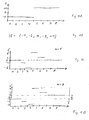
- 1A shows an example of the gray values b of pixels 1 to 8 of a linear array.
- the gray values take here as an example only the values -1 for pixels 1 to 4 and the values +1 for pixels 5 to 8.
- 1B shows the kernel G for this one-dimensional case.
- the spatially constant parts DC parts
- the filter used is similar to that which can also be used so-called Laplace filter, the Laplace operator replicates.
- the Laplace filter is usually used for this used to set zeros in the second derivative of an image search.
- K also appears as the gain factor for high-frequency spatial image components.
- DCo and thus also the compression K are thus determined by m.
- the central coefficient m must always be chosen such that is.
- the sum of all g ij must be really greater than 0.
- m would then be ⁇ 72 or m> 72.
- the scene shown is evenly adapted to a medium scene brightness, which corresponds to an infinite compression factor.
- the compression factor K would only be 1.5.
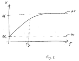
- FIG. 1D shows the amplitude of the gain V for the spatial frequencies f as graph 16.
- Graph 16 converges against the high frequency gain H.
- dashed line 14 is indicated.
- the cut-off frequency is designated by f g in FIG. 2.
- the cutoff frequency is the frequency that is amplified with approximately half the maximum gain.
- the cut-off frequency f g depends on the size (n, see above) of the kernel G of the high-pass filter, which is also called the kernel size. The larger the kernel, i.e. n, the higher the cut-off frequency, which leads to improved image fidelity in the case of medium structures or contrast differences that are not increased too much.
- a kernel size of 15x15 to 65x65, corresponding to n 7 to 32, has proven to be suitable.
- CCIR Comotti Consultatif International des Radio Communications
- the full picture is made up of the fields composed.
- the fields result in the so-called "Interlace” method.
- the images are "interlaced” read out, d. H. first all even lines read out, then all odd, etc. On this Way, despite a relatively low frame rate (25 frames / sec. With the CCIR standard) the flickering of the image be kept low on the monitor.
- the processing power required is from today not technically feasible.
- the Image data through the filter G in the processing chain Delayed at least the duration of n image lines because Calculation of a corrected pixel also the n subsequent lines of the picture are required and can therefore be waited for have to.
- the content of the image before First filtered with a high pass filter local structures with small contrast differences received, however, to weaken large contrast differences.
- the High pass filter has a non-vanishing Amplification for low-frequency and constant image components, thus large areas with very different Brightness and temperature values are not completely adjusted become, but remain recognizable in their differences.
- the high pass filter is now not calculated directly, but instead realized by weighted subtraction of an image that the uncorrected image content B by low-pass filtering won. This image obtained is as follows Called correction mask.
- a Gaussian low-pass filter takes place analogously to the kernel G according to equation (5), with the exception that the central element does not assume a special position, but is formed in the same way as the other elements.
- An example of a kernel G T of a low pass filter is
- Such a low-pass filter effects a weighted averaging of the values around a pixel.
- the weighting factor ⁇ is a positive number between 0 and 1, the meaning of which is clear from FIG. 3.
- FIG. 3 shows the transfer function of a low-pass filter in Combination with weighted subtraction as a function of spatial frequency f.
- the individual parts of the Fig. 3 always shows the amplitude V of the gain as a function of spatial frequencies f shown.
- 3B shows one Low pass filter, which is only the smallest frequency transmits unadulterated and attenuates all higher frequencies.
- the minus sign ("-") on the left 3B indicates the subtraction of the low-pass filter according to 3B from the identity according to FIG. 3A.
- the weighting factor ⁇ and the compression K are thus related.
- ⁇ determines the compression or ⁇ results from a desired compression.
- a low-pass filter requires the same computing effort as a high-pass filter.
- the replacement of a high-pass filter by the weighted subtraction of a low-pass filter G T thus does not yet lead to the desired reduction in computing effort.
- correction mask B K is calculated at most for every second image or field of an image sequence. This is possible without any noteworthy distortion of the image, since moving images may change from image to image in smaller spatial structures (correspondingly high spatial frequencies), but larger structures generally only change slightly from one image to the next. This is especially true when the movement within the image is small compared to the kernel size of the low pass filter G T.
- the calculated correction mask B K can thus also be used to correct subsequent images.
- the correction mask B K is therefore not calculated in real time, but asynchronously.
- a calculation of the correction mask B K has proven itself approximately 8 to 15 times per second. This reduces the computing power by a factor of four.
- the method according to the invention can be used with most cameras can be easily integrated into existing hardware.
- Fig. 4 shows the schematic structure and the coupling of the various components of the image processing hardware usual camera.
- the image data captured by the camera are stored in a memory 18 with that from the camera supported memory depth.
- a memory depth 14 bits for the camera or detector data accepted.
- To different To compensate for the sensitivity of the camera's pixels becomes a Image usually of a pixel-wise offset and Subject to gain correction (see e.g. DE 43 05 251 C1). "Gain” denotes the gain.
- Such a correction is referred to as a two-point correction, since it corrects both the position the sensitivity curve of the pixel (offset) as well as the Slope of the sensitivity curve of the pixel (gain) changed.
- the whole procedure is also called NUC correction (Non-Uniformity-Correction).
- the NUC correction is carried out in such a way that each pixel with multiplied by a stored NUC gain coefficient 24 becomes.
- a NUC offset coefficient image 20, 22 added to the uncorrected image data 18. This will make the Offset correction causes.
- the result is corrected Image data 26.
- these now have a dynamic of 16 bits, since both the addition and the Multiplication can lead to an increase in the values.
- 8 bits are selected from the 16 bits to this Display part of the 16 bit on a monitor. This is represented schematically by the 8-bit memory 30.
- the high-pass filter can be easily integrated into this hardware.
- the uncorrected image data 32 are subjected to low-pass filtering 34.
- This results in the correction mask B K which is then multiplied by the weighting factor ⁇ mentioned above.
- the result is subtracted from the offset correction coefficients 20 to obtain the actually used offset coefficients 22. Since the offset coefficients 22 are added to the uncorrected image data by the existing hardware, this effectively leads to a weighted subtraction of the correction mask B K.
- the calculation of the correction mask B K can be carried out by utilizing symmetries of the low-pass filter G T and by selecting the filter coefficients described above (see, for example, equation (8)) with the aid of simple vector operations.
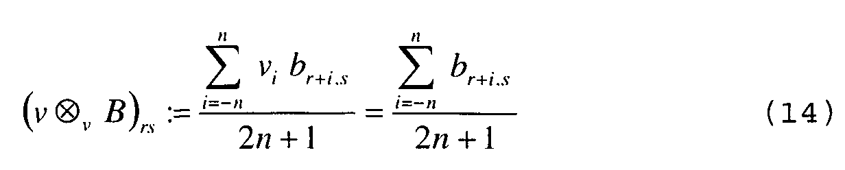
- the folding of the image B with a horizontal vector ( h ⁇ h B ) is defined component by component by:
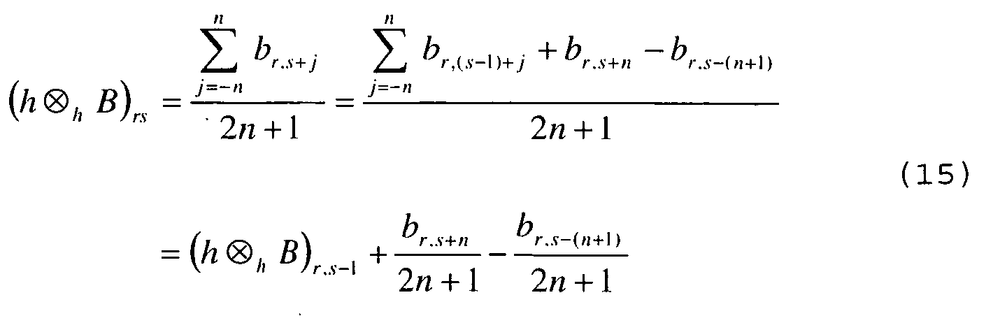
- a still further reduction in computing power can e.g. B. can be achieved based on the following relationships: and or analogous relationships for components neighboring in other directions.
- the directly adjacent components of the matrix to be folded can be used to calculate a component of the horizontally or vertically folded matrix.
- This method basically reduces the number of operations for the calculation of the correction mask B K per pixel to 8 operations, namely two additions for each of the four one-dimensional folds. This number is also independent of the filter kernel size.
- Suitable signal processors are e.g. B. so-called digital Signal processors (DSP).
- DSP digital Signal processors
- the method according to the invention is not only for Thermal imaging devices or thermal images, but for each type of Suitable for images.
Landscapes
- Engineering & Computer Science (AREA)
- Physics & Mathematics (AREA)
- General Physics & Mathematics (AREA)
- Theoretical Computer Science (AREA)
- Multimedia (AREA)
- Signal Processing (AREA)
- Image Processing (AREA)
- Closed-Circuit Television Systems (AREA)
Abstract
Description
- Fig. 1
- die Wirkung eines Hochpassfilters zweiter Ordnung;
- Fig. 2
- die Amplitude der Verstärkung V für die räumlichen Frequenzen f für einen Hochpassfilter zweiter Ordnung als Graph;
- Fig. 3
- die Übertragungsfunktion eines Tiefpassfilters in Kombination mit einer gewichteten Subtraktion als Funktion der räumlichen Frequenz f; und
- Fig. 4
- den schematischen Aufbau und die Kopplung der verschiedenen Komponenten der Bildverarbeitungs-Hardware einer üblichen Kamera.






Claims (6)
- Verfahren zum Darstellen einer Bildfolge mit großen Kontrasten bzw. mit einem hohen Dynamikbereich in den einzelnen Bildern mit hoher Auflösung über den gesamten Dynamikbereich auf einem Darstellungsmedium mit begrenzter Dynamik,a) wobei der Inhalt jedes Bilds (18) vor der Darstellung mit einem Hochpassfilter gefiltert wird;b) wobei der Hochpassfilter derart gewählt wird, dass er eine nicht verschwindende Verstärkung (DCo) für niederfrequente und konstante Bildanteile aufweist;c) wobei der Hochpassfilter durch gewichtete Subtraktion eines Bilds realisiert wird, das aus dem unkorrigierten Bildinhalt (18) durch Tiefpassfilterung (34) gewonnen wurde (Korrekturmaske) ;
dadurch gekennzeichnet,d) dass die Korrekturmaske höchstens für jedes zweite Bild der Bildfolge berechnet wird;e) dass zu jedem unkorrigierten Bild (18) ein Offset-Bild (20) zur Offset-Korrektur addiert bzw. subtrahiert wird; undf) dass die gewichtete Subtraktion der Korrekturmaske dadurch erfolgt, dass die Korrekturmaske vom Offset-Bild (20) gewichtet subtrahiert bzw. zum Offset-Bild (20) gewichtet addiert wird. - Verfahren zum Darstellen einer Bildfolge mit großen Kontrasten bzw. mit einem hohen Dynamikbereich in den einzelnen Bildern mit hoher Auflösung über den gesamten Dynamikbereich auf einem Darstellungsmedium mit begrenzter Dynamik,a) wobei der Inhalt des Bilds (18) vor der Darstellung mit einem Hochpassfilter gefiltert wird;b) wobei der Hochpassfilter derart gewählt wird, dass er eine nicht verschwindende Verstärkung (DCo) für niederfrequente und konstante Bildanteile aufweist;c) dass der Hochpassfilter durch gewichtete Subtraktion eines Bilds realisiert wird, das aus dem unkorrigierten Bildinhalt (18) durch Tiefpassfilterung (34) gewonnen wurde (Korrekturmaske) ;
dadurch gekennzeichnet,d) dass die Korrekturmaske höchstens für jedes zweite Bild einer Bildfolge berechnet wird; unde) dass die Korrekturmaske in der folgenden Weise berechnet wird:i) Faltung der unkorrigierten Bilddaten mit einem horizontalen Vektor h = (h 1, ..., hn ) = (1, ..., 1), der ausschließlich mit Einsen besetzt ist;ii) Faltung des Ergebnisses mit einem vertikalen Vektor v = (v 1, ..., vn )=(1, ..., 1), der ebenfalls ausschließlich mit Einsen besetzt ist;iii) erneute Faltung des Ergebnisses mit dem horizontalen Vektor h; undiv) erneute Faltung des Ergebnisses mit dem vertikalen Vektor v. - Verfahren nach dem vorhergehenden Anspruch,
dadurch gekennzeichnet, dass zur Berechnung einer Komponente der horizontal oder vertikal gefalteten Matrix die unmittelbar benachbarten Komponenten der zu faltenden Matrix genutzt werden. - Verfahren nach einem der vorhergehenden Ansprüche,
dadurch gekennzeichnet, dass zur Berechnung der Korrekturmaske benachbarte Pixel zusammengefasst werden oder unberücksichtigt bleiben. - Anordnung zum Darstellen einer Bildfolge mit großen Kontrasten bzw. mit einem hohen Dynamikbereich in den einzelnen Bildern mit hoher Auflösung über den gesamten Dynamikbereich auf einem Darstellungsmedium mit begrenzter Dynamik,a) mit einem Hochpassfilter zum Filtern des Inhalts jedes Bilds (18) vor der Darstellung;b) wobei der Hochpassfilter eine nicht verschwindende Verstärkung (DCo) für niederfrequente und konstante Bildanteile aufweist;c) mit Mitteln zum Realisieren des Hochpassfilters durch gewichtete Subtraktion eines Bilds, das aus dem unkorrigierten Bildinhalt (18) durch Tiefpassfilterung (34) gewonnen wurde (Korrekturmaske) ;
gekennzeichnet durchd) Mittel zum Steuern der Berechnung der Korrekturmaske derart, dass die Korrekturmaske höchstens für jedes zweite Bild der Bildfolge berechnet wird;e) Mittel zum Addieren bzw. Subtrahieren eines Offset-Bildes (20) zur Offset-Korrektur jedes unkorrigierten Bildes (18); und durchf) Mittel zum Durchführen der gewichteten Subtraktion der Korrekturmaske derart, dass die Korrekturmaske vom Offset-Bild (20) gewichtet subtrahiert bzw. zum Offset-Bild (20) gewichtet addiert wird. - Anordnung zum Darstellen einer Bildfolge mit großen Kontrasten bzw. mit einem hohen Dynamikbereich in den einzelnen Bildern mit hoher Auflösung über den gesamten Dynamikbereich auf einem Darstellungsmedium mit begrenzter Dynamik,a) mit einem Hochpassfilter zum Filtern des Inhalts jedes Bilds (18) vor der Darstellung;b) wobei der Hochpassfilter eine nicht verschwindende Verstärkung (DCo) für niederfrequente und konstante Bildanteile aufweist;c) mit Mitteln zum Realisieren des Hochpassfilters durch gewichtete Subtraktion eines Bilds, das aus dem unkorrigierten Bildinhalt (18) durch Tiefpassfilterung (34) gewonnen wurde (Korrekturmaske) ;
gekennzeichnet durchd) Mittel zum Steuern der Berechnung der Korrekturmaske derart, dass die Korrekturmaske höchstens für jedes zweite Bild der Bildfolge berechnet wird;e) Mittel zum Berechnen der Korrekturmaske in der folgenden Weise:i) Faltung der unkorrigierten Bilddaten mit einem horizontalen Vektor h = (h 1, ..., hn ) = (1, ..., 1), der ausschließlich mit Einsen besetzt ist;ii) Faltung des Ergebnisses mit einem vertikalen Vektor v=(v 1,...,vn )=(1,...,1), der ebenfalls ausschließlich mit Einsen besetzt ist;iii) erneute Faltung des Ergebnisses mit dem horizontalen Vektor h; undiv) erneute Faltung des Ergebnisses mit dem vertikalen Vektor v.
Applications Claiming Priority (2)
| Application Number | Priority Date | Filing Date | Title |
|---|---|---|---|
| DE10162422 | 2001-12-18 | ||
| DE10162422A DE10162422A1 (de) | 2001-12-18 | 2001-12-18 | Visualisierung von extremen Kontrastunterschieden bei Kamerasystemen |
Publications (2)
| Publication Number | Publication Date |
|---|---|
| EP1326431A2 true EP1326431A2 (de) | 2003-07-09 |
| EP1326431A3 EP1326431A3 (de) | 2009-08-19 |
Family
ID=7709826
Family Applications (1)
| Application Number | Title | Priority Date | Filing Date |
|---|---|---|---|
| EP02028415A Withdrawn EP1326431A3 (de) | 2001-12-18 | 2002-12-18 | Visualisierung von extremen Kontrastunterschieden bei Kamerasystemen |
Country Status (2)
| Country | Link |
|---|---|
| EP (1) | EP1326431A3 (de) |
| DE (1) | DE10162422A1 (de) |
Families Citing this family (1)
| Publication number | Priority date | Publication date | Assignee | Title |
|---|---|---|---|---|
| CN103413285A (zh) * | 2013-08-02 | 2013-11-27 | 北京工业大学 | 基于样本预测的hdr和hr图像重建方法 |
Family Cites Families (3)
| Publication number | Priority date | Publication date | Assignee | Title |
|---|---|---|---|---|
| FR2445536B1 (fr) * | 1978-12-26 | 1989-12-22 | Fuji Photo Film Co Ltd | Procede et appareil pour traiter une image radiographique |
| US4903205A (en) * | 1985-10-15 | 1990-02-20 | Fuji Photo Film Co. Ltd. | Method and apparatus for displaying radiation image, and method and apparatus for calculating unsharp mask signal used for the same |
| DE19713648C2 (de) * | 1997-04-02 | 1999-06-24 | Stein Werner Ritter Von | Verfahren zur elektronischen Reduktion des Hell/Dunkelkontrastes von Videobildern bereits bei der Aufnahme |
-
2001
- 2001-12-18 DE DE10162422A patent/DE10162422A1/de not_active Ceased
-
2002
- 2002-12-18 EP EP02028415A patent/EP1326431A3/de not_active Withdrawn
Non-Patent Citations (1)
| Title |
|---|
| None * |
Also Published As
| Publication number | Publication date |
|---|---|
| EP1326431A3 (de) | 2009-08-19 |
| DE10162422A1 (de) | 2003-07-17 |
Similar Documents
| Publication | Publication Date | Title |
|---|---|---|
| DE602005004694T2 (de) | Verfahren und Vorrichtung für lokal adaptive Bildverarbeitungsfilter | |
| DE69411470T2 (de) | Methode und Vorrichtung zur Verbesserung der Schärfe einer einem kontinuierlichem Zoom unterworfenen Bildfolge | |
| DE60215726T2 (de) | Detektion und Korrektur von schlechten Pixeln in einer Bildaufnahmevorrichtung | |
| DE69120661T2 (de) | Bildkompression mit farbinterpolation für ein bildaufnahmesystem mit nur einem bildaufnehmer | |
| DE69812800T2 (de) | Verfahren und Gerät zur Bildverbesserung | |
| DE2938130C3 (de) | System zur Störungs- bzw. Rauschverminderung in einem Bildsignal | |
| DE69132203T2 (de) | System und Verfahren zur Echtzeit-Mischung von Videobildern aus mehreren Quellen | |
| DE69032177T2 (de) | Kodierungsgerät | |
| DE60020795T2 (de) | Echtzeitmodellierung des Verhaltens menschlicher Sehvermögenssysteme | |
| DE69028946T2 (de) | Verfahren zur adaptiven Schärfung elektronischer Bilder | |
| DE2937282C2 (de) | ||
| DE112016001040T5 (de) | Verfahren und System zur Echtzeit-Rauschbeseitung und -Bildverbesserung von Bildern mit hohem Dynamikumfang | |
| DE69318377T2 (de) | Methode und Vorrichtung zur Erhöhung der Bildfrequenz | |
| DE69522376T2 (de) | Verfahren und Vorrichtung zur graphischen Verarbeitung | |
| DE2636209B2 (de) | Vorrichtung zur Kontrastverbesserung eines Bildes | |
| DE602004012125T2 (de) | Robuste rekursive hüllenoperatoren für die schnelle verarbeitung von bildern des retinex-typs | |
| DE102005025629A1 (de) | Bildverarbeitungsverfahren zur Reduzierung von Blocking-Artefakten | |
| DE69424923T2 (de) | Verfahren und Anordnung zur Bearbeitung eines dekodierten Bildsignals mit Verzerrung | |
| DE69626475T2 (de) | Verfahren zur Korrektur von Bewegungsschätzung in Bildern mit periodischen Strukturen | |
| DE60303614T2 (de) | Verfahren zur bildskalierung | |
| DE102006038646A1 (de) | Bildverarbeitungsvorrichtung für Farb-Bilddaten und Verfahren zur Bildverarbeitung von Farb-Bilddaten | |
| DE10055862C2 (de) | Verfahren zum Ausgleich von technologisch bedingten Inhomogenitäten in den Einzelelementen eines Detektors, der zur Bildaufnahme eingesetzt wird | |
| DE10162422A1 (de) | Visualisierung von extremen Kontrastunterschieden bei Kamerasystemen | |
| DE69602535T2 (de) | Verfahren zur verarbeitung einer numerischen verrauschten quellbildsequenz | |
| DE69514022T2 (de) | Quantizierungsschaltung |
Legal Events
| Date | Code | Title | Description |
|---|---|---|---|
| PUAI | Public reference made under article 153(3) epc to a published international application that has entered the european phase |
Free format text: ORIGINAL CODE: 0009012 |
|
| AK | Designated contracting states |
Designated state(s): AT BE BG CH CY CZ DE DK EE ES FI FR GB GR IE IT LI LU MC NL PT SE SI SK TR |
|
| AX | Request for extension of the european patent |
Extension state: AL LT LV MK RO |
|
| RAP1 | Party data changed (applicant data changed or rights of an application transferred) |
Owner name: CARL ZEISS OPTRONICS GMBH |
|
| PUAL | Search report despatched |
Free format text: ORIGINAL CODE: 0009013 |
|
| RIC1 | Information provided on ipc code assigned before grant |
Ipc: G06T 5/20 20060101ALI20090708BHEP Ipc: H04N 5/217 20060101AFI20030329BHEP |
|
| AK | Designated contracting states |
Kind code of ref document: A3 Designated state(s): AT BE BG CH CY CZ DE DK EE ES FI FR GB GR IE IT LI LU MC NL PT SE SI SK TR |
|
| AX | Request for extension of the european patent |
Extension state: AL LT LV MK RO |
|
| 17P | Request for examination filed |
Effective date: 20091112 |
|
| 17Q | First examination report despatched |
Effective date: 20100215 |
|
| AKX | Designation fees paid |
Designated state(s): DE FR GB |
|
| STAA | Information on the status of an ep patent application or granted ep patent |
Free format text: STATUS: EXAMINATION IS IN PROGRESS |
|
| STAA | Information on the status of an ep patent application or granted ep patent |
Free format text: STATUS: THE APPLICATION IS DEEMED TO BE WITHDRAWN |
|
| 18D | Application deemed to be withdrawn |
Effective date: 20180703 |