EP1326358A1 - Scaling of Viterbi decoding based on channel and location information - Google Patents
Scaling of Viterbi decoding based on channel and location information Download PDFInfo
- Publication number
- EP1326358A1 EP1326358A1 EP02090416A EP02090416A EP1326358A1 EP 1326358 A1 EP1326358 A1 EP 1326358A1 EP 02090416 A EP02090416 A EP 02090416A EP 02090416 A EP02090416 A EP 02090416A EP 1326358 A1 EP1326358 A1 EP 1326358A1
- Authority
- EP
- European Patent Office
- Prior art keywords
- point
- constellation
- signal
- quantized
- metric
- Prior art date
- Legal status (The legal status is an assumption and is not a legal conclusion. Google has not performed a legal analysis and makes no representation as to the accuracy of the status listed.)
- Granted
Links
- 238000000034 method Methods 0.000 claims abstract description 20
- 230000007704 transition Effects 0.000 description 21
- 238000010586 diagram Methods 0.000 description 13
- 239000000654 additive Substances 0.000 description 3
- 230000000996 additive effect Effects 0.000 description 3
- 230000006872 improvement Effects 0.000 description 3
- 230000005540 biological transmission Effects 0.000 description 2
- 238000010276 construction Methods 0.000 description 2
- 238000013461 design Methods 0.000 description 2
- 230000007246 mechanism Effects 0.000 description 2
- 230000011664 signaling Effects 0.000 description 2
- 238000007476 Maximum Likelihood Methods 0.000 description 1
- 238000013459 approach Methods 0.000 description 1
- 238000004364 calculation method Methods 0.000 description 1
- 238000004891 communication Methods 0.000 description 1
- 238000012937 correction Methods 0.000 description 1
- 230000001419 dependent effect Effects 0.000 description 1
- 238000005315 distribution function Methods 0.000 description 1
- 230000036039 immunity Effects 0.000 description 1
- 230000004048 modification Effects 0.000 description 1
- 238000012986 modification Methods 0.000 description 1
- 230000008569 process Effects 0.000 description 1
- 230000005236 sound signal Effects 0.000 description 1
- 230000003245 working effect Effects 0.000 description 1
Images








Classifications
-
- H—ELECTRICITY
- H04—ELECTRIC COMMUNICATION TECHNIQUE
- H04L—TRANSMISSION OF DIGITAL INFORMATION, e.g. TELEGRAPHIC COMMUNICATION
- H04L27/00—Modulated-carrier systems
- H04L27/32—Carrier systems characterised by combinations of two or more of the types covered by groups H04L27/02, H04L27/10, H04L27/18 or H04L27/26
- H04L27/34—Amplitude- and phase-modulated carrier systems, e.g. quadrature-amplitude modulated carrier systems
-
- H—ELECTRICITY
- H03—ELECTRONIC CIRCUITRY
- H03M—CODING; DECODING; CODE CONVERSION IN GENERAL
- H03M13/00—Coding, decoding or code conversion, for error detection or error correction; Coding theory basic assumptions; Coding bounds; Error probability evaluation methods; Channel models; Simulation or testing of codes
- H03M13/37—Decoding methods or techniques, not specific to the particular type of coding provided for in groups H03M13/03 - H03M13/35
- H03M13/3723—Decoding methods or techniques, not specific to the particular type of coding provided for in groups H03M13/03 - H03M13/35 using means or methods for the initialisation of the decoder
-
- H—ELECTRICITY
- H03—ELECTRONIC CIRCUITRY
- H03M—CODING; DECODING; CODE CONVERSION IN GENERAL
- H03M13/00—Coding, decoding or code conversion, for error detection or error correction; Coding theory basic assumptions; Coding bounds; Error probability evaluation methods; Channel models; Simulation or testing of codes
- H03M13/37—Decoding methods or techniques, not specific to the particular type of coding provided for in groups H03M13/03 - H03M13/35
- H03M13/39—Sequence estimation, i.e. using statistical methods for the reconstruction of the original codes
- H03M13/41—Sequence estimation, i.e. using statistical methods for the reconstruction of the original codes using the Viterbi algorithm or Viterbi processors
-
- H—ELECTRICITY
- H03—ELECTRONIC CIRCUITRY
- H03M—CODING; DECODING; CODE CONVERSION IN GENERAL
- H03M13/00—Coding, decoding or code conversion, for error detection or error correction; Coding theory basic assumptions; Coding bounds; Error probability evaluation methods; Channel models; Simulation or testing of codes
- H03M13/37—Decoding methods or techniques, not specific to the particular type of coding provided for in groups H03M13/03 - H03M13/35
- H03M13/39—Sequence estimation, i.e. using statistical methods for the reconstruction of the original codes
- H03M13/41—Sequence estimation, i.e. using statistical methods for the reconstruction of the original codes using the Viterbi algorithm or Viterbi processors
- H03M13/4107—Sequence estimation, i.e. using statistical methods for the reconstruction of the original codes using the Viterbi algorithm or Viterbi processors implementing add, compare, select [ACS] operations
-
- H—ELECTRICITY
- H03—ELECTRONIC CIRCUITRY
- H03M—CODING; DECODING; CODE CONVERSION IN GENERAL
- H03M13/00—Coding, decoding or code conversion, for error detection or error correction; Coding theory basic assumptions; Coding bounds; Error probability evaluation methods; Channel models; Simulation or testing of codes
- H03M13/65—Purpose and implementation aspects
- H03M13/6577—Representation or format of variables, register sizes or word-lengths and quantization
-
- H—ELECTRICITY
- H03—ELECTRONIC CIRCUITRY
- H03M—CODING; DECODING; CODE CONVERSION IN GENERAL
- H03M13/00—Coding, decoding or code conversion, for error detection or error correction; Coding theory basic assumptions; Coding bounds; Error probability evaluation methods; Channel models; Simulation or testing of codes
- H03M13/65—Purpose and implementation aspects
- H03M13/6577—Representation or format of variables, register sizes or word-lengths and quantization
- H03M13/658—Scaling by multiplication or division
-
- H—ELECTRICITY
- H04—ELECTRIC COMMUNICATION TECHNIQUE
- H04L—TRANSMISSION OF DIGITAL INFORMATION, e.g. TELEGRAPHIC COMMUNICATION
- H04L1/00—Arrangements for detecting or preventing errors in the information received
- H04L1/004—Arrangements for detecting or preventing errors in the information received by using forward error control
- H04L1/0045—Arrangements at the receiver end
- H04L1/0054—Maximum-likelihood or sequential decoding, e.g. Viterbi, Fano, ZJ algorithms
-
- H—ELECTRICITY
- H04—ELECTRIC COMMUNICATION TECHNIQUE
- H04L—TRANSMISSION OF DIGITAL INFORMATION, e.g. TELEGRAPHIC COMMUNICATION
- H04L25/00—Baseband systems
- H04L25/02—Details ; arrangements for supplying electrical power along data transmission lines
- H04L25/06—DC level restoring means; Bias distortion correction ; Decision circuits providing symbol by symbol detection
- H04L25/067—DC level restoring means; Bias distortion correction ; Decision circuits providing symbol by symbol detection providing soft decisions, i.e. decisions together with an estimate of reliability
Definitions
- the invention relates to methods used to decode convolutionally coded data, and in particular embodiments to methods of improving Viterbi decoding.
- Viterbi decoding is commonly used as a technique for recovering the most likely sequence of information bits that have been encoded with convolutional coding and degraded by transmission through a communication channel.
- a Viterbi decoder uses a trellis diagram representation of the convolutional code, to model the code as a set of states and branches. At a time n, the code occupies state S n . The branches of the trellis diagram denote allowable transitions between states.
- a metric is associated with each state and each transition between states (branch). The metric reflects the likelihood of the code occupying that state at that time instant given the received bits.
- a higher metric value implies that a state is less likely at that time instant, although lower values for less likely states equivalently may be used.
- the metric for each possible next state at time n is computed by the three step Viterbi algorithm.
- the path metrics which represent the likelihood of entering a state from an allowable path, are added.
- the path metrics for various paths are compared and the lowest metric is then selected as the most probable path.
- a Viterbi decoder can determine the most likely sequence of information bits by tracing the sequence of branches, having the maximum likelihood, leading to a particular state.
- Viterbi decoding while simpler than iterative forms of decoding such as MAP (Maximum A Posteriori) or soft Viterbi decoding, in general does not perform as well. There is therefore a need in the art for improved Viterbi decoding which is less complex than the iterative forms of decoding.
- the disclosure illustrates a method for taking into account the geometry of a signal constellation, which makes some bits more error prone than others.
- the chances of a bit being in error are dependent on the location of the bit with respect to other bits in the constellation. If adjacent constellation points have the same bit value in a particular location, they are less likely to be in error than if the constellation had adjacent bits with opposite values. More of a deviation is necessary to create an error in the first case, where adjacent symbol constellation points have the same value. A given amount of noise deviation in the first case may not create an error, whereas in the second case the exact same amount of noise deviation may create an error. This fact may be reflected in the branch metrics used by a Viterbi decoder, resulting in an improvement in decoder performance.
- the signal to noise ratio (SNR) of a signal being received is used, in addition to information about the point location within the constellation, to scale the branch metrics so that the decoding more accurately models the actual channel performance.
- SNR signal to noise ratio
- further scaling of the branch metrics, according to the SNR may further enhance decoding capability.
- a method for Viterbi decoding is disclosed.
- a sampled signal is received.
- a hard decision is made on which constellation point the sampled signal represents.
- a scaling factor (k) is determined corresponding to the hard decision point, and the scaling factor (k) and the hard decision is provided to a Viterbi decoder
- a method of signal decoding is disclosed.
- a received signal is accepted.
- the received signal is quantized to a point in a signal constellation plane, to provide a quantized point.
- a hard decision is made as to which constellation point the quantized point represents.
- Scaling factors (ks) associated with each constellation point are determined.
- the scaling factors and hard decision point are used to determine decoder metrics and decoder metrics and quantized points are provided to a Viterbi decoder.
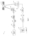
- Figure 1 is a graphical illustration of an environment in which embodiments of the present invention may operate.
- the environment illustrated at 101 is a data distribution system, such as may be found in a cable television distribution system.
- Figure 1 data is provided to the transmission system by an information source 103.
- the information source displayed in Figure 1 may be considered to be a cable television system head end, which provides video data to end users.
- Embodiments of the invention are not limited to any particular type of information source and any other data source could be equivalently substituted.
- a formatter 105 accepts data from information source 103.
- the data provided by information source 103 may comprise analog or digital signals such as (but not limited to) video signals, audio signals, and data signals.
- Formatter block 105 formats received data into an appropriate form, such as the data illustrated at 107.
- the formatted data 107 is then provided to a channel encoder 109.
- Channel encoder 109 encodes the formatted data 107 provided to it.
- the channel encoder 109 may provide an encoding for improving performance over the channel.
- Channel encoder 109 provides encoded data to a transmitter 111.
- Transmitter 111 transmits the encoded data provided by channel encoder 109, for example, using an antenna 113.
- the signal transmitted from antenna 113 is accepted by a relay satellite 115 and then retransmitted to a terrestrial receiving antenna, such as earth station antenna 117.
- Earth station antenna 117 collects the satellite signal and provides the collected signal to a receiver 119.
- the receiver 119 amplifies and demodulates/detects the signal as appropriate and provides the detected signal to a decoder 121.
- Decoder 121 will, essentially, reverse the process of the channel encoder 109 and recreate the data 123, which should represent a good estimate of the data 107 that had been broadcast.
- the decoder 121 may use Forward Error Correction (FEC), in order to correct errors in the received signal.
- FEC Forward Error Correction
- the data 123 provided by the decoder are then provided to a formatting unit 125, which prepares the received data for use by an information sink, such as the television illustrated at 127.
- FIG 2 is a graphical illustration of a 16 QAM signal constellation.
- a 16 QAM signal constellation comprises 16 points which are labeled with four bits. For the sake of convenience two bits are used to label the X dimension of the constellation and an additional two bits are used to label the Y dimension of the constellation. In the X dimension points are labeled as 00, 01, 11, and 10 as illustrated at 201. The two bits 201 comprise the two most significant bits which define each point. The points in the Y dimension may be similarly labeled as shown at 203. Accordingly, for a point 205 a label is generated by reading the X dimension bits (11) first and the Y dimension bits (01) second. Point 205 thereby is assigned a value of 1101, as illustrated in Figure 2.
- Figure 3 is a graphical illustration of hard decision decoding on two subchannels having different signal to noise (SNR) ratios.
- SNR signal to noise
- the signal to noise ratio is 13 dB (decibels).
- the signal to noise ratio is 0 dB.
- the point x 1 received on subchannel 301 is illustrated at 305.
- the point x 2 received on subchannel 302, is illustrated at 307.
- point 305 in subchannel 301 falls into decision region 309, marked by the crosshatched area in Figure 3, and accordingly would be assigned a value of 00.
- received point 307 in subchannel 302, which falls in decision region 311, would be assigned the value of 01.
- Equation 1 implies that the Hamming distance D between the received point x in the most significant bit (MSB) position and zero is equal to 0.
- Equation 2 also implies that the Hamming distance between the received point x and a least significant bit (LSB) of 0 is also 0.
- Equation 3 implies that the Hamming distance between the received point x and an MSB of 1 is equal to 1.
- Equation 4 implies that the Hamming distance between the received point x and an LSB of 1 is equal to 1. This type of distance metric in which only the values of 1 and 0 are permitted, is referred to as Hamming metric.
- a Hamming metric, taken between two quantities, is 0 if the quantities are equal, and 1 if they are not equal.
- the equations may also equivalently be considered to be distances, with a "0" corresponding to zero distance between the postulated point and the hard decision and a "1" representing a non-zero distance between the postulated point and the hard decision point.
- Equation 5 implies that the distance between the received point x, and an MSB of 0 is equal to 0 because the hard decision is that the MSB is 0.
- Equation 7 implies that the distance between an MSB of 1 and the hard decision is equal to a 1 because the hard decision indicates that the MSB is not equal to a 1.
- equation 6 implies that the distance between the hard decision LSB and 0 is equal to 1 (i.e. a non-zero distance).
- Equation 8 implies that the distance between the received LSB and 1 is equal to 0 because the hard decision assigns a value of 1 to the LSB position.
- the metric is 0 if the hard decision matches the postulated point in metric equation and 1 if it does not. In such a manner the metrics are assigned a value of 0 or 1.
- a problem with the Hamming metric approach is that the value of the metric equation is either 0 or 1 independent of the received signal strength. For the examples shown at subchannel 301, however, the likelihood of the hard decision being correct is greater than the example shown at subchannel 302. This is because in subchannel 301 the signal to noise ratio is 13 dB and the signal is much stronger relative to noise than that present in subchanne! 302, and therefore more likely to be a correct value. In other words the stronger the signal relative to noise the more likely that it is correct.
- a Hamming metric however, has no mechanism for taking the signal to noise ratio (SNR) of the channel into account. Accordingly, the Hamming metric scheme needs to be modified in order to take into account the SNR present in the channel.
- SNR signal to noise ratio
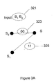
- Figure 3A is a graphical illustration of a portion of a trellis diagram illustrating a Hamming metric.
- state S may be entered from state S 0 by receiving an input bit sequence of 00 (323).
- State S may also be entered from state S 1 by receiving an input bit sequence 11 (325). Accordingly, computing the Hamming metric is straight forward.
- the difference between the input sequence received 321 (comprising bits B 1 and B 0 ) is examined on a bit by bit basis and compared to the input sequences 323 and 325, which are necessary to cause a transition into state S.
- Each place sequence in which sequence 321 differs from sequence 323 is assigned a value of 1.
- the metric for the transition from S 0 into S is equal to a 0 if input bit B, is a 0 and input bit B 0 is a 0.
- the value of the metric is equal to a 1 if only one of the bits B 1 or B 0 is equal to 1.
- the value of the branch metric is equal to a 2 if both bits B 1 and B 0 are 1. The higher value for the branch metric the less likely that that transition has been taken.
- the difference between sequence 11, i.e. 325 and the input sequence 321 is computed. If input B 1 and B 0 are both 1s then the input sequence matches sequence 325 and the metric is 0.
- the branch metrics may be used in the add compare and select mechanism of the Viterbi algorithm.
- the adding distance method of calculating branch Hamming metrics is simple, other methods may yield better decoder performance. This is so because the Hamming metrics treat every bit error as equal likely as any other bit error.
- the Hamming metric method does not take into account that some bits may be more reliable than others. If information is available that some bits are more reliable than others, it may be exploited in order to improve decoder performance.
- Branch metrics in general represent the likelihood that a transition (i.e., branch) between states will be taken. Accordingly, the likelihood of a transition between multiple states is proportional to the product of the likelihoods of transitions linking the two end states. In other words, if a transition between a state A and a state C occurs and the most likely path between A and C is equal to A, B, C then the likelihood of transition between state A and state C is equal to the likelihood of transition between state A and state B times the likelihood of transition between state B and state C. This in essence is the reasoning behind the workings of a Viterbi decoder.
- probabilities within a Viterbi decoder are generally expressed in logarithmic (log) terms.
- the probabilities within a Viterbi decoder are expressed in logarithmic terms, in general, so that instead of having to multiply transition probabilities an equivalent operation of adding logarithms of transition probabilities may be utilized.
- Multiplication is a complex electronic operation and by substituting an addition operation, such as the addition of logarithmic probabilities, the speed of calculations can be improved.
- Equation 9 represents the log of the probability of receiving a bit in error.
- Q is a function, described later, which will be evaluated at the value where d is the distance between two constellation points and ⁇ is the standard deviation of the noise.
- AWGN Additive White Gaussian Noise
- the Q function is the area under the tail of a Gaussian distribution, the general form of which is illustrated in Figure 4.
- Figure 4 is a graph of noise distribution, for a signal channel having Additive White Gaussian Noise (AWGN), illustrating the "Q" function.
- the Gaussian probability distribution function is shown generally at 401.
- the Q function evaluated at a value, x, represents the probability that a random variable with Gaussian distribution is larger than x.
- the Q function which represents the probability that the AWGN is large enough to cause a bit error, is illustrated generally at 403.
- the Q function gives the likelihood that a noise signal having a value greater than point 405, which is the bit threshold of error, will be present and accordingly, will cause an error in the received bit. In other words, the noise, for values larger than point 405, is so strong as to cause a bit error when added to the transmitted point.
- Equation 9 implies that the signal to noise ratio of a channel can be used to scale the branch metrics of equations 1 through 8. Such a scaling is illustrated in Figure 5.
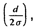
- the signal to noise ratio of a channel allows (d/2 ⁇ ) to be computed.
- the value of (d/2 ⁇ ) allows the computation of the value of log P as in equation 9.
- the value for log P can be quantified to a number of bits, which may be used to determine the scaling factor for the branch metrics under given signal to noise conditions.
- Figure 5 is a graphical illustration of decoding with channel information.
- equation 3 and 4 of Figure 3 have been altered to equations 3A and 4A in order to take into account channel SNR information.
- equation 3A the value of the branch metric has been increased to 4 indicating that receiving an MSB that is in error is less likely because of the strong signal being provided by the channel.
- Figure 6 is a graphical illustration of decoding with channel and location information.
- location information consider the received point 601 in the subchannel 302 diagram. If point 601 is received it will be assigned a value of 01, that is a hard decision is being made that point 613 was transmitted. Point 613 may actually be incorrect, having an error in one or both received bits. If the most significant bit of 601 is in error then 603 was most likely sent. If 601 had an error in the LSB then 605 was most likely sent. In contrast consider point 607 in subchannel 301. Point 607 is assigned a value of 00, that is a hard decision that point 615 was transmitted is made.
- Metric equation 4B's value of 4 indicates the likelihood that a mistake was made in the least significant bit being received (i.e., converting a "0" to a "1") is less than the likelihood of a bit error on subchannel 302, which has a maximum metric value of 1. This reflects that fact that the signal to noise ratio on the channel is 13 dB, which is much higher than it is for subchannel 302.
- the metric value for equation 3B is equal to 7 indicating both that the signal to noise ratio is higher in subchannel 301 than subchannel 302 and that in order to make an error in the most significant bit, the constellation point will deviate a greater distance than for an error in the least significant bit. This greater deviation to make a MSB error provides a greater noise immunity and hence the lessened likelihood of MSB error.
- the lower probability is reflected in the higher value of the metric, i.e. 7, as illustrated in Equation 3B.
- the higher value metrics indicate a cost of making an error. The cost is inversely proportionate to probability.
- Point 601 is received within decision region 617 and assigned the value of 01. So if an error in the most significant bit has occurred, then, most likely point 603 was transmitted. Points 603 and 613 are separated by a distance d. Similarly, if an error is made in the least significant bit, then the point interpreted as point 613 was most likely point 605 when transmitted. Points 605 and 613 are separated by a distance d.
- the distance associated with an error in the least significant bit is equal to a distance d.
- the received point interpreted as 615 was probably transmitted as point 611 and had been displaced by noise a distance of 2d in order to create the error.
- This type of location information may be exploited in order to weight the reliability of the received bits and the probability they are correct. Because the decisions being made are hard decisions, the Viterbi decoder only knows that a point received was given a value of 00 and nothing about where in the decision region 619 the point was located. Accordingly, the distance that will be used to compute the contribution of the location to the overall reliability of the received value is the distance from the transmitted point to the nearest edge of the decision region corresponding to the hard decision that was made.
- the log probability for the LSB is equal to the Log Q(d/2 ⁇ ).
- the log of P for the MSB is equal to the Log Q(3d/2 ⁇ ).
- the log probability may be used to scale the branch metrics. Therefore, as reflected in equation 4B, the metric for making an error on the least significant bit has a weight of 4. The metric for making an error on the most significant bit has a weight of 7 as illustrated in equation 3B.
- the location information and the signal strength information By using the location information and the signal strength information an additional 1 to 2 dB of decoding margin can be realized over the case where neither is used.
- the (d/2 ⁇ ) value for the channel may be calculated.
- the location information given by the construction of the signaling constellation, can be used by itself or in concert with the signal to noise ratio information in order to scale branch metrics.
- the d/2o portion of the equation represents the signal to noise ratio information and the k portion represents the location information.
- the various values of k can be precomputed and stored in a look-up table.
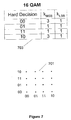
- Figure 7 is a graphic illustration of location information incorporated into an exemplary 16 QAM constellation.
- the exemplary QAM constellation is illustrated at 701.
- the corresponding computed k values are illustrated in look up table 703. That is for a hard decision of 00 the k MSB is 3 and the k LSB is 1. For a hard decision of 01 the k MSB is equal to 1 and the k LSB is equal to 1. For a hard decision of 11 k MSB is equal to 1 and k LSB is equal to 1. For a hard decision of 10, k MSB is equal to 3 and k LSB is equal to 1.
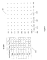
- Figure 8 is a graphic illustration of location information derived from an exemplary QAM constellation 801.
- the exemplary 64 QAM constellation is represented generally at 801.
- the various values for k are illustrated in table 803.
- values for k depend upon the bit position within the signal constellation, i.e. the location information, within the 64 QAM constellation 801. For example, if a hard decision is made that the received point is a 000, the weighting of the most significant bit, k MSB , is equal to 7. In order for the MSB of point 805 to be in error, instead of point 805 being the actual point transmitted, the nearest point, in which the MSB would be a 1 instead of 0, is point 809.
- the weight k 2sb is equal to 3. If a hard decision of 000 is received and if the second most significant bit is in error, then instead of point 805 being the point that was sent, point 807 was most likely sent.
- the k for the least significant bit of point 805 is equal to 1 because, if an error is made in the least significant bit, instead of point 805 being sent point 811 had most likely been sent. In such a way the metrics may be modified to reflect the position within the signal constellation, with the less likely errors are weighted more heavily than the more likely errors.
- the k values are assigned such that if for a point to be received in error an adjacent constellation point may have been transmitted, k is given a value of one. If the adjacent point has the same bit value and a point two constellation points away may have been transmitted to create the error, a weight of 3 is assigned, if two adjacent points have the same bit value but a point 3 constellation points away may have been transmitted to create the error, a weight of 5 is assigned, and so forth. In other words, for every additional constellation point that an error must traverse, a value of 2 is added to k.
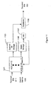
- Figure 9 is a block diagram, at a high level, of a Viterbi decoder using both channel SNR and location information.
- demapper 905 receives an SNR value 903 and received signal point 901.
- the demapper 905 computes the hard decision of the point received, as well as the branch metrics (which may be obtained from a look-up table), and provides them to a Viterbi decoder 907.
- the Viterbi decoder then decodes the hard decisions and provides the decoded bits 909.
- Figure 10 is a block diagram of the demapper 905 illustrated in Figure 9.
- the received signal 901 is accepted by a block 1001 which decides the value of the point that was received.
- block 1001 locates the point, which was received, within the constellation plane.
- the received point is then converted to bit values in block 1003.
- the location information scaling factors i.e. the k's, are determined in block 1005.
- an appropriate branch metrics look up table is constructed 1007.
- the metrics 1009, along with the received bits 1011, are then provided to the Viterbi decoder illustrated in Figure 11.
- Figure 11 is a block diagram of the Viterbi decoder illustrated in Figure 9.
- the received bits 1011 and the branch metrics 1009 are accepted into the add, compare, select unit 1101.
- the add, compare, select determines the most likely sequence of bits leading to state S.
- the survivor bits from the add compare select algorithm are then stored in survivor bit storage 1103 and the associated metrics are stored in metric storage block 1105.
- the minimum metric value is selected in minimum module 1107 and the survivor bits associated with the minimum metric state are then traced back in traceback unit 1109. As a result decoded bits 909 are produced.
- Figure 12 is a block diagram of the design of the add, compare, select engine of Figure 11.
- a particular state S i.e.,1200
- a state previous to 1200 is looked up in block 1201 and block 1203.
- Block 1201 looks up the previous state indexed by 0
- block 1203 looks up a previous state indexed by 1.
- Block 1201 determines the previous state associated with the 0 path
- block 1203 determines the previous state associated with the 1 path.
- the bits associated with the particular branch comprising the transition into state S, 1200 are looked up.
- the bits looked up are then compared to the received bits in exclusive OR blocks 1213 and 1215. If the received bits match the look up coded bits then no metric is accumulated in block 1213 or 1215. If the received bits do not match, then the exclusive OR 1213 or 1215 will be equal to a 1.
- the points that do not match are then multiplied by the branch metric 1217 or 1219. In the case where the bits do not match the branch metric will be multiplied by a 1, which is the output of exclusive OR 1213 or 1215, and then added to the metric to the previous state in either block 1221 or 1223.
- the metrics computed in 1221 and 1223 are then compared in a block 1225 which then selects the minimum value representing the correct survivor bit and the correct survivor metric.
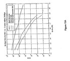
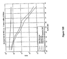
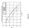
- Figures 13A through 13D are graphs comparing decoder performance in terms of bit error rate versus signal to noise ratio for hard decision, decoding with channel information, and with channel and location information.
- the solid line represents hard decisions using Hamming metrics.
- the dashed line represents to improvement grained through the use of channel information.
- the line with dashes and dots represents the improvement gained through the use of location information.
Landscapes
- Engineering & Computer Science (AREA)
- Physics & Mathematics (AREA)
- Probability & Statistics with Applications (AREA)
- Theoretical Computer Science (AREA)
- Computer Networks & Wireless Communication (AREA)
- Signal Processing (AREA)
- Artificial Intelligence (AREA)
- Power Engineering (AREA)
- Error Detection And Correction (AREA)
Abstract
Description

Claims (10)
- A method of signal decoding characterized by:accepting a received signal;quantizing the received signal to a point in a signal constellation plane to provide a quantized point;making a hard decision as to which constellation point the quantized point represents;determining scaling factors (k's) associated with each constellation point;using the scaling factors and hard decision point to determine decoder metrics; andproviding a decoder metrics and quantized point to a Viterbi decoder.
- The method of claim 1, wherein making a hard decision as to which constellation point the quantized point represents is further characterized by:determining which constellation point is closest to the quantized point; andassigning a value of the nearest constellation point to the quantized point.
- The method of claim 2, wherein determining which constellation point is closest to the quantized point is further characterized by:computing a Euclidean distance squared between the quantized point and the candidate constellation point; andselecting the constellation point with the smallest Euclidean distance squared as the closest constellation point.
- The method as in claim 3, wherein selecting the constellation point with a smallest Euclidean distance squared is further characterized by:(a) squaring an X direction distance between the quantized point and the candidate constellation point to provide a squared X direction distance;(b) squaring a Y direction distance between the quantized point and the candidate constellation point to provide a squared Y direction distance;(c) adding the squared X direction distance to the squared Y direction distance to find a Euclidean distance squared;(d) repeating steps a, b and c for all candidate points; and(e) selecting the candidate point with a smallest Euclidean distance squared.
- The method as in claim 1, wherein determining the scaling factors associated with each quantized point is further characterized by:determining an amount of noise necessary to create an error in a candidate bit; andassigning the scaling factor in proportion to the amount of noise necessary to create an error in a candidate bit.
- The method of claim 1, further characterized by:multiplying the scaling factors times a signal to noise ratio (SNR) scaling factor to provide a scaled SNR result; andusing the scaled SNR result to determine the decoder metrics.
- The method of claim 6, wherein using the scaled SNR result to determine the decoder metrics is further characterized by:using the results as an index into a branch metric table; andreading the metric associated with the index.
- A signal processing apparatus characterized by:an input for accepting a received signal;a quantizer that accepts the received signal from the input and quantizes the input to a point in a signal constellation plane to provide a quantized point;a hard decision unit that accepts the quantized point and determines a constellation point that the quantized point represents;a scaling factor unit that determines scaling factors associated with the constellation point; anda metric calculator that accepts the scaling factors and the constellation points and determines branch metrics for the constellation points.
- The signal processing apparatus of claim 8, further characterized by:a Viterbi decoder that accepts the constellation points and the branch metrics and produces decoded bits.
- The signal processing apparatus of claim 8, wherein the metric calculator is further characterized by:an input that accepts a signal to noise ratio (SNR);an input that accepts scaling factors; anda combination circuit that combines the scaling factors and SNR to create a branch metric.
Applications Claiming Priority (2)
| Application Number | Priority Date | Filing Date | Title |
|---|---|---|---|
| US27824 | 2001-12-20 | ||
| US10/027,824 US7027532B2 (en) | 2001-12-20 | 2001-12-20 | Viterbi decoding with channel and location information |
Publications (2)
| Publication Number | Publication Date |
|---|---|
| EP1326358A1 true EP1326358A1 (en) | 2003-07-09 |
| EP1326358B1 EP1326358B1 (en) | 2005-11-09 |
Family
ID=21839978
Family Applications (1)
| Application Number | Title | Priority Date | Filing Date |
|---|---|---|---|
| EP02090416A Expired - Lifetime EP1326358B1 (en) | 2001-12-20 | 2002-12-19 | Scaling of Viterbi decoding based on channel and location information |
Country Status (3)
| Country | Link |
|---|---|
| US (1) | US7027532B2 (en) |
| EP (1) | EP1326358B1 (en) |
| DE (1) | DE60207186T2 (en) |
Families Citing this family (7)
| Publication number | Priority date | Publication date | Assignee | Title |
|---|---|---|---|---|
| TWI271071B (en) * | 2003-11-06 | 2007-01-11 | Ind Tech Res Inst | Communication method of scalable QAM and scalable QAM system |
| US8204923B1 (en) * | 2006-10-31 | 2012-06-19 | Marvell International Ltd. | Systems and methods for scaling parameters |
| US8040985B2 (en) * | 2007-10-09 | 2011-10-18 | Provigent Ltd | Decoding of forward error correction codes in the presence of phase noise |
| US8261165B2 (en) * | 2008-11-14 | 2012-09-04 | Silicon Laboratories Inc. | Multi-syndrome error correction circuit |
| EP2398179B1 (en) * | 2010-06-11 | 2017-03-22 | Intel Deutschland GmbH | Method for detecting the validity of downlink control information in telecommunication user equipment, decoder and baseband receiver for performing same |
| CN103532905B (en) * | 2012-07-05 | 2017-09-19 | 北京新岸线移动通信技术有限公司 | Signal-noise ratio estimation method and device based on hard decision |
| EP3275145B1 (en) * | 2016-01-19 | 2019-09-11 | Huawei Technologies Co., Ltd. | Error-compensated direct digital modulation device |
Citations (3)
| Publication number | Priority date | Publication date | Assignee | Title |
|---|---|---|---|---|
| EP0465428A2 (en) * | 1990-07-05 | 1992-01-08 | Matsushita Electric Industrial Co., Ltd. | Digital modulated signal demodulator/decoder apparatus |
| WO2000033500A2 (en) * | 1998-12-03 | 2000-06-08 | Nokia Mobile Phones Limited | Improved rate determination technique utilising modified cumulative metrics |
| WO2001078241A2 (en) * | 2000-04-06 | 2001-10-18 | Lucent Technologies Inc. | Upstream data transmission |
Family Cites Families (5)
| Publication number | Priority date | Publication date | Assignee | Title |
|---|---|---|---|---|
| US5508752A (en) * | 1994-04-12 | 1996-04-16 | Lg Electronics Inc. | Partial response trellis decoder for high definition television (HDTV) system |
| KR0129577B1 (en) * | 1994-04-30 | 1998-04-10 | 배순훈 | Improved Metric Calculation Method for Image Receiving System using 32-Orthogonal Amplitude Modulation |
| US6421394B1 (en) * | 1998-12-31 | 2002-07-16 | Oguz Tanrikulu | Computer method and apparatus for modem point slicing |
| US6792055B1 (en) * | 2000-07-21 | 2004-09-14 | Rockwell Collins | Data communications receiver with automatic control of gain or threshold for soft decision decoding |
| US6928120B1 (en) * | 2000-09-25 | 2005-08-09 | Cingular Wireless Ii, Llc | Methods and apparatus for use in reducing residual phase error in OFDM communication signals |
-
2001
- 2001-12-20 US US10/027,824 patent/US7027532B2/en not_active Expired - Fee Related
-
2002
- 2002-12-19 DE DE60207186T patent/DE60207186T2/en not_active Expired - Lifetime
- 2002-12-19 EP EP02090416A patent/EP1326358B1/en not_active Expired - Lifetime
Patent Citations (3)
| Publication number | Priority date | Publication date | Assignee | Title |
|---|---|---|---|---|
| EP0465428A2 (en) * | 1990-07-05 | 1992-01-08 | Matsushita Electric Industrial Co., Ltd. | Digital modulated signal demodulator/decoder apparatus |
| WO2000033500A2 (en) * | 1998-12-03 | 2000-06-08 | Nokia Mobile Phones Limited | Improved rate determination technique utilising modified cumulative metrics |
| WO2001078241A2 (en) * | 2000-04-06 | 2001-10-18 | Lucent Technologies Inc. | Upstream data transmission |
Also Published As
| Publication number | Publication date |
|---|---|
| DE60207186T2 (en) | 2006-07-20 |
| US7027532B2 (en) | 2006-04-11 |
| DE60207186D1 (en) | 2005-12-15 |
| US20030118133A1 (en) | 2003-06-26 |
| EP1326358B1 (en) | 2005-11-09 |
Similar Documents
| Publication | Publication Date | Title |
|---|---|---|
| US5757821A (en) | Method and apparatus for detecting communication signals having unequal error protection | |
| US6597743B1 (en) | Reduced search symbol estimation algorithm | |
| US7076000B2 (en) | Soft-decision metric generation for higher order modulation | |
| US7159168B2 (en) | Iterative decoding with likelihood weighting | |
| US6907084B2 (en) | Method and apparatus for processing modulation symbols for soft input decoders | |
| US20020041634A1 (en) | VSB Transmission system | |
| US5566191A (en) | Soft decision maximum likelihood decoding method with adaptive metric | |
| CN111585698B (en) | A kind of multi-dimensional coding modulation method and decoding and demodulation method | |
| US8213552B2 (en) | Demodulation method | |
| US7027532B2 (en) | Viterbi decoding with channel and location information | |
| US20030018941A1 (en) | Method and apparatus for demodulation | |
| US5425037A (en) | Data transmission apparatus | |
| US7457377B2 (en) | Device for estimating a sequence of N bits corresponding to a received sequence of M digital data and associated methods | |
| US7388522B2 (en) | Sequentially decoded low density parity coding (LDPC) forward error correction (FEC) in orthogonal frequency division modulation (OFDM) systems | |
| US7139335B2 (en) | Optimal decision metric approximation in bit-soft decisions | |
| KR100651202B1 (en) | Soft decision demodulation device and method | |
| KR100747595B1 (en) | Soft decision symbol detection apparatus and method thereof of communication system having a plurality of transmit and receive antennas | |
| US12235366B2 (en) | Decoder for a receiver | |
| JPH09284348A (en) | Decryption method | |
| CN118509295A (en) | 16APSK grid coding modulation method and demodulation method thereof | |
| Ross et al. | Pragmatic Trellis Coded Modulation: A simulation using 24-sector quantized 8-PSK | |
| CN112290958A (en) | A Turbo Code Decoding Method for Low Error Flat Layer | |
| JPH05244018A (en) | Viterbi decoder | |
| US20050141651A1 (en) | Method and system for modifying branch metric of Viterbi decoder for uncorrelated signals | |
| JPH06177778A (en) | Viterbi decoder for subset determination |
Legal Events
| Date | Code | Title | Description |
|---|---|---|---|
| PUAI | Public reference made under article 153(3) epc to a published international application that has entered the european phase |
Free format text: ORIGINAL CODE: 0009012 |
|
| AK | Designated contracting states |
Designated state(s): AT BE BG CH CY CZ DE DK EE ES FI FR GB GR IE IT LI LU MC NL PT SE SI SK TR |
|
| AX | Request for extension of the european patent |
Extension state: AL LT LV MK RO |
|
| RIN1 | Information on inventor provided before grant (corrected) |
Inventor name: LAUER,JOSEPH PAUL.C/O BROADCOM CORPORATION |
|
| RAP1 | Party data changed (applicant data changed or rights of an application transferred) |
Owner name: BROADCOM CORPORATION |
|
| 17P | Request for examination filed |
Effective date: 20040109 |
|
| AKX | Designation fees paid |
Designated state(s): DE FR GB |
|
| 17Q | First examination report despatched |
Effective date: 20040326 |
|
| GRAP | Despatch of communication of intention to grant a patent |
Free format text: ORIGINAL CODE: EPIDOSNIGR1 |
|
| GRAS | Grant fee paid |
Free format text: ORIGINAL CODE: EPIDOSNIGR3 |
|
| GRAA | (expected) grant |
Free format text: ORIGINAL CODE: 0009210 |
|
| AK | Designated contracting states |
Kind code of ref document: B1 Designated state(s): DE FR GB |
|
| REG | Reference to a national code |
Ref country code: GB Ref legal event code: FG4D |
|
| REF | Corresponds to: |
Ref document number: 60207186 Country of ref document: DE Date of ref document: 20051215 Kind code of ref document: P |
|
| ET | Fr: translation filed | ||
| PLBE | No opposition filed within time limit |
Free format text: ORIGINAL CODE: 0009261 |
|
| STAA | Information on the status of an ep patent application or granted ep patent |
Free format text: STATUS: NO OPPOSITION FILED WITHIN TIME LIMIT |
|
| 26N | No opposition filed |
Effective date: 20060810 |
|
| REG | Reference to a national code |
Ref country code: FR Ref legal event code: CA |
|
| REG | Reference to a national code |
Ref country code: FR Ref legal event code: PLFP Year of fee payment: 14 |
|
| PGFP | Annual fee paid to national office [announced via postgrant information from national office to epo] |
Ref country code: DE Payment date: 20151231 Year of fee payment: 14 |
|
| REG | Reference to a national code |
Ref country code: FR Ref legal event code: PLFP Year of fee payment: 15 |
|
| PGFP | Annual fee paid to national office [announced via postgrant information from national office to epo] |
Ref country code: GB Payment date: 20161228 Year of fee payment: 15 |
|
| PGFP | Annual fee paid to national office [announced via postgrant information from national office to epo] |
Ref country code: FR Payment date: 20161227 Year of fee payment: 15 |
|
| REG | Reference to a national code |
Ref country code: DE Ref legal event code: R119 Ref document number: 60207186 Country of ref document: DE |
|
| REG | Reference to a national code |
Ref country code: GB Ref legal event code: 732E Free format text: REGISTERED BETWEEN 20171005 AND 20171011 |
|
| PG25 | Lapsed in a contracting state [announced via postgrant information from national office to epo] |
Ref country code: DE Free format text: LAPSE BECAUSE OF NON-PAYMENT OF DUE FEES Effective date: 20170701 |
|
| REG | Reference to a national code |
Ref country code: FR Ref legal event code: TP Owner name: AVAGO TECHNOLOGIES GENERAL IP PTE. LTD., SG Effective date: 20180228 |
|
| GBPC | Gb: european patent ceased through non-payment of renewal fee |
Effective date: 20171219 |
|
| REG | Reference to a national code |
Ref country code: FR Ref legal event code: ST Effective date: 20180831 |
|
| PG25 | Lapsed in a contracting state [announced via postgrant information from national office to epo] |
Ref country code: FR Free format text: LAPSE BECAUSE OF NON-PAYMENT OF DUE FEES Effective date: 20180102 |
|
| PG25 | Lapsed in a contracting state [announced via postgrant information from national office to epo] |
Ref country code: GB Free format text: LAPSE BECAUSE OF NON-PAYMENT OF DUE FEES Effective date: 20171219 |