EP1326298A1 - Solid polymer type fuel battery - Google Patents
Solid polymer type fuel battery Download PDFInfo
- Publication number
- EP1326298A1 EP1326298A1 EP01965697A EP01965697A EP1326298A1 EP 1326298 A1 EP1326298 A1 EP 1326298A1 EP 01965697 A EP01965697 A EP 01965697A EP 01965697 A EP01965697 A EP 01965697A EP 1326298 A1 EP1326298 A1 EP 1326298A1
- Authority
- EP
- European Patent Office
- Prior art keywords
- cell
- gas
- polymer electrolyte
- fuel cell
- electrolyte fuel
- Prior art date
- Legal status (The legal status is an assumption and is not a legal conclusion. Google has not performed a legal analysis and makes no representation as to the accuracy of the status listed.)
- Withdrawn
Links
Images





Classifications
-
- H—ELECTRICITY
- H01—ELECTRIC ELEMENTS
- H01M—PROCESSES OR MEANS, e.g. BATTERIES, FOR THE DIRECT CONVERSION OF CHEMICAL ENERGY INTO ELECTRICAL ENERGY
- H01M8/00—Fuel cells; Manufacture thereof
- H01M8/02—Details
-
- H—ELECTRICITY
- H01—ELECTRIC ELEMENTS
- H01M—PROCESSES OR MEANS, e.g. BATTERIES, FOR THE DIRECT CONVERSION OF CHEMICAL ENERGY INTO ELECTRICAL ENERGY
- H01M8/00—Fuel cells; Manufacture thereof
- H01M8/02—Details
- H01M8/0202—Collectors; Separators, e.g. bipolar separators; Interconnectors
- H01M8/023—Porous and characterised by the material
- H01M8/0241—Composites
- H01M8/0245—Composites in the form of layered or coated products
-
- H—ELECTRICITY
- H01—ELECTRIC ELEMENTS
- H01M—PROCESSES OR MEANS, e.g. BATTERIES, FOR THE DIRECT CONVERSION OF CHEMICAL ENERGY INTO ELECTRICAL ENERGY
- H01M4/00—Electrodes
- H01M4/86—Inert electrodes with catalytic activity, e.g. for fuel cells
-
- H—ELECTRICITY
- H01—ELECTRIC ELEMENTS
- H01M—PROCESSES OR MEANS, e.g. BATTERIES, FOR THE DIRECT CONVERSION OF CHEMICAL ENERGY INTO ELECTRICAL ENERGY
- H01M4/00—Electrodes
- H01M4/86—Inert electrodes with catalytic activity, e.g. for fuel cells
- H01M4/8605—Porous electrodes
-
- H—ELECTRICITY
- H01—ELECTRIC ELEMENTS
- H01M—PROCESSES OR MEANS, e.g. BATTERIES, FOR THE DIRECT CONVERSION OF CHEMICAL ENERGY INTO ELECTRICAL ENERGY
- H01M8/00—Fuel cells; Manufacture thereof
- H01M8/02—Details
- H01M8/0202—Collectors; Separators, e.g. bipolar separators; Interconnectors
- H01M8/023—Porous and characterised by the material
- H01M8/0241—Composites
-
- H—ELECTRICITY
- H01—ELECTRIC ELEMENTS
- H01M—PROCESSES OR MEANS, e.g. BATTERIES, FOR THE DIRECT CONVERSION OF CHEMICAL ENERGY INTO ELECTRICAL ENERGY
- H01M8/00—Fuel cells; Manufacture thereof
- H01M8/02—Details
- H01M8/0202—Collectors; Separators, e.g. bipolar separators; Interconnectors
- H01M8/023—Porous and characterised by the material
- H01M8/0234—Carbonaceous material
-
- H—ELECTRICITY
- H01—ELECTRIC ELEMENTS
- H01M—PROCESSES OR MEANS, e.g. BATTERIES, FOR THE DIRECT CONVERSION OF CHEMICAL ENERGY INTO ELECTRICAL ENERGY
- H01M8/00—Fuel cells; Manufacture thereof
- H01M8/02—Details
- H01M8/0202—Collectors; Separators, e.g. bipolar separators; Interconnectors
- H01M8/023—Porous and characterised by the material
- H01M8/0239—Organic resins; Organic polymers
-
- H—ELECTRICITY
- H01—ELECTRIC ELEMENTS
- H01M—PROCESSES OR MEANS, e.g. BATTERIES, FOR THE DIRECT CONVERSION OF CHEMICAL ENERGY INTO ELECTRICAL ENERGY
- H01M8/00—Fuel cells; Manufacture thereof
- H01M8/10—Fuel cells with solid electrolytes
- H01M8/1007—Fuel cells with solid electrolytes with both reactants being gaseous or vaporised
-
- Y—GENERAL TAGGING OF NEW TECHNOLOGICAL DEVELOPMENTS; GENERAL TAGGING OF CROSS-SECTIONAL TECHNOLOGIES SPANNING OVER SEVERAL SECTIONS OF THE IPC; TECHNICAL SUBJECTS COVERED BY FORMER USPC CROSS-REFERENCE ART COLLECTIONS [XRACs] AND DIGESTS
- Y02—TECHNOLOGIES OR APPLICATIONS FOR MITIGATION OR ADAPTATION AGAINST CLIMATE CHANGE
- Y02E—REDUCTION OF GREENHOUSE GAS [GHG] EMISSIONS, RELATED TO ENERGY GENERATION, TRANSMISSION OR DISTRIBUTION
- Y02E60/00—Enabling technologies; Technologies with a potential or indirect contribution to GHG emissions mitigation
- Y02E60/30—Hydrogen technology
- Y02E60/50—Fuel cells
Definitions
- This invention relates to improvements in polymer electrolyte fuel cells (PEFCs).
- a polymer electrolyte fuel cell is made up of a cell, two separators disposed on both sides of this cell so as to interpose the cell therebetween, and diffusion layers disposed between the aforesaid cell and the separators.
- the aforesaid cell consists of a solid polymer film and two reaction layers disposed on both sides of the film.
- Each of the aforesaid diffusion layers consists of carbon paper and a slurry layer formed on one major surface thereof.
- a groove for the passage of hydrogen gas is formed in the surface of one separator facing the cell, and a groove for the passage of air is formed in the other separator.
- the present invention has been made in view of these circumstances, and an object thereof is to provide a polymer electrolyte fuel cell in which at least a part of each diffusion layer is provided with a gas barrier for preventing the permeation of gas in a direction parallel to the major surface of the diffusion layer, so that the retention of water in the cell can be avoided, uniform electricity generation can be achieved over the whole surface of the cell, and water can be removed efficiently.
- a polymer electrolyte fuel cell comprising a cell having a solid polymer film, separators disposed on both sides of the cell so as to interpose the cell therebetween, and diffusion layers disposed between the cell and the separators and each having a substrate comprising an electrically conductive porous material and a slurry layer disposed on the substrate, wherein at least a part of each diffusion layer is provided with a gas barrier for preventing the permeation of gas in a direction parallel to the major surface of the diffusion layer.
- the gas barrier comprises a gas-impervious material layer formed by removing the material of the substrate from the part thereof intended for the formation of a gas barrier and filling the resulting vacant space with rubber or resin.
- the gas barrier comprises a projecting part of each separator which is formed in the part thereof intended for the formation of a gas barrier so as to have a greater thickness than its surroundings, and a compressed layer formed by compressing the part of the electrically conductive porous material corresponding to the projecting part as compared with its surroundings.
- the gas barrier comprises a resin-impregnated layer formed by infiltrating resin into the part of each separator which is intended for the formation of a gas barrier and thereby imparting gas tightness thereto.
- the substrate comprising an electrically conductive porous material is formed by subjecting carbon paper, carbon cloth or nonwoven carbon fabric to a water-repellent treatment with a fluororesin.
- the surface energy of the diffusion layers is in the range of 1 x 10 -3 to 5 x 10 -2 N/m.
- the flow rate, L A [l/min], of the fuel gas fed and the pressure loss, ⁇ P A [kgf/cm 2 ], satisfy the condition defined by ⁇ P A ⁇ 0.2 x L A
- the flow rate, L C [l/min], of the oxidant gas fed and the pressure loss, ⁇ P C [kgf/cm 2 ] satisfy the condition defined by ⁇ P C ⁇ 0.1 x L C .
- the gas permeability rate of the diffusion layers is not less than 1.5 x 10 -4 cm/s/Pa.
- the average porosity of the diffusion layers is not less than 45%.
- PEFC polymer electrolyte fuel cell
- FIG. 1 is an exploded cross-sectional view illustrating one embodiment of a polymer electrolyte fuel cell in accordance with the present invention.
- This fuel cell 1 is made up of a cell 2, separators 3a, 3b disposed on both sides of this cell 2 so as to interpose cell 2 therebetween, and diffusion layers 4 disposed between the aforesaid cell 2 and separators 3a, 3b.
- the aforesaid cell 2 consists of a solid polymer film 5 and reaction layers 6, 6b disposed on both sides of film 5.
- Solid polymer film 5 is a film formed, for example, of a perfluorosulfonic acid.
- Each of the aforesaid diffusion layers 4 consists of carbon paper 7 which is also called a substrate, and a slurry layer 8 formed on one major surface thereof.
- This carbon paper may be replaced by another electrically conductive porous material such as carbon cloth or nonwoven carbon fabric.
- Slurry layer 8 may be formed, for example, by mixing hydrophilic carbon black, hydrophobic carbon black and polytetrafluoroethylene in solvent naphtha to prepare a slurry, screen-printing the slurry on a surface of the diffusion layer, and firing it.
- a groove 9 for the passage of hydrogen gas is formed in the surface of one separator 3a facing the cell.
- a groove 10 for the passage of air is formed in the other separator 3b.
- one reaction layer 6a consists of a fuel electrode 11 and, for example, a platinum catalyst layer 12 formed on the side thereof adjacent to solid polymer film 5
- the other reaction layer 6b consists of an air electrode 13 and a platinum catalyst layer 12 formed on the side thereof adjacent to solid polymer film 5.
- Fuel electrode 11 is formed of a platinum alloy catalyst supported on carbon black and a material such as an electrolyte polymer
- air electrolyte 13 is formed of a platinum alloy catalyst supported on carbon black and a material such as an electrolyte polymer.
- the aforesaid separator 3a (or 3b) has a planar configuration in which a serpentine groove is formed as illustrated in FIG. 3. That is, in the separator of this type is configured in such a way that, when hydrogen gas, for example, is conveyed from an entrance hole 14 at a corner of separator 3a to a diagonally opposite discharge hole 15, the direction of gas flow is changed, for example, about three times in order to increase the flow velocity of the gas and thereby blow off any water present in the groove.
- the fuel gas and the oxidant gas may not flow in conformity with the shape of the groove but bypass it by flowing through the diffusion layer, as shown by the broken line in FIG. 3. This phenomenon should be avoided because water is retained in the cell to cause a corresponding reduction in reaction area and a deterioration in electricity generation performance.
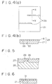
- FIG. 4(A) is a schematic plan view of a diffusion layer constituting a PEFC (polymer electrolyte fuel cell) in accordance with the first embodiment of the present invention
- FIG. 4(B) is a cross-sectional view taken along line X-X in FIG. 4(A). It is to be understood that the slurry layer is omitted in FIG. 4(A).
- slits 22 are made along the serpentine groove (not shown) of separator 3a (or 3b). These slits 22 of carbon paper 21 are filled with a gas barrier 23 formed, for example, of rubber.
- a slurry layer 8 is formed on carbon paper 21 containing the aforesaid gas barrier 23 to complete diffusion layer 24 together with carbon paper 21.
- gas barrier 23 is formed of a room temperature curing silicone rubber sealing material.
- the gas barrier is formed by pouring liquid silicone rubber into the slits made in the carbon paper, adjusting it to a predetermined thickness, and curing it at room temperature.
- carbon paper (substrate) 21 is provided with slits 22 along the serpentine groove (not shown) of separator 3a (or 3b), and these slits are filled with gas barrier 23 formed, for example, of rubber. Consequently, when the separators are attached to the cell and the gases are made to flow meanderingly, the gases can flow along the grooves of the separators without bypassing them. Accordingly, the retention of water in the cell can be prevented and uniform electricity generation can be achieved over the whole surface of the cell. Moreover, a uniform gas flow velocity can be obtained over the whole cell surface and water can be removed efficiently.
- FIG. 5 is a schematic cross-sectional view of a diffusion layer and a separator which constitute a PEFC in accordance with a second embodiment of the present invention.
- separator 25 has a projecting part 26 having a greater thickness than its surroundings.
- carbon paper 27 has a compressed layer (gas barrier) 28 formed so as to be recessed as compared with its surroundings.
- a slurry layer 8 is formed on the aforesaid carbon paper 27 having the aforesaid compressed layer 28.
- projecting part 26 having a greater thickness than its surroundings is formed at a predetermined position of separator 25, and compressed layer 28 corresponding to this projecting part 27 is formed in carbon paper 27. Consequently, similarly to the first embodiment, the retention of water in the cell can be prevented and uniform electricity generation can be achieved over the whole surface of the cell. Moreover, a uniform gas flow velocity can be obtained over the whole cell surface and water can be removed efficiently.
- FIG. 6 is a schematic cross-sectional view of a diffusion layer constituting a PEFC in accordance with a third embodiment of the present invention.
- a gas barrier comprises a resin-impregnated layer 31 formed by infiltrating a resin into the part of carbon paper (substrate) 21 which is intended for the formation of a gas barrier.
- This resin-impregnated layer 31 has gas tightness and does not allow gas to pass therethrough.
- a slurry layer 8 is formed on carbon paper 27 having the aforesaid resin-impregnated layer 31.
- resin-impregnated layer 31 having gas tightness is formed in the part of carbon paper 21 which is intended for the formation of a gas barrier. Consequently, similarly to the first embodiment, the retention of water in the cell can be prevented and uniform electricity generation can be achieved over the whole surface of the cell. Moreover, a uniform gas flow velocity can be obtained over the whole cell surface and water can be removed efficiently.
- Examples 1 and 2 fuel cells were fabricated by using a diffusion layer provided with a gas barrier comprising silicone polymer on the air electrode side.
- the number of grooves in the separator was 23 passes in Example 1 and 30 passes in Example 2.
- Comparative Examples 1 and 2 fuel cells were fabricated by using the same diffusion layer, except that the number of grooves in the separator was 10 passes in Comparative Example 1 and 1 pass in Comparative Example 2.
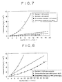
- FIG. 7 is a graph showing the relationship between the gas flow rate and the pressure loss on the air electrode side.
- a comparison between Comparative Examples 1 and 2 reveals that the pressure loss for a given flow rate increases dramatically by decreasing the number of grooves from 10 passes to 1 pass, and this permits the removal of water.
- Examples 1 and 2 show no substantial difference in pressure loss according to the number of grooves in the separator. It is believed that, in Examples 1 and 2, the gas barrier formed in the diffusion layer permitted the rectification of the gas.
- Example 3 a fuel cell was fabricated by using a diffusion layer provided with a gas barrier comprising silicone polymer on the fuel electrode side.
- the groove depth of the separator was 100% (0.3 mm deep) in Example 3.
- Comparative Examples 3 and 4 fuel cells were fabricated by using the same diffusion layer, except that the groove depth of the separator was 100% in Comparative Example 3 and 50% in Comparative Example 4.
- FIG. 8 is a graph showing the relationship between the gas flow rate and the pressure loss on the fuel electrode side.
- Example 3 When Example 3 is compared with Comparative Example 3 in FIG. 8, a pressure loss can be obtained without decreasing the groove depth of the separator. The reason for this seems to be that the gas barrier formed in the diffusion layer permitted the rectification of the gas.
- Example 3 When Example 3 is compared with Comparative Example 4, the pressure loss is lower in Example 3. However, it has been confirmed by the actual evaluation of electricity generation performance that the same voltage is produced under the same conditions as in Comparative Example 4 and, therefore, water is discharged effectively. It is believed that this is due to the gas-rectifying effect of the gas barrier. Thus, in Example 3, electricity generation performance equal to that of Comparative Example 4 can be achieved at lower pressures.
- FIG. 9 shows the relationship between the pressure loss (in one-to-one correspondence with the fuel flow rate) on the fuel electrode side and the voltage in each fuel cell.
- Fuel cells were fabricated as follows: In Example 4, the construction of Example 1 was employed on the air electrode side and the construction of Example 2 on the fuel electrode side. In Comparative Example 5, the construction of Comparative Example 1 was employed on the air electrode side and the construction of Comparative Example 1 on the fuel electrode side. In Comparative Example 6, the construction of Comparative Example 2 was employed on the air electrode side and the construction of Comparative Example 4 on the fuel electrode side.
- Comparative Example 5 exhibiting a high pressure loss on both the fuel electrode and the air electrode side (in which the groove depth is 50% as compared with Comparative Example 6), a stabilized high voltage can be obtained at relatively low pressure losses.
- a pressure loss can be obtained at low gas flow rates and that the small amount of gas causes a decrease of entrained water vapor and hence a decrease of water to be discharged.
- Comparative Example 6 exhibiting a low pressure loss on both the fuel electrode and the air electrode side, a stabilized high voltage cannot be obtained. It can be seen that, in order to obtain a stabilized high voltage, it is necessary to increase the pressure loss and hence feed large amounts of gases.
- Example 4 the highest voltage can be obtained at a much lower gas flow rate than in Comparative Examples 5 and 6.
- the reasons for this are believed to be that water can be efficiently discharged from the fuel cell owing to the gas-rectifying effect of the gas barrier formed in the diffusion layers and that an inert gas (N 2 ) contained in the fuel gas can be prevented from staying in the fuel cell and, therefore, the hydrogen concentration within the fuel cell can be maintained at an appropriate level.
- the flow rate (L A [l/min]) of the fuel gas fed thereto and the pressure loss ( ⁇ P A [kgf/cm 2 ]) in the polymer electrolyte fuel cell can satisfy the condition defined by ⁇ P A ⁇ 0.2 x L A .
- the flow rate (L C [l/min]) of the oxidant gas fed to the polymer electrolyte fuel cell and the pressure loss ( ⁇ P C [MPa]) in the polymer electrolyte fuel cell can satisfy the condition defined by ⁇ P C ⁇ 0.1 x L C . Even under these conditions, the retention of water in the cell can preferably be avoided, uniform electricity generation can be achieved over the whole surface of the cell, and water can be removed efficiently.
- a slurry layer comprising carbon black and polytetrafluoroethylene was formed on several types of carbon paper having different gas permeability rates. Then, slits were made therein so as to conform to the shape of the groove, and filled with silicone rubber. Electricity generation tests were carried out by using the gas diffusion layers so formed. The relationship between the gas permeability rate of the diffusion layers and the produced voltage is shown in FIG. 10. The produced voltage began to drop when the gas permeability rate was decreased to 1.5 x 10 -4 m/s/Pa or less. A voltage drop of about 10% was observed at 0.75 x 10 -4 m/s/Pa, and a voltage drop of 37% at 0.38 x 10 -4 m/s/Pa. These results indicate that the gas permeability rate of the diffusion layers should preferably be not less than 1.5 x 10 -4 m/s/Pa.
- a slurry layer comprising carbon black and polytetrafluoroethylene was formed on several types of carbon paper having different average porosities. Then, slits were made therein so as to conform to the shape of the groove, and filled with silicone rubber. Electricity generation tests were carried out by using the gas diffusion layers so formed. The relationship between the average porosity of the diffusion layers and the produced voltage was examined, and the results thus obtained are shown in FIG. 11. The produced voltage began to drop when the average porosity was decreased to 40% or less. A voltage drop of about 20% was observed at an average porosity of 35%, and a voltage drop of 35% at an average porosity of 20%. These results indicate that the average porosity of the diffusion layers should be not less than 40% and preferably not less than 45%.
- the separators used in these tests had a groove width of 1.0 mm, a rib width of 1.0 mm, and a groove depth of 0.3 mm. These dimensions should be determined on the basis of the balance between electrochemical performance and mechanical strength conditions for supporting the electrodes, and may be chosen in the ranges shown in Table 1 below, according to the intended purpose. As can be seen from Table 1, it is desirable that the groove width is in the range of 0.5 to 2.5 mm, the rib width is in the range of 0.5 to 2.5 mm, and the groove depth is in the range of 0.2 to 3.0 mm.
- Run 1 represents Test No. 1
- the size of the groove is such that the groove width is 0.5 mm, the rib width is 2.5 mm, and the length is 2.0 m.
- the present invention can provide polymer electrolyte fuel cells in which at least a part of each diffusion layer is provided with a gas barrier for preventing the permeation of gas in a direction parallel to the major surface thereof, so that the retention of water in the cell can be avoided, uniform electricity generation can be achieved over the whole surface of the cell, and water can be removed efficiently.
Landscapes
- Chemical & Material Sciences (AREA)
- Chemical Kinetics & Catalysis (AREA)
- Electrochemistry (AREA)
- General Chemical & Material Sciences (AREA)
- Life Sciences & Earth Sciences (AREA)
- Engineering & Computer Science (AREA)
- Manufacturing & Machinery (AREA)
- Sustainable Development (AREA)
- Sustainable Energy (AREA)
- Composite Materials (AREA)
- Fuel Cell (AREA)
- Inert Electrodes (AREA)
Abstract
A polymer electrolyte fuel cell comprising a cell having a
solid polymer film, separators disposed on both sides of the
cell so as to interpose the cell therebetween, and diffusion
layers disposed between the cell and the separators and each
having a substrate comprising an electrically conductive
porous material and a slurry layer disposed on the substrate,
wherein at least a part of each diffusion layer is provided
with a gas barrier for preventing the permeation of gas in a
direction parallel to the major surface of the diffusion layer.
Description
This invention relates to improvements in polymer
electrolyte fuel cells (PEFCs).
Conventionally, a polymer electrolyte fuel cell is made up
of a cell, two separators disposed on both sides of this cell
so as to interpose the cell therebetween, and diffusion layers
disposed between the aforesaid cell and the separators.
The aforesaid cell consists of a solid polymer film and
two reaction layers disposed on both sides of the film. Each
of the aforesaid diffusion layers consists of carbon paper and
a slurry layer formed on one major surface thereof. A groove
for the passage of hydrogen gas is formed in the surface of
one separator facing the cell, and a groove for the passage of
air is formed in the other separator.
However, conventional separators for use in polymer
electrolyte fuel cells have a problem in that the fuel gas and
the oxidant gas do not flow in conformity with the shape of
the groove but bypass it by flowing through the aforesaid
diffusion layers, so that water is retained in the cell to
cause a corresponding reduction in reaction area, a
deterioration in electricity generation performance, and a
risk of damage to the cell.
Meanwhile, in order to remove the water retained in the
cell, there has been employed a method in which the pressure
loss in the separators is sufficiently increased to introduce
the retained water into the gases as water vapor. However,
this method is advantageous in that the gas pressure losses in
the polymer electrolyte fuel cell are increased to cause an
increase in power consumption by auxiliary devices such as
compressors for feeding the gases, resulting in a reduction in
electricity generation efficiency of the whole fuel cell
system.
The present invention has been made in view of these
circumstances, and an object thereof is to provide a polymer
electrolyte fuel cell in which at least a part of each
diffusion layer is provided with a gas barrier for preventing
the permeation of gas in a direction parallel to the major
surface of the diffusion layer, so that the retention of water
in the cell can be avoided, uniform electricity generation can
be achieved over the whole surface of the cell, and water can
be removed efficiently.
According to the present invention, there is provided a
polymer electrolyte fuel cell comprising a cell having a solid
polymer film, separators disposed on both sides of the cell so
as to interpose the cell therebetween, and diffusion layers
disposed between the cell and the separators and each having a
substrate comprising an electrically conductive porous
material and a slurry layer disposed on the substrate, wherein
at least a part of each diffusion layer is provided with a gas
barrier for preventing the permeation of gas in a direction
parallel to the major surface of the diffusion layer.
In a preferred embodiment of the present invention, the
gas barrier comprises a gas-impervious material layer formed
by removing the material of the substrate from the part
thereof intended for the formation of a gas barrier and
filling the resulting vacant space with rubber or resin.
Moreover, in a preferred embodiment of the present
invention, the gas barrier comprises a projecting part of each
separator which is formed in the part thereof intended for the
formation of a gas barrier so as to have a greater thickness
than its surroundings, and a compressed layer formed by
compressing the part of the electrically conductive porous
material corresponding to the projecting part as compared with
its surroundings.
Moreover, in a preferred embodiment of the present
invention, the gas barrier comprises a resin-impregnated layer
formed by infiltrating resin into the part of each separator
which is intended for the formation of a gas barrier and
thereby imparting gas tightness thereto.
Moreover, in a preferred embodiment of the present
invention, the substrate comprising an electrically conductive
porous material is formed by subjecting carbon paper, carbon
cloth or nonwoven carbon fabric to a water-repellent treatment
with a fluororesin.
Moreover, in a preferred embodiment of the present
invention, the surface energy of the diffusion layers is in
the range of 1 x 10⁻³ to 5 x 10⁻² N/m.
Moreover, in a preferred embodiment of the present
invention, the flow rate, LA [l/min], of the fuel gas fed and
the pressure loss, ΔPA [kgf/cm2], satisfy the condition
defined by ΔPA ≤ 0.2 x LA, and the flow rate, LC [l/min], of
the oxidant gas fed and the pressure loss, ΔPC [kgf/cm2],
satisfy the condition defined by ΔPC ≤0.1 x LC.
Furthermore, in a preferred embodiment of the present
invention, the gas permeability rate of the diffusion layers
is not less than 1.5 x 10⁻⁴ cm/s/Pa.
Furthermore, in a preferred embodiment of the present
invention, the average porosity of the diffusion layers is not
less than 45%.
Several embodiments of the present invention will be
described hereinbelow with reference to the accompanying
drawings. However, these embodiments are not to be construed
to limit the technical scope of the present invention.
First of all, a polymer electrolyte fuel cell (PEFC) in
accordance with one embodiment of the present invention is
described with reference to the accompanying drawings.
FIG. 1 is an exploded cross-sectional view illustrating
one embodiment of a polymer electrolyte fuel cell in
accordance with the present invention. This fuel cell 1 is
made up of a cell 2, separators 3a, 3b disposed on both sides
of this cell 2 so as to interpose cell 2 therebetween, and
diffusion layers 4 disposed between the aforesaid cell 2 and
separators 3a, 3b.
The aforesaid cell 2 consists of a solid polymer film 5
and reaction layers 6, 6b disposed on both sides of film 5.
Each of the aforesaid diffusion layers 4 consists of
carbon paper 7 which is also called a substrate, and a slurry
layer 8 formed on one major surface thereof. This carbon paper
may be replaced by another electrically conductive porous
material such as carbon cloth or nonwoven carbon fabric.
Slurry layer 8 may be formed, for example, by mixing
hydrophilic carbon black, hydrophobic carbon black and
polytetrafluoroethylene in solvent naphtha to prepare a slurry,
screen-printing the slurry on a surface of the diffusion layer,
and firing it.
On the other hand, a groove 9 for the passage of hydrogen
gas is formed in the surface of one separator 3a facing the
cell. A groove 10 for the passage of air is formed in the
other separator 3b.
Now, the aforesaid cell 2 is more specifically explained.
As illustrated in FIG. 2, one reaction layer 6a consists of a
fuel electrode 11 and, for example, a platinum catalyst layer
12 formed on the side thereof adjacent to solid polymer film 5,
and the other reaction layer 6b consists of an air electrode
13 and a platinum catalyst layer 12 formed on the side thereof
adjacent to solid polymer film 5. Fuel electrode 11 is formed
of a platinum alloy catalyst supported on carbon black and a
material such as an electrolyte polymer, and air electrolyte
13 is formed of a platinum alloy catalyst supported on carbon
black and a material such as an electrolyte polymer.
In the aforesaid fuel electrode 11 and air electrode 13,
the following reactions take place.
Fuel electrode: H2 → 2H+ + 2e-
Air electrode: 2H+ + 2e- + (1/2)O2 → H2O
In the fuel cell of this construction, the aforesaid
separator 3a (or 3b) has a planar configuration in which a
serpentine groove is formed as illustrated in FIG. 3. That is,
in the separator of this type is configured in such a way that,
when hydrogen gas, for example, is conveyed from an entrance
hole 14 at a corner of separator 3a to a diagonally opposite
discharge hole 15, the direction of gas flow is changed, for
example, about three times in order to increase the flow
velocity of the gas and thereby blow off any water present in
the groove.
In this situation, the fuel gas and the oxidant gas may
not flow in conformity with the shape of the groove but bypass
it by flowing through the diffusion layer, as shown by the
broken line in FIG. 3. This phenomenon should be avoided
because water is retained in the cell to cause a corresponding
reduction in reaction area and a deterioration in electricity
generation performance.
Now, reference is made to FIGs. 4(A) and 4(B). As
previously described, FIG. 4(A) is a schematic plan view of a
diffusion layer constituting a PEFC (polymer electrolyte fuel
cell) in accordance with the first embodiment of the present
invention, and FIG. 4(B) is a cross-sectional view taken along
line X-X in FIG. 4(A). It is to be understood that the slurry
layer is omitted in FIG. 4(A).
In carbon paper 21 constituting the diffusion layer, slits
22 are made along the serpentine groove (not shown) of
separator 3a (or 3b). These slits 22 of carbon paper 21 are
filled with a gas barrier 23 formed, for example, of rubber.
A slurry layer 8 is formed on carbon paper 21 containing
the aforesaid gas barrier 23 to complete diffusion layer 24
together with carbon paper 21. In this case, gas barrier 23 is
formed of a room temperature curing silicone rubber sealing
material.
In this embodiment, the gas barrier is formed by pouring
liquid silicone rubber into the slits made in the carbon paper,
adjusting it to a predetermined thickness, and curing it at
room temperature.
Thus, according to the first embodiment, carbon paper
(substrate) 21 is provided with slits 22 along the serpentine
groove (not shown) of separator 3a (or 3b), and these slits
are filled with gas barrier 23 formed, for example, of rubber.
Consequently, when the separators are attached to the cell and
the gases are made to flow meanderingly, the gases can flow
along the grooves of the separators without bypassing them.
Accordingly, the retention of water in the cell can be
prevented and uniform electricity generation can be achieved
over the whole surface of the cell. Moreover, a uniform gas
flow velocity can be obtained over the whole cell surface and
water can be removed efficiently.
Now, reference is made to FIG. 5. FIG. 5 is a schematic
cross-sectional view of a diffusion layer and a separator
which constitute a PEFC in accordance with a second embodiment
of the present invention. In this embodiment, separator 25 has
a projecting part 26 having a greater thickness than its
surroundings. Correspondingly to projecting part 26, carbon
paper 27 has a compressed layer (gas barrier) 28 formed so as
to be recessed as compared with its surroundings. A slurry
layer 8 is formed on the aforesaid carbon paper 27 having the
aforesaid compressed layer 28.
Thus, according to the second embodiment, projecting part
26 having a greater thickness than its surroundings is formed
at a predetermined position of separator 25, and compressed
layer 28 corresponding to this projecting part 27 is formed in
carbon paper 27. Consequently, similarly to the first
embodiment, the retention of water in the cell can be
prevented and uniform electricity generation can be achieved
over the whole surface of the cell. Moreover, a uniform gas
flow velocity can be obtained over the whole cell surface and
water can be removed efficiently.
Now, reference is made to FIG. 6. FIG. 6 is a schematic
cross-sectional view of a diffusion layer constituting a PEFC
in accordance with a third embodiment of the present invention.
In this embodiment, a gas barrier comprises a resin-impregnated
layer 31 formed by infiltrating a resin into the
part of carbon paper (substrate) 21 which is intended for the
formation of a gas barrier. This resin-impregnated layer 31
has gas tightness and does not allow gas to pass therethrough.
A slurry layer 8 is formed on carbon paper 27 having the
aforesaid resin-impregnated layer 31.
Thus, according to the third embodiment, resin-impregnated
layer 31 having gas tightness is formed in the part of carbon
paper 21 which is intended for the formation of a gas barrier.
Consequently, similarly to the first embodiment, the retention
of water in the cell can be prevented and uniform electricity
generation can be achieved over the whole surface of the cell.
Moreover, a uniform gas flow velocity can be obtained over the
whole cell surface and water can be removed efficiently.
With regard to polymer electrolyte fuel cells in
accordance with the present invention, the present inventors
further examined their appropriate operating conditions and
the like on the basis of the following examples and
comparative examples.
In Examples 1 and 2, fuel cells were fabricated by using a
diffusion layer provided with a gas barrier comprising
silicone polymer on the air electrode side. The number of
grooves in the separator was 23 passes in Example 1 and 30
passes in Example 2.
In Comparative Examples 1 and 2, fuel cells were
fabricated by using the same diffusion layer, except that the
number of grooves in the separator was 10 passes in
Comparative Example 1 and 1 pass in Comparative Example 2.
FIG. 7 is a graph showing the relationship between the gas
flow rate and the pressure loss on the air electrode side. A
comparison between Comparative Examples 1 and 2 reveals that
the pressure loss for a given flow rate increases dramatically
by decreasing the number of grooves from 10 passes to 1 pass,
and this permits the removal of water.
However, a comparison between Examples 1 and 2 shows no
substantial difference in pressure loss according to the
number of grooves in the separator. It is believed that, in
Examples 1 and 2, the gas barrier formed in the diffusion
layer permitted the rectification of the gas.
When Examples 1 and 2 are compared with Comparative
Example 2, the pressure loss is lower in Examples 1 and 2.
However, it has been confirmed that, owing to the gas-rectifying
effect, water is effectively discharged to at least
the same extent as in Comparative Example 2. Accordingly, in
Examples 1 and 2, electricity generation performance equal to
that of Comparative Example 2 can be achieved at lower
pressures.
In Example 3, a fuel cell was fabricated by using a
diffusion layer provided with a gas barrier comprising
silicone polymer on the fuel electrode side. The groove depth
of the separator was 100% (0.3 mm deep) in Example 3.
In Comparative Examples 3 and 4, fuel cells were
fabricated by using the same diffusion layer, except that the
groove depth of the separator was 100% in Comparative Example
3 and 50% in Comparative Example 4.
FIG. 8 is a graph showing the relationship between the gas
flow rate and the pressure loss on the fuel electrode side.
A comparison between Comparative Examples 3 and 4 reveals
that the pressure loss for a given flow rate increases
dramatically by decreasing the groove depth from 100% to 50%,
and this permits the effective removal of water.
When Example 3 is compared with Comparative Example 3 in
FIG. 8, a pressure loss can be obtained without decreasing the
groove depth of the separator. The reason for this seems to be
that the gas barrier formed in the diffusion layer permitted
the rectification of the gas.
When Example 3 is compared with Comparative Example 4, the
pressure loss is lower in Example 3. However, it has been
confirmed by the actual evaluation of electricity generation
performance that the same voltage is produced under the same
conditions as in Comparative Example 4 and, therefore, water
is discharged effectively. It is believed that this is due to
the gas-rectifying effect of the gas barrier. Thus, in Example
3, electricity generation performance equal to that of
Comparative Example 4 can be achieved at lower pressures.
FIG. 9 shows the relationship between the pressure loss
(in one-to-one correspondence with the fuel flow rate) on the
fuel electrode side and the voltage in each fuel cell.
Fuel cells were fabricated as follows: In Example 4, the
construction of Example 1 was employed on the air electrode
side and the construction of Example 2 on the fuel electrode
side. In Comparative Example 5, the construction of
Comparative Example 1 was employed on the air electrode side
and the construction of Comparative Example 1 on the fuel
electrode side. In Comparative Example 6, the construction of
Comparative Example 2 was employed on the air electrode side
and the construction of Comparative Example 4 on the fuel
electrode side.
In Comparative Example 5 exhibiting a high pressure loss
on both the fuel electrode and the air electrode side (in
which the groove depth is 50% as compared with Comparative
Example 6), a stabilized high voltage can be obtained at
relatively low pressure losses. The reasons for this are
believed that a pressure loss can be obtained at low gas flow
rates and that the small amount of gas causes a decrease of
entrained water vapor and hence a decrease of water to be
discharged.
In Comparative Example 6 exhibiting a low pressure loss on
both the fuel electrode and the air electrode side, a
stabilized high voltage cannot be obtained. It can be seen
that, in order to obtain a stabilized high voltage, it is
necessary to increase the pressure loss and hence feed large
amounts of gases.
On the other hand, in Example 4, the highest voltage can
be obtained at a much lower gas flow rate than in Comparative
Examples 5 and 6. The reasons for this are believed to be that
water can be efficiently discharged from the fuel cell owing
to the gas-rectifying effect of the gas barrier formed in the
diffusion layers and that an inert gas (N2) contained in the
fuel gas can be prevented from staying in the fuel cell and,
therefore, the hydrogen concentration within the fuel cell can
be maintained at an appropriate level.
When a polymer electrolyte fuel cell is provided with a
gas barrier in accordance with the present invention, the flow
rate (LA [l/min]) of the fuel gas fed thereto and the pressure
loss (ΔPA [kgf/cm2]) in the polymer electrolyte fuel cell can
satisfy the condition defined by ΔPA ≤ 0.2 x LA. Similarly,
the flow rate (LC [l/min]) of the oxidant gas fed to the
polymer electrolyte fuel cell and the pressure loss (ΔPC
[MPa]) in the polymer electrolyte fuel cell can satisfy the
condition defined by ΔPC ≤ 0.1 x LC. Even under these
conditions, the retention of water in the cell can preferably
be avoided, uniform electricity generation can be achieved
over the whole surface of the cell, and water can be removed
efficiently.
The condition for the fuel gas flow rate, as defined by by
ΔPA ≤ 0.2 x LA, has been derived from the fact that, on the
basis of the results of Example 3 shown in FIG. 8, the limit
of the lowest pressure loss permitting operation lies under
the straight line of Example 3.
The condition for the oxidant gas flow rate, as defined by
ΔPC ≤ 0.1 x LC, has been derived from the fact that the limit
of the lowest pressure loss permitting operation lies under
the straight line of Example 1 in FIG. 7.
A slurry layer comprising carbon black and
polytetrafluoroethylene was formed on several types of carbon
paper having different gas permeability rates. Then, slits
were made therein so as to conform to the shape of the groove,
and filled with silicone rubber. Electricity generation tests
were carried out by using the gas diffusion layers so formed.
The relationship between the gas permeability rate of the
diffusion layers and the produced voltage is shown in FIG. 10.
The produced voltage began to drop when the gas permeability
rate was decreased to 1.5 x 10⁻⁴ m/s/Pa or less. A voltage
drop of about 10% was observed at 0.75 x 10⁻⁴ m/s/Pa, and a
voltage drop of 37% at 0.38 x 10⁻⁴ m/s/Pa. These results
indicate that the gas permeability rate of the diffusion
layers should preferably be not less than 1.5 x 10⁻⁴ m/s/Pa.
A slurry layer comprising carbon black and
polytetrafluoroethylene was formed on several types of carbon
paper having different average porosities. Then, slits were
made therein so as to conform to the shape of the groove, and
filled with silicone rubber. Electricity generation tests were
carried out by using the gas diffusion layers so formed. The
relationship between the average porosity of the diffusion
layers and the produced voltage was examined, and the results
thus obtained are shown in FIG. 11. The produced voltage began
to drop when the average porosity was decreased to 40% or less.
A voltage drop of about 20% was observed at an average
porosity of 35%, and a voltage drop of 35% at an average
porosity of 20%. These results indicate that the average
porosity of the diffusion layers should be not less than 40%
and preferably not less than 45%.
The separators used in these tests had a groove width of
1.0 mm, a rib width of 1.0 mm, and a groove depth of 0.3 mm.
These dimensions should be determined on the basis of the
balance between electrochemical performance and mechanical
strength conditions for supporting the electrodes, and may be
chosen in the ranges shown in Table 1 below, according to the
intended purpose. As can be seen from Table 1, it is desirable
that the groove width is in the range of 0.5 to 2.5 mm, the
rib width is in the range of 0.5 to 2.5 mm, and the groove
depth is in the range of 0.2 to 3.0 mm.
| Shape of Groove and Electricity Generation Performance | |||||||||
| Run | Electrode area [cm2] | Current density [A/cm2] | Groove width [m] | Rib width [m] | Depth [mm] | Length [m] | Longitudinal electrode length [m] | Pressure loss [mmAq] | Electricity generation performance |
| 1 | 1600 | 1 | 5.0E-04 | 2.5E-03 | 3 | 2.0E+00 | [m] 0.4 | 802 | Good |
| 2 | 1600 | 0.5 | 5.0E-04 | 2.5E-03 | 3 | 2.8E+00 | 0.4 | 786 | Good |
| 3 | 1600 | 1 | 2.5E-03 | 2.5E-03 | 1 | 1.2E+00 | 0.4 | 452 | Good |
| 4 | 1600 | 0.2 | 5.0E-04 | 2.5E-03 | 1 | 2.0E+00 | 0.4 | 692 | Good |
| 5 | 1600 | 1 | 2.5E-03 | 2.5E-03 | 0.2 | 4.0E-01 | 0.4 | 5018 | Good |
| 6 | 1600 | 0.2 | 5.0E-04 | 5.0E-04 | 0.2 | 4.0E-01 | 0.4 | 337 | Good |
| 7 | 300 | 1 | 5.0E-04 | 2.5E-03 | 3 | 1.6E+00 | 0.17 | 487 | Good |
| 8 | 300 | 1 | 2.5E-03 | 2.5E-03 | 1 | 8.7E-01 | 0.17 | 236 | Good |
| 9 | 300 | 0.2 | 5.0E-04 | 2.5E-03 | 1 | 1.6E+00 | 0.17 | 421 | Good |
| 10 | 300 | 1 | 5.0E-04 | 5.0E-04 | 0.2 | 1.7E-01 | 0.17 | 316 | Good |
| 11 | 300 | 0.2 | 5.0E-04 | 5.0E-04 | 0.2 | 1.7E-01 | 0.17 | 63 | Good |
| 12 | 150 | 1 | 2.5E-03 | 2.5E-03 | 1 | 8.6E-01 | 0.12 | 231 | Good |
| 13 | 150 | 0.5 | 5.0E-04 | 2.5E-03 | 1 | 6.1E-01 | 0.12 | 162 | Good |
| 14 | 150 | 1 | 2.5E-03 | 2.5E-03 | 0.2 | 1.2E-01 | 0.12 | 470 | Good |
| 15 | 150 | 0.2 | 5.0E-04 | 5.0E-04 | 0.2 | 1.2E-01 | 0.12 | 32 | Good |
| 16 | 25 | 1 | 5.0E-04 | 2.5E-03 | 1 | 3.5E-01 | 0.05 | 106 | Good |
| 17 | 25 | 1 | 2.5E-03 | 2.5E-03 | 0.2 | 5.0E-02 | 0.05 | 78 | Good |
| 18 | 25 | 0.2 | 5.0E-04 | 5.0E-04 | 0.2 | 1.5E-01 | 0.05 | 47 | Good |
In Table 1, "Run" represents a test number (for example,
Run 1 represents Test No. 1), and the size of the groove is
such that the groove width is 0.5 mm, the rib width is 2.5 mm,
and the length is 2.0 m.
It is to be understood that the present invention is not
limited to the above-described embodiments, and it is intended
to cover all such changes, modifications and equivalent
arrangements as fall within the scope of the appended claims.
Thus, the present invention can provide polymer
electrolyte fuel cells in which at least a part of each
diffusion layer is provided with a gas barrier for preventing
the permeation of gas in a direction parallel to the major
surface thereof, so that the retention of water in the cell
can be avoided, uniform electricity generation can be achieved
over the whole surface of the cell, and water can be removed
efficiently.
Claims (9)
- A polymer electrolyte fuel cell comprising a cell having a solid polymer film, separators disposed on both sides of said cell so as to interpose said cell therebetween, and diffusion layers disposed between said cell and the separators and each having a substrate comprising an electrically conductive porous material and a slurry layer disposed on the substrate, wherein at least a part of each diffusion layer is provided with a gas barrier for preventing the permeation of gas in a direction parallel to the major surface of the diffusion layer.
- A polymer electrolyte fuel cell as claimed in claim 1 wherein said gas barrier comprises a gas-impervious material layer formed by removing the material of the substrate from the part thereof intended for the formation of a gas barrier and filling the resulting vacant space with rubber or resin.
- A polymer electrolyte fuel cell as claimed in claim 1 wherein said gas barrier comprises a projecting part of each separator which is formed in the part thereof intended for the formation of a gas barrier so as to have a greater thickness than its surroundings, and a compressed layer formed by compressing the part of said electrically conductive porous material corresponding to the projecting part as compared with its surroundings.
- A polymer electrolyte fuel cell as claimed in claim 1 wherein said gas barrier comprises a resin-impregnated layer formed by infiltrating resin into the part of each separator which is intended for the formation of a gas barrier and thereby imparting gas tightness thereto.
- A polymer electrolyte fuel cell as claimed in any of claims 1 to 4 wherein said substrate comprising an electrically conductive porous material is formed by subjecting carbon paper, carbon cloth or nonwoven carbon fabric to a water-repellent treatment with a fluororesin.
- A polymer electrolyte fuel cell as claimed in any of claims 1 to 5 wherein the surface energy of said diffusion layers is in the range of 1 x 10⁻³ to 5 x 10⁻² N/m.
- A polymer electrolyte fuel cell as claimed in any of claims 1 to 6 wherein the flow rate, LA [l/min], of the fuel gas fed and the pressure loss, ΔPA [kgf/cm2], satisfy the condition defined by ΔPA ≤ 0.2 x LA, and the flow rate, LC [l/min], of the oxidant gas fed and the pressure loss, ΔPC [kgf/cm2], satisfy the condition defined by ΔPC ≤ 0.1 x LC.
- A polymer electrolyte fuel cell as claimed in any of claims 1 to 7 wherein the gas permeability rate of said diffusion layers is not less than 1.5 x 10⁻⁴ cm/s/Pa.
- A polymer electrolyte fuel cell as claimed in any of claims 1 to 8 wherein the average porosity of said diffusion layers is not less than 45%.
Applications Claiming Priority (3)
| Application Number | Priority Date | Filing Date | Title |
|---|---|---|---|
| JP2000282397 | 2000-09-18 | ||
| JP2000282397 | 2000-09-18 | ||
| PCT/JP2001/008103 WO2002023655A1 (en) | 2000-09-18 | 2001-09-18 | Solid polymer type fuel battery |
Publications (2)
| Publication Number | Publication Date |
|---|---|
| EP1326298A1 true EP1326298A1 (en) | 2003-07-09 |
| EP1326298A4 EP1326298A4 (en) | 2006-07-19 |
Family
ID=18766926
Family Applications (1)
| Application Number | Title | Priority Date | Filing Date |
|---|---|---|---|
| EP01965697A Withdrawn EP1326298A4 (en) | 2000-09-18 | 2001-09-18 | Solid polymer type fuel battery |
Country Status (10)
| Country | Link |
|---|---|
| US (1) | US7001688B2 (en) |
| EP (1) | EP1326298A4 (en) |
| JP (1) | JP3702273B2 (en) |
| KR (1) | KR100458783B1 (en) |
| CN (1) | CN1299379C (en) |
| AU (1) | AU784147B2 (en) |
| BR (1) | BR0107218A (en) |
| CA (1) | CA2391587C (en) |
| MX (1) | MXPA02004950A (en) |
| WO (1) | WO2002023655A1 (en) |
Cited By (2)
| Publication number | Priority date | Publication date | Assignee | Title |
|---|---|---|---|---|
| WO2006111847A3 (en) * | 2005-04-22 | 2007-03-01 | Nissan Motor | Fuel cells and fuel cell separators |
| CN114976393A (en) * | 2021-02-26 | 2022-08-30 | 本田技研工业株式会社 | Soft pack battery, manufacturing method of soft pack battery |
Families Citing this family (14)
| Publication number | Priority date | Publication date | Assignee | Title |
|---|---|---|---|---|
| DE10145875B4 (en) * | 2001-09-18 | 2010-09-16 | Daimler Ag | Membrane electrode unit for a self-humidifying fuel cell |
| GB2382455B (en) * | 2001-11-07 | 2004-10-13 | Intelligent Energy Ltd | Fuel cell fluid flow field plates |
| JP2004214019A (en) * | 2002-12-27 | 2004-07-29 | Nissan Motor Co Ltd | Fuel cell |
| JP2005243442A (en) * | 2004-02-26 | 2005-09-08 | Mitsubishi Electric Corp | Fuel cell |
| CN100379069C (en) * | 2004-12-21 | 2008-04-02 | 松下电器产业株式会社 | Direct Methanol Fuel Cell |
| JP4581702B2 (en) * | 2005-01-26 | 2010-11-17 | トヨタ自動車株式会社 | Fuel cell |
| DE102005022484B4 (en) * | 2005-05-11 | 2016-02-18 | Carl Freudenberg Kg | Gas diffusion layer and arrangement comprising two gas diffusion layers |
| US7722979B2 (en) * | 2005-10-14 | 2010-05-25 | Gm Global Technology Operations, Inc. | Fuel cells with hydrophobic diffusion medium |
| US7790324B2 (en) * | 2006-02-02 | 2010-09-07 | Panasonic Corporation | Separator plate and fuel cell |
| US8690960B2 (en) * | 2009-11-24 | 2014-04-08 | Covidien Lp | Reinforced tissue patch |
| AU2012382382A1 (en) | 2012-06-12 | 2015-01-15 | Aquahydrex Pty Ltd | Breathable electrode and method for use in water splitting |
| CN105594016A (en) * | 2013-07-31 | 2016-05-18 | 奥克海德莱克斯控股有限公司 | Composite three-dimensional electrode and manufacturing method |
| AU2014412084B2 (en) * | 2014-11-18 | 2020-01-23 | Parafoil Design & Engineering Pte Ltd | A flood barrier |
| KR20210122260A (en) | 2019-02-01 | 2021-10-08 | 아쿠아하이드렉스, 인크. | Electrochemical systems with limited electrolytes |
Family Cites Families (17)
| Publication number | Priority date | Publication date | Assignee | Title |
|---|---|---|---|---|
| US4279970A (en) * | 1980-02-20 | 1981-07-21 | Electric Power Research Institute, Inc. | Electrochemical cell including ribbed electrode substrates |
| US4365008A (en) * | 1981-07-27 | 1982-12-21 | United Technologies Corporation | Densified edge seals for fuel cell components |
| JPS6273570A (en) | 1985-09-27 | 1987-04-04 | Toshiba Corp | Manufacture of fuel cell |
| US4824739A (en) * | 1986-12-29 | 1989-04-25 | International Fuel Cells | Method of operating an electrochemical cell stack |
| JPH02226663A (en) | 1989-02-23 | 1990-09-10 | Toray Ind Inc | Gas seal method for base material end for fuel cell |
| US5252410A (en) * | 1991-09-13 | 1993-10-12 | Ballard Power Systems Inc. | Lightweight fuel cell membrane electrode assembly with integral reactant flow passages |
| US5264299A (en) * | 1991-12-26 | 1993-11-23 | International Fuel Cells Corporation | Proton exchange membrane fuel cell support plate and an assembly including the same |
| CA2139167C (en) * | 1993-12-29 | 1997-12-02 | Keijiro Yamashita | Electrode used in electrochemical reaction and fuel cell using the same |
| JPH0845517A (en) * | 1994-07-28 | 1996-02-16 | Tanaka Kikinzoku Kogyo Kk | Sealing structure for polymer electrolyte fuel cell and manufacturing method thereof |
| US6106965A (en) * | 1996-03-29 | 2000-08-22 | Mazda Motor Corporation | Polymer electrolyte fuel cell |
| JPH09265992A (en) * | 1996-03-29 | 1997-10-07 | Mazda Motor Corp | Fuel cell electrode structure |
| US6146780A (en) * | 1997-01-24 | 2000-11-14 | Lynntech, Inc. | Bipolar separator plates for electrochemical cell stacks |
| US5976726A (en) * | 1997-05-01 | 1999-11-02 | Ballard Power Systems Inc. | Electrochemical cell with fluid distribution layer having integral sealing capability |
| US6468682B1 (en) * | 2000-05-17 | 2002-10-22 | Avista Laboratories, Inc. | Ion exchange membrane fuel cell |
| KR100750021B1 (en) * | 2000-06-29 | 2007-08-16 | 엔오케이 가부시키가이샤 | Component parts for fuel cells |
| CA2356008C (en) * | 2000-09-01 | 2010-01-05 | Honda Giken Kogyo Kabushiki Kaisha | Membrane electrode assembly for fuel cell and method for producing the same |
| AU2001260606B2 (en) * | 2000-11-21 | 2006-10-19 | Nok Corporation | Constituent part for fuel cell |
-
2001
- 2001-09-18 WO PCT/JP2001/008103 patent/WO2002023655A1/en not_active Ceased
- 2001-09-18 BR BR0107218-8A patent/BR0107218A/en not_active Application Discontinuation
- 2001-09-18 CA CA002391587A patent/CA2391587C/en not_active Expired - Fee Related
- 2001-09-18 KR KR10-2002-7006377A patent/KR100458783B1/en not_active Expired - Fee Related
- 2001-09-18 CN CNB018028020A patent/CN1299379C/en not_active Expired - Fee Related
- 2001-09-18 US US10/129,133 patent/US7001688B2/en not_active Expired - Lifetime
- 2001-09-18 AU AU86272/01A patent/AU784147B2/en not_active Ceased
- 2001-09-18 MX MXPA02004950A patent/MXPA02004950A/en unknown
- 2001-09-18 JP JP2002527595A patent/JP3702273B2/en not_active Expired - Lifetime
- 2001-09-18 EP EP01965697A patent/EP1326298A4/en not_active Withdrawn
Cited By (3)
| Publication number | Priority date | Publication date | Assignee | Title |
|---|---|---|---|---|
| WO2006111847A3 (en) * | 2005-04-22 | 2007-03-01 | Nissan Motor | Fuel cells and fuel cell separators |
| US7556878B2 (en) | 2005-04-22 | 2009-07-07 | Nissan Motor Co. Ltd. | Fuel cell with separator and porous support member including high density portion |
| CN114976393A (en) * | 2021-02-26 | 2022-08-30 | 本田技研工业株式会社 | Soft pack battery, manufacturing method of soft pack battery |
Also Published As
| Publication number | Publication date |
|---|---|
| WO2002023655A1 (en) | 2002-03-21 |
| CN1393042A (en) | 2003-01-22 |
| BR0107218A (en) | 2002-08-27 |
| US7001688B2 (en) | 2006-02-21 |
| AU784147B2 (en) | 2006-02-09 |
| MXPA02004950A (en) | 2003-10-14 |
| JPWO2002023655A1 (en) | 2004-01-29 |
| EP1326298A4 (en) | 2006-07-19 |
| KR100458783B1 (en) | 2004-12-03 |
| KR20020064316A (en) | 2002-08-07 |
| CA2391587C (en) | 2008-08-05 |
| CN1299379C (en) | 2007-02-07 |
| US20030008200A1 (en) | 2003-01-09 |
| AU8627201A (en) | 2002-03-26 |
| CA2391587A1 (en) | 2002-03-21 |
| JP3702273B2 (en) | 2005-10-05 |
Similar Documents
| Publication | Publication Date | Title |
|---|---|---|
| US7001688B2 (en) | Solid polymer type fuel battery | |
| US6756149B2 (en) | Electrochemical fuel cell with non-uniform fluid flow design | |
| US4729932A (en) | Fuel cell with integrated cooling water/static water removal means | |
| US6780533B2 (en) | Fuel cell having interdigitated flow channels and water transport plates | |
| CN103053057B (en) | Fuel cell | |
| US8003278B2 (en) | Fuel cell | |
| KR101388755B1 (en) | Fuel cell unit and fuel cell stack | |
| JP4549617B2 (en) | Fuel cell | |
| US7745063B2 (en) | Fuel cell stack | |
| CN100585927C (en) | The fuel cell | |
| US20020012827A1 (en) | Fuel cell, separator for the same and method for distributing gas in fuel cell | |
| EP1187240A1 (en) | Operation method for polymer electrolytic fuel cell | |
| US20040115486A1 (en) | Fuel cell | |
| EP1533859A2 (en) | Diffusion layer for a fuel cell | |
| JPH0529006A (en) | Fuel cell | |
| US20090087711A1 (en) | Fuel cell electrode, fuel cell, and fuel cell stack | |
| JP2012099382A (en) | Separator for fuel cell, fuel cell | |
| JP4186762B2 (en) | Polymer electrolyte fuel cell | |
| US20130260277A1 (en) | Diffusion layer structure of fuel cell | |
| JP2002270197A (en) | Polymer electrolyte fuel cell | |
| JP2005235525A (en) | Membrane / electrode assembly and polymer electrolyte fuel cell using the same | |
| KR102610727B1 (en) | Separator for fuel cell and fuel cell comprising thereof | |
| JPH08287924A (en) | Polymer electrolyte fuel cell | |
| JP2022092379A (en) | Gas diffusion layer | |
| CN113948731A (en) | Multi-perforated plates for fuel cell separators and fuel cells |
Legal Events
| Date | Code | Title | Description |
|---|---|---|---|
| PUAI | Public reference made under article 153(3) epc to a published international application that has entered the european phase |
Free format text: ORIGINAL CODE: 0009012 |
|
| 17P | Request for examination filed |
Effective date: 20020516 |
|
| AK | Designated contracting states |
Designated state(s): CH DE FR GB IT LI |
|
| A4 | Supplementary search report drawn up and despatched |
Effective date: 20060620 |
|
| 17Q | First examination report despatched |
Effective date: 20061006 |
|
| GRAP | Despatch of communication of intention to grant a patent |
Free format text: ORIGINAL CODE: EPIDOSNIGR1 |
|
| STAA | Information on the status of an ep patent application or granted ep patent |
Free format text: STATUS: THE APPLICATION IS DEEMED TO BE WITHDRAWN |
|
| 18D | Application deemed to be withdrawn |
Effective date: 20091103 |