EP1326243A1 - Optical recording medium - Google Patents
Optical recording medium Download PDFInfo
- Publication number
- EP1326243A1 EP1326243A1 EP01963578A EP01963578A EP1326243A1 EP 1326243 A1 EP1326243 A1 EP 1326243A1 EP 01963578 A EP01963578 A EP 01963578A EP 01963578 A EP01963578 A EP 01963578A EP 1326243 A1 EP1326243 A1 EP 1326243A1
- Authority
- EP
- European Patent Office
- Prior art keywords
- land
- height
- optical recording
- recording medium
- prepits
- Prior art date
- Legal status (The legal status is an assumption and is not a legal conclusion. Google has not performed a legal analysis and makes no representation as to the accuracy of the status listed.)
- Withdrawn
Links
Images

Classifications
-
- G—PHYSICS
- G11—INFORMATION STORAGE
- G11B—INFORMATION STORAGE BASED ON RELATIVE MOVEMENT BETWEEN RECORD CARRIER AND TRANSDUCER
- G11B7/00—Recording or reproducing by optical means, e.g. recording using a thermal beam of optical radiation by modifying optical properties or the physical structure, reproducing using an optical beam at lower power by sensing optical properties; Record carriers therefor
- G11B7/24—Record carriers characterised by shape, structure or physical properties, or by the selection of the material
- G11B7/241—Record carriers characterised by shape, structure or physical properties, or by the selection of the material characterised by the selection of the material
- G11B7/242—Record carriers characterised by shape, structure or physical properties, or by the selection of the material characterised by the selection of the material of recording layers
- G11B7/244—Record carriers characterised by shape, structure or physical properties, or by the selection of the material characterised by the selection of the material of recording layers comprising organic materials only
- G11B7/249—Record carriers characterised by shape, structure or physical properties, or by the selection of the material characterised by the selection of the material of recording layers comprising organic materials only containing organometallic compounds
- G11B7/2495—Record carriers characterised by shape, structure or physical properties, or by the selection of the material characterised by the selection of the material of recording layers comprising organic materials only containing organometallic compounds as anions
-
- G—PHYSICS
- G11—INFORMATION STORAGE
- G11B—INFORMATION STORAGE BASED ON RELATIVE MOVEMENT BETWEEN RECORD CARRIER AND TRANSDUCER
- G11B7/00—Recording or reproducing by optical means, e.g. recording using a thermal beam of optical radiation by modifying optical properties or the physical structure, reproducing using an optical beam at lower power by sensing optical properties; Record carriers therefor
- G11B7/007—Arrangement of the information on the record carrier, e.g. form of tracks, actual track shape, e.g. wobbled, or cross-section, e.g. v-shaped; Sequential information structures, e.g. sectoring or header formats within a track
- G11B7/00745—Sectoring or header formats within a track
-
- G—PHYSICS
- G11—INFORMATION STORAGE
- G11B—INFORMATION STORAGE BASED ON RELATIVE MOVEMENT BETWEEN RECORD CARRIER AND TRANSDUCER
- G11B7/00—Recording or reproducing by optical means, e.g. recording using a thermal beam of optical radiation by modifying optical properties or the physical structure, reproducing using an optical beam at lower power by sensing optical properties; Record carriers therefor
- G11B7/24—Record carriers characterised by shape, structure or physical properties, or by the selection of the material
- G11B7/2407—Tracks or pits; Shape, structure or physical properties thereof
- G11B7/24073—Tracks
- G11B7/24079—Width or depth
-
- G—PHYSICS
- G11—INFORMATION STORAGE
- G11B—INFORMATION STORAGE BASED ON RELATIVE MOVEMENT BETWEEN RECORD CARRIER AND TRANSDUCER
- G11B7/00—Recording or reproducing by optical means, e.g. recording using a thermal beam of optical radiation by modifying optical properties or the physical structure, reproducing using an optical beam at lower power by sensing optical properties; Record carriers therefor
- G11B7/24—Record carriers characterised by shape, structure or physical properties, or by the selection of the material
- G11B7/2407—Tracks or pits; Shape, structure or physical properties thereof
- G11B7/24085—Pits
-
- G—PHYSICS
- G11—INFORMATION STORAGE
- G11B—INFORMATION STORAGE BASED ON RELATIVE MOVEMENT BETWEEN RECORD CARRIER AND TRANSDUCER
- G11B7/00—Recording or reproducing by optical means, e.g. recording using a thermal beam of optical radiation by modifying optical properties or the physical structure, reproducing using an optical beam at lower power by sensing optical properties; Record carriers therefor
- G11B7/24—Record carriers characterised by shape, structure or physical properties, or by the selection of the material
- G11B7/241—Record carriers characterised by shape, structure or physical properties, or by the selection of the material characterised by the selection of the material
- G11B7/242—Record carriers characterised by shape, structure or physical properties, or by the selection of the material characterised by the selection of the material of recording layers
- G11B7/244—Record carriers characterised by shape, structure or physical properties, or by the selection of the material characterised by the selection of the material of recording layers comprising organic materials only
- G11B7/246—Record carriers characterised by shape, structure or physical properties, or by the selection of the material characterised by the selection of the material of recording layers comprising organic materials only containing dyes
- G11B7/2467—Record carriers characterised by shape, structure or physical properties, or by the selection of the material characterised by the selection of the material of recording layers comprising organic materials only containing dyes azo-dyes
-
- G—PHYSICS
- G11—INFORMATION STORAGE
- G11B—INFORMATION STORAGE BASED ON RELATIVE MOVEMENT BETWEEN RECORD CARRIER AND TRANSDUCER
- G11B7/00—Recording or reproducing by optical means, e.g. recording using a thermal beam of optical radiation by modifying optical properties or the physical structure, reproducing using an optical beam at lower power by sensing optical properties; Record carriers therefor
- G11B7/24—Record carriers characterised by shape, structure or physical properties, or by the selection of the material
- G11B7/241—Record carriers characterised by shape, structure or physical properties, or by the selection of the material characterised by the selection of the material
- G11B7/242—Record carriers characterised by shape, structure or physical properties, or by the selection of the material characterised by the selection of the material of recording layers
- G11B7/244—Record carriers characterised by shape, structure or physical properties, or by the selection of the material characterised by the selection of the material of recording layers comprising organic materials only
- G11B7/246—Record carriers characterised by shape, structure or physical properties, or by the selection of the material characterised by the selection of the material of recording layers comprising organic materials only containing dyes
- G11B7/247—Record carriers characterised by shape, structure or physical properties, or by the selection of the material characterised by the selection of the material of recording layers comprising organic materials only containing dyes methine or polymethine dyes
- G11B7/2472—Record carriers characterised by shape, structure or physical properties, or by the selection of the material characterised by the selection of the material of recording layers comprising organic materials only containing dyes methine or polymethine dyes cyanine
-
- G—PHYSICS
- G11—INFORMATION STORAGE
- G11B—INFORMATION STORAGE BASED ON RELATIVE MOVEMENT BETWEEN RECORD CARRIER AND TRANSDUCER
- G11B7/00—Recording or reproducing by optical means, e.g. recording using a thermal beam of optical radiation by modifying optical properties or the physical structure, reproducing using an optical beam at lower power by sensing optical properties; Record carriers therefor
- G11B7/24—Record carriers characterised by shape, structure or physical properties, or by the selection of the material
- G11B7/26—Apparatus or processes specially adapted for the manufacture of record carriers
- G11B7/266—Sputtering or spin-coating layers
-
- G—PHYSICS
- G11—INFORMATION STORAGE
- G11B—INFORMATION STORAGE BASED ON RELATIVE MOVEMENT BETWEEN RECORD CARRIER AND TRANSDUCER
- G11B7/00—Recording or reproducing by optical means, e.g. recording using a thermal beam of optical radiation by modifying optical properties or the physical structure, reproducing using an optical beam at lower power by sensing optical properties; Record carriers therefor
- G11B7/24—Record carriers characterised by shape, structure or physical properties, or by the selection of the material
- G11B7/241—Record carriers characterised by shape, structure or physical properties, or by the selection of the material characterised by the selection of the material
- G11B7/242—Record carriers characterised by shape, structure or physical properties, or by the selection of the material characterised by the selection of the material of recording layers
- G11B7/244—Record carriers characterised by shape, structure or physical properties, or by the selection of the material characterised by the selection of the material of recording layers comprising organic materials only
- G11B7/246—Record carriers characterised by shape, structure or physical properties, or by the selection of the material characterised by the selection of the material of recording layers comprising organic materials only containing dyes
- G11B2007/24612—Record carriers characterised by shape, structure or physical properties, or by the selection of the material characterised by the selection of the material of recording layers comprising organic materials only containing dyes two or more dyes in one layer
-
- G—PHYSICS
- G11—INFORMATION STORAGE
- G11B—INFORMATION STORAGE BASED ON RELATIVE MOVEMENT BETWEEN RECORD CARRIER AND TRANSDUCER
- G11B7/00—Recording or reproducing by optical means, e.g. recording using a thermal beam of optical radiation by modifying optical properties or the physical structure, reproducing using an optical beam at lower power by sensing optical properties; Record carriers therefor
- G11B7/24—Record carriers characterised by shape, structure or physical properties, or by the selection of the material
- G11B7/241—Record carriers characterised by shape, structure or physical properties, or by the selection of the material characterised by the selection of the material
- G11B7/252—Record carriers characterised by shape, structure or physical properties, or by the selection of the material characterised by the selection of the material of layers other than recording layers
- G11B7/257—Record carriers characterised by shape, structure or physical properties, or by the selection of the material characterised by the selection of the material of layers other than recording layers of layers having properties involved in recording or reproduction, e.g. optical interference layers or sensitising layers or dielectric layers, which are protecting the recording layers
- G11B2007/25705—Record carriers characterised by shape, structure or physical properties, or by the selection of the material characterised by the selection of the material of layers other than recording layers of layers having properties involved in recording or reproduction, e.g. optical interference layers or sensitising layers or dielectric layers, which are protecting the recording layers consisting essentially of inorganic materials
- G11B2007/2571—Record carriers characterised by shape, structure or physical properties, or by the selection of the material characterised by the selection of the material of layers other than recording layers of layers having properties involved in recording or reproduction, e.g. optical interference layers or sensitising layers or dielectric layers, which are protecting the recording layers consisting essentially of inorganic materials containing group 14 elements except carbon (Si, Ge, Sn, Pb)
-
- G—PHYSICS
- G11—INFORMATION STORAGE
- G11B—INFORMATION STORAGE BASED ON RELATIVE MOVEMENT BETWEEN RECORD CARRIER AND TRANSDUCER
- G11B7/00—Recording or reproducing by optical means, e.g. recording using a thermal beam of optical radiation by modifying optical properties or the physical structure, reproducing using an optical beam at lower power by sensing optical properties; Record carriers therefor
- G11B7/24—Record carriers characterised by shape, structure or physical properties, or by the selection of the material
- G11B7/241—Record carriers characterised by shape, structure or physical properties, or by the selection of the material characterised by the selection of the material
- G11B7/252—Record carriers characterised by shape, structure or physical properties, or by the selection of the material characterised by the selection of the material of layers other than recording layers
- G11B7/257—Record carriers characterised by shape, structure or physical properties, or by the selection of the material characterised by the selection of the material of layers other than recording layers of layers having properties involved in recording or reproduction, e.g. optical interference layers or sensitising layers or dielectric layers, which are protecting the recording layers
- G11B2007/25705—Record carriers characterised by shape, structure or physical properties, or by the selection of the material characterised by the selection of the material of layers other than recording layers of layers having properties involved in recording or reproduction, e.g. optical interference layers or sensitising layers or dielectric layers, which are protecting the recording layers consisting essentially of inorganic materials
- G11B2007/25713—Record carriers characterised by shape, structure or physical properties, or by the selection of the material characterised by the selection of the material of layers other than recording layers of layers having properties involved in recording or reproduction, e.g. optical interference layers or sensitising layers or dielectric layers, which are protecting the recording layers consisting essentially of inorganic materials containing nitrogen
-
- G—PHYSICS
- G11—INFORMATION STORAGE
- G11B—INFORMATION STORAGE BASED ON RELATIVE MOVEMENT BETWEEN RECORD CARRIER AND TRANSDUCER
- G11B7/00—Recording or reproducing by optical means, e.g. recording using a thermal beam of optical radiation by modifying optical properties or the physical structure, reproducing using an optical beam at lower power by sensing optical properties; Record carriers therefor
- G11B7/24—Record carriers characterised by shape, structure or physical properties, or by the selection of the material
- G11B7/241—Record carriers characterised by shape, structure or physical properties, or by the selection of the material characterised by the selection of the material
- G11B7/252—Record carriers characterised by shape, structure or physical properties, or by the selection of the material characterised by the selection of the material of layers other than recording layers
- G11B7/257—Record carriers characterised by shape, structure or physical properties, or by the selection of the material characterised by the selection of the material of layers other than recording layers of layers having properties involved in recording or reproduction, e.g. optical interference layers or sensitising layers or dielectric layers, which are protecting the recording layers
- G11B2007/25705—Record carriers characterised by shape, structure or physical properties, or by the selection of the material characterised by the selection of the material of layers other than recording layers of layers having properties involved in recording or reproduction, e.g. optical interference layers or sensitising layers or dielectric layers, which are protecting the recording layers consisting essentially of inorganic materials
- G11B2007/25715—Record carriers characterised by shape, structure or physical properties, or by the selection of the material characterised by the selection of the material of layers other than recording layers of layers having properties involved in recording or reproduction, e.g. optical interference layers or sensitising layers or dielectric layers, which are protecting the recording layers consisting essentially of inorganic materials containing oxygen
-
- G—PHYSICS
- G11—INFORMATION STORAGE
- G11B—INFORMATION STORAGE BASED ON RELATIVE MOVEMENT BETWEEN RECORD CARRIER AND TRANSDUCER
- G11B7/00—Recording or reproducing by optical means, e.g. recording using a thermal beam of optical radiation by modifying optical properties or the physical structure, reproducing using an optical beam at lower power by sensing optical properties; Record carriers therefor
- G11B7/24—Record carriers characterised by shape, structure or physical properties, or by the selection of the material
- G11B7/241—Record carriers characterised by shape, structure or physical properties, or by the selection of the material characterised by the selection of the material
- G11B7/252—Record carriers characterised by shape, structure or physical properties, or by the selection of the material characterised by the selection of the material of layers other than recording layers
- G11B7/257—Record carriers characterised by shape, structure or physical properties, or by the selection of the material characterised by the selection of the material of layers other than recording layers of layers having properties involved in recording or reproduction, e.g. optical interference layers or sensitising layers or dielectric layers, which are protecting the recording layers
- G11B2007/25705—Record carriers characterised by shape, structure or physical properties, or by the selection of the material characterised by the selection of the material of layers other than recording layers of layers having properties involved in recording or reproduction, e.g. optical interference layers or sensitising layers or dielectric layers, which are protecting the recording layers consisting essentially of inorganic materials
- G11B2007/25718—Record carriers characterised by shape, structure or physical properties, or by the selection of the material characterised by the selection of the material of layers other than recording layers of layers having properties involved in recording or reproduction, e.g. optical interference layers or sensitising layers or dielectric layers, which are protecting the recording layers consisting essentially of inorganic materials containing halides (F, Cl, Br, l)
-
- G—PHYSICS
- G11—INFORMATION STORAGE
- G11B—INFORMATION STORAGE BASED ON RELATIVE MOVEMENT BETWEEN RECORD CARRIER AND TRANSDUCER
- G11B7/00—Recording or reproducing by optical means, e.g. recording using a thermal beam of optical radiation by modifying optical properties or the physical structure, reproducing using an optical beam at lower power by sensing optical properties; Record carriers therefor
- G11B7/24—Record carriers characterised by shape, structure or physical properties, or by the selection of the material
- G11B7/241—Record carriers characterised by shape, structure or physical properties, or by the selection of the material characterised by the selection of the material
- G11B7/242—Record carriers characterised by shape, structure or physical properties, or by the selection of the material characterised by the selection of the material of recording layers
- G11B7/244—Record carriers characterised by shape, structure or physical properties, or by the selection of the material characterised by the selection of the material of recording layers comprising organic materials only
- G11B7/246—Record carriers characterised by shape, structure or physical properties, or by the selection of the material characterised by the selection of the material of recording layers comprising organic materials only containing dyes
- G11B7/248—Record carriers characterised by shape, structure or physical properties, or by the selection of the material characterised by the selection of the material of recording layers comprising organic materials only containing dyes porphines; azaporphines, e.g. phthalocyanines
-
- G—PHYSICS
- G11—INFORMATION STORAGE
- G11B—INFORMATION STORAGE BASED ON RELATIVE MOVEMENT BETWEEN RECORD CARRIER AND TRANSDUCER
- G11B7/00—Recording or reproducing by optical means, e.g. recording using a thermal beam of optical radiation by modifying optical properties or the physical structure, reproducing using an optical beam at lower power by sensing optical properties; Record carriers therefor
- G11B7/24—Record carriers characterised by shape, structure or physical properties, or by the selection of the material
- G11B7/241—Record carriers characterised by shape, structure or physical properties, or by the selection of the material characterised by the selection of the material
- G11B7/252—Record carriers characterised by shape, structure or physical properties, or by the selection of the material characterised by the selection of the material of layers other than recording layers
- G11B7/253—Record carriers characterised by shape, structure or physical properties, or by the selection of the material characterised by the selection of the material of layers other than recording layers of substrates
- G11B7/2533—Record carriers characterised by shape, structure or physical properties, or by the selection of the material characterised by the selection of the material of layers other than recording layers of substrates comprising resins
- G11B7/2534—Record carriers characterised by shape, structure or physical properties, or by the selection of the material characterised by the selection of the material of layers other than recording layers of substrates comprising resins polycarbonates [PC]
-
- G—PHYSICS
- G11—INFORMATION STORAGE
- G11B—INFORMATION STORAGE BASED ON RELATIVE MOVEMENT BETWEEN RECORD CARRIER AND TRANSDUCER
- G11B7/00—Recording or reproducing by optical means, e.g. recording using a thermal beam of optical radiation by modifying optical properties or the physical structure, reproducing using an optical beam at lower power by sensing optical properties; Record carriers therefor
- G11B7/24—Record carriers characterised by shape, structure or physical properties, or by the selection of the material
- G11B7/241—Record carriers characterised by shape, structure or physical properties, or by the selection of the material characterised by the selection of the material
- G11B7/252—Record carriers characterised by shape, structure or physical properties, or by the selection of the material characterised by the selection of the material of layers other than recording layers
- G11B7/257—Record carriers characterised by shape, structure or physical properties, or by the selection of the material characterised by the selection of the material of layers other than recording layers of layers having properties involved in recording or reproduction, e.g. optical interference layers or sensitising layers or dielectric layers, which are protecting the recording layers
- G11B7/2572—Record carriers characterised by shape, structure or physical properties, or by the selection of the material characterised by the selection of the material of layers other than recording layers of layers having properties involved in recording or reproduction, e.g. optical interference layers or sensitising layers or dielectric layers, which are protecting the recording layers consisting essentially of organic materials
- G11B7/2575—Record carriers characterised by shape, structure or physical properties, or by the selection of the material characterised by the selection of the material of layers other than recording layers of layers having properties involved in recording or reproduction, e.g. optical interference layers or sensitising layers or dielectric layers, which are protecting the recording layers consisting essentially of organic materials resins
-
- G—PHYSICS
- G11—INFORMATION STORAGE
- G11B—INFORMATION STORAGE BASED ON RELATIVE MOVEMENT BETWEEN RECORD CARRIER AND TRANSDUCER
- G11B7/00—Recording or reproducing by optical means, e.g. recording using a thermal beam of optical radiation by modifying optical properties or the physical structure, reproducing using an optical beam at lower power by sensing optical properties; Record carriers therefor
- G11B7/24—Record carriers characterised by shape, structure or physical properties, or by the selection of the material
- G11B7/241—Record carriers characterised by shape, structure or physical properties, or by the selection of the material characterised by the selection of the material
- G11B7/252—Record carriers characterised by shape, structure or physical properties, or by the selection of the material characterised by the selection of the material of layers other than recording layers
- G11B7/257—Record carriers characterised by shape, structure or physical properties, or by the selection of the material characterised by the selection of the material of layers other than recording layers of layers having properties involved in recording or reproduction, e.g. optical interference layers or sensitising layers or dielectric layers, which are protecting the recording layers
- G11B7/2578—Record carriers characterised by shape, structure or physical properties, or by the selection of the material characterised by the selection of the material of layers other than recording layers of layers having properties involved in recording or reproduction, e.g. optical interference layers or sensitising layers or dielectric layers, which are protecting the recording layers consisting essentially of inorganic materials
-
- G—PHYSICS
- G11—INFORMATION STORAGE
- G11B—INFORMATION STORAGE BASED ON RELATIVE MOVEMENT BETWEEN RECORD CARRIER AND TRANSDUCER
- G11B7/00—Recording or reproducing by optical means, e.g. recording using a thermal beam of optical radiation by modifying optical properties or the physical structure, reproducing using an optical beam at lower power by sensing optical properties; Record carriers therefor
- G11B7/24—Record carriers characterised by shape, structure or physical properties, or by the selection of the material
- G11B7/241—Record carriers characterised by shape, structure or physical properties, or by the selection of the material characterised by the selection of the material
- G11B7/252—Record carriers characterised by shape, structure or physical properties, or by the selection of the material characterised by the selection of the material of layers other than recording layers
- G11B7/258—Record carriers characterised by shape, structure or physical properties, or by the selection of the material characterised by the selection of the material of layers other than recording layers of reflective layers
- G11B7/259—Record carriers characterised by shape, structure or physical properties, or by the selection of the material characterised by the selection of the material of layers other than recording layers of reflective layers based on silver
Definitions
- This invention relates to an optical recording medium having a recording layer provided on a substrate having grooves and lands with prepits. More specifically, the invention relates to an optical recording medium capable of reading address information accurately from prepits without affecting the recording/reproduction of information to/from the recording layer.
- the invention is applicable with particular advantage to recordable optical recording media, such as DVD-R and DVD-RW.
- DVDs or digital versatile discs are optical recording media that permit digital recording and their common structure generally comprises a light-transmissive substrate overlaid with a recording layer, a reflective layer and a protective layer in that order.
- the substrate has a land-groove structure, with a guide groove, commonly referred to simply as a groove, being formed between adjacent two lands, for recording data signals using a laser beam.
- a guide groove commonly referred to simply as a groove
- the shapes of lands and grooves are optimized considering the overall signal quality including various record/playback characteristics and servo signal characteristics.
- Grooves are formed with about 0.6 - 0.8 ⁇ m pitches, and are typically "wobbled" to follow wavy (or serpentine) paths with a specified cycle. By detecting the cycle, the disc can be rotated at an accurate linear velocity.
- Lands have pits, more commonly called prepits, formed at given intervals, and the address information on the disc is recorded in these pits, thereby permitting the detection of orientations on the disc even if it is yet blank or unrecorded. Since the prepits are formed so as to keep a specified positional relationship with the wobbled grooves, data signals are recorded to and reproduced from a groove while detecting the signals from the prepits formed in either of the two lands adjacent to the groove, for instance, the outer land adjacent to the groove in a radius direction of the disc.
- JP-A-9-326138 and JP-A-2000-149330 disclose optical recording media having prepits formed cutting out one side of each land to reach either of adjacent grooves.
- JP-A-2000-11460 discloses an optical recording medium having prepits formed in each land at off-centered position thereof, for instance, at an inner position thereof in a radius direction of the disc.
- An object, therefore, of the present invention is to provide an optical recording medium which permits address information and disc rotation control information to be accessed accurately even if the track pitch is small, and which still can be manufactured efficiently, with the added capability of signal recording in high density and reproduction of high-quality signals.
- the invention attains this object by an optical recording medium having at least a recording layer provided on a light-transmissive substrate having grooves and lands with prepits, wherein said lands are generally rectangular or trapezoidal in cross section having a top surface and sidewalls, as well as a specified land height (h 1 ), and said prepits are formed in a land in the center area of the land in a width direction thereof, and spaced from the adjacent grooves by boundary walls of a specified height (h 2 ).
- optical recording medium of the invention is not limited in any particular way and may be of tape, card, disc or any other forms that are capable of optical recording. Most desirably, the invention is applied to DVD-R, DVD-RW and other recording discs capable of recording information at high density.
- the optical recording medium of the invention uses a substrate having a land-groove structure and its specific configuration is determined as appropriate for the required performance of the medium. Therefore, the invention is applicable to any types of optical recording medium including a wobbled type and a non-wobbled type in which the grooves draw smooth curves in a circumferential direction.
- the optical recording medium of the invention uses a light-transmissive substrate having grooves and lands of a specified height (h 1 ) with prepits, and is characterized in that said prepits are formed in the center area of the land in a width direction thereof, and are separated from the adjacent grooves by boundary walls of a specified height (h 2 ).
- optical recording medium of this invention is described below in detail by showing its first embodiment in Figs. 1 and 2 and its second embodiment in Fig. 3. It should, however, be noted that the invention is by no means intended to those embodiments.
- Fig. 1 shows schematically the essential part of a light-transmissive substrate to be used in an optical recording medium according to the first embodiment of the invention.
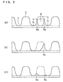
- Fig. 2 shows schematically cross sections of three substrates having a land-groove structure.
- the light-transmissive substrate to be used in the optical recording medium of the invention is generally indicated by 1 and on this substrate, grooves 3 and lands 2 defined by such grooves 3 are formed alternately in a circumferential direction.
- the light-transmissive substrate 1 having such a land-groove structure is overlaid with a recording layer and a reflective layer which, in turn, may optionally be overlaid with a protective layer (the layers are not shown).
- Each of the lands 2 is generally rectangular or trapezoidal in cross section having a top surface 4 and sidewalls 5 and has a height (land height) of h 1 .
- each land 2 has a prepit (land prepit) 6 formed in the center area of the land in a width direction thereof.
- the prepit 6 is formed in such a way that the lower part of each sidewall 5 of the land is left intact with a specified height (h 2 ) to form a boundary wall 5a between the prepit and the adjacent groove 3.
- the ratio of the height of the boundary wall 5a, which is equal to the residual land height (h 2 ), to the land height (h 1 ) is 0.25 - 0.80 (on average).
- the prepit 6 is not offset in the land but is formed in the center area of the land 2 in a width direction thereof and, as a result, such prepit can be formed that has boundary walls 5a, 5a of substantially the same height each other.
- the heights of the two boundary walls 5a, 5a are preferably the same or the difference should be as small as possible. Considering the actual manufacturing practices, it is preferred for the purposes of the invention that the difference between the heights of the two boundary walls 5a, 5a is held within the range of from zero to ⁇ 20%.
- the height (h 1 ) of the land 2 represents the difference in height between the bottom surface of the groove 3 and the top surface 4 of the land 2.
- the height of boundary wall 5a (h 2 ) defining prepit 6 represents the difference in height between the bottom surface of the groove 3 and the top edge of the sidewall 5a of the remaining part of the land.
- the prepit 6 is usually formed in such a way that its bottom surface is generally flush with the bottom surface of the groove 3, so the height (h 2 ) of the boundary wall 5a is substantially the same as the difference in height between the bottom surface of the prepit 6 and the top edge of the sidewall 5a of the remaining part of the land.
- the land between two wobbled grooves varies slightly in width. This can cause variations in the position of prepits to such an extent that they depart somewhat from the desired position which is in the center area of the land in a width direction thereof. Even in this case, the two boundary walls 5a should have a height 0.25 - 0.80 times the height of the land.
- the ratio of h 2 /h 1 is preferably 0.35 - 0.80, more preferably 0.45 - 0.75.
- a prepit is not defined by boundary walls, it will connect to adjacent grooves and prepit signals will cause undesirably large effects on the quality of the signals recorded in the grooves, whereby causing errors in reproducing signals to result in uncorrectable error.
- the recorded signals are video signals, "uncorrectable error” means skipping of a portion of the desired image to produce a mosaic pattern or an erratic playback operation which in the worst case will stop completely.
- any prepit defining boundary walls have heights less than 0.25 times the height of the land, undesirably large effects will be caused on record/playback signals as is the case of having no boundary walls. If the height of the boundary walls is greater than 0.80 times the height of the land, the output of prepit signals decreases so much that if the prepits are short in length, consistent detection of address signals is difficult.
- the prepits in a land are operatively associated with either of two grooves adjacent to the land. For example, data are recorded into the groove by causing a laser beam to track it while detecting address information from the prepits in the land adjacent to either side of the groove.
- an optical recording medium that records groove signals while detecting prepit signals from a land that locates at inner side of the groove in a radius direction of a disc.
- a laser beam is spot irradiated. If a prepit is off-centered or offset at inner area of the land in a radius direction of the disc, the position of the prepit in the land, said prepit is required in recording groove signals, is away from the groove by a distance equal to that offset, and that the area of detection prepit occupied in the laser-spot-irradiated area decreases by the corresponding offset amount, making it difficult to detect prepit signals effectively so that address information can be read only inconsistently during recording to cause adverse effects on the recording operation.
- the aforesaid groove i.e., the groove that adjacent to inner side of the land in a radius direction, is closer to the groove by a distance equal to that offset; although the output of prepit signals is adequate, the area of non-detection prepit occupied in the laser-spot-irradiated area increases, and pits are incompletely formed into which the groove signals are to be recorded, making it difficult to accurately reproduce signals from pits.
- the prepits in the land adjacent to the other side of the land i.e., inner side of the land, said prepit is not required to detect signals, is away from the recording groove, and therefore said non-detection prepit will cause no adverse effects during recording.
- a boundary wall is formed on only one side of the land and in Fig. 2(c), the boundary walls on both sides of the land are unduly low in height; either case shows the formation of land prepits in optical recording media which are outside the scope of the present invention and the intended advantages of the invention cannot of course be attained.
- the length of prepits to be formed is not limited to any particular value but it is preferably less than 3T, more preferably in a range of about 1T - 2T [T: (1/channel bit rate) x the reference linear velocity].
- the optical recording medium according to the first embodiment of the invention by forming prepits satisfying the stated height requirement in a land in an area at the center in a width direction thereof, the inconveniences caused in the prior art due to the formation of land prepits in offset positions are eliminated, and groove signals of high quality can be recorded and reproduced while making it possible to reproduce high-quality signals from the prepits.
- prepits having smaller width than a land are formed in the land in its central area in such a way that boundary walls are substantially equal in height to the land, not only is it difficult to make a stamper as a prepit forming mold but the moldability of prepits is also limited to lower the production rate of the optical recording medium. As a further problem, small prepits can lead to the reproduction of lower-quality signals from the prepits. These inconveniences are eliminated by the present invention.
- the light-transmissive substrate which has prepits formed in the manner described above and which is to be used in an optical recording medium according to the first embodiment of the invention can be prepared by any known techniques. A preferred procedure is described below.
- a photoresist layer (about 0.2 ⁇ m thick) is provided onto a glass disc about 0.6 mm thick and selectively irradiated a laser beam thereto. Stated specifically, a cutting laser beam is passed through a half-mirror so that it is split into two beamlets that will focus at different positions.
- a cutting laser beam is passed through a half-mirror so that it is split into two beamlets that will focus at different positions.
- one beamlet is supplied with wobble signals and used to form grooves and the other beamlet is supplied with input signals for land prepit formation. Using these beamlets, one can pattern the photoresist layer to form grooves and land prepits simultaneously.
- a conductive metal film is formed on the disc surface by sputtering or some other suitable method.
- a metal layer such as Ni layer is provided onto the conductive film and later stripped from the glass disc.
- post-treatments including removal of the unwanted photoresist layer, the glass disc is blanked in a specified shape to make a stamper.
- a transparent resin is injection molded or a light-transmissive member is processed by the 2P method to produce a light-transmissive substrate having grooves and land prepits formed in a specified pattern.
- Transparent resins may be thermoplastic and exemplified by polycarbonates and polyolefins. Care must be taken to insure that the resin temperature or the mold temperature is not unduly low or that the mold opening/closing pressure is not unduly small; otherwise, the resin moldability decreases to such an extent that the resin will not flow sufficiently to fill every fine details of the stamper and the height of boundary walls between land and groove will fluctuate, making it difficult to insure the desired value.
- the shape and other features of land prepits contribute much to the production of a stamper, so the spot diameter and quantity of the exposing laser beam used to cut a prepit pattern into the photoresist layer must be adjusted with close tolerances to make a stamper having the desired prepit pattern.
- a prepit pattern can positively be formed in an inter-groove land at the center area in a width direction thereof.
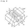
- Fig. 3 shows schematically the essential part of a light-transmissive substrate to be used in an optical recording medium according to the second embodiment of the invention.
- grooves 3 and lands 2 defined by such grooves 3 are formed alternately on a light-transmissive substrate 1 in a circumferential direction.
- the light-transmissive substrate 1 having such a land-groove structure is overlaid with a recording layer and a reflective layer which, in turn, may optionally be overlaid with a protective layer (the layers are not shown).
- Each of the lands 2 is generally rectangular or trapezoidal in cross section having a top surface 4 and sidewalls 5 and has a height (land height) of h 1 .
- Each land 2 has a prepit (land prepit) 6 formed in the center area of the land in a width direction thereof.
- the prepit 6 is formed in such a way that its length L 1 , or the length in peripheral direction in which the medium rotates, is no less than 3T [T: (1/channel bit rate) x the reference linear velocity].
- the prepit 6 is formed in such a way that a boundary wall 5a exists to separate it from the adjacent groove 3 on each side.
- the height of the boundary wall 5a is not limited to any particular value but in the present invention, the ratio of its height h 2 to the land height h 1 is preferably greater than 0.80.
- the key parameter T in the definition of the prepit length L 1 means the reciprocal of the channel bit rate.
- the channel bit rate is typically 26.16 Mbps and its reciprocal is 38.226 ns which is defined as 1T.
- T depends on the linear velocity in the record/playback mode (which is commonly called the "reference linear velocity").
- Current models of DVD-R have two capacities, 3.95 GB and 4.7 GB, for the same disc area.
- the 3.95 GB disc has a reference linear velocity of 3.84 m/s and the value of 1T as calculated by 3.84 x 38.226 (nm) is about 0.1468 ⁇ m; hence, the value of 3T is about 0.44 ⁇ m.
- the 4.7 GB disc has a reference linear velocity of 3.49 m/s and the value of 1T as calculated by 3.49 x 38.226 (nm) is about 0.13334 ⁇ m; hence, the value of 3T is about 0.40 ⁇ m.
- land prepits are formed on the 3.95 GB disc such that their length L 1 is at least about 0.44 ⁇ m and in the case of the 4.7 GB disc, L 1 is at least about 0.40 ⁇ m.
- prepits are formed in such a length as to enable the recording of 2T signals which form the shortest pit. Therefore, the length of conventional prepits has been approximately equal to or slighter greater than 2T.
- the height of the boundary wall h 2 is equal to the height of the land h 1 . Adjusting the height of the boundary wall to be equal to the height of the land is ideal for the purpose of recording and reproducing groove signals accurately.
- high boundary walls prevent the reproduction of high-quality prepit signals and the signals reproduced from the prepits deteriorate in quality. The need to form small land prepits is another factor in deteriorating the quality of signals reproduced from the land prepits.
- land prepits are formed to be longer than 3T and this solves the aforementioned problems of the prior art due to the adjustment of prepit length to about 2T and prepit signals of high quality can be reproduced even if the boundary wall of each prepit between land and each adjacent groove is as high as the land and even if the prepit width is small.
- the upper limit of land prepit length L 1 is not limited to any particular value as long as it is 3T or more. As the prepit length increases, it becomes easier to detect reproduction signals from the prepit. However, if the prepit is unduly long, there is an increased chance for the occurrence of crosstalk with recorded signals in adjacent grooves and an offset in phase from wobbling is also likely to occur. To the extent that no such inconveniences occur, the length of land prepits has no particular upper limit.
- the height of boundary walls need not be the same as the land height. Consistent detection of prepit signals and effective recording and reproduction of groove signals can be accomplished if h 2 /h 1 is greater than 0.8. In other words, the intended advantages of the invention can still be attained even if the upper edge of a land is nicked in the process of forming prepits.
- the height (h 1 ) of the land 2 represents the difference in height between the bottom surface of the groove 3 and the top surface 4 of the land 2.
- the height of boundary wall 5a (h 2 ) defining prepit 6 represents the difference in height between the bottom surface of the groove 3 and the top edge of the sidewall 5a of the remaining part of the land.
- the prepit 6 is usually formed in such a way that its bottom surface is generally flush with the bottom surface of the groove 3, so the height (h 2 ) of the boundary wall 5a is substantially the same as the difference in height between the bottom surface of the prepit 6 and the top edge of the sidewall 5a of the remaining part of the land.
- the land between two wobbled grooves varies slightly in width. This can cause variations in the position of prepits to such an extent that they depart somewhat from the desired position which is at the center area of the land in a width direction thereof. Even in this case, the prepit length should not be smaller than 3T and the two boundary walls 5a have preferably a height more than 0.80 times the height of the land.
- a prepit is not defined by boundary walls, it will connect to adjacent grooves and prepit signals will cause undesirably large effects on the quality of the signals recorded in the grooves, whereby causing errors in reproducing signals to result in uncorrectable error.
- the recorded signals are video signals, "uncorrectable error” means skipping of a portion of the desired image to produce a mosaic pattern or an erratic playback operation which in the worst case will stop completely.
- optical recording medium enables consistent detection of address information even if the height of boundary walls is substantially equal to the land height.
- prepits are formed in a land in an area which is generally at the center of its width to leave boundary walls intact on both sides of the land at a height preferably almost equal to the land height and over a length (L 1 ) greater than 3T.
- L 1 length
- the present invention thus eliminates the problems with the conventional practice of forming short prepits (e.g., deterioration in the quality of prepit signals reproduced).
- a light-transmissive substrate which has prepits formed in the manner described above and which is to be used in an optical recording medium according to the second embodiment of the invention can be prepared by the same procedure as used to make the light-transmissive substrate for the optical recording medium according to the first embodiment.
- the thus prepared light-transmissive substrate having a land-groove structure is subsequently overlaid with a recording layer.
- a recording layer There is no particular limitation on the recording layer and any types can be employed, including an organic dye based recording layer and a phase-change based recording layer.
- organic dye based recording layer In forming the organic dye based recording layer, common organic dye components which are conventionally used in this type of recording layer can be employed, as exemplified by cyanine dyes, phthalocyanine dyes and azo dyes.
- organic dyes having a maximum absorption wavelength ( ⁇ max ) of 400 - 700 nm in thin film are preferably used either alone or in combination. Most of these are dye components used in DVD-R and other members of the DVD family to perform data recording and reproduction from the recording layer.
- maximum absorption wavelength ( ⁇ max ) in thin film means a maximum absorption wavelength as measured for a particular organic dye after it is formed in a thin-film recording layer.
- Maximum absorption spectra of dyes in thin film behave differently than maximum absorption spectra in solution having the same dyes dissolved in a solvent.
- a dye of interest is dissolved in an organic solvent at a concentration of 1 - 20 wt% and the solution is spin coated onto a groove- or pit-less flat PC plate to form a film about 60 - 200 nm thick with care being taken not to provide any particular orientation and the applied film is dried at 50 - 70 °C.
- the organic solvent is preferably of a type that is capable of dissolving the dye and which has a boiling point of 50 - 150 °C in air atmosphere. If the dye undergoes excessive crystallization or association as the solvent evaporates during spin coating, a different solvent should be chosen.
- the organic dye component to be used in the present invention is at least one member of the group essentially consisting of trimethinecyanine dyes represented by the following general formula (I) and dye-metal chelate compounds (metal-containing azo dyes) represented by the following general formula (II) wherein the respective symbols have the following definitions :
- trimethinecyanine dye represented by the general formula (I) a compound represented by the following formula (XVIII) may specifically be mentioned:
- the metal is preferably mono- or divalent and specific examples include Ni, V, Cu and Zn.
- the chelate compound (metal-containing azo dye) may, taken as a whole, be negatively charged. If this is anticipated, forming a salt with an alkali metal such as Na + or a positively charged dye such as rhodamine dye, triphenylmethane dye or trimethinecyanine dye is preferred from such viewpoints as the electrical characteristics and lightfastness of the disc.
- a compound represented by the following formula (XIX) may specifically be mentioned:
- the organic dye component described above is dissolved in a suitable solvent and the solution is spin coated to the light-transmissive substrate and dried to form an organic dye layer having the desired thickness.
- the dye layer can also be formed by methods other than spin coating, as exemplified by spray coating, screen printing, dipping and even vapor deposition.
- the thickness of the dye layer to be formed should be determined as appropriate for the dye used.
- the dye component is dissolved in a solvent to form an applicable organic dye solution.
- the solvent to be used should be capable of dissolving the dye adequately while causing no adverse effects on the light-transmissive substrate.
- the concentration of the dye component in the solution is preferably in the range of about 0.01 - 10 wt%.
- Exemplary solvents include: alcoholic solvents, such as methanol, ethanol, isopropylalcohol, octafluoropentanol, allyl alcohol, methyl cellosolve, ethyl cellosolve and tetrafluoropropanol; aliphatic or alicyclic hydrocarbon solvents, such as hexane, heptane, octane, decane, cyclohexane, methylcyclohexane, ethylcyclohexane and dimethylcyclohexane; aromatic hydrocarbon solvents, such as toluene, xylene and benzene; halogenated hydrocarbon solvents, such as carbon tetrachloride, chloroform, tetrachloroethane and dibromoethane; ether solvents, such as diethyl ether, dibutyl ether, diisopropyl ether and dioxan
- the thickness of the organic dye layer is not limited to any particular value and it is preferably in the range of about 10 - 300 nm, more preferably of about 60 - 250 nm.
- the organic dye layer is then overlaid with a reflective layer.
- the reflective layer is made of a material capable of reasonably high reflection at the wavelength of reproducing light, as exemplified by Au, Ag, Cu, A1, Ni, Pd, Cr and Pt. These elements may be used either independently or in alloy form.
- the following metals and semimetals may additionally be contained in the reflective layer: Mg, Se, Hf, V, Nb, Ru, W, Mn, Re, Fe, Co, Rh, Ir, Zn, Cd, Ga, In, Si, Ge, Te, Pb, Po, Sn and Bi.
- the reflective layer may be formed by various methods including sputtering, ion plating, chemical vapor deposition and vacuum evaporation but these are not the only methods that can be employed.
- a known inorganic or organic intermediate layer or adhesive layer may be provided on top of the substrate or under the reflective layer.
- the thickness of the reflective layer is not limited to any particular value and is preferably in the range of about 10 - 300 nm, more preferably about 80 - 200 nm.
- the reflective layer is usually overlaid with a protective layer.
- a protective layer may be formed of any materials including organics and inorganics.
- Exemplary organic materials include thermoplastic resins, thermosetting resins and UV curable resins.
- Exemplary inorganic materials include SiO 2 , SiN 4 , MgF 2 and SnO 2 .
- Thermoplastic and thermosetting resins are dissolved in suitable solvents to form coating solutions which are applied and dried to form the protective layer.
- UV curable resins are applied either on their own or in the form of a coating solution in a suitable solvent and then cured by irradiation with UV light.
- Exemplary UV curable resins are acrylate resins such as urethane acrylate, epoxy acrylate and polyester acrylate. These materials may be used either independently or in admixture.
- the protective layer may consist of one or more sub-layers.
- the protective layer may be formed by coating techniques such as spin coating and casting, as well as non-coating techniques such as sputtering and chemical vapor deposition.
- the protective layer may also be applied to the side of the light-transmissive substrate on which light is incident.
- the recording layer is of a type that performs recording by phase change
- known phase-change based recording materials such as a Ag-In-Sb-Te system and a Ge-Te-Sb system may be used to form a multi-layered structure on the light-transmissive substrate which comprises a dielectric layer, a barrier layer, a (phase-change) based recording layer, a dielectric layer and a reflective layer.
- the recording layer is overlaid with an organic protective layer formed of a UV curable acrylic resin.
- the bonding adhesive may be a hot-melt adhesive, a UV curable adhesive, a heat-curable adhesive and a pressure-sensitive adhesive and using these adhesives, two discs are bonded together by suitable methods such as roll coating, screen printing and spin coating.
- suitable methods such as roll coating, screen printing and spin coating.
- overall considerations including operating efficiency, production rate and disc characteristics dictate bonding two discs by screen printing or spin coating using a UV curable adhesive.
- the optical recording medium rotating at a constant linear or angular velocity is irradiated with recording light such as a semiconductor laser beam that is applied from the substrate side. This irradiation with the recording light changes the reflectance of light from the recording layer.
- a semiconductor laser beam having a wavelength in the range of 400 - 660 nm is used as the recording light.
- the optical recording medium while rotating at a constant linear or angular velocity is irradiated with the semiconductor laser beam that is applied from the substrate side and the difference in the quantity of reflected light is detected.
- prepits having boundary walls of a specified height are formed in a land in an area generally at the center of its width and this eliminates the inconveniences experienced when prepits were formed in an area offset toward either side of the land; as a result, prepit signals can be detected consistently and even if high-density recording is done, data signals can be reproduced effectively without errors.
- the light-transmissive substrates used in the following examples and comparative examples were prepared by known methods using an argon laser in such a way that the main beam cut prepits into lands in operative association with the cutting of grooves by the sub-beam. Adjustment of the main beam's power varied the amount of exposure and, hence, the height of boundary walls on opposite sides of each land prepit. The length of prepits was varied by adjusting the duration of exposure time.
- PI error evaluation was performed. Using DDU-1000 (Pulsetec Industrial Co., Ltd.), EFM+ signals (8-16 signals) were recorded to each sample of optical recording medium with an optimum recording laser power (Po) at a linear velocity of 3.5 m/sec and the results were evaluated by averaging five measurements. To decode PI errors, M-5298E (Kenwood Corp.) was used.
- a polycarbonate disc of 120 mm diameter, 0.6 mm thick having wobbled tracking grooves and prepits that were formed in the lands defined by the grooves was used as a light-transmissive substrate.
- the land prepits were formed in such a way that the height (h 2 ) of the boundary walls on opposite sides was 0.45 times as large as the height of the land (h 1 ).
- a trimethinecyanine dye represented by the formula (XVIII) and a metal-containing azo dye represented by the formula (XIX) were mixed in proportions of 4:6 and dissolved in tetrafluoropropanol to make a 4% coating solution, which was spin coated to the light-transmissive substrate to give a dry thickness of 80 nm.
- a Ag layer was formed in an average thickness of 190 nm by sputtering with dc magnetron sputter equipment, CD-Coat 1200 (Shibaura Co., Ltd.)
- the light reflecting layer was spin coated with a UV curing agent SD-318 (Dainippon Ink and Chemicals, Inc.) to give a thickness of 6 ⁇ m and the applied coating was cured by irradiation with UV irradiation equipment to form a protective layer.
- SD-318 Dainippon Ink and Chemicals, Inc.
- An additional disc was prepared by superposing the light-transmissive substrate with an organic dye based recording layer, light reflecting layer and protective layer in the manner described above. After coating the protective layer of each disc with a UV curing resin SK7000 (Sony Chemical Corporation) by screen printing, the two discs were bonded together, with their protective layers facing each other as they were exposed to UV light. This completes the process of fabricating an optical recording medium.
- SK7000 Synchronization Chemical Corporation
- An optical recording medium was fabricated by repeating the procedure of Example 1, except that the height of the boundary walls on opposite sides of each land prepit was 0.25 times the height of the land.
- An optical recording medium was fabricated by repeating the procedure of Example 1, except that the height of the boundary walls on opposite sides of each land prepit was 0.35 times the height of the land.
- An optical recording medium was fabricated by repeating the procedure of Example 1, except that the height of the boundary walls on opposite sides of each land prepit was 0.75 times the height of the land.
- An optical recording medium was fabricated by repeating the procedure of Example 1, except that the height of the boundary walls on opposite sides of each land prepit was 0.80 times the height of the land.
- An optical recording medium was fabricated by repeating the procedure of Example 1, except that the organic dye based recording layer was replaced by a phase-change based recording layer of a Ag-In-Sb-Te system.
- An optical recording medium was fabricated by repeating the procedure of Example 1, except that the height of the boundary walls on opposite sides of each land prepit was 0.20 times the height of the land.
- An optical recording medium was fabricated by repeating the procedure of Example 1, except that the height of the boundary walls on opposite sides of each land prepit was 0.90 times the height of the land.
- An optical recording medium was fabricated by repeating the procedure of Example 1, except that the height of the outer boundary wall defining the land prepit was 0.45 times the height of the land whereas the height of the inner boundary wall was 0.20 times as large.
- An optical recording medium was fabricated by repeating the procedure of Example 1, except that the height of the outer boundary wall defining the land prepit was 0.20 times the height of the land whereas the height of the inner boundary wall was 0.45 times as large.
- Example 1 Height of Inner boundary wall relative to Land height Height of Outer boundary wall relative to Land height LPP signal characterist ics PI error value (max value)
- Example 1 0.45 0.45 good 50
- Example 2 0.25 0.25 good 135
- Example 3 0.35 0.35 good 90
- Example 4 0.80 0.80 good 25
- Example 5 0.75 0.75 good 30
- Example 6 0.45 0.45 good 10 Comparative Example 1 0.20 0.20 good 450 Comparative Example 2 0.90 0.90 fair 20 Comparative Example 3 0.20 0.45 good 320 Comparative Example 4 0.45 0.20 good 350
- a polycarbonate disc of 120 mm diameter, 0.6 mm thick having wobbled tracking grooves and prepits that were formed in the lands defined by the grooves was used as a light-transmissive substrate.
- the land prepits were formed in such a way that they were 3T long and that the height (h 2 ) of the boundary walls on opposite sides was the same as the height of the land (h 1 ).
- a trimethinecyanine dye represented by the formula (XVIII) and a metal-containing azo dye represented by the formula (XIX) were mixed in proportions of 4:6 and dissolved in tetrafluoropropanol to make a 4% coating solution, which was spin coated to the light-transmissive substrate to give a dry thickness of 70 nm.
- a Ag layer was formed in an average thickness of 190 nm by sputtering with dc magnetron sputter equipment, CD-Coat 1200 (Shibaura Co., Ltd.).
- the light reflecting layer was spin coated with a UV curing agent SD-318 (Dainippon Ink and Chemicals, Inc.) to give a thickness of 6 ⁇ m and the applied coating was cured by irradiation with UV irradiation equipment to form a protective layer.
- SD-318 Dainippon Ink and Chemicals, Inc.
- An additional disc was prepared by superposing the light-transmissive substrate with an organic dye based recording layer, light reflecting layer and protective layer in the manner described above. After coating the protective layer of each disc with a UV curing resin SK7000 (Sony Chemical Corporation) by screen printing, the two discs were bonded together, with their protective layers facing each other as they were exposed to UV light. This completes the process of fabricating an optical recording medium.
- SK7000 Synchronization Chemical Corporation
- An optical recording medium was fabricated by repeating the procedure of Example 7, except that the land prepits were 4T long.
- An optical recording medium was fabricated by repeating the procedure of Example 7, except that the land prepits were 6T long.
- An optical recording medium was fabricated by repeating the procedure of Example 7, except that the land prepits were 2T long.
- An optical recording medium was fabricated by repeating the procedure of Example 7, except that the land prepits were 1T long.
- the present invention provides an optical recording medium which permits address information and disc rotation control information to be accessed accurately even if the track pitch is small and which still can be manufactured efficiently with the added capability of signal recording in high density and reproduction of high-quality signals.
Landscapes
- Chemical & Material Sciences (AREA)
- Organic Chemistry (AREA)
- Engineering & Computer Science (AREA)
- Manufacturing & Machinery (AREA)
- Optical Record Carriers And Manufacture Thereof (AREA)
- Optical Recording Or Reproduction (AREA)
Abstract
There is disclosed an optical recording medium having at
least a recording layer provided on a light-transmissive
substrate having grooves and lands with prepits, wherein said
lands are generally rectangular or trapezoidal in cross
section having a top surface and sidewalls, as well as a
specified land height (h1), and said prepits are formed in a
land in the center area of the land in a width direction
thereof, and spaced from the adjacent grooves by boundary
walls of a specified height (h2). The optical recording
medium permits address information and disc rotation control
information to be accessed accurately even if a track pitch
is small, and which still can be manufactured efficiently,
with the added capability of signal recording in high density
and reproduction of high-quality signals.
Description
This invention relates to an optical recording medium
having a recording layer provided on a substrate having
grooves and lands with prepits. More specifically, the
invention relates to an optical recording medium capable of
reading address information accurately from prepits without
affecting the recording/reproduction of information to/from
the recording layer. The invention is applicable with
particular advantage to recordable optical recording media,
such as DVD-R and DVD-RW.
DVDs or digital versatile discs are optical recording
media that permit digital recording and their common
structure generally comprises a light-transmissive substrate
overlaid with a recording layer, a reflective layer and a
protective layer in that order.
In recordable optical recording media, such as DVD-R and
DVD-RW, the substrate has a land-groove structure, with a
guide groove, commonly referred to simply as a groove, being
formed between adjacent two lands, for recording data signals
using a laser beam. The shapes of lands and grooves are
optimized considering the overall signal quality including
various record/playback characteristics and servo signal
characteristics. Grooves are formed with about 0.6 - 0.8 µm
pitches, and are typically "wobbled" to follow wavy (or
serpentine) paths with a specified cycle. By detecting the
cycle, the disc can be rotated at an accurate linear
velocity.
Lands have pits, more commonly called prepits, formed at
given intervals, and the address information on the disc is
recorded in these pits, thereby permitting the detection of
orientations on the disc even if it is yet blank or
unrecorded. Since the prepits are formed so as to keep a
specified positional relationship with the wobbled grooves,
data signals are recorded to and reproduced from a groove
while detecting the signals from the prepits formed in either
of the two lands adjacent to the groove, for instance, the
outer land adjacent to the groove in a radius direction of
the disc.
In order to ensure that address information from the
prepit is accessed accurately or data signals are effectively
recorded to and reproduced from adjacent grooves even if the
track pitch is small, various R&D efforts have been made
concerning the shape of prepits and the method of forming
them. For example, JP-A-9-326138 and JP-A-2000-149330
disclose optical recording media having prepits formed
cutting out one side of each land to reach either of adjacent
grooves. JP-A-2000-11460 discloses an optical recording
medium having prepits formed in each land at off-centered
position thereof, for instance, at an inner position thereof
in a radius direction of the disc.
However, those approaches above are unsatisfactory in
that prepit signals cause undesirably great effects on groove
signals, causing various problems such as the occurrence of
unreadable errors during reproducing groove signals.
An object, therefore, of the present invention is to
provide an optical recording medium which permits address
information and disc rotation control information to be
accessed accurately even if the track pitch is small, and
which still can be manufactured efficiently, with the added
capability of signal recording in high density and
reproduction of high-quality signals.
The invention attains this object by an optical
recording medium having at least a recording layer provided
on a light-transmissive substrate having grooves and lands
with prepits, wherein said lands are generally rectangular or
trapezoidal in cross section having a top surface and
sidewalls, as well as a specified land height (h1), and said
prepits are formed in a land in the center area of the land
in a width direction thereof, and spaced from the adjacent
grooves by boundary walls of a specified height (h2).
The optical recording medium of the invention is not
limited in any particular way and may be of tape, card, disc
or any other forms that are capable of optical recording.
Most desirably, the invention is applied to DVD-R, DVD-RW and
other recording discs capable of recording information at
high density.
The optical recording medium of the invention uses a
substrate having a land-groove structure and its specific
configuration is determined as appropriate for the required
performance of the medium. Therefore, the invention is
applicable to any types of optical recording medium including
a wobbled type and a non-wobbled type in which the grooves
draw smooth curves in a circumferential direction.
The optical recording medium of the invention uses a
light-transmissive substrate having grooves and lands of a
specified height (h1) with prepits, and is characterized in
that said prepits are formed in the center area of the land
in a width direction thereof, and are separated from the
adjacent grooves by boundary walls of a specified height
(h2).
The optical recording medium of this invention is
described below in detail by showing its first embodiment in
Figs. 1 and 2 and its second embodiment in Fig. 3. It
should, however, be noted that the invention is by no means
intended to those embodiments.
Fig. 1 shows schematically the essential part of a
light-transmissive substrate to be used in an optical
recording medium according to the first embodiment of the
invention. Fig. 2 shows schematically cross sections of
three substrates having a land-groove structure.
In Fig. 1, the light-transmissive substrate to be used
in the optical recording medium of the invention is generally
indicated by 1 and on this substrate, grooves 3 and lands 2
defined by such grooves 3 are formed alternately in a
circumferential direction. The light-transmissive substrate
1 having such a land-groove structure is overlaid with a
recording layer and a reflective layer which, in turn, may
optionally be overlaid with a protective layer (the layers
are not shown).
Each of the lands 2 is generally rectangular or
trapezoidal in cross section having a top surface 4 and
sidewalls 5 and has a height (land height) of h1.
In the present invention, each land 2 has a prepit (land
prepit) 6 formed in the center area of the land in a width
direction thereof. In the optical recording medium according
to the first embodiment of the invention, the prepit 6 is
formed in such a way that the lower part of each sidewall 5
of the land is left intact with a specified height (h2) to
form a boundary wall 5a between the prepit and the adjacent
groove 3. The ratio of the height of the boundary wall 5a,
which is equal to the residual land height (h2), to the land
height (h1) is 0.25 - 0.80 (on average). By adjusting the
value of h2/h1 to lie within the aforementioned range, prepit
signals can be detected consistently and groove signals can
be recorded and reproduced effectively.
The values of h1 which is the land height, and h2, or the
height of the residual land (i.e., the boundary wall 5a
between prepit and groove), must satisfy the relation of h2/h1
= 0.25 - 0.80 (on average) and this means that the two
boundary walls 5a, 5a facing the grooves 3, 3 adjacent the
land 2 must both have a height 0.25 - 0.80 times the land
height (h1).
In the present invention, the prepit 6 is not offset in
the land but is formed in the center area of the land 2 in a
width direction thereof and, as a result, such prepit can be
formed that has boundary walls 5a, 5a of substantially the
same height each other. In order to detect prepit signals
consistently or to reproduce groove signals of high quality,
the heights of the two boundary walls 5a, 5a are preferably
the same or the difference should be as small as possible.
Considering the actual manufacturing practices, it is
preferred for the purposes of the invention that the
difference between the heights of the two boundary walls 5a,
5a is held within the range of from zero to ± 20%.
In the present invention, the height (h1) of the land 2
represents the difference in height between the bottom
surface of the groove 3 and the top surface 4 of the land 2.
The height of boundary wall 5a (h2) defining prepit 6
represents the difference in height between the bottom
surface of the groove 3 and the top edge of the sidewall 5a
of the remaining part of the land. The prepit 6 is usually
formed in such a way that its bottom surface is generally
flush with the bottom surface of the groove 3, so the height
(h2) of the boundary wall 5a is substantially the same as the
difference in height between the bottom surface of the prepit
6 and the top edge of the sidewall 5a of the remaining part
of the land.
In the case of a disc having wobbled grooves, the land
between two wobbled grooves varies slightly in width. This
can cause variations in the position of prepits to such an
extent that they depart somewhat from the desired position
which is in the center area of the land in a width direction
thereof. Even in this case, the two boundary walls 5a should
have a height 0.25 - 0.80 times the height of the land.
The ratio of h2/h1 is preferably 0.35 - 0.80, more
preferably 0.45 - 0.75.
If a prepit is not defined by boundary walls, it will
connect to adjacent grooves and prepit signals will cause
undesirably large effects on the quality of the signals
recorded in the grooves, whereby causing errors in
reproducing signals to result in uncorrectable error. If the
recorded signals are video signals, "uncorrectable error"
means skipping of a portion of the desired image to produce a
mosaic pattern or an erratic playback operation which in the
worst case will stop completely.
If any prepit defining boundary walls have heights less
than 0.25 times the height of the land, undesirably large
effects will be caused on record/playback signals as is the
case of having no boundary walls. If the height of the
boundary walls is greater than 0.80 times the height of the
land, the output of prepit signals decreases so much that if
the prepits are short in length, consistent detection of
address signals is difficult.
When data signals are recorded to an optical recording
medium having a land-groove structure, the prepits in a land
are operatively associated with either of two grooves
adjacent to the land. For example, data are recorded into
the groove by causing a laser beam to track it while
detecting address information from the prepits in the land
adjacent to either side of the groove.
Therefore, if prepits are off-centered at either inner
or outer area of the land in a radius direction of the disc,
signals to be recorded in a groove adjacent to one side of
the land toward which side the prepits are offset, are
affected by the prepits so greatly that only incomplete pits
are formed in the groove and playback signals from the groove
are affected by an undesirably large degree.
Consider, for example, an optical recording medium that
records groove signals while detecting prepit signals from a
land that locates at inner side of the groove in a radius
direction of a disc.
To record groove signals, a laser beam is spot
irradiated. If a prepit is off-centered or offset at inner
area of the land in a radius direction of the disc, the
position of the prepit in the land, said prepit is required
in recording groove signals, is away from the groove by a
distance equal to that offset, and that the area of detection
prepit occupied in the laser-spot-irradiated area decreases
by the corresponding offset amount, making it difficult to
detect prepit signals effectively so that address information
can be read only inconsistently during recording to cause
adverse effects on the recording operation. A further
problem arises from the fact that a prepit formed in the
other land adjacent to the other side of the groove, i.e.,
outer land, which is not required for signal detection is
formed in an offset position closer to the recording groove
of interest, and therefore, the area of non-detection prepit
occupied in the laser-spot-irradiated area increases by the
corresponding offset amount, and pits are incompletely formed
into which the groove signals are to be recorded, making it
difficult to accurately reproduce signals from pits.
If a prepit is off-centered or offset at outer area of
the land in a radius direction of the disc, the aforesaid
groove, i.e., the groove that adjacent to inner side of the
land in a radius direction, is closer to the groove by a
distance equal to that offset; although the output of prepit
signals is adequate, the area of non-detection prepit
occupied in the laser-spot-irradiated area increases, and
pits are incompletely formed into which the groove signals
are to be recorded, making it difficult to accurately
reproduce signals from pits. It should, however, be noted
that the prepits in the land adjacent to the other side of
the land, i.e., inner side of the land, said prepit is not
required to detect signals, is away from the recording
groove, and therefore said non-detection prepit will cause no
adverse effects during recording.
To form prepits in a land such that the boundary walls
of each prepit have the same height as the land is ideal for
the purpose of recording and reproducing groove signals
accurately. In such cases, however, the prepit width has to
be reduced and this causes various problems in the
fabrication of discs such as the limitations of irradiation
of laser beam during exposure in the making of a master disc
and the difficulty involved in forming prepits of the
intended shape. These difficulties increase with increasing
recording density.
Considering these facts, the optical recording medium
shown in Fig. 2(a) forms a prepit 6 in a land 3 in such a way
that a boundary wall 5a on each side of the land satisfies
the relation of h2/h1 = 0.25 - 0.80, and as a result,
satisfactory signal reproduction is performed to bring about
the intended advantages of the invention. In Fig. 2(b), a
boundary wall is formed on only one side of the land and in
Fig. 2(c), the boundary walls on both sides of the land are
unduly low in height; either case shows the formation of land
prepits in optical recording media which are outside the
scope of the present invention and the intended advantages of
the invention cannot of course be attained.
In the optical recording medium according to the first
embodiment of the invention, the length of prepits to be
formed is not limited to any particular value but it is
preferably less than 3T, more preferably in a range of about
1T - 2T [T: (1/channel bit rate) x the reference linear
velocity].
Thus, in the optical recording medium according to the
first embodiment of the invention, by forming prepits
satisfying the stated height requirement in a land in an area
at the center in a width direction thereof, the
inconveniences caused in the prior art due to the formation
of land prepits in offset positions are eliminated, and
groove signals of high quality can be recorded and reproduced
while making it possible to reproduce high-quality signals
from the prepits.
If prepits having smaller width than a land are formed
in the land in its central area in such a way that boundary
walls are substantially equal in height to the land, not only
is it difficult to make a stamper as a prepit forming mold
but the moldability of prepits is also limited to lower the
production rate of the optical recording medium. As a
further problem, small prepits can lead to the reproduction
of lower-quality signals from the prepits. These
inconveniences are eliminated by the present invention.
The light-transmissive substrate which has prepits
formed in the manner described above and which is to be used
in an optical recording medium according to the first
embodiment of the invention can be prepared by any known
techniques. A preferred procedure is described below.
A photoresist layer (about 0.2 µm thick) is provided
onto a glass disc about 0.6 mm thick and selectively
irradiated a laser beam thereto. Stated specifically, a
cutting laser beam is passed through a half-mirror so that it
is split into two beamlets that will focus at different
positions. By means of an optical modulator, one beamlet is
supplied with wobble signals and used to form grooves and the
other beamlet is supplied with input signals for land prepit
formation. Using these beamlets, one can pattern the
photoresist layer to form grooves and land prepits
simultaneously.
After developing the pattern, a conductive metal film is
formed on the disc surface by sputtering or some other
suitable method. A metal layer such as Ni layer is provided
onto the conductive film and later stripped from the glass
disc. After post-treatments including removal of the
unwanted photoresist layer, the glass disc is blanked in a
specified shape to make a stamper.
Using the stamper, a transparent resin is injection
molded or a light-transmissive member is processed by the 2P
method to produce a light-transmissive substrate having
grooves and land prepits formed in a specified pattern.
Transparent resins may be thermoplastic and exemplified by
polycarbonates and polyolefins. Care must be taken to insure
that the resin temperature or the mold temperature is not
unduly low or that the mold opening/closing pressure is not
unduly small; otherwise, the resin moldability decreases to
such an extent that the resin will not flow sufficiently to
fill every fine details of the stamper and the height of
boundary walls between land and groove will fluctuate, making
it difficult to insure the desired value.
As will be understood from the above, the shape and
other features of land prepits contribute much to the
production of a stamper, so the spot diameter and quantity of
the exposing laser beam used to cut a prepit pattern into the
photoresist layer must be adjusted with close tolerances to
make a stamper having the desired prepit pattern. In
addition, by proper adjustment of the optical axis, a prepit
pattern can positively be formed in an inter-groove land at
the center area in a width direction thereof.
Fig. 3 shows schematically the essential part of a
light-transmissive substrate to be used in an optical
recording medium according to the second embodiment of the
invention. As is clear from Fig. 3, grooves 3 and lands 2
defined by such grooves 3 are formed alternately on a light-transmissive
substrate 1 in a circumferential direction. The
light-transmissive substrate 1 having such a land-groove
structure is overlaid with a recording layer and a reflective
layer which, in turn, may optionally be overlaid with a
protective layer (the layers are not shown).
Each of the lands 2 is generally rectangular or
trapezoidal in cross section having a top surface 4 and
sidewalls 5 and has a height (land height) of h1.
Each land 2 has a prepit (land prepit) 6 formed in the
center area of the land in a width direction thereof. In the
optical recording medium according to the second embodiment
of the invention, the prepit 6 is formed in such a way that
its length L1, or the length in peripheral direction in which
the medium rotates, is no less than 3T [T: (1/channel bit
rate) x the reference linear velocity].
Preferably, the prepit 6 is formed in such a way that a
boundary wall 5a exists to separate it from the adjacent
groove 3 on each side. The height of the boundary wall 5a is
not limited to any particular value but in the present
invention, the ratio of its height h2 to the land height h1 is
preferably greater than 0.80. The upper limit of h2/h1 is
preferably equal to one (i.e., h2 = h1).
The key parameter T in the definition of the prepit
length L1 means the reciprocal of the channel bit rate. In
the DVD family, the channel bit rate is typically 26.16 Mbps
and its reciprocal is 38.226 ns which is defined as 1T.
The value of T depends on the linear velocity in the
record/playback mode (which is commonly called the "reference
linear velocity"). Current models of DVD-R have two
capacities, 3.95 GB and 4.7 GB, for the same disc area.
The 3.95 GB disc has a reference linear velocity of 3.84
m/s and the value of 1T as calculated by 3.84 x 38.226 (nm)
is about 0.1468 µm; hence, the value of 3T is about 0.44 µm.
The 4.7 GB disc has a reference linear velocity of 3.49
m/s and the value of 1T as calculated by 3.49 x 38.226 (nm)
is about 0.13334 µm; hence, the value of 3T is about 0.40 µm.
Therefore, according to the invention, land prepits are
formed on the 3.95 GB disc such that their length L1 is at
least about 0.44 µm and in the case of the 4.7 GB disc, L1 is
at least about 0.40 µm.
Conventionally, prepits are formed in such a length as
to enable the recording of 2T signals which form the shortest
pit. Therefore, the length of conventional prepits has been
approximately equal to or slighter greater than 2T.
If prepits are formed in a land at the center area in a
width direction thereof such that the prepit width does not
exceed the land width but two sides of it remain intact to
define a boundary wall between the prepit and each adjacent
groove, the height of the boundary wall h2 is equal to the
height of the land h1. Adjusting the height of the boundary
wall to be equal to the height of the land is ideal for the
purpose of recording and reproducing groove signals
accurately. On the other hand, high boundary walls prevent
the reproduction of high-quality prepit signals and the
signals reproduced from the prepits deteriorate in quality.
The need to form small land prepits is another factor in
deteriorating the quality of signals reproduced from the land
prepits.
In the optical recording medium according to the second
embodiment of the invention, land prepits are formed to be
longer than 3T and this solves the aforementioned problems of
the prior art due to the adjustment of prepit length to about
2T and prepit signals of high quality can be reproduced even
if the boundary wall of each prepit between land and each
adjacent groove is as high as the land and even if the prepit
width is small.
In the present invention, the upper limit of land prepit
length L1 is not limited to any particular value as long as
it is 3T or more. As the prepit length increases, it becomes
easier to detect reproduction signals from the prepit.
However, if the prepit is unduly long, there is an increased
chance for the occurrence of crosstalk with recorded signals
in adjacent grooves and an offset in phase from wobbling is
also likely to occur. To the extent that no such
inconveniences occur, the length of land prepits has no
particular upper limit.
In the present invention, the height of boundary walls
need not be the same as the land height. Consistent
detection of prepit signals and effective recording and
reproduction of groove signals can be accomplished if h2/h1 is
greater than 0.8. In other words, the intended advantages of
the invention can still be attained even if the upper edge of
a land is nicked in the process of forming prepits.
In the present invention, the height (h1) of the land 2
represents the difference in height between the bottom
surface of the groove 3 and the top surface 4 of the land 2.
The height of boundary wall 5a (h2) defining prepit 6
represents the difference in height between the bottom
surface of the groove 3 and the top edge of the sidewall 5a
of the remaining part of the land. The prepit 6 is usually
formed in such a way that its bottom surface is generally
flush with the bottom surface of the groove 3, so the height
(h2) of the boundary wall 5a is substantially the same as the
difference in height between the bottom surface of the prepit
6 and the top edge of the sidewall 5a of the remaining part
of the land.
In the case of a disc having wobbled grooves, the land
between two wobbled grooves varies slightly in width. This
can cause variations in the position of prepits to such an
extent that they depart somewhat from the desired position
which is at the center area of the land in a width direction
thereof. Even in this case, the prepit length should not be
smaller than 3T and the two boundary walls 5a have preferably
a height more than 0.80 times the height of the land.
If a prepit is not defined by boundary walls, it will
connect to adjacent grooves and prepit signals will cause
undesirably large effects on the quality of the signals
recorded in the grooves, whereby causing errors in
reproducing signals to result in uncorrectable error. If the
recorded signals are video signals, "uncorrectable error"
means skipping of a portion of the desired image to produce a
mosaic pattern or an erratic playback operation which in the
worst case will stop completely.
If any prepit defining boundary walls have unduly small
heights compared to the land, undesirably large effects will
be caused on record/playback signals as if there were no
boundary walls at all. The optical recording medium
according to the second embodiment of the invention enables
consistent detection of address information even if the
height of boundary walls is substantially equal to the land
height.
In the optical recording medium according to the second
embodiment of the invention, prepits are formed in a land in
an area which is generally at the center of its width to
leave boundary walls intact on both sides of the land at a
height preferably almost equal to the land height and over a
length (L1) greater than 3T. As a result, groove signals of
high quality can be recorded and reproduced and, in addition,
high-quality signals can be reproduced from prepits. The
present invention thus eliminates the problems with the
conventional practice of forming short prepits (e.g.,
deterioration in the quality of prepit signals reproduced).
A light-transmissive substrate which has prepits formed
in the manner described above and which is to be used in an
optical recording medium according to the second embodiment
of the invention can be prepared by the same procedure as
used to make the light-transmissive substrate for the optical
recording medium according to the first embodiment.
The thus prepared light-transmissive substrate having a
land-groove structure is subsequently overlaid with a
recording layer. There is no particular limitation on the
recording layer and any types can be employed, including an
organic dye based recording layer and a phase-change based
recording layer.
In forming the organic dye based recording layer, common
organic dye components which are conventionally used in this
type of recording layer can be employed, as exemplified by
cyanine dyes, phthalocyanine dyes and azo dyes. In the
present invention, organic dyes having a maximum absorption
wavelength (λmax) of 400 - 700 nm in thin film are preferably
used either alone or in combination. Most of these are dye
components used in DVD-R and other members of the DVD family
to perform data recording and reproduction from the recording
layer.
Speaking of maximum absorption, as long as the optical
media are concerned, absorption spectra in thin film are
important. The term "maximum absorption wavelength (λmax) in
thin film" as used in the invention means a maximum
absorption wavelength as measured for a particular organic
dye after it is formed in a thin-film recording layer.
Maximum absorption spectra of dyes in thin film behave
differently than maximum absorption spectra in solution
having the same dyes dissolved in a solvent.
Maximum absorption spectra in thin film can be measured
by the following non-limiting exemplary method. In the first
step, a dye of interest is dissolved in an organic solvent at
a concentration of 1 - 20 wt% and the solution is spin coated
onto a groove- or pit-less flat PC plate to form a film about
60 - 200 nm thick with care being taken not to provide any
particular orientation and the applied film is dried at 50 -
70 °C. The organic solvent is preferably of a type that is
capable of dissolving the dye and which has a boiling point
of 50 - 150 °C in air atmosphere. If the dye undergoes
excessive crystallization or association as the solvent
evaporates during spin coating, a different solvent should be
chosen. After thusly forming the thin dye film on the flat
PC plate, transmission and absorption spectra are usually
measured with a spectrophotometer.
The organic dye component to be used in the present
invention is at least one member of the group essentially
consisting of trimethinecyanine dyes represented by the
following general formula (I) and dye-metal chelate compounds
(metal-containing azo dyes) represented by the following
general formula (II)
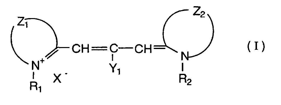
 wherein the respective symbols have the following
definitions :
wherein the respective symbols have the following
definitions :


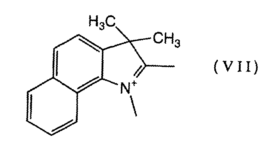


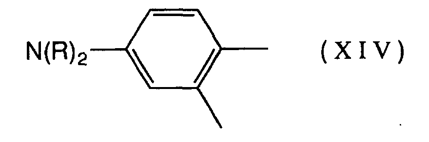

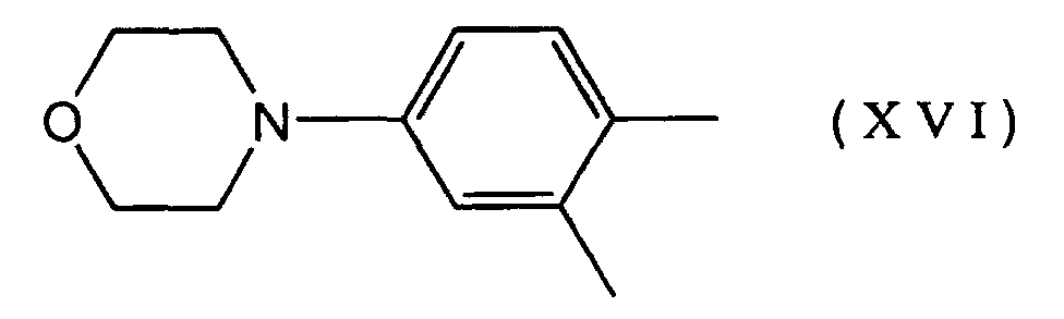

As a preferred example of the trimethinecyanine dye
represented by the general formula (I), a compound
represented by the following formula (XVIII) may specifically
be mentioned:
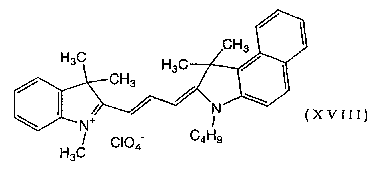
Referring to the dye-metal chelate compound (metal-containing
azo dye) represented by the general formula (II),
the metal is preferably mono- or divalent and specific
examples include Ni, V, Cu and Zn. Depending on the metal
moiety, the chelate compound (metal-containing azo dye) may,
taken as a whole, be negatively charged. If this is
anticipated, forming a salt with an alkali metal such as Na+
or a positively charged dye such as rhodamine dye,
triphenylmethane dye or trimethinecyanine dye is preferred
from such viewpoints as the electrical characteristics and
lightfastness of the disc. As a preferred example of the
dye-metal chelate compound (metal-containing azo dye)
represented by the general formula (II), a compound
represented by the following formula (XIX) may specifically
be mentioned:

The organic dye component described above is dissolved
in a suitable solvent and the solution is spin coated to the
light-transmissive substrate and dried to form an organic dye
layer having the desired thickness. The dye layer can also
be formed by methods other than spin coating, as exemplified
by spray coating, screen printing, dipping and even vapor
deposition. The thickness of the dye layer to be formed
should be determined as appropriate for the dye used.
If spin coating is to be applied, the dye component is
dissolved in a solvent to form an applicable organic dye
solution. The solvent to be used should be capable of
dissolving the dye adequately while causing no adverse
effects on the light-transmissive substrate. The
concentration of the dye component in the solution is
preferably in the range of about 0.01 - 10 wt%.
Exemplary solvents include: alcoholic solvents, such as
methanol, ethanol, isopropylalcohol, octafluoropentanol,
allyl alcohol, methyl cellosolve, ethyl cellosolve and
tetrafluoropropanol; aliphatic or alicyclic hydrocarbon
solvents, such as hexane, heptane, octane, decane,
cyclohexane, methylcyclohexane, ethylcyclohexane and
dimethylcyclohexane; aromatic hydrocarbon solvents, such as
toluene, xylene and benzene; halogenated hydrocarbon
solvents, such as carbon tetrachloride, chloroform,
tetrachloroethane and dibromoethane; ether solvents, such as
diethyl ether, dibutyl ether, diisopropyl ether and dioxane;
ketonic solvents, such as 3-hydroxy-3-methyl-2-butanone;
ester solventsl, such as ethyl acetate and methyl lactate;
and water. From this list, those solvents which do not
attack the substrate material may be chosen and used either
independently or in admixture.
The thickness of the organic dye layer is not limited to
any particular value and it is preferably in the range of
about 10 - 300 nm, more preferably of about 60 - 250 nm.
The organic dye layer is then overlaid with a reflective
layer. The reflective layer is made of a material capable of
reasonably high reflection at the wavelength of reproducing
light, as exemplified by Au, Ag, Cu, A1, Ni, Pd, Cr and Pt.
These elements may be used either independently or in alloy
form. The following metals and semimetals may additionally
be contained in the reflective layer: Mg, Se, Hf, V, Nb, Ru,
W, Mn, Re, Fe, Co, Rh, Ir, Zn, Cd, Ga, In, Si, Ge, Te, Pb,
Po, Sn and Bi.
The reflective layer may be formed by various methods
including sputtering, ion plating, chemical vapor deposition
and vacuum evaporation but these are not the only methods
that can be employed. In order to improve the reflectance
and recording characteristics, a known inorganic or organic
intermediate layer or adhesive layer may be provided on top
of the substrate or under the reflective layer. The
thickness of the reflective layer is not limited to any
particular value and is preferably in the range of about 10 -
300 nm, more preferably about 80 - 200 nm.
The reflective layer is usually overlaid with a
protective layer. Alternatively, two media may be bonded
together. As long as it is capable of protecting the
reflective layer from external forces, the protective layer
may be formed of any materials including organics and
inorganics. Exemplary organic materials include
thermoplastic resins, thermosetting resins and UV curable
resins. Exemplary inorganic materials include SiO2, SiN4,
MgF2 and SnO2. Thermoplastic and thermosetting resins are
dissolved in suitable solvents to form coating solutions
which are applied and dried to form the protective layer. UV
curable resins are applied either on their own or in the form
of a coating solution in a suitable solvent and then cured by
irradiation with UV light. Exemplary UV curable resins are
acrylate resins such as urethane acrylate, epoxy acrylate and
polyester acrylate. These materials may be used either
independently or in admixture. The protective layer may
consist of one or more sub-layers.
As in the case of the recording layer, the protective
layer may be formed by coating techniques such as spin
coating and casting, as well as non-coating techniques such
as sputtering and chemical vapor deposition.
With a view to enhancing the resistance to surface
damage and moisture, the protective layer may also be applied
to the side of the light-transmissive substrate on which
light is incident.
If the recording layer is of a type that performs
recording by phase change, known phase-change based recording
materials such as a Ag-In-Sb-Te system and a Ge-Te-Sb system
may be used to form a multi-layered structure on the light-transmissive
substrate which comprises a dielectric layer, a
barrier layer, a (phase-change) based recording layer, a
dielectric layer and a reflective layer. The recording layer
is overlaid with an organic protective layer formed of a UV
curable acrylic resin.
If desired, two of the discs thus produced are bonded
together, with the light entrance side facing outward .
Alternatively, one of such discs and another disc having a
different layered structure may similarly be bonded together.
The bonding adhesive may be a hot-melt adhesive, a UV curable
adhesive, a heat-curable adhesive and a pressure-sensitive
adhesive and using these adhesives, two discs are bonded
together by suitable methods such as roll coating, screen
printing and spin coating. In the case of DVD-R, overall
considerations including operating efficiency, production
rate and disc characteristics dictate bonding two discs by
screen printing or spin coating using a UV curable adhesive.
After producing the optical recording medium of the
invention by the above method, information is typically
recorded in the following manner.
First, the optical recording medium rotating at a
constant linear or angular velocity is irradiated with
recording light such as a semiconductor laser beam that is
applied from the substrate side. This irradiation with the
recording light changes the reflectance of light from the
recording layer.
A semiconductor laser beam having a wavelength in the
range of 400 - 660 nm is used as the recording light. To
reproduce the recorded information, the optical recording
medium while rotating at a constant linear or angular
velocity is irradiated with the semiconductor laser beam that
is applied from the substrate side and the difference in the
quantity of reflected light is detected.
In the present invention, prepits having boundary walls
of a specified height are formed in a land in an area
generally at the center of its width and this eliminates the
inconveniences experienced when prepits were formed in an
area offset toward either side of the land; as a result,
prepit signals can be detected consistently and even if high-density
recording is done, data signals can be reproduced
effectively without errors.
The following examples are provided for the purpose of
further illustrating the present invention but are in no way
to be taken as limiting.
The light-transmissive substrates used in the following
examples and comparative examples were prepared by known
methods using an argon laser in such a way that the main beam
cut prepits into lands in operative association with the
cutting of grooves by the sub-beam. Adjustment of the main
beam's power varied the amount of exposure and, hence, the
height of boundary walls on opposite sides of each land
prepit. The length of prepits was varied by adjusting the
duration of exposure time.
In accordance with DVD Specifications for Recordable
Disc (DVD-R) Part 1, PHYSICAL SPECIFICATIONS, measurement was
effected with DVR-S101 (Pioneer Corp.) and the results were
evaluated in terms of LPPb error. The smaller the value of
LPPb errors, the more accurate is the detection and decoding
of LLP signals, providing sufficiently correct control
information such as absolute address to achieve normal
recording operations. The greater the value of LPPb errors,
the smaller the chance of detecting LLP signals effectively,
making it difficult to achieve normal recording operation.
To determine the extent by which the recorded signals on
the disc would be affected by prepits, PI error evaluation
was performed. Using DDU-1000 (Pulsetec Industrial Co.,
Ltd.), EFM+ signals (8-16 signals) were recorded to each
sample of optical recording medium with an optimum recording
laser power (Po) at a linear velocity of 3.5 m/sec and the
results were evaluated by averaging five measurements. To
decode PI errors, M-5298E (Kenwood Corp.) was used.
A polycarbonate disc of 120 mm diameter, 0.6 mm thick
having wobbled tracking grooves and prepits that were formed
in the lands defined by the grooves was used as a light-transmissive
substrate. The land prepits were formed in such
a way that the height (h2) of the boundary walls on opposite
sides was 0.45 times as large as the height of the land (h1).
Each land prepit had a length of 2T = 0.26 µm.
To provide the recording layer, a trimethinecyanine dye
represented by the formula (XVIII) and a metal-containing azo
dye represented by the formula (XIX) were mixed in
proportions of 4:6 and dissolved in tetrafluoropropanol to
make a 4% coating solution, which was spin coated to the
light-transmissive substrate to give a dry thickness of 80
nm.
To provide a light reflecting layer on the organic dye
based recording layer, a Ag layer was formed in an average
thickness of 190 nm by sputtering with dc magnetron sputter
equipment, CD-Coat 1200 (Shibaura Co., Ltd.)
In the next step, the light reflecting layer was spin
coated with a UV curing agent SD-318 (Dainippon Ink and
Chemicals, Inc.) to give a thickness of 6 µm and the applied
coating was cured by irradiation with UV irradiation
equipment to form a protective layer.
An additional disc was prepared by superposing the
light-transmissive substrate with an organic dye based
recording layer, light reflecting layer and protective layer
in the manner described above. After coating the protective
layer of each disc with a UV curing resin SK7000 (Sony
Chemical Corporation) by screen printing, the two discs were
bonded together, with their protective layers facing each
other as they were exposed to UV light. This completes the
process of fabricating an optical recording medium.
An optical recording medium was fabricated by repeating
the procedure of Example 1, except that the height of the
boundary walls on opposite sides of each land prepit was 0.25
times the height of the land.
An optical recording medium was fabricated by repeating
the procedure of Example 1, except that the height of the
boundary walls on opposite sides of each land prepit was 0.35
times the height of the land.
An optical recording medium was fabricated by repeating
the procedure of Example 1, except that the height of the
boundary walls on opposite sides of each land prepit was 0.75
times the height of the land.
An optical recording medium was fabricated by repeating
the procedure of Example 1, except that the height of the
boundary walls on opposite sides of each land prepit was 0.80
times the height of the land.
An optical recording medium was fabricated by repeating
the procedure of Example 1, except that the organic dye based
recording layer was replaced by a phase-change based
recording layer of a Ag-In-Sb-Te system.
An optical recording medium was fabricated by repeating
the procedure of Example 1, except that the height of the
boundary walls on opposite sides of each land prepit was 0.20
times the height of the land.
An optical recording medium was fabricated by repeating
the procedure of Example 1, except that the height of the
boundary walls on opposite sides of each land prepit was 0.90
times the height of the land.
An optical recording medium was fabricated by repeating
the procedure of Example 1, except that the height of the
outer boundary wall defining the land prepit was 0.45 times
the height of the land whereas the height of the inner
boundary wall was 0.20 times as large.
An optical recording medium was fabricated by
repeating the procedure of Example 1, except that the height
of the outer boundary wall defining the land prepit was 0.20
times the height of the land whereas the height of the inner
boundary wall was 0.45 times as large.
The optical recording media fabricated in Examples 1 - 6
and Comparative Examples 1 - 4 were evaluated for LPP signal
characteristics and PI errors by the methods already
described above. The results are shown in Table 1.
| Height of Inner boundary wall relative to Land height | Height of Outer boundary wall relative to Land height | LPP signal characterist ics | PI error value (max value) | |
| Example 1 | 0.45 | 0.45 | good | 50 |
| Example 2 | 0.25 | 0.25 | good | 135 |
| Example 3 | 0.35 | 0.35 | good | 90 |
| Example 4 | 0.80 | 0.80 | good | 25 |
| Example 5 | 0.75 | 0.75 | good | 30 |
| Example 6 | 0.45 | 0.45 | good | 10 |
| Comparative Example 1 | 0.20 | 0.20 | good | 450 |
| Comparative Example 2 | 0.90 | 0.90 | fair | 20 |
| Comparative Example 3 | 0.20 | 0.45 | good | 320 |
| Comparative Example 4 | 0.45 | 0.20 | good | 350 |
A polycarbonate disc of 120 mm diameter, 0.6 mm thick
having wobbled tracking grooves and prepits that were formed
in the lands defined by the grooves was used as a light-transmissive
substrate. The land prepits were formed in such
a way that they were 3T long and that the height (h2) of the
boundary walls on opposite sides was the same as the height
of the land (h1).
To provide the recording layer, a trimethinecyanine dye
represented by the formula (XVIII) and a metal-containing azo
dye represented by the formula (XIX) were mixed in
proportions of 4:6 and dissolved in tetrafluoropropanol to
make a 4% coating solution, which was spin coated to the
light-transmissive substrate to give a dry thickness of 70
nm.
To provide a light reflecting layer on the organic dye
based recording layer, a Ag layer was formed in an average
thickness of 190 nm by sputtering with dc magnetron sputter
equipment, CD-Coat 1200 (Shibaura Co., Ltd.).
In the next step, the light reflecting layer was spin
coated with a UV curing agent SD-318 (Dainippon Ink and
Chemicals, Inc.) to give a thickness of 6 µm and the applied
coating was cured by irradiation with UV irradiation
equipment to form a protective layer.
An additional disc was prepared by superposing the
light-transmissive substrate with an organic dye based
recording layer, light reflecting layer and protective layer
in the manner described above. After coating the protective
layer of each disc with a UV curing resin SK7000 (Sony
Chemical Corporation) by screen printing, the two discs were
bonded together, with their protective layers facing each
other as they were exposed to UV light. This completes the
process of fabricating an optical recording medium.
An optical recording medium was fabricated by repeating
the procedure of Example 7, except that the land prepits were
4T long.
An optical recording medium was fabricated by repeating
the procedure of Example 7, except that the land prepits were
6T long.
An optical recording medium was fabricated by repeating
the procedure of Example 7, except that the land prepits were
2T long.
An optical recording medium was fabricated by repeating
the procedure of Example 7, except that the land prepits were
1T long.
The optical recording media fabricated in Examples 7 - 9
and Comparative Examples 5 and 6 were evaluated for LPP
signal characteristics and PI errors by the methods already
described above. The results are shown in Table 2.
| LPP signal characteristics | PI error value (max value) | |
| Example 7 | good | 20 |
| Example 8 | good | 30 |
| Example 9 | good | 50 |
| Comparative Example 5 | fair | 10 |
| Comparative Example 6 | poor | 10 |
As described above, the present invention provides an
optical recording medium which permits address information
and disc rotation control information to be accessed
accurately even if the track pitch is small and which still
can be manufactured efficiently with the added capability of
signal recording in high density and reproduction of high-quality
signals.
Claims (7)
- An optical recording medium having at least a recording layer provided on a light-transmissive substrate having grooves and lands with prepits, wherein said lands are generally rectangular or trapezoidal in cross section having a top surface and sidewalls, as well as a specified land height (h1), and said prepits are formed in a land in the center area of the land in a width direction thereof, and spaced from the adjacent grooves by boundary walls of a specified height (h2).
- The optical recording medium according to claim 1, wherein the lower part of each sidewall of the land is left intact with a specified height (h2) to form said boundary walls such that the ratio of the height of each boundary wall, which is equal to the residual land height h2, to the land height (h1) is 0.25 - 0.80 (on average).
- The optical recording medium according to claim 1, wherein the lower part of each sidewall of the land is left intact with a specified height (h2) to form said boundary walls such that the ratio of the height of each boundary wall, which is equal to the residual land height h2, to the land height (h1) is 0.25 - 0.80 (on average), and the prepits are formed to have a length less than 3T [T: (1/channel bit rate) x the reference linear velocity].
- The optical recording medium according to claim 1, wherein said prepits are formed to have a length of at least 3T [T: (1/channel bit rate) x the reference linear velocity].
- The optical recording medium according to claim 1, wherein said prepits are formed to have a length of at least 3T [T: (1/channel bit rate) x the reference linear velocity), and the ratio of the height of each boundary wall (h2) to the land height (h1) is greater than 0.80 (on average).
- The optical recording medium according to claim 1, wherein said recording layer contains one or more organic dyes having a maximum absorption wavelength (λmax) of 400 - 700 nm in thin film.
- The optical recording medium according to claim 6, wherein said organic dye is at least one member of the group consisting of trimethinecyanine dyes represented by the following general formula (I) and dye-metal chelate compounds (metal-containing azo dyes) represented by the following general formula (II)
 wherein the respective symbols have the following definitions:
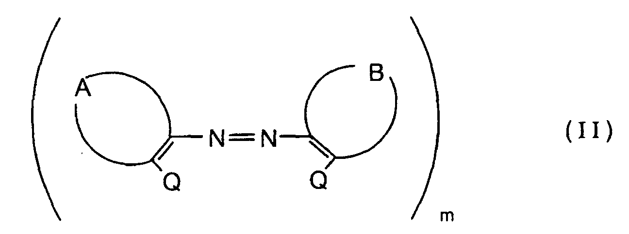 R1 and R2 are each independently a substituted or unsubstituted alkyl group having 1 - 6 carbon atoms or a substituted or unsubstituted alkenyl group having 1 - 6 carbon atoms;Z1 and Z2 are each independently a 5- or 6-membered heterocycle or an atomic group capable of forming a condensed ring containing a 5- or 6-membered heterocycle;Y1 is a hydrogen atom, a halogen atom or an alkyl group having 1 or 2 carbon atoms;X is a monovalent anion;A and B are each independently an atomic group which, together with the two carbon atoms to which they each are bound, forms an aromatic ring or a condensed ring that may have the same or different substituents;Q is a group having active hydrogen;m is a number of 1 or 2.
Applications Claiming Priority (5)
| Application Number | Priority Date | Filing Date | Title |
|---|---|---|---|
| JP2000276660 | 2000-09-12 | ||
| JP2000276661A JP2002092963A (en) | 2000-09-12 | 2000-09-12 | Optical recording medium |
| JP2000276661 | 2000-09-12 | ||
| JP2000276660A JP3818629B2 (en) | 2000-09-12 | 2000-09-12 | Optical recording medium |
| PCT/JP2001/007867 WO2002023544A1 (en) | 2000-09-12 | 2001-09-11 | Optical recording medium |
Publications (2)
| Publication Number | Publication Date |
|---|---|
| EP1326243A1 true EP1326243A1 (en) | 2003-07-09 |
| EP1326243A4 EP1326243A4 (en) | 2008-04-23 |
Family
ID=26599765
Family Applications (1)
| Application Number | Title | Priority Date | Filing Date |
|---|---|---|---|
| EP01963578A Withdrawn EP1326243A4 (en) | 2000-09-12 | 2001-09-11 | Optical recording medium |
Country Status (4)
| Country | Link |
|---|---|
| US (6) | US20020075793A1 (en) |
| EP (1) | EP1326243A4 (en) |
| TW (1) | TW564416B (en) |
| WO (1) | WO2002023544A1 (en) |
Cited By (1)
| Publication number | Priority date | Publication date | Assignee | Title |
|---|---|---|---|---|
| EP1757661A1 (en) * | 2005-08-23 | 2007-02-28 | TDK Corporation | Dye material, optical recording medium using the same, and method of manufacturing the optical recording medium |
Families Citing this family (11)
| Publication number | Priority date | Publication date | Assignee | Title |
|---|---|---|---|---|
| US7239602B2 (en) * | 1998-08-27 | 2007-07-03 | Ricoh Company, Ltd. | Optical information recording medium with a partition wall between an information tracks groove and a preformat pit encoding information therefor |
| MXPA05010025A (en) * | 2003-03-24 | 2005-10-26 | Koninkl Philips Electronics Nv | Optical disc having focus offset area. |
| US7369483B2 (en) * | 2004-01-21 | 2008-05-06 | Microcontinuum, Inc. | Pre-formatted linear optical data storage medium |
| USRE44893E1 (en) | 2004-03-26 | 2014-05-13 | Hanwha Azdel, Inc. | Fiber reinforced thermoplastic sheets with surface coverings |
| US7682697B2 (en) * | 2004-03-26 | 2010-03-23 | Azdel, Inc. | Fiber reinforced thermoplastic sheets with surface coverings |
| JP2007323719A (en) * | 2006-05-31 | 2007-12-13 | Toshiba Corp | Optical disc, information recording method, information reproducing method |
| US8178818B2 (en) * | 2008-03-31 | 2012-05-15 | Electro Scientific Industries, Inc. | Photonic milling using dynamic beam arrays |
| US7982160B2 (en) | 2008-03-31 | 2011-07-19 | Electro Scientific Industries, Inc. | Photonic clock stabilized laser comb processing |
| CN102171759B (en) * | 2008-09-12 | 2017-01-18 | 布莱阿姆青年大学 | Data storage media containing carbon and metal layers |
| EP2334841A4 (en) * | 2008-09-12 | 2013-07-17 | Univ Brigham Young | FILMS CONTAINING INFUSED OXYGENIC GAS AND METHODS OF PREPARATION THEREOF |
| EP2273498A1 (en) * | 2009-06-24 | 2011-01-12 | Thomson Licensing | Compatible optical recording medium |
Family Cites Families (12)
| Publication number | Priority date | Publication date | Assignee | Title |
|---|---|---|---|---|
| US5144552A (en) * | 1986-07-25 | 1992-09-01 | Ricoh Company, Ltd. | Optical information storage medium having grooves and pits with specific depths, respectively |
| JP2723986B2 (en) * | 1989-08-02 | 1998-03-09 | 株式会社日立製作所 | Manufacturing method of optical disc master |
| US5344683A (en) * | 1989-10-27 | 1994-09-06 | Ricoh Company, Ltd. | Optical information recording medium with phase grooves in land portions of information recording areas |
| CA2110233C (en) * | 1992-12-02 | 1999-01-12 | Mitsui Toatsu Chemicals, Incorporated | Optical information recording medium and composition for optical information recording film |
| US5602824A (en) * | 1994-08-12 | 1997-02-11 | Nikon Corporation | Optical disk capable of recording information on both land and groove tracks |
| JPH08221804A (en) * | 1995-02-16 | 1996-08-30 | Sony Corp | optical disk |
| JP3917207B2 (en) * | 1996-01-12 | 2007-05-23 | パイオニア株式会社 | Pre-information recording method and apparatus, information recording method and apparatus, and information recording medium |
| JPH09306030A (en) * | 1996-05-10 | 1997-11-28 | Sony Corp | recoding media |
| KR100433238B1 (en) | 1998-04-04 | 2004-09-16 | 엘지전자 주식회사 | Optical Disc and Method and Apparatus of Fabricating Master Disc for the Same |
| JP3520203B2 (en) | 1998-07-23 | 2004-04-19 | 太陽誘電株式会社 | Optical information media |
| TW493172B (en) * | 1999-02-23 | 2002-07-01 | Taiyo Yuden Kk | Optical information medium and recording method therefor |
| DE60034734T2 (en) * | 1999-04-08 | 2008-01-17 | Pioneer Corporation | Optical record carrier |
-
2001
- 2001-09-11 EP EP01963578A patent/EP1326243A4/en not_active Withdrawn
- 2001-09-11 WO PCT/JP2001/007867 patent/WO2002023544A1/en not_active Ceased
- 2001-09-11 TW TW090122514A patent/TW564416B/en not_active IP Right Cessation
- 2001-09-12 US US09/950,072 patent/US20020075793A1/en not_active Abandoned
-
2004
- 2004-04-26 US US10/831,363 patent/US20050063291A1/en not_active Abandoned
-
2006
- 2006-09-18 US US11/522,310 patent/US20070008869A1/en not_active Abandoned
-
2007
- 2007-05-07 US US11/745,060 patent/US20070206484A1/en not_active Abandoned
-
2008
- 2008-03-28 US US12/058,069 patent/US20080192620A1/en not_active Abandoned
-
2009
- 2009-01-05 US US12/348,495 patent/US20090116372A1/en not_active Abandoned
Cited By (1)
| Publication number | Priority date | Publication date | Assignee | Title |
|---|---|---|---|---|
| EP1757661A1 (en) * | 2005-08-23 | 2007-02-28 | TDK Corporation | Dye material, optical recording medium using the same, and method of manufacturing the optical recording medium |
Also Published As
| Publication number | Publication date |
|---|---|
| US20050063291A1 (en) | 2005-03-24 |
| US20090116372A1 (en) | 2009-05-07 |
| US20020075793A1 (en) | 2002-06-20 |
| EP1326243A4 (en) | 2008-04-23 |
| WO2002023544A1 (en) | 2002-03-21 |
| US20070206484A1 (en) | 2007-09-06 |
| US20080192620A1 (en) | 2008-08-14 |
| TW564416B (en) | 2003-12-01 |
| US20070008869A1 (en) | 2007-01-11 |
Similar Documents
| Publication | Publication Date | Title |
|---|---|---|
| US20090116372A1 (en) | Optical recording medium | |
| US6580678B2 (en) | Rewritable compact disk and manufacturing method thereof | |
| EP1587092B1 (en) | Write-once information recording medium and dyes therefor | |
| US7914711B2 (en) | Use of mother stamper for optical disk molding | |
| JP2002036726A (en) | Optical recording medium and method for reproducing record of the same | |
| TW201216279A (en) | Storage medium, reproducing method, and recording method | |
| JP3818629B2 (en) | Optical recording medium | |
| US7125594B2 (en) | Write-once optical recording medium | |
| JP2002092963A (en) | Optical recording medium | |
| JP3600177B2 (en) | Optical recording medium and manufacturing method thereof | |
| JPH07122935B2 (en) | Optical information recording medium and manufacturing method thereof | |
| US20030113671A1 (en) | Manufacturing method for optical disc master | |
| JP3883277B2 (en) | Optical recording medium and manufacturing method thereof | |
| US20030161987A1 (en) | Optical recording medium | |
| JP2003217171A (en) | Optical recording medium and manufacturing method thereof | |
| JPH05198012A (en) | Optical recording medium, substrate for optical recording medium, and stamper | |
| JP5108343B2 (en) | Optical recording medium | |
| JP2003077185A (en) | Optical information recording medium | |
| JPH10166732A (en) | Optical recording medium | |
| JP2002237101A (en) | Optical recording medium | |
| JP2007035181A (en) | Optical disk cartridge housing body | |
| JP2006031857A (en) | Optical recording medium | |
| JP2000048406A (en) | Optical recording medium | |
| JPH04274036A (en) | Optical recording medium disk | |
| JP2002216364A (en) | optical disk |
Legal Events
| Date | Code | Title | Description |
|---|---|---|---|
| PUAI | Public reference made under article 153(3) epc to a published international application that has entered the european phase |
Free format text: ORIGINAL CODE: 0009012 |
|
| 17P | Request for examination filed |
Effective date: 20030325 |
|
| AK | Designated contracting states |
Designated state(s): DE FR GB NL |
|
| AX | Request for extension of the european patent |
Extension state: AL LT LV MK RO SI |
|
| A4 | Supplementary search report drawn up and despatched |
Effective date: 20080320 |
|
| 17Q | First examination report despatched |
Effective date: 20080704 |
|
| STAA | Information on the status of an ep patent application or granted ep patent |
Free format text: STATUS: THE APPLICATION IS DEEMED TO BE WITHDRAWN |
|
| 18D | Application deemed to be withdrawn |
Effective date: 20110401 |