EP1326107A2 - Athermal optical coupler - Google Patents
Athermal optical coupler Download PDFInfo
- Publication number
- EP1326107A2 EP1326107A2 EP02023884A EP02023884A EP1326107A2 EP 1326107 A2 EP1326107 A2 EP 1326107A2 EP 02023884 A EP02023884 A EP 02023884A EP 02023884 A EP02023884 A EP 02023884A EP 1326107 A2 EP1326107 A2 EP 1326107A2
- Authority
- EP
- European Patent Office
- Prior art keywords
- waveguide
- expansion
- expansion element
- frame means
- engaging
- Prior art date
- Legal status (The legal status is an assumption and is not a legal conclusion. Google has not performed a legal analysis and makes no representation as to the accuracy of the status listed.)
- Withdrawn
Links
Images


Classifications
-
- G—PHYSICS
- G02—OPTICS
- G02B—OPTICAL ELEMENTS, SYSTEMS OR APPARATUS
- G02B6/00—Light guides; Structural details of arrangements comprising light guides and other optical elements, e.g. couplings
- G02B6/10—Light guides; Structural details of arrangements comprising light guides and other optical elements, e.g. couplings of the optical waveguide type
- G02B6/12—Light guides; Structural details of arrangements comprising light guides and other optical elements, e.g. couplings of the optical waveguide type of the integrated circuit kind
- G02B6/12007—Light guides; Structural details of arrangements comprising light guides and other optical elements, e.g. couplings of the optical waveguide type of the integrated circuit kind forming wavelength selective elements, e.g. multiplexer, demultiplexer
- G02B6/12009—Light guides; Structural details of arrangements comprising light guides and other optical elements, e.g. couplings of the optical waveguide type of the integrated circuit kind forming wavelength selective elements, e.g. multiplexer, demultiplexer comprising arrayed waveguide grating [AWG] devices, i.e. with a phased array of waveguides
- G02B6/12016—Light guides; Structural details of arrangements comprising light guides and other optical elements, e.g. couplings of the optical waveguide type of the integrated circuit kind forming wavelength selective elements, e.g. multiplexer, demultiplexer comprising arrayed waveguide grating [AWG] devices, i.e. with a phased array of waveguides characterised by the input or output waveguides, e.g. tapered waveguide ends, coupled together pairs of output waveguides
-
- G—PHYSICS
- G02—OPTICS
- G02B—OPTICAL ELEMENTS, SYSTEMS OR APPARATUS
- G02B6/00—Light guides; Structural details of arrangements comprising light guides and other optical elements, e.g. couplings
- G02B6/10—Light guides; Structural details of arrangements comprising light guides and other optical elements, e.g. couplings of the optical waveguide type
- G02B6/12—Light guides; Structural details of arrangements comprising light guides and other optical elements, e.g. couplings of the optical waveguide type of the integrated circuit kind
- G02B6/12007—Light guides; Structural details of arrangements comprising light guides and other optical elements, e.g. couplings of the optical waveguide type of the integrated circuit kind forming wavelength selective elements, e.g. multiplexer, demultiplexer
- G02B6/12009—Light guides; Structural details of arrangements comprising light guides and other optical elements, e.g. couplings of the optical waveguide type of the integrated circuit kind forming wavelength selective elements, e.g. multiplexer, demultiplexer comprising arrayed waveguide grating [AWG] devices, i.e. with a phased array of waveguides
- G02B6/12026—Light guides; Structural details of arrangements comprising light guides and other optical elements, e.g. couplings of the optical waveguide type of the integrated circuit kind forming wavelength selective elements, e.g. multiplexer, demultiplexer comprising arrayed waveguide grating [AWG] devices, i.e. with a phased array of waveguides characterised by means for reducing the temperature dependence
- G02B6/1203—Light guides; Structural details of arrangements comprising light guides and other optical elements, e.g. couplings of the optical waveguide type of the integrated circuit kind forming wavelength selective elements, e.g. multiplexer, demultiplexer comprising arrayed waveguide grating [AWG] devices, i.e. with a phased array of waveguides characterised by means for reducing the temperature dependence using mounting means, e.g. by using a combination of materials having different thermal expansion coefficients
-
- G—PHYSICS
- G02—OPTICS
- G02B—OPTICAL ELEMENTS, SYSTEMS OR APPARATUS
- G02B6/00—Light guides; Structural details of arrangements comprising light guides and other optical elements, e.g. couplings
- G02B6/24—Coupling light guides
- G02B6/26—Optical coupling means
-
- G—PHYSICS
- G02—OPTICS
- G02B—OPTICAL ELEMENTS, SYSTEMS OR APPARATUS
- G02B6/00—Light guides; Structural details of arrangements comprising light guides and other optical elements, e.g. couplings
- G02B6/24—Coupling light guides
- G02B6/26—Optical coupling means
- G02B6/30—Optical coupling means for use between fibre and thin-film device
-
- G—PHYSICS
- G02—OPTICS
- G02B—OPTICAL ELEMENTS, SYSTEMS OR APPARATUS
- G02B6/00—Light guides; Structural details of arrangements comprising light guides and other optical elements, e.g. couplings
- G02B6/24—Coupling light guides
- G02B6/26—Optical coupling means
- G02B6/32—Optical coupling means having lens focusing means positioned between opposed fibre ends
-
- G—PHYSICS
- G02—OPTICS
- G02B—OPTICAL ELEMENTS, SYSTEMS OR APPARATUS
- G02B6/00—Light guides; Structural details of arrangements comprising light guides and other optical elements, e.g. couplings
- G02B6/24—Coupling light guides
- G02B6/36—Mechanical coupling means
Definitions
- the present invention relates to optical coupling between waveguides, and in particular to an optical coupler for coupling light between a slab waveguide and an optical fiber which is able to compensate for changes in temperature.
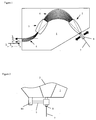
- a conventional slab-launched array waveguide grating illustrated in Figure 1, is integrated into a substrate 1, and includes a first slab waveguide 2 arid a second slab waveguide 3, which are optically connected by an array of discrete waveguides 4.
- a plurality of discrete input/output waveguides 6 enable signals to be launched into or retrieved from the second slab waveguide 3.
- each of the waveguides 4 has a different length designed so that when a wavelength division multiplexed (WDM) signal is launched into either of the slab waveguides 2 and 3, the signal gets split into sub-beams, which travel along the different discrete waveguides 4 and interfere in the other slab waveguide, thereby creating sub-beams with discrete wavelengths.
- WDM wavelength division multiplexed
- the discrete wavelengths can be output via the discrete input/output waveguides 6.
- this process is completely reciprocal and reversible, i.e. discrete wavelengths launched into either slab waveguide get combined into a single WDM signal for output the other slab waveguide.
- the ferrule 8 would be fixed directly to the edge of the substrate 1 in the position providing the highest possible optical coupling therebetween at an optimum set temperature.
- changes in temperature encountered in use cause changes in the properties of the waveguides, e.g. the index of refraction, which results in shifts in the center wavelengths of the channels in the output signal.
- various attempts have been made to compensate for optical coupling losses caused by changes in temperature by mounting one of the waveguides 7 on an expansion arm 9 that has a coefficient of thermal expansion (CTE) different than the support 10 fixed to the other waveguide 2.
- CTE coefficient of thermal expansion
- An object of the present invention is to overcome the shortcomings of the prior art by providing a thermally compensated optical coupler, which is much more stable than the prior art over repeated usage.
- the present invention relates to a device for optically coupling a first waveguide to a second waveguide for transmitting a optical signal defined by a center wavelength therebetween, comprising:
- Another aspect of the present invention relates to a device for optically coupling a first waveguide to a second waveguide via a lens for transmitting an optical signal defined by a center wavelength therebetween, comprising:
- Yet another feature of the present invention relates to a device for optically coupling a first waveguide to a second waveguide for transmitting a optical signal defined by a center wavelength therebetween, comprising:
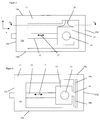
- An athermal coupler which is illustrated in Figure 3, includes a generally rectangular frame 11, an expansion element 12, and a waveguide block 13.
- the frame 11 has upper and lower surfaces 15a and 15b, respectively, two sides 15c and 15d, and front and rear faces 15e and 15f, respectively.
- the upper and lower surfaces 15a and 15b form upper and lower frame members 15a and 15b.
- One end of the expansion element 12 is fixed to one side 15a of the frame 11, while the other end is fixed to the waveguide block 13.
- the waveguide block 13 includes a cavity 14 extending therethrough which is adapted to receive a waveguide, e.g. an optical fiber ferrule, or some other element with optical power used to couple light between the waveguides, e.g.
- a GRIN lens See Figures 6 to 8 for examples of elements supported in the waveguide block 13.
- the shape of the waveguide block is unimportant to the invention, and is simply a way to fix a waveguide (or a lens, etc.) onto the end of the expansion element 12, whereby the waveguide directs light in a transmission direction into the other waveguide.
- the waveguide block 13 could also be integral with the frame 11, if desired.
- the waveguide block 13 is suspended from the upper frame member 15a by a flexible or resilient arm 16, which extends from the upper frame member 15a to the top of the waveguide block 13.
- the flexible arm 16 enables the expansion element 12 to move the waveguide block 13 laterally in an expansion/contraction direction indicated by arrow 17, i.e.
- the flexible arm 16 can be a single rod with a constant or varying cross-section, or a rectangular, planar, web-like member extending in the direction from the front face 15e of the frame 11 to the rear face 15f. In this embodiment the path taken by the waveguide block 13 is somewhat arcuate.
- the frame 11 and the waveguide block 13 are integrally manufactured from the same material with a very low CTE, e.g. Invar®, Kovar®, while the expansion element 12 is manufactured from a material with a higher CTE, e.g. an aluminum alloy. Invar® and Kovar® have a CTE less than 10 x 10 -6 m/m°C for temperatures ranging from 25°C to 200°C.
- a second embodiment of the present invention is similar to the aforementioned embodiment except that the flexible arm 16 is replaced with a pair of flexible arms 18a and 18b, joined to the side of the waveguide block 13 opposite the expansion element 12 at joint 19.
- the waveguide block 13 is completely restrained from moving in the y direction, i.e. perpendicular to the expansion direction 17, by an arm on either side thereof.
- the arms 18a and 18b are preferably planar, web-like members joined to the upper frame member 15a and the lower frame members 15b, respectively, and extending from the front face 15e of the frame 11 to the rear face 15f.
- the frame 11, the arms 18a and 18b, and the waveguide block 13 can be constructed from a single block of low CTE material.
- the manufacturing process starts by milling out the voided areas from the front face 15e through to the rear face 15f, thereby making only the front and rear faces 15e and 15f open, while leaving the remaining sides substantially closed.
- a hole can be provided through the side wall 15c for receiving the expansion element 12.
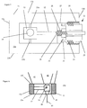
- Figure 5 illustrates a third embodiment of the present invention, in which a flexible arm 21a extends from the upper frame member 15a to the top of the waveguide block 13, while a flexible arm 21b extends from the lower frame member 15b to the bottom of the waveguide block 13.
- the arms 21a and 21b can be a single rod or a planar web-like member extending in the direction from the front face 15e to the rear face 15f of the frame 11.
- the flexible arms 21a and 21b restrain the waveguide block from moving in the y direction, i.e. perpendicular to the expansion direction 17.
- the moveable clamp 22 includes a first sleeve 23 with threads 24 for engaging threads 26 in the frame 11.
- the moveable clamp 22 also includes a second sleeve 27, slideable in the frame 11, with threads 28 for engaging threads 29 on the expansion element 12.
- the first sleeve 23 also includes an annular ring 31 for abutting a shoulder 32 formed in the second sleeve 27. Accordingly, rotation of the first sleeve 23 moves the entire moveable clamp 22 into the frame 11, while rotation of the expansion element 12 in the opposite direction withdraws only the expansion element 12, thereby adjusting the effective length (L) thereof, i.e. the distance from the waveguide block 13 to a point at which the threads 28 and 29 last mate.
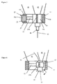
- Figure 6 illustrates a device of the present invention with a frame 11 mounted on the edge of a substrate 41 for aligning a slab waveguide 42 with a fiber waveguide 43, which has one end encased in a ferrule 44.
- the expansion element 12 expands and contracts, which moves the fiber 43 relative to the slab waveguide 42, thereby at least partially compensating for the potential change in center wavelength that would have resulted from the initial change in ambient temperature.
- the flexible arm 16 prevents the waveguide block 13 from wavering in the direction perpendicular to the expansion/contraction direction.
- a 1 ⁇ 2 -pitch lens 46 e.g. a GRIN lens
- the ferrule 44 with fiber 43 can be easily attached to the lens 46 during installation. Accordingly, installation is made easier by eliminating the need to mount the ferrule 44 or anything else in the waveguide block 13.
- the embodiment of Figure 7 includes arms 21a and 21b (only one of which is shown), and the moveable clamp 22 with first and second sleeves 23 and 27, respectively.
- Figure 8 illustrates an alternative embodiment of the present invention in which a 1 ⁇ 4 -pitch lens 51, e.g. a GRIN lens, is mounted in the waveguide block 13 with a reflective surface 52 positioned or coated on one end thereof.
- One end of the second waveguide 53 e.g. an optical fiber, can therefore be positioned on the same side of the lens 51 as the first waveguide 42, but still move with the lens 51.
- the waveguide 53 can be integrated into the substrate 41 with the other end thereof positioned adjacent the input/output waveguides of the AWG device. In this case, neither waveguide would actually move; however, the entry point of the signal into the lens 51 would change, thereby changing the exit point.
- the lens 51 would be considered the second waveguide, while the integrated waveguide 53 would be a third waveguide. It is also possible for the reflective surface 52 to be pivotable to enable additional tuning.
- the pivot position can be preset, actively set during use or passively adjusted by a pivoting expansion element. The passive process is fully described in United States Patent Publication No. 2001/0033715 published October 25, 2001 in the name of Vincent Delisle et al, which is incorporated herein by reference.
- FIG. 9 to 11 A vastly different approach to the present invention is illustrated in Figures 9 to 11.
- the front and rear faces 15e and 15f of the frame 11 were open, and the arms 16, 18 and 21 flexed about an axis parallel to the longitudinal axis of the waveguide 43, i.e. the transmission direction.
- the length of the arms are restricted by the height of the frame 11, i.e. from the upper member 15a to the lower member 15b. Due to a desire to keep the overall package small, the arms were also kept relatively small, which can lead to high stresses at specific locations.
- the upper and lower frame members 15a and 15b are open, while the front and rear faces 15e and 15f of the frame 11 are closed, except for the cavity 14.
- the waveguide block 13 is suspended by first and second arms 61 and 62, respectively, which are each joined to the front and rear surfaces 15e and 15f, and which extend from the upper frame member 15a to the lower frame member 15b.
- the arms 61 and 62 flex about an axis perpendicular to the longitudinal axis of the waveguide 43, i.e. perpendicular to the transmission direction. Accordingly, the size of the arms are limited by the width of the frame 11, i.e. from the front face 15e to the rear face 15f, not by the height of the frame 11, which can now be kept short.
- the arms 61 and 62 are joined to the waveguide block 13 by joints 63 and 64, respectively, which extend from the upper surface15a to the lower surface 15b.
- the arms 61 and 62 have broad mid-sections for reinforcement.
- a set screw 66 is provided for locking the expansion element in position.
- Other access holes 67 are provided for the insertion of an adhesive to further solidify the structure.
- the ferrule 44 is mounted in the waveguide block 13 for launching a signal into the slab waveguide 42 provided in the substrate 41.
- the manufacturing process for integrally constructing this embodiment is similar to that of the device of Figure 4, except the milling is done from the upper surface 15a to the lower surface 15b, leaving the front and rear faces 15e and 15f solid except for a hole drilled for the cavity 14. Again a hole is drilled through one of the sides 15c or 15d to receive the expansion element 12
- Figures 9 to 11 also illustrate an alternative embodiment of the moveable clamp 22 for adjusting the length of the expansion element 12.
- the positions of the first and second sleeves 23 and 27 are opposite to those in Figure 5.
- Figure 10 illustrates a retracted position, in which the first sleeve 23 has been threaded into the frame 11, and the effective length is X, as shown.
- Figure 11 illustrated an extended position, in which the first sleeve has been partially threaded out of the frame 11, while the expansion element 12 has been threaded back into position using the threads on the second sleeve 27.
- the effective length X + ⁇ of the expansion element 12 is therefore larger than before by approximately 4mm or 10%.
Landscapes
- Physics & Mathematics (AREA)
- General Physics & Mathematics (AREA)
- Optics & Photonics (AREA)
- Engineering & Computer Science (AREA)
- Microelectronics & Electronic Packaging (AREA)
- Optical Couplings Of Light Guides (AREA)
- Optical Integrated Circuits (AREA)
Abstract
Description
Claims (20)
- A device for optically coupling a first waveguide to a second waveguide for transmitting a optical signal defined by a center wavelength therebetween, comprising:frame means for mounting in a fixed position relative to said first waveguide;an expansion element, one end of which is connected to said frame means, for expanding or contracting in an expansion direction in response to an ambient temperature change, said expansion element having a coefficient of thermal expansion different than said frame means;a waveguide block pivotally connected to said frame means by arm means extending substantially perpendicularly to the expansion direction from opposite sides of said frame means, said waveguide block engaged with another end of said expansion element for supporting said second waveguide in a transmission direction relative to said first waveguide;whereby a shift in the center wavelength due to a change in ambient temperature is at least partially compensated for by movement of the second waveguide relative to the first waveguide resulting from the expansion or contraction of said expansion element.
- The device according to claim 1, wherein said arm means comprise first and second resilient arms extending between said waveguide block and said frame means.
- The device according to claim 2, wherein the first and second resilient arms extend from opposite sides of said waveguide block.
- The device according to claim 2, wherein the first and second resilient arms are planar, web-like arms.
- The device according to claim 4, wherein the first and second resilient arms are fixed to the frame means along axes parallel to the transmission direction.
- The device according to claim 4, wherein the first and second resilient arms are fixed to the frame means along an axis perpendicular to the transmissions direction.
- The device according to claim 6, wherein the first and second resilient arms are integral with the waveguide block and the frame means, and constructed from a material having a coefficient of thermal expansion less than 10 x 10-6 m/m°C for temperatures ranging from 25°C to 200°C.
- The device according to claim 1, wherein the first waveguide is a slab waveguide integrated into a substrate; and wherein said frame means is for mounting on the edge of the substrate adjacent the slab waveguide.
- The device according to claim 1, wherein the second waveguide includes a lens mounted in said waveguide block for optically coupling said second waveguide with said first waveguide.
- The device according to claim 1, wherein the first or the second waveguide includes a lens with a reflective surface on one end thereof mounted in said waveguide block for optically coupling said first waveguide to said second waveguide.
- The device according to claim 10, wherein said first waveguide is integrated in a substrate and optically coupled to another end of said lens; and wherein the second waveguide is also optically coupled to the other end of said lens.
- The device according to claim 11, wherein the second waveguide is a lens for optically coupling the first waveguide with a third waveguide integrated in the substrate.
- The device according to claim 1, wherein the expansion element has an adjustable effective length for presetting the amount of expansion or contraction in response to a given rise in temperature.
- The device according to claim 13, further comprising clamping means moveable along said expansion element for adjusting the effective length thereof, said clamping means including first engaging means for engaging said expansion element, and second engaging means for engaging said frame means.
- The device according to claim 14, wherein said expansion element and said frame means each include threads; wherein said first engaging means has threads for engaging the threads on said expansion element; and wherein said second engaging means has threads for engaging the threads on said frame means.
- A device for optically coupling a first waveguide to a second waveguide via a lens for transmitting an optical signal defined by a center wavelength therebetween, comprising:frame means for mounting in a fixed position relative to said first waveguide;an expansion element, one end of which is connected to said frame means, for expanding or contracting in an expansion direction in response to a temperature change, said expansion element having a coefficient of thermal expansion higher than said frame means;a waveguide block flexibly connected to said frame means and engaged with another end of said expansion element for supporting the lens relative to said first waveguide;whereby a shift in the center wavelength due to a change in ambient temperature is at least partially compensated for by movement of the lens relative to the first waveguide caused by the expansion or contraction of said expansion element.
- The device according to claim 16, wherein the lens has a reflective surface on one end thereof.
- A device for optically coupling a first waveguide to a second waveguide for transmitting a optical signal defined by a center wavelength therebetween, comprising:frame means for mounting in a fixed position relative to said first waveguide;an expansion element, one end of which is connected to said frame means, for expanding or contracting in an expansion direction in response to a temperature change, said expansion element having a coefficient of thermal expansion different than said frame means, said expansion element having an adjustable effective length for presetting the amount of expansion or contraction in response to a given rise in temperature;a waveguide block engaged with another end of said expansion element for supporting said second waveguide, or a lens optically coupled with said second waveguide, relative to said first waveguide;whereby a shift in the center wavelength due to a change in ambient temperature is at least partially compensated for by movement of the second waveguide or the lens relative to the first waveguide caused by the expansion or contraction of said expansion element.
- The device according to claim 18, further comprising clamping means moveable along said expansion element for adjusting the effective length thereof, said clamping means including first engaging means for engaging said expansion element, and second engaging means for engaging said frame means.
- The device according to claim 19, wherein said expansion element and said frame means each include threads; wherein said first engaging means has threads for engaging the threads on said expansion element; and wherein said second engaging means has threads for engaging the threads on said frame means.
Applications Claiming Priority (2)
| Application Number | Priority Date | Filing Date | Title |
|---|---|---|---|
| US34655302P | 2002-01-04 | 2002-01-04 | |
| US346553P | 2002-01-04 |
Publications (2)
| Publication Number | Publication Date |
|---|---|
| EP1326107A2 true EP1326107A2 (en) | 2003-07-09 |
| EP1326107A3 EP1326107A3 (en) | 2004-03-10 |
Family
ID=23359937
Family Applications (1)
| Application Number | Title | Priority Date | Filing Date |
|---|---|---|---|
| EP02023884A Withdrawn EP1326107A3 (en) | 2002-01-04 | 2002-10-24 | Athermal optical coupler |
Country Status (2)
| Country | Link |
|---|---|
| US (1) | US6865323B2 (en) |
| EP (1) | EP1326107A3 (en) |
Cited By (1)
| Publication number | Priority date | Publication date | Assignee | Title |
|---|---|---|---|---|
| DE102006025410A1 (en) * | 2006-05-31 | 2007-12-06 | Photeon Technologies Gmbh | Demultiplexer for e.g. optical data transmission, has coupler provided for coupling with input waveguides, where coupler is attached to waveguide array and has section whose cross section reduces towards waveguide array |
Families Citing this family (9)
| Publication number | Priority date | Publication date | Assignee | Title |
|---|---|---|---|---|
| US7149373B2 (en) * | 2004-02-02 | 2006-12-12 | Lucent Technologies Inc. | Active/passive monolithically integrated channel filtering polarization splitter |
| KR100763790B1 (en) * | 2005-01-07 | 2007-10-08 | (주)포인테크 | Temperature-independent optical waveguide grating and its manufacturing method |
| ATE521106T1 (en) * | 2006-04-25 | 2011-09-15 | Thruvision Systems Ltd | FEEDHORN ASSEMBLY AND PRODUCTION PROCESS THEREOF |
| US9239431B1 (en) * | 2011-11-29 | 2016-01-19 | Sandia Corporation | Athermalization of resonant optical devices via thermo-mechanical feedback |
| US9285538B2 (en) | 2012-10-23 | 2016-03-15 | Lumentum Operations Llc | Reducing temperature drift of an arrayed waveguide grating |
| WO2018229992A1 (en) * | 2017-06-16 | 2018-12-20 | 京セラ株式会社 | Optical connector module |
| CN110389406B (en) * | 2018-04-17 | 2020-10-27 | 华为技术有限公司 | Waveguide assembly, unequal-arm Mach-Zehnder interferometer and parameter determination method |
| JP7268180B2 (en) * | 2019-02-28 | 2023-05-02 | モレックス エルエルシー | A New and Improved Variable Bidirectional Thermal Compensator for Arrayed Waveguide Grating (AWG) Modules |
| WO2022024022A1 (en) * | 2020-07-31 | 2022-02-03 | Molex, Llc | New and improved variable dual-directional thermal compensator for arrayed waveguide grating (awg) modules |
Family Cites Families (18)
| Publication number | Priority date | Publication date | Assignee | Title |
|---|---|---|---|---|
| JPS62211979A (en) | 1986-03-12 | 1987-09-17 | Fujitsu Ltd | Coupling mechanism for semiconductor light-emitting device |
| JPS62237773A (en) | 1986-04-08 | 1987-10-17 | Nec Corp | Semiconductor light emitting device |
| US4864824A (en) | 1988-10-31 | 1989-09-12 | American Telephone And Telegraph Company, At&T Bell Laboratories | Thin film shape memory alloy and method for producing |
| JPH04116607A (en) | 1990-09-07 | 1992-04-17 | Nippon Telegr & Teleph Corp <Ntt> | Optical demultiplexer |
| DE4233489A1 (en) | 1992-10-05 | 1994-04-07 | Electronic Production Partners | Optical component |
| JP2843466B2 (en) | 1992-10-28 | 1999-01-06 | 日本電信電話株式会社 | Optical power splitter |
| EP0767921B1 (en) | 1994-06-28 | 1998-10-21 | Siemens Aktiengesellschaft | Device for spatially separating and/or bringing together optical wavelength channels |
| US5727099A (en) | 1996-07-19 | 1998-03-10 | Harman; Murray R. | Positioning system for controlling optical alignment of optical waveguides |
| TW355752B (en) | 1996-09-27 | 1999-04-11 | Siemens Ag | Optical coupling-device to couple the light between two waveguide-end-face |
| US5905824A (en) * | 1997-12-09 | 1999-05-18 | Delisle; Vincent | Temperature compensated insensitive optical multiplexor/demultiplexor |
| US5920663A (en) * | 1997-12-24 | 1999-07-06 | Lucent Technologies Inc. | Optical waveguide router with controlled transmission characteristics |
| GB9828584D0 (en) * | 1998-12-23 | 1999-02-17 | Qps Technology Inc | Method for nonlinear, post tunable, temperature compensation package of fiber bragg gratings |
| DE19934184A1 (en) * | 1999-07-21 | 2001-01-25 | Siemens Ag | Optical waveguide end-faces light coupling device e.g. for light-guide chip |
| DE19934183A1 (en) | 1999-07-21 | 2001-01-25 | Siemens Ag | Optical waveguide end-faces light coupling device e.g. for light-guide chip |
| DE19934179A1 (en) | 1999-07-21 | 2001-01-25 | Siemens Ag | Optical coupler for coupling light from first to second optical fibre ensures light coupling between 2 light conducting structures with high degree of security, reliability, cost-effective assembly |
| JP3434489B2 (en) * | 1999-09-24 | 2003-08-11 | 古河電気工業株式会社 | Array waveguide type diffraction grating |
| EP1148362A1 (en) * | 2000-04-20 | 2001-10-24 | JDS Uniphase Inc. | Arrayed waveguide grating having a reflective input coupling |
| US20030118308A1 (en) * | 2001-12-21 | 2003-06-26 | Terry Bricheno | Thermal compensation and alignment for optical devices |
-
2002
- 2002-10-24 EP EP02023884A patent/EP1326107A3/en not_active Withdrawn
- 2002-10-28 US US10/281,932 patent/US6865323B2/en not_active Expired - Lifetime
Cited By (1)
| Publication number | Priority date | Publication date | Assignee | Title |
|---|---|---|---|---|
| DE102006025410A1 (en) * | 2006-05-31 | 2007-12-06 | Photeon Technologies Gmbh | Demultiplexer for e.g. optical data transmission, has coupler provided for coupling with input waveguides, where coupler is attached to waveguide array and has section whose cross section reduces towards waveguide array |
Also Published As
| Publication number | Publication date |
|---|---|
| US20030128932A1 (en) | 2003-07-10 |
| EP1326107A3 (en) | 2004-03-10 |
| US6865323B2 (en) | 2005-03-08 |
Similar Documents
| Publication | Publication Date | Title |
|---|---|---|
| CA2320538C (en) | Arrayed waveguide grating and method for compensating optical transmitting center wavelength of light travelling through the same | |
| US6954566B2 (en) | Apparatus for thermal compensation of an arrayed waveguide grating | |
| EP2261709B1 (en) | Optical coupling device with optical waveguide coupled to optical device | |
| KR101409630B1 (en) | Eye piece and tunable chromatic dispersion compensator using the same | |
| US6775437B2 (en) | Temperature compensated optical waveguide structures | |
| RU2596176C2 (en) | Temperature-compensated grating units based on set of waveguides | |
| CA3117540A1 (en) | A demountable connection of an optical connector and an optical bench based connector using an alignment coupler | |
| US6865323B2 (en) | Athermal optical coupler | |
| JPH0943440A (en) | Integrated optical multiplexer / demultiplexer | |
| JP4688869B2 (en) | Low power AWG using athermal AWG and variable width grooves | |
| US6144789A (en) | Temperature compensating device for fiber gratings and a package therefor | |
| JP3677593B2 (en) | Optical demultiplexer and alignment method thereof | |
| US6778278B2 (en) | Temperature insensitive Mach-Zehnder interferometers and devices | |
| US6975793B2 (en) | Method and apparatus facilitating mechanical beam steering for optical integrated circuits | |
| JP3404031B2 (en) | Integrated optical multiplexer / demultiplexer | |
| CN107748421A (en) | A kind of base for being used to fix array waveguide grid chip | |
| US6925227B2 (en) | Optical device | |
| US20030219212A1 (en) | Variable alignment-type optical fiber block | |
| US6421479B1 (en) | Apparatus and method facilitating optical alignment of a bulk optical multiplexer/demultiplexer | |
| US6724960B1 (en) | Optical coupling device | |
| JP2006003651A (en) | Optical module and optical module manufacturing method | |
| JP3331180B2 (en) | Temperature-independent planar optical device | |
| JP2003232957A (en) | Optical module | |
| HK40010692A (en) | Thermally compensated arrayed waveguide grating assemblies | |
| JP2001324629A (en) | Arrayed waveguide grating |
Legal Events
| Date | Code | Title | Description |
|---|---|---|---|
| PUAI | Public reference made under article 153(3) epc to a published international application that has entered the european phase |
Free format text: ORIGINAL CODE: 0009012 |
|
| AK | Designated contracting states |
Designated state(s): AT BE BG CH CY CZ DE DK EE ES FI FR GB GR IE IT LI LU MC NL PT SE SK TR |
|
| AX | Request for extension of the european patent |
Extension state: AL LT LV MK RO SI |
|
| RIC1 | Information provided on ipc code assigned before grant |
Ipc: 7G 02B 6/34 B Ipc: 7G 02B 6/30 A |
|
| PUAL | Search report despatched |
Free format text: ORIGINAL CODE: 0009013 |
|
| AK | Designated contracting states |
Kind code of ref document: A3 Designated state(s): AT BE BG CH CY CZ DE DK EE ES FI FR GB GR IE IT LI LU MC NL PT SE SK TR |
|
| AX | Request for extension of the european patent |
Extension state: AL LT LV MK RO SI |
|
| AKX | Designation fees paid | ||
| REG | Reference to a national code |
Ref country code: DE Ref legal event code: 8566 |
|
| STAA | Information on the status of an ep patent application or granted ep patent |
Free format text: STATUS: THE APPLICATION IS DEEMED TO BE WITHDRAWN |
|
| 18D | Application deemed to be withdrawn |
Effective date: 20040911 |