EP1326080A2 - Voltage sensor for gas insulated electric apparatus - Google Patents
Voltage sensor for gas insulated electric apparatus Download PDFInfo
- Publication number
- EP1326080A2 EP1326080A2 EP02015077A EP02015077A EP1326080A2 EP 1326080 A2 EP1326080 A2 EP 1326080A2 EP 02015077 A EP02015077 A EP 02015077A EP 02015077 A EP02015077 A EP 02015077A EP 1326080 A2 EP1326080 A2 EP 1326080A2
- Authority
- EP
- European Patent Office
- Prior art keywords
- voltage
- gas insulated
- electrical apparatus
- transformer
- insulated electrical
- Prior art date
- Legal status (The legal status is an assumption and is not a legal conclusion. Google has not performed a legal analysis and makes no representation as to the accuracy of the status listed.)
- Granted
Links
Images



Classifications
-
- G—PHYSICS
- G01—MEASURING; TESTING
- G01R—MEASURING ELECTRIC VARIABLES; MEASURING MAGNETIC VARIABLES
- G01R15/00—Details of measuring arrangements of the types provided for in groups G01R17/00 - G01R29/00, G01R33/00 - G01R33/26 or G01R35/00
- G01R15/14—Adaptations providing voltage or current isolation, e.g. for high-voltage or high-current networks
- G01R15/16—Adaptations providing voltage or current isolation, e.g. for high-voltage or high-current networks using capacitive devices
- G01R15/165—Adaptations providing voltage or current isolation, e.g. for high-voltage or high-current networks using capacitive devices measuring electrostatic potential, e.g. with electrostatic voltmeters or electrometers, when the design of the sensor is essential
-
- H—ELECTRICITY
- H02—GENERATION; CONVERSION OR DISTRIBUTION OF ELECTRIC POWER
- H02B—BOARDS, SUBSTATIONS OR SWITCHING ARRANGEMENTS FOR THE SUPPLY OR DISTRIBUTION OF ELECTRIC POWER
- H02B13/00—Arrangement of switchgear in which switches are enclosed in, or structurally associated with, a casing, e.g. cubicle
- H02B13/02—Arrangement of switchgear in which switches are enclosed in, or structurally associated with, a casing, e.g. cubicle with metal casing
- H02B13/035—Gas-insulated switchgear
- H02B13/0356—Mounting of monitoring devices, e.g. current transformers
Definitions
- This invention relates to a transformer for a gas insulated electric apparatus and, in particular, to a transformer for a gas insulated electric apparatus for a gas insulated switching device used in the power system transformation field.
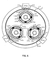
- Fig. 5 is a schematic diagram showing a voltage detecting device of a conventional three-phase-batch type gas insulated switching device as disclosed, for example, in Japanese Patent Application Laid-open No. Hei 2-115770.
- FIG. 5 three-phase high-voltage conductors 3a through 3c are arranged in a regular triangle in an annular grounding container 1 filled with an insulation arc-extinguishing gas, such as SF 6 gas.
- an insulation arc-extinguishing gas such as SF 6 gas.
- a disc-like partition mounting plate 17 consisting of a metal material, and bolts (not shown) are inserted into the peripheral portions of the high-voltage conductors 3a through 3c for fastening and fixation.
- This partition mounting plate 17 has coaxial through-holes 18a through 18c having a diameter which sufficiently allows insulation if the high-voltage conductors 3a through 3c are inserted, and single-phase spacers 19a through 19c made of insulating materials are respectively mounted to the through-holes 18a through 18c, supporting the high-voltage conductors 3a through 3c.
- cylindrical grounding shields 16a through 16c situated coaxially with the through-holes 18a through 18c of the partition mounting plate 17 and mitigating the electric field of the mounting flange portions of the single-phase spacers 19a through 19c are fixed to the partition mounting plate 17 by fastening screws common to the single-phase spacers 19a through 19c.
- cylindrical floating electrodes 15a through 15c are provided in the outer periphery of the high-voltage conductors 3a through 3c and inside the grounding shields 16a through 16c so as to be coaxial therewith, the floating electrodes 15a through 15c being secured to the respective grounding shields 16a through 16c through the intermediation of insulators 20.
- the respective floating electrodes 15a through 15c are connected to transformer portions 24a through 24c arranged outside the annular grounding container 1 and containing auxiliary capacitors through the intermediation of conductors 23 extending through insulation sealing terminals 21 on the annular grounding container 1 respectively mounted at the closest position and through hole portions 22a through 22c provided in the grounding shields 16a through 16c.
- the floating electrodes 15a through 15c are arranged at the centers of the grounding shields 16a through 16c with respect to the axial direction thereof, and the grounding shield length 1 x is substantially not less than twice the length 1 z of the floating electrodes 15a through 15c.
- the grounding shields 16a through 16c are provided coaxially with the floating electrodes 15a through 15c, so that it is difficult to reduce the inter-phase distance of the high-voltage conductors 3a through 3c, thus making it difficult to achieve a reduction in the size of the three-phase-batch type gas insulated switching device. Further, the provision of the grounding shields 16a through 16c leads to an increase in the cost of the three-phase-batch type gas insulated switching device.
- This invention has been made with a view to solving the above problems in the prior art. It is an object of this invention to provide a high-accuracy transformer for a gas insulated electrical apparatus which needs no grounding field and which has a simple structure.
- a transformer for a gas insulated electrical apparatus applicable to a gas insulated electrical apparatus in which a high-voltage conductor is arranged in an annular grounding container in which an insulation arc-extinguishing gas is sealed.
- the transformer comprises a capacitor type voltage divider having a floating electrode at a position opposed to a high-voltage conductor through an insulation sealing terminal mounted to a flange of a branch pipe provided on an inner surface of the annular grounding container.
- the transformer a converting portion which is connected in parallel to the ohm resistor for voltage division, which has an input impedance sufficiently larger than the resistance value of the ohm resistor for voltage division, and which converts the detection voltage of the high-voltage conductor to a voltage value that allows processing on the secondary side.
- Fig. 1 is a sectional view of a gas insulated electrical apparatus provided with a transformer for a gas insulated electrical apparatus according to Embodiment 1 of the present invention
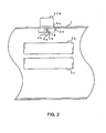
- Fig. 2 is a sectional view taken along the line A-A of Fig. 1.
- the components which are the same as or equivalent to those of Fig. 5 are indicated by the same reference numerals, and a description of such components will be omitted.
- high-voltage conductors 3a through 3c are accommodated in the annular grounding container 1, which is a pressure container filled with an insulation arc-extinguishing gas, such as SF 6 gas.
- Flange-shaped branch pipes 2a through 2c are mounted to the annular grounding container 1 so as to be opposed to the high-voltage conductors 3a through 3c, and voltage dividing portions 4a through 4c are fixed by the flange-shaped branch pipes 2a through 2c.
- the voltage dividing portions 4a through 4c are capacitor type voltage dividers composed of floating electrodes 5a through 5c consisting of disc-shaped flat antennas 6a through 6c and support conductors 7a through 7c, central conductors 9a through 9c, and insulation sealing terminals 8a through 8c consisting of flange-shaped cast insulators 10a through 10c.
- the support conductors 7a through 7c are connected to the flange-shaped cast insulators 10a through 10c so as to be perpendicular thereto by the central conductors 9a through 9c, and the floating electrodes 5a through 5c are insulated from the annular grounding container 1.
- the annular grounding container 1 is kept hermetic by the flange-shaped branch pipes 2a through 2c and the flange-shaped cast insulators 10a through 10c.
- one ends of ohm resistors for voltage division 11a through 11c are connected to the central conductors 9a through 9c, and the other ends of the ohm resistors for voltage division 11a through 11c are connected to grounding cases 12a through 12c which are at the same potential as the annular grounding container 1.
- temperature compensation resistor units 27a through 27c inside the voltage divider, it is possible to compensate for the temperature characteristic error in the floating capacitance between the high-voltage conductors 3a through 3c and the floating electrodes 5a through 5c, making it possible to obtain a transformer for a gas insulated electrical apparatus equipped with a more stable and highly accurate voltage divider.
- the converting portions 26a through 26c with an integration processing function and a function by which they convert electric analog signals into optical digital signals, it is possible to convert the detection voltage of the high-voltage conductors 3a through 3c to a voltage value that allows processing on the secondary side, making it possible to effect optical digital transmission of the secondary output voltage generated between the ohm resistors for voltage division 11a through 11c without being influenced by external noises.
- Fig. 3 is a sectional view showing a transformer portion of a gas insulated electrical apparatus according to Embodiment 2 of this invention.
- This embodiment differs from the above-described Embodiment 1 in that the floating electrodes 5a through 5c are formed by elliptic antennas 13a through 13c elongated in the axial direction of the high-voltage conductors 3a through 3c.
- Embodiment 2 constructed as described above, the influence of the electrostatic field due to the other-phase conductor voltage is diminished, as in Embodiment 1, making it possible to obtain a transformer for a gas insulated electrical apparatus equipped with a voltage divider which is stable and of high accuracy and in which the secondary output voltage is sufficiently high.
- Fig. 4 is a sectional view showing a transformer portion of a gas insulated electrical apparatus according to Embodiment 3 of this invention.
- This embodiment differs from the above-described Embodiments 1 and 2 in that the floating electrodes 5a through 5c are formed by spherical antennas 14a through 14c.
- the antenna portions exhibit no directivity, and there is no influence of assembly errors, etc., making it possible to obtain a transformer for a gas insulated electrical apparatus equipped with a voltage divider of a still higher accuracy.
- the present invention it is possible to obtain a stable and highly accurate voltage divider free from the influence of assembly errors, etc., so that it is possible to reduce the inter-phase distance of the high-voltage conductor without adopting a structure in which a grounding shield is provided.
- a grounding shield it is possible to achieve a reduction in the size of the gas insulated switching device, and there is no need to provide a grounding shield, thereby achieving a reduction in cost.
- the antenna portion exhibits no directivity, making it possible to diminish the influence of assembly errors, etc.
Landscapes
- Physics & Mathematics (AREA)
- General Physics & Mathematics (AREA)
- Transformers For Measuring Instruments (AREA)
- Measuring Instrument Details And Bridges, And Automatic Balancing Devices (AREA)
- Gas-Insulated Switchgears (AREA)
- Testing Relating To Insulation (AREA)
Abstract
Description
Claims (6)
- A transformer for a gas insulated electrical apparatus applicable to a gas insulated electrical apparatus in which a high-voltage conductor(3a,3b,3c) is arranged in an annular grounding container(1) in which an insulation arc-extinguishing gas is sealed, comprising:a capacitor type voltage divider (4a, 4b, 4c) having a floating electrode(5a,5b,5c) at a position opposed to a high-voltage conductor(3a,3b,3c) through an insulation sealing terminal(21) mounted to a flange of a branch pipe(2a,2b,2c) provided on an inner surface of the annular grounding container(1);an ohm resistor for voltage division(11a,11b,11c) which is mounted on an outer peripheral surface of the annular grounding container(1), one end of which is grounded and the other end of which is connected to the floating electrode (5a, 5b, 5c) through the capacitor type voltage divider(4a,4b,4c), and which has an impedance which is sufficiently smaller than the impedance between the floating electrode(5a,5b,5c) and the annular grounding container(1); anda converting portion(26a,26b,26c) which is connected in parallel to the ohm resistor for voltage division(11a,11b,11c), which has an input impedance sufficiently larger than the resistance value of the ohm resistor for voltage division(11a,11b,11c), and which converts the detection voltage of the high-voltage conductor(3a,3b,3c) to a voltage value that allows processing on the secondary side.
- A transformer for a gas insulated electrical apparatus according to Claim 1, wherein the floating electrode (5a,5b,5c) is formed as a disc having a diameter not larger than the diameter of the opposing high-voltage conductor(3a,3b,3c).
- A transformer for a gas insulated electrical apparatus according to Claim 1, wherein the floating electrode(5a,5b,5c) is formed as an elliptic plate having a shorter axis(7a,7b,7c) not longer than the diameter of the opposing high-voltage conductor(3a,3b,3c) and elongated in the axial direction of the high-voltage conductor (3a,3b,3c).
- A transformer for a gas insulated electrical apparatus according to Claim 1, wherein the floating electrode (5a,5b,5c) is formed in a spherical configuration having a diameter not larger than the diameter of the opposing high-voltage conductor (3a, 3b, 3c).
- A transformer for a gas insulated electrical apparatus according to any one of the preceding claims, wherein the converting portion(26a,26b,26c) is provided inside the transformer(25a,25b, 25c).
- A transformer for a gas insulated electrical apparatus according to any one of the preceding claims, further comprising a temperature compensation resistor unit for compensating for the temperature characteristic error in the floating capacitance between the high-voltage conductor(3a,3b,3c) and the floating electrode (5a,5b,5c).
Applications Claiming Priority (2)
| Application Number | Priority Date | Filing Date | Title |
|---|---|---|---|
| JP2002000462A JP4080749B2 (en) | 2002-01-07 | 2002-01-07 | Gas insulated electrical equipment transformer |
| JP2002000462 | 2002-01-07 |
Publications (3)
| Publication Number | Publication Date |
|---|---|
| EP1326080A2 true EP1326080A2 (en) | 2003-07-09 |
| EP1326080A3 EP1326080A3 (en) | 2004-01-28 |
| EP1326080B1 EP1326080B1 (en) | 2005-09-21 |
Family
ID=19190495
Family Applications (1)
| Application Number | Title | Priority Date | Filing Date |
|---|---|---|---|
| EP02015077A Expired - Lifetime EP1326080B1 (en) | 2002-01-07 | 2002-07-05 | Voltage sensor for gas insulated electric apparatus |
Country Status (5)
| Country | Link |
|---|---|
| US (1) | US6717499B2 (en) |
| EP (1) | EP1326080B1 (en) |
| JP (1) | JP4080749B2 (en) |
| CN (1) | CN1204574C (en) |
| DE (1) | DE60206240T2 (en) |
Cited By (4)
| Publication number | Priority date | Publication date | Assignee | Title |
|---|---|---|---|---|
| DE102008013343A1 (en) * | 2008-03-06 | 2009-09-10 | Siemens Aktiengesellschaft | High voltage system with a conductor and method for detecting a measured variable of a high voltage system |
| WO2009141250A1 (en) * | 2008-05-19 | 2009-11-26 | Siemens Aktiengesellschaft | Arrangement comprising a gas-tight measurement bushing |
| CN103163348A (en) * | 2013-04-08 | 2013-06-19 | 中国工程物理研究院流体物理研究所 | Vacuum pulsed high-voltage resistance voltage divider |
| CN110581358A (en) * | 2019-09-21 | 2019-12-17 | 华北电力大学(保定) | A Hollow Arc Antenna Built in GIS Potty Insulator and Its Design Method |
Families Citing this family (7)
| Publication number | Priority date | Publication date | Assignee | Title |
|---|---|---|---|---|
| KR101058319B1 (en) | 2008-12-23 | 2011-08-22 | 주식회사 효성 | Capacitive Voltage Transformer for GIS Using Disc-shaped Electrode |
| CN101576579B (en) * | 2009-06-01 | 2011-01-05 | 西安交通大学 | Coaxial-Symmetric Discrete Capacitive Divider for Nanosecond High-Voltage Pulse Measurement |
| DE102011008451A1 (en) * | 2011-01-10 | 2012-07-12 | Siemens Aktiengesellschaft | isolator assembly |
| DE102014102509A1 (en) * | 2014-02-26 | 2015-08-27 | Schneider Electric Industries Sas | PROCESS FOR TEMPERATURE DETERMINATION |
| CN108597768B (en) * | 2018-06-11 | 2020-06-30 | 国家电网有限公司 | Transformer oil passage structure, transformer winding and transformer |
| JP7486255B1 (en) | 2024-03-04 | 2024-05-17 | ニッカ株式会社 | High voltage detection device for powder spray |
| CN120033009B (en) * | 2025-04-23 | 2025-08-01 | 山东泰开互感器有限公司 | Positive temperature coefficient combined ceramic capacitor |
Family Cites Families (11)
| Publication number | Priority date | Publication date | Assignee | Title |
|---|---|---|---|---|
| DE2325451C2 (en) * | 1973-05-17 | 1984-01-19 | Siemens AG, 1000 Berlin und 8000 München | Current transformer arrangement |
| DE2325447B2 (en) * | 1973-05-17 | 1977-03-31 | Siemens AG, 1000 Berlin und 8000 München | VOLTAGE CONVERTER FOR A MULTIPLE CONDUCTOR, GAS OR LIQUID-INSULATED HIGH-VOLTAGE SWITCHGEAR |
| DE3029778C2 (en) * | 1980-08-04 | 1983-05-11 | Siemens AG, 1000 Berlin und 8000 München | Measuring arrangement for recording the conductor voltage in a metal-enclosed, compressed gas-insulated high-voltage switchgear |
| CH663672A5 (en) * | 1982-06-25 | 1987-12-31 | Bbc Brown Boveri & Cie | VOLTAGE CONVERTER ON A METAL-ENCLOSED, INSULATING GAS-FILLED HIGH-VOLTAGE SWITCHGEAR. |
| CH660923A5 (en) * | 1982-10-29 | 1987-05-29 | Bbc Brown Boveri & Cie | DEVICE FOR MEASURING THE VOLTAGE OF A HIGH VOLTAGE CONDUCTOR. |
| JPH02115770A (en) | 1988-10-26 | 1990-04-27 | Toshiba Corp | Voltage detector for three-phase collective type gas insulated electric apparatus |
| ATE93326T1 (en) * | 1989-03-22 | 1993-09-15 | Siemens Ag | MEASURING DEVICE WITH AN AUXILIARY ELECTRODE FOR A GAS-INSULATED, ENCLOSED HIGH-VOLTAGE SYSTEM. |
| WO1998053334A1 (en) * | 1997-05-21 | 1998-11-26 | Hitachi, Ltd. | Partial discharge detector of gas-insulated apparatus |
| DE19713916B4 (en) * | 1997-04-04 | 2014-08-28 | Abb Schweiz Ag | Capacitive voltage converter for a metal-enclosed, gas-insulated high-voltage system |
| DE19755887A1 (en) * | 1997-12-05 | 1999-06-10 | Siemens Ag | Voltage converter device for medium or high voltage circuit breaker systems |
| AUPQ797000A0 (en) * | 2000-06-06 | 2000-06-29 | Nu-Lec Industries Pty Ltd | Voltage monitoring arrangements for electrical switchgear |
-
2002
- 2002-01-07 JP JP2002000462A patent/JP4080749B2/en not_active Expired - Fee Related
- 2002-05-29 US US10/156,150 patent/US6717499B2/en not_active Expired - Lifetime
- 2002-07-05 DE DE60206240T patent/DE60206240T2/en not_active Expired - Lifetime
- 2002-07-05 EP EP02015077A patent/EP1326080B1/en not_active Expired - Lifetime
- 2002-08-01 CN CNB021278431A patent/CN1204574C/en not_active Expired - Fee Related
Cited By (6)
| Publication number | Priority date | Publication date | Assignee | Title |
|---|---|---|---|---|
| DE102008013343A1 (en) * | 2008-03-06 | 2009-09-10 | Siemens Aktiengesellschaft | High voltage system with a conductor and method for detecting a measured variable of a high voltage system |
| WO2009141250A1 (en) * | 2008-05-19 | 2009-11-26 | Siemens Aktiengesellschaft | Arrangement comprising a gas-tight measurement bushing |
| CN103163348A (en) * | 2013-04-08 | 2013-06-19 | 中国工程物理研究院流体物理研究所 | Vacuum pulsed high-voltage resistance voltage divider |
| CN103163348B (en) * | 2013-04-08 | 2015-12-16 | 中国工程物理研究院流体物理研究所 | A kind of vacuum high voltage pulse resistance voltage divider |
| CN110581358A (en) * | 2019-09-21 | 2019-12-17 | 华北电力大学(保定) | A Hollow Arc Antenna Built in GIS Potty Insulator and Its Design Method |
| CN110581358B (en) * | 2019-09-21 | 2021-02-09 | 华北电力大学(保定) | Hollow arc antenna internally arranged in GIS basin-type insulator and design method thereof |
Also Published As
| Publication number | Publication date |
|---|---|
| JP4080749B2 (en) | 2008-04-23 |
| CN1204574C (en) | 2005-06-01 |
| US20030128089A1 (en) | 2003-07-10 |
| EP1326080B1 (en) | 2005-09-21 |
| DE60206240D1 (en) | 2006-02-02 |
| EP1326080A3 (en) | 2004-01-28 |
| JP2003203816A (en) | 2003-07-18 |
| CN1431519A (en) | 2003-07-23 |
| US6717499B2 (en) | 2004-04-06 |
| DE60206240T2 (en) | 2006-06-22 |
Similar Documents
| Publication | Publication Date | Title |
|---|---|---|
| US3835353A (en) | Capacitive voltage-dividing arrangement for high voltage measuring apparatus | |
| US5432438A (en) | Combined current and voltage transformer for a metal-enclosed gas-insulated high-voltage switching station | |
| JP3914278B2 (en) | Discharge measuring device | |
| US7064267B2 (en) | Gas insulating apparatus and method for locating fault point thereof | |
| EP2633331B1 (en) | Sensor assembly and trip unit including the same | |
| EP1326080B1 (en) | Voltage sensor for gas insulated electric apparatus | |
| US5272460A (en) | Current and voltage transformer for a metal-encapsulated, gas-insulated high-voltage installation | |
| US3988684A (en) | Voltage transformer for an insulated high-voltage switching installation containing several conductors | |
| CN104813175A (en) | Current and/or voltage sensing device for integrative use | |
| US6853528B2 (en) | Gas insulating apparatus and method for locating fault point thereof | |
| US5917316A (en) | Measuring device for a metal-enclosed, gas-insulated high-voltage installation | |
| JP2624626B2 (en) | Capacitors with high thermal stability | |
| JP2010093968A (en) | Gas-insulated switchgear | |
| FI111481B (en) | Voltage transformer for medium or high voltage plant | |
| JPH04504164A (en) | Measuring device with auxiliary electrodes for gas-insulated hermetic high-voltage installations | |
| US20160041203A1 (en) | High Voltage Sensor Located Within Line Insulator | |
| JPH10132860A (en) | Capacity voltage divider | |
| US4580094A (en) | Active capacitive voltage transformer | |
| JP2000193685A (en) | Optical voltage sensor | |
| JPS59221671A (en) | Optical voltage transformer device | |
| JPS60160308A (en) | Voltage detector of gas insulated switching unit | |
| JP2003021657A (en) | Potential detector | |
| JPH0625953Y2 (en) | Gas insulated capacitor | |
| WO2025094285A1 (en) | Capacitive instrument transformer | |
| JPS60260863A (en) | Voltage and current detecting device of three phase batch type gas insulating electric apparatus |
Legal Events
| Date | Code | Title | Description |
|---|---|---|---|
| PUAI | Public reference made under article 153(3) epc to a published international application that has entered the european phase |
Free format text: ORIGINAL CODE: 0009012 |
|
| AK | Designated contracting states |
Designated state(s): AT BE BG CH CY CZ DE DK EE ES FI FR GB GR IE IT LI LU MC NL PT SE SK TR |
|
| AX | Request for extension of the european patent |
Extension state: AL LT LV MK RO SI |
|
| PUAL | Search report despatched |
Free format text: ORIGINAL CODE: 0009013 |
|
| AK | Designated contracting states |
Kind code of ref document: A3 Designated state(s): AT BE BG CH CY CZ DE DK EE ES FI FR GB GR IE IT LI LU MC NL PT SE SK TR |
|
| AX | Request for extension of the european patent |
Extension state: AL LT LV MK RO SI |
|
| RIC1 | Information provided on ipc code assigned before grant |
Ipc: 7G 01R 31/12 B Ipc: 7G 01R 15/04 B Ipc: 7G 01R 15/16 B Ipc: 7G 01R 15/06 A |
|
| 17P | Request for examination filed |
Effective date: 20040407 |
|
| 17Q | First examination report despatched |
Effective date: 20040707 |
|
| AKX | Designation fees paid |
Designated state(s): DE FR |
|
| GRAP | Despatch of communication of intention to grant a patent |
Free format text: ORIGINAL CODE: EPIDOSNIGR1 |
|
| GRAS | Grant fee paid |
Free format text: ORIGINAL CODE: EPIDOSNIGR3 |
|
| GRAA | (expected) grant |
Free format text: ORIGINAL CODE: 0009210 |
|
| AK | Designated contracting states |
Kind code of ref document: B1 Designated state(s): DE FR |
|
| REF | Corresponds to: |
Ref document number: 60206240 Country of ref document: DE Date of ref document: 20051027 Kind code of ref document: P |
|
| REF | Corresponds to: |
Ref document number: 60206240 Country of ref document: DE Date of ref document: 20060202 Kind code of ref document: P |
|
| RAP2 | Party data changed (patent owner data changed or rights of a patent transferred) |
Owner name: MITSUBISHI DENKI KABUSHIKI KAISHA |
|
| ET | Fr: translation filed | ||
| PLBE | No opposition filed within time limit |
Free format text: ORIGINAL CODE: 0009261 |
|
| STAA | Information on the status of an ep patent application or granted ep patent |
Free format text: STATUS: NO OPPOSITION FILED WITHIN TIME LIMIT |
|
| 26N | No opposition filed |
Effective date: 20060622 |
|
| REG | Reference to a national code |
Ref country code: FR Ref legal event code: PLFP Year of fee payment: 15 |
|
| REG | Reference to a national code |
Ref country code: DE Ref legal event code: R084 Ref document number: 60206240 Country of ref document: DE |
|
| REG | Reference to a national code |
Ref country code: FR Ref legal event code: PLFP Year of fee payment: 16 |
|
| PGFP | Annual fee paid to national office [announced via postgrant information from national office to epo] |
Ref country code: FR Payment date: 20170613 Year of fee payment: 16 |
|
| PGFP | Annual fee paid to national office [announced via postgrant information from national office to epo] |
Ref country code: DE Payment date: 20170627 Year of fee payment: 16 |
|
| REG | Reference to a national code |
Ref country code: DE Ref legal event code: R119 Ref document number: 60206240 Country of ref document: DE |
|
| PG25 | Lapsed in a contracting state [announced via postgrant information from national office to epo] |
Ref country code: FR Free format text: LAPSE BECAUSE OF NON-PAYMENT OF DUE FEES Effective date: 20180731 Ref country code: DE Free format text: LAPSE BECAUSE OF NON-PAYMENT OF DUE FEES Effective date: 20190201 |