EP1326056A1 - Air conditioner - Google Patents
Air conditioner Download PDFInfo
- Publication number
- EP1326056A1 EP1326056A1 EP01954381A EP01954381A EP1326056A1 EP 1326056 A1 EP1326056 A1 EP 1326056A1 EP 01954381 A EP01954381 A EP 01954381A EP 01954381 A EP01954381 A EP 01954381A EP 1326056 A1 EP1326056 A1 EP 1326056A1
- Authority
- EP
- European Patent Office
- Prior art keywords
- outdoor
- air
- unit
- humidification
- fan
- Prior art date
- Legal status (The legal status is an assumption and is not a legal conclusion. Google has not performed a legal analysis and makes no representation as to the accuracy of the status listed.)
- Granted
Links
- 238000004378 air conditioning Methods 0.000 claims abstract description 15
- 238000010438 heat treatment Methods 0.000 claims description 16
- 230000032258 transport Effects 0.000 claims description 7
- 239000000463 material Substances 0.000 claims description 4
- 239000000203 mixture Substances 0.000 claims description 2
- 238000010521 absorption reaction Methods 0.000 abstract description 19
- 239000003507 refrigerant Substances 0.000 description 13
- 230000001105 regulatory effect Effects 0.000 description 10
- 230000001276 controlling effect Effects 0.000 description 6
- 229940070527 tourmaline Drugs 0.000 description 6
- 229910052613 tourmaline Inorganic materials 0.000 description 6
- 239000011032 tourmaline Substances 0.000 description 6
- 230000009467 reduction Effects 0.000 description 5
- 238000000034 method Methods 0.000 description 4
- 239000000843 powder Substances 0.000 description 4
- 230000008569 process Effects 0.000 description 4
- 239000007789 gas Substances 0.000 description 3
- 239000007788 liquid Substances 0.000 description 3
- 230000002093 peripheral effect Effects 0.000 description 3
- 229910021536 Zeolite Inorganic materials 0.000 description 2
- 238000001816 cooling Methods 0.000 description 2
- HNPSIPDUKPIQMN-UHFFFAOYSA-N dioxosilane;oxo(oxoalumanyloxy)alumane Chemical compound O=[Si]=O.O=[Al]O[Al]=O HNPSIPDUKPIQMN-UHFFFAOYSA-N 0.000 description 2
- 150000002500 ions Chemical class 0.000 description 2
- 239000002184 metal Substances 0.000 description 2
- 239000003973 paint Substances 0.000 description 2
- 230000001681 protective effect Effects 0.000 description 2
- 230000004044 response Effects 0.000 description 2
- 229920003002 synthetic resin Polymers 0.000 description 2
- 239000000057 synthetic resin Substances 0.000 description 2
- 239000010457 zeolite Substances 0.000 description 2
- 206010020772 Hypertension Diseases 0.000 description 1
- 230000002939 deleterious effect Effects 0.000 description 1
- 238000007599 discharging Methods 0.000 description 1
- 201000010099 disease Diseases 0.000 description 1
- 208000037265 diseases, disorders, signs and symptoms Diseases 0.000 description 1
- 230000005611 electricity Effects 0.000 description 1
- 230000036541 health Effects 0.000 description 1
- 239000001301 oxygen Substances 0.000 description 1
- 229910052760 oxygen Inorganic materials 0.000 description 1
- 239000011148 porous material Substances 0.000 description 1
- 230000007480 spreading Effects 0.000 description 1
- 239000006200 vaporizer Substances 0.000 description 1
- XLYOFNOQVPJJNP-UHFFFAOYSA-N water Substances O XLYOFNOQVPJJNP-UHFFFAOYSA-N 0.000 description 1
Images




Classifications
-
- F—MECHANICAL ENGINEERING; LIGHTING; HEATING; WEAPONS; BLASTING
- F24—HEATING; RANGES; VENTILATING
- F24F—AIR-CONDITIONING; AIR-HUMIDIFICATION; VENTILATION; USE OF AIR CURRENTS FOR SCREENING
- F24F11/00—Control or safety arrangements
- F24F11/30—Control or safety arrangements for purposes related to the operation of the system, e.g. for safety or monitoring
- F24F11/46—Improving electric energy efficiency or saving
-
- F—MECHANICAL ENGINEERING; LIGHTING; HEATING; WEAPONS; BLASTING
- F24—HEATING; RANGES; VENTILATING
- F24F—AIR-CONDITIONING; AIR-HUMIDIFICATION; VENTILATION; USE OF AIR CURRENTS FOR SCREENING
- F24F3/00—Air-conditioning systems in which conditioned primary air is supplied from one or more central stations to distributing units in the rooms or spaces where it may receive secondary treatment; Apparatus specially designed for such systems
- F24F3/12—Air-conditioning systems in which conditioned primary air is supplied from one or more central stations to distributing units in the rooms or spaces where it may receive secondary treatment; Apparatus specially designed for such systems characterised by the treatment of the air otherwise than by heating and cooling
- F24F3/14—Air-conditioning systems in which conditioned primary air is supplied from one or more central stations to distributing units in the rooms or spaces where it may receive secondary treatment; Apparatus specially designed for such systems characterised by the treatment of the air otherwise than by heating and cooling by humidification; by dehumidification
- F24F3/1411—Air-conditioning systems in which conditioned primary air is supplied from one or more central stations to distributing units in the rooms or spaces where it may receive secondary treatment; Apparatus specially designed for such systems characterised by the treatment of the air otherwise than by heating and cooling by humidification; by dehumidification by absorbing or adsorbing water, e.g. using an hygroscopic desiccant
- F24F3/1423—Air-conditioning systems in which conditioned primary air is supplied from one or more central stations to distributing units in the rooms or spaces where it may receive secondary treatment; Apparatus specially designed for such systems characterised by the treatment of the air otherwise than by heating and cooling by humidification; by dehumidification by absorbing or adsorbing water, e.g. using an hygroscopic desiccant with a moving bed of solid desiccants, e.g. a rotary wheel supporting solid desiccants
-
- F—MECHANICAL ENGINEERING; LIGHTING; HEATING; WEAPONS; BLASTING
- F24—HEATING; RANGES; VENTILATING
- F24F—AIR-CONDITIONING; AIR-HUMIDIFICATION; VENTILATION; USE OF AIR CURRENTS FOR SCREENING
- F24F6/00—Air-humidification, e.g. cooling by humidification
- F24F6/02—Air-humidification, e.g. cooling by humidification by evaporation of water in the air
- F24F6/08—Air-humidification, e.g. cooling by humidification by evaporation of water in the air using heated wet elements
-
- F—MECHANICAL ENGINEERING; LIGHTING; HEATING; WEAPONS; BLASTING
- F24—HEATING; RANGES; VENTILATING
- F24F—AIR-CONDITIONING; AIR-HUMIDIFICATION; VENTILATION; USE OF AIR CURRENTS FOR SCREENING
- F24F1/00—Room units for air-conditioning, e.g. separate or self-contained units or units receiving primary air from a central station
- F24F1/02—Self-contained room units for air-conditioning, i.e. with all apparatus for treatment installed in a common casing
- F24F1/022—Self-contained room units for air-conditioning, i.e. with all apparatus for treatment installed in a common casing comprising a compressor cycle
-
- F—MECHANICAL ENGINEERING; LIGHTING; HEATING; WEAPONS; BLASTING
- F24—HEATING; RANGES; VENTILATING
- F24F—AIR-CONDITIONING; AIR-HUMIDIFICATION; VENTILATION; USE OF AIR CURRENTS FOR SCREENING
- F24F6/00—Air-humidification, e.g. cooling by humidification
-
- F—MECHANICAL ENGINEERING; LIGHTING; HEATING; WEAPONS; BLASTING
- F24—HEATING; RANGES; VENTILATING
- F24F—AIR-CONDITIONING; AIR-HUMIDIFICATION; VENTILATION; USE OF AIR CURRENTS FOR SCREENING
- F24F6/00—Air-humidification, e.g. cooling by humidification
- F24F6/02—Air-humidification, e.g. cooling by humidification by evaporation of water in the air
- F24F6/06—Air-humidification, e.g. cooling by humidification by evaporation of water in the air using moving unheated wet elements
-
- F—MECHANICAL ENGINEERING; LIGHTING; HEATING; WEAPONS; BLASTING
- F24—HEATING; RANGES; VENTILATING
- F24F—AIR-CONDITIONING; AIR-HUMIDIFICATION; VENTILATION; USE OF AIR CURRENTS FOR SCREENING
- F24F11/00—Control or safety arrangements
- F24F11/30—Control or safety arrangements for purposes related to the operation of the system, e.g. for safety or monitoring
-
- F—MECHANICAL ENGINEERING; LIGHTING; HEATING; WEAPONS; BLASTING
- F24—HEATING; RANGES; VENTILATING
- F24F—AIR-CONDITIONING; AIR-HUMIDIFICATION; VENTILATION; USE OF AIR CURRENTS FOR SCREENING
- F24F2110/00—Control inputs relating to air properties
- F24F2110/20—Humidity
-
- F—MECHANICAL ENGINEERING; LIGHTING; HEATING; WEAPONS; BLASTING
- F24—HEATING; RANGES; VENTILATING
- F24F—AIR-CONDITIONING; AIR-HUMIDIFICATION; VENTILATION; USE OF AIR CURRENTS FOR SCREENING
- F24F2203/00—Devices or apparatus used for air treatment
- F24F2203/10—Rotary wheel
- F24F2203/1012—Details of the casing or cover
-
- F—MECHANICAL ENGINEERING; LIGHTING; HEATING; WEAPONS; BLASTING
- F24—HEATING; RANGES; VENTILATING
- F24F—AIR-CONDITIONING; AIR-HUMIDIFICATION; VENTILATION; USE OF AIR CURRENTS FOR SCREENING
- F24F2203/00—Devices or apparatus used for air treatment
- F24F2203/10—Rotary wheel
- F24F2203/1032—Desiccant wheel
-
- F—MECHANICAL ENGINEERING; LIGHTING; HEATING; WEAPONS; BLASTING
- F24—HEATING; RANGES; VENTILATING
- F24F—AIR-CONDITIONING; AIR-HUMIDIFICATION; VENTILATION; USE OF AIR CURRENTS FOR SCREENING
- F24F2203/00—Devices or apparatus used for air treatment
- F24F2203/10—Rotary wheel
- F24F2203/1056—Rotary wheel comprising a reheater
-
- F—MECHANICAL ENGINEERING; LIGHTING; HEATING; WEAPONS; BLASTING
- F24—HEATING; RANGES; VENTILATING
- F24F—AIR-CONDITIONING; AIR-HUMIDIFICATION; VENTILATION; USE OF AIR CURRENTS FOR SCREENING
- F24F2203/00—Devices or apparatus used for air treatment
- F24F2203/10—Rotary wheel
- F24F2203/1068—Rotary wheel comprising one rotor
-
- F—MECHANICAL ENGINEERING; LIGHTING; HEATING; WEAPONS; BLASTING
- F24—HEATING; RANGES; VENTILATING
- F24F—AIR-CONDITIONING; AIR-HUMIDIFICATION; VENTILATION; USE OF AIR CURRENTS FOR SCREENING
- F24F2203/00—Devices or apparatus used for air treatment
- F24F2203/10—Rotary wheel
- F24F2203/1084—Rotary wheel comprising two flow rotor segments
Definitions
- the present invention relates to an air conditioner that is capable of transporting humidified air from a humidification unit attached to an outdoor unit to an indoor unit, and regulating the humidity of indoor air.
- an outdoor heat exchanger disposed in an outdoor unit is connected to an indoor heat exchanger disposed in an indoor unit via a refrigerant line.
- This type of air conditioner is structured so that cooling and heating operations are conducted by controlling each heat exchanger so that they act as a refrigerant condenser and vaporizer.
- An outdoor fan for generating air flow is disposed in the outdoor unit.
- This outdoor air fan introduces outdoor air, and heat exchange occurs between the refrigerant that passes through the interior of the outdoor heat exchanger and this air.
- an indoor fan for generating air flow inside the casing of the indoor unit is disposed in the indoor unit.
- This indoor air fan draws in indoor air, and heat exchange occurs between the refrigerant that passes through the interior of the indoor heat exchanger and this air.
- the humidification unit absorbs moisture from the air, and includes a disk shaped rotor made of a porous hygroscopic material such as zeolite or the like in which the moisture absorbed thereby can be removed by heating the same and which is rotatably supported on the humidification unit.
- the humidification unit also includes an absorption fan for introducing outdoor air therein so that the rotor can absorb moisture from the air and for producing an air flow that passes through a portion of the rotor, and a humidification fan that generates an air flow for transporting air humidified by the moisture removed from the rotor to the indoor unit.
- the air flow from the absorption fan and the air flow from the humidification fan passes through the rotor at different locations along the rotational direction thereof.
- a heater for heating the rotor is disposed at the position of the rotor in which air flow from the humidification fan passes therethrough.
- the moisture in the air flow from the absorption fan is absorbed by the hygroscopic material of the rotor.
- the rotor is rotatively driven by a motor, the position on the rotor in which the moisture has been absorbed is then heated by the heater, and thus moisture can be added to the air flow from the humidification fan.
- the humidification unit described above can either be disposed on top of the outdoor unit or in the vicinity thereof, the rotor therein absorbs moisture in the outdoor air drawn into the humidification unit by the humidification fan, and the moisture absorbed by the rotor is repeatedly removed and transported to the indoor unit as humidified air.
- the outdoor fan provided in the outdoor unit generates an air flow for exchanging heat between it and the refrigerant that passes through the interior of the outdoor heat exchanger.
- the absorption fan in the humidification unit generates an air flow for absorbing moisture by the rotor.
- the outdoor fan and the absorption fan introduce outdoor air into the casing, and discharge this air from the casing after it has passed through the outdoor heat exchanger or the absorption fan.
- this outdoor air conditioning unit and humidification unit could be stored together in the outdoor unit casing, and the outdoor fan and absorption fan could be combined into one fan, the number of parts could be reduced, cost reductions could be achieved, and a reduction in both the energy consumed during operations and the size of the outdoor unit could be provided.
- An air conditioner according to the present invention is comprised of an outdoor unit casing, an outdoor air conditioning unit, an indoor unit casing, an indoor air conditioning unit, a humidification unit, and a flow path opening and closing means.
- the outdoor air conditioning unit includes an outdoor heat exchanger that is stored inside the outdoor unit casing, and an outdoor fan that is stored inside the outdoor unit casing and which serves to generate an air flow that exchanges heat between it and the outdoor heat exchanger.
- the indoor air conditioning unit includes an indoor heat exchanger that is stored inside the indoor unit casing.
- the humidification unit is rotatively disposed inside the outdoor casing, and includes a hygroscopic member that is comprised of a hygroscopic material that absorbs moisture from the air and releases this absorbed moisture when it is heated, a drive means for rotatively driving the hygroscopic member, a heating means which heats a portion of the hygroscopic member, and a humidified air transport means that mixes the moisture removed from the portion of the hygroscopic member heated by the heating means with air and transports this mixture into the indoor unit casing.
- the flow path opening and closing means opens and closes an air flow path that extends from the exterior of the outdoor unit casing to the portion of the hygroscopic member in which the heating means is not positioned, and discharges air to the outside by means of the outdoor fan.
- the introduction of air from the outside when the humidification unit absorbs moisture can be accomplished by means of the outdoor fan of the outdoor air conditioning unit, thus allowing the number of parts to be reduced, the size of the air conditioner to be reduced, the amount of energy consumed to be reduced, and cost reductions to be achieved.
- the outdoor heat exchanger is positioned at least on the rear side of the outdoor unit casing, the outdoor fan is provided on the front side of the outdoor heat exchanger, and the humidification unit is provided on the upper portion of the outdoor heat exchanger and the outdoor fan inside the outdoor unit casing.
- the outdoor heat exchanger is positioned on the negative pressure side of the outdoor fan, the air flow path is constructed such that the air that passed through the hygroscopic member is directed toward and passes through the negative pressure portion between the outdoor heat exchanger and the outdoor fan, and thus this air can be efficiently used when the hygroscopic member absorbs moisture.
- the hygroscopic member can be constructed such that it is disk shaped and rotatable about a rotation shaft that extends in the vertical direction.
- the humidified air transport means can be constructed such that it comprises a humidification fan that sends air to the portion of the hygroscopic member that is heated by the heating means, and a humidified air line for transporting air flow that passed through the heated portion of the hygroscopic member to the indoor unit casing.
- the portion thereof that has absorbed moisture in the air flow path generated by the outdoor fan moves to the heated position, and humidified air can be supplied to the indoor unit through the humidified air line by means of the air flow from the humidification fan.
- the outdoor unit casing is comprised of an divider that separates, in an airtight manner, an outdoor fan storage unit that stores the outdoor heat exchanger and the outdoor fan from a humidification unit storage unit that stores the humidification unit.
- the flow path opening and closing means can be provided in this divider.
- the divider can reliably isolate the outdoor fan storage unit from the humidification unit storage unit when the humidification unit is not operating, and an air flow path that passes through the hygroscopic member can be created by opening the flow path opening and closing means when the humidification unit is operating.
- FIG. 1 The exterior appearance of an air conditioner in which a first embodiment of the present invention is adapted is shown in Fig. 1.
- the air conditioner 1 is comprised of an indoor unit 2 installed on a wall surface or the like of an indoor space, and an outdoor unit 3 disposed outdoors.
- the outdoor unit 3 is comprised of an outdoor air conditioning unit 5 that stores such things as an outdoor heat exchanger and an outdoor fan, and a humidification unit 4 that transports humidified air to the indoor unit 2.
- An indoor heat exchanger is stored in the indoor unit 2
- an outdoor heat exchanger is stored in the outdoor unit 3
- a refrigerant circuit is formed by connecting each heat exchanger with a refrigerant line 6.
- a humidified air line 7 for supplying humidified air from the humidification unit 4 to the indoor unit 2 is provided between the humidification unit 4 and the indoor unit 2.
- FIG. 2 An example of the refrigerant circuit that is employed in the air conditioner 1 is shown in Fig. 2
- An indoor heat exchanger 11 is provided inside the indoor heat exchanger 2.
- the indoor heat exchanger 11 is comprised of heat conduction pipe that has a plurality of bends in both ends thereof in the lengthwise direction, and a plurality of fins that are interposed between the heat conduction pipe, and exchanges heat between it and air that comes into contact therewith.
- a cross flow fan 12 is provided inside the indoor unit 2, which discharges air into an interior space after that air has been taken in from outdoors and heat has been exchanged between it the indoor heat exchanger 11.
- the cross flow fan 12 is cylindrical in shape, blades are provided on the peripheral surface thereof in the direction which it axially rotates, and produces an air flow in the direction at which the axis of rotation is crossed.
- the cross flow fan 12 is rotatively driven by a fan motor 13 that is provided inside the indoor unit 2.
- the decompressor 25 is connected to a local line 31 via a filter 26 and a liquid shut-off valve 27, and is connected to one end of the indoor heat exchanger 11 via this local line 31.
- the four way directional control valve 22 is connected to a local line 32 via a gas shut-off valve 28, and is connected to the other end of the indoor heat exchanger 11 via this local line 32.
- the local lines 31, 32 correspond to the refrigerant line 6 shown in Fig. 1.
- a propeller fan 29 for discharging air to the outside after it has exchanged heat with the outdoor heat exchanger 24 is provided inside the outdoor air conditioning unit 5.
- the propeller fan 29 is rotatively driven by a fan motor 30.
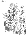
- the outdoor unit 3 is comprised an outdoor casing that includes such things as a bottom plate 41, a right side plate 42, a left side plate 43, a front plate 44, a protective metal net 46, a top plate 47, and a humidification unit casing 48.
- a fan intake port 45 and a divider 49 are installed behind the front plate 44.
- the outdoor heat exchanger 24 is installed in front of the protective metal net 46 that is positioned in the rear of the outdoor unit casing, and is approximately L-(shaped) when viewed from above.
- a fan motor mount 50 is installed in front of the outdoor heat exchanger 24, and the fan motor 30 is fixed thereto.
- the outdoor fan 29 is installed on the outdoor fan motor 30.
- the outdoor fan 29 is driven by the outdoor fan motor 30, and thereby creates a negative pressure in the space formed by the fan intake port 45, the divider 49, the left side plate 43, the outdoor heat exchanger 24, and the bottom plate of the humidification unit casing 48. After the air introduced from the rear surface and the left surface comes into contact with the outdoor heat exchanger 24, it is discharged through the front surface of the front plate 44.
- the components that form the refrigerant circuit such as the compressor 21, the four way directional control valve 22, the electric valve 25, the liquid shut-off valve 27, and the gas shut-off valve 28, and a thermistor 51 for detecting the temperature of each component thereof, are disposed between the divider 49 and the right side plate 42.
- a shut-off valve cover 52 for protecting the liquid shut-off valve 27 and the gas shut-off valve 28 is installed on the right side of the right side plate 42.
- An electric component box 53 is installed above the outdoor fan 29.
- a printed wiring board 54 on which electric components for controlling each portion of the air conditioner are mounted is stored in the electric component box 53, and heat dissipating fins 55 for dissipating heat produced by the electric components are installed on the electric component box 53.
- a fire-proof plate 56 for preventing fire from spreading in the rare instance one breaks out, and a drip-proof plate 57 for preventing the intrusion of drops of water from the humidification unit, are provided in the upper portion of the space in which refrigerant circuit components such as the compressor 21 are stored.
- a humidification rotor 58 is disposed inside the humidification unit casing 48.
- the humidification rotor 58 absorbs moisture from the air that comes into contact therewith, and is a disk shaped member that is made of a porous material such as zeolite and the like that has the ability to release moisture absorbed thereby when it is heated.
- the humidification rotor 58 is rotatively supported by a support shaft 59 that is provided on the humidification unit casing 48.
- Gear teeth are formed on the peripheral surface of the humidification rotor 58, and mesh with a rotor drive gear 62 installed on a drive shaft of a rotor drive motor 61.
- a heater assembly 64 is disposed on the upper surface of the humidification rotor 58 such that it covers approximately half thereof.
- the heater assembly 64 is comprised of a heater main body 66, an upper cover 65 that covers the heater main body 66, and a lower cover 69 that has an intake port 67 for drawing in air and a discharge port 68 that discharges air heated by the heater main body 66.
- the heater assembly 64 is installed above the humidification rotor 58 via a heater fixing plate 63.
- a humidification fan 70 is disposed below the humidification rotor 58 and in a position that faces the heater assembly 64.
- the humidification fan 70 is a centrifugal fan that is disposed inside a casing that links to a humidification connecting duct 72, and is formed to be integral with a humidification fan intake port 71 that is installed below the humidification rotor 58.
- the humidification fan 70 discharges air that passed through the humidification rotor 58 to the humidification connecting duct 72, and sends out humidified air to the indoor unit 2 via a humidification hose 73 and a humidified air line 7.
- An absorption connecting duct 74 is provided on the upper surface of the humidification rotor 58 such that it covers the portion thereof that is not covered by the heater assembly 64.
- the absorption connecting duct 74 forms an air flow path that extends from the lower portion of the humidification rotor 58, passes through the humidification rotor 58, and ends in an absorption discharge path 75 that is adjacent to the area in which the humidification rotor 58 is stored.
- An electric component casing that is composed of the electric component box 76 in which the printed wiring board is stored and an electric component box lid 77 is disposed inside the humidification unit casing 48 together with an electric power source board 79
- Figs. 4 and 5 show a simplified cross-sectional view of the outdoor unit 3.
- the humidification unit 4 is disposed in the upper portion of the outdoor air conditioner 5, and is integrally stored inside the outdoor unit casing 80.
- a divider 81 that divides the humidification unit 4 from the outdoor air conditioning unit 5 is disposed inside the outdoor unit casing 80.
- the absorption discharge path 75 of the humidification unit 4 is disposed above the outdoor fan 29.
- a flow path opening and closing means 82 is provided in the divider 81 positioned between the established space of the outdoor fan 29 and the absorption discharge path 75.
- the flow path opening and closing means 82 is constructed such that it is capable of opening and closing the absorption discharge path 75 and the established space of the outdoor fan 29.
- the absorption discharge path 75 will be open to the negative pressure space generated by the outdoor fan 29, air will flow from the exterior of the outdoor unit casing 80 through the humidification rotor 58, and an air flow will be generated that is discharged through the front surface of the outdoor air conditioning unit 5 via the absorption discharge path 75.
- the air heated by the heating assembly 64 is mixed with the moisture removed from the humidification rotor 58 to become humidified air, and is then transported to the indoor unit 2.
- FIG. 6 An example of the flow path opening and closing means 82 is shown in Figs. 6 and 7.
- a slide plate 92 is provided that is capable of closing a port 91 provided in the divider 81.
- the slide plate 92 is supported such that it is horizontally moveable in Fig. 6 by means of guide members 93, 93.
- a threaded shaft 94 is fixed to one end of the slide plate 92.
- a nut member 96 is provided on a central portion of the threaded shaft 94 that regulates the horizontal movement of the slide plate 92, meshes with the threaded shaft 94, and is supported by the threaded shaft 94 such that it is freely rotatable therewith.
- the peripheral surface of the nut member 96 has a gear formed thereon which meshes with a gear 97 fixed to a rotation shaft of a drive motor 98.
- the nut member 96 rotates via the gear 97, and moves the threaded shaft 94 in the first direction.
- the slide plate 92 fixed to one end of the threaded shaft 94 is guided by the guide members 93, 93 to move it, for example, from the position which closes the port 91 to the position which opens it.
- the threaded shaft 94 will move in the (second) direction.
- the slide plate 92 fixed to one end of the threaded shaft 94 moves together with the threaded shaft 94 and will move from the position in which the port 91 is open to the position in which it is closed.
- the operational mode can be controlled by regulating the aperture.
- the flow path opening and closing means 82 will be completely closed. When this occurs, the air flow through the humidification rotor 58 will be cut off, and thus the air flow produced by the outdoor fan 29 is only for the outdoor heat exchanger 24.
- the flow path opening and closing means 82 will be half open.
- the air flow through the humidification rotor 58 will be restricted by half that when in the fully open state, and thus the air flow to the outdoor heat exchanger 24 will be maintained, the efficiency during heating operations will not be damaged, and humidification operations can be conducted by means of the humidification unit 3.
- the flow path opening and closing means 82 will be fully open.
- the air flow through the humidification flow path will be maximized, and the absorption of moisture during humidification operations can be performed more efficiently.
- the rotational frequency of the outdoor fan 29 will be controlled in response to the outdoor humidity, and the amount of moisture absorbed from the air introduced into the air conditioner 1 will be regulated. This situation is shown in the flowchart of Fig. 10.
- the outdoor humidity is detected in Step S11. If a humidity sensor is provided in the outdoor unit 3, the outdoor humidity can be detected by this humidity sensor. In addition, if an outdoor temperature sensor for detecting the outdoor temperature is provided together with a post-rotor pass through temperature sensor that detects the air temperature after the air has passed through the humidification rotor, the outdoor humidity can be detected from the detected values from the outdoor temperature sensor and the post-rotor pass through temperature sensor.
- Step S12 it is determined whether or not the outdoor humidity is lower than a first predetermined value. If the outdoor humidity is lower than the first predetermined value, the process moves to Step S13.
- Step S13 the rotational frequency of the outdoor fan 29 is set to high.
- the outdoor fan motor 30 that drives the outdoor fan 29 is a DC motor, and thus the rotational frequency thereof can be increased by increasing the frequency of the power supplied to the outdoor fan motor 30.
- Step S14 it is determined whether or not the outdoor humidity is higher than a second predetermined value.
- This second predetermined value is higher than the first predetermined value, and if the outdoor humidity detected is higher than the second predetermined value, then the process moves to Step S15.
- the rotational frequency of the outdoor fan 29 is set to low. Here, the rotational frequency thereof can be lowered by lowering the frequency of the power supplied to the outdoor fan motor 30.
- the aperture of the flow path opening and closing means 82 can be regulated, then when in the humidification operation mode, the aperture can be regulated in response to the outdoor humidity, the amount of air introduced into the air conditioner 1 can be changed, and the amount of moisture absorbed can be regulated. This situation is shown in the flowchart of Fig. 11.
- Step S21 the outdoor humidity is detected.
- the outdoor humidity can be detected by this humidity sensor, and the outdoor humidity can also be detected from the detected values from an outdoor temperature sensor and a post-rotor pass through temperature sensor.
- Step S22 it is determined whether or not the outdoor humidity is lower than a first predetermined value. If the outdoor humidity is lower than the first predetermined value, the process moves to Step S23. In Step S23, the aperture of the flow path opening and closing means 82 is set to high.
- Step S24 it is determined whether or not the outdoor humidity is higher than a second predetermined value. This second predetermined value is higher than the first predetermined value, and if the outdoor humidity detected is higher than the second predetermined value, then the process moves to Step S25. At Step S25, the aperture of the flow path opening and closing means 82 is set to low.
- Tourmaline powder can be mixed into the synthetic resin used to form the casing members around the vicinity of the air discharge ports in the indoor unit 2 and each structural element thereof.
- a paint containing tourmaline powder can be applied to the casing member and each structural element.
- the interior of the humidified air line 7 from the humidification unit 4 to the indoor unit 2, as well as each structural element of the humidification unit 4, can be formed from a synthetic resin containing tourmaline powder, or a paint containing tourmaline powder can be applied thereto.
- the air discharged from the indoor unit 2 can contain a large quantity of negative ions, and thus the generation of oxygen radicals that are deleterious to human health can be reduced and adult diseases such as high blood pressure and the like can be prevented.
- the outdoor fan provided in the outdoor air conditioning unit is used to produce an air flow so that the humidification unit can absorb moisture, which makes it possible to reduce the amount of noise generated when compared to providing an absorption fan in the humidification unit.
- the number of parts such as motors and the like can be reduced, the size of the air conditioner can be reduced, the amount of energy consumed can be reduced, and cost reductions can be achieved.
- the outdoor heat exchanger is positioned on the side of the outdoor fan that produces negative pressure
- the air flow path is constructed such that the air that passed through the hygroscopic member is directed toward and passes through the negative pressure portion between the outdoor heat exchanger and the outdoor fan, and thus this air can be efficiently used when the hygroscopic member absorbs moisture.
- the portion thereof that has absorbed moisture in the air flow path generated by the outdoor fan moves to the heated position, and humidified air can be supplied to the indoor unit through the humidified air line by means of the air flow from the humidification fan.
- the divider can reliably isolate the outdoor fan storage unit from the humidification unit storage unit when the humidification unit is not operating, and an air flow path that passes through the hygroscopic member can be produced by opening the flow path opening and closing means when the humidification unit is operating.
Landscapes
- Engineering & Computer Science (AREA)
- Chemical & Material Sciences (AREA)
- Combustion & Propulsion (AREA)
- Mechanical Engineering (AREA)
- General Engineering & Computer Science (AREA)
- Air Humidification (AREA)
- Other Air-Conditioning Systems (AREA)
- Central Air Conditioning (AREA)
- Air Filters, Heat-Exchange Apparatuses, And Housings Of Air-Conditioning Units (AREA)
- Devices For Blowing Cold Air, Devices For Blowing Warm Air, And Means For Preventing Water Condensation In Air Conditioning Units (AREA)
Abstract
Description
Claims (5)
- An air conditioner, comprising:an outdoor unit casing (80);an outdoor air conditioning unit (5) that comprises an outdoor heat exchanger (24) that is stored inside the outdoor unit casing (80), and an outdoor fan (29) that is stored inside the outdoor unit casing (80) and serves to generate an air flow that exchanges heat between it and the outdoor heat exchanger (24);an indoor unit casing that is disposed in an interior space;an indoor air conditioning unit (2) that comprises an indoor heat exchanger (11) that is stored inside the indoor unit casing;a humidification unit (4) that is rotatively stored inside the outdoor unit casing (80), and which comprises a hygroscopic member (58) that is formed from a hygroscopic material that absorbs moisture from the air and releases this absorbed moisture when it is heated, a drive means (61) for rotatively driving the hygroscopic member (58), a heating means (64) which heats a portion of the hygroscopic member (58), and a humidified air transport means (70, 72, 73) that mixes the moisture removed from the portion of the hygroscopic member (58) heated by the heating means (64) with air and transports this mixture into the indoor unit casing; anda flow path opening and closing means (82) that extends from the exterior of the outdoor unit casing (80) to a portion of the hygroscopic member (58) in which the heating means (64) is not positioned, and which opens and closes the air flow path that discharges air to the outside by means of the outdoor fan (29).
- The air conditioner set forth in claim 1, wherein the outdoor heat exchanger (24) is positioned at least on a rear surface of the outdoor unit casing (80), the outdoor fan (29) is provided on a front surface of the outdoor heat exchanger (24), and the humidification unit (4) is provided on an upper portion of the outdoor heat exchanger (24) and the outdoor fan (29) inside the outdoor unit casing (80).
- The air conditioner set forth in claim 1 or claim 2, wherein the hygroscopic member (58) can be constructed such that it is disk shaped and rotatable about a rotation shaft (59) that extends in a vertical direction.
- The air conditioner set forth in claims 1 to 3, wherein the humidified air transport means comprises a humidification fan (70) that sends air to a portion of the hygroscopic member (58) that is heated by the heating means (64), and humidified air lines (72, 73) for transporting air flow that passed through the heated portion of the hygroscopic member (58) to the indoor unit casing.
- The air conditioner set forth in any of claims 1 to 4, wherein the outdoor unit casing (80) is comprised of a divider (81) that separates, in an airtight manner, an outdoor fan storage unit that stores the outdoor heat exchanger (24) and the outdoor fan (29) from a humidification unit storage unit that stores the humidification unit; andthe flow path opening and closing means (82) can be provided in the divider (81).
Applications Claiming Priority (3)
| Application Number | Priority Date | Filing Date | Title |
|---|---|---|---|
| JP2000276287 | 2000-09-12 | ||
| JP2000276287A JP2002089896A (en) | 2000-09-12 | 2000-09-12 | Air conditioner |
| PCT/JP2001/006569 WO2002023094A1 (en) | 2000-09-12 | 2001-07-30 | Air conditioner |
Publications (3)
| Publication Number | Publication Date |
|---|---|
| EP1326056A1 true EP1326056A1 (en) | 2003-07-09 |
| EP1326056A4 EP1326056A4 (en) | 2005-11-16 |
| EP1326056B1 EP1326056B1 (en) | 2008-07-30 |
Family
ID=18761782
Family Applications (1)
| Application Number | Title | Priority Date | Filing Date |
|---|---|---|---|
| EP01954381A Expired - Lifetime EP1326056B1 (en) | 2000-09-12 | 2001-07-30 | Air conditioner |
Country Status (8)
| Country | Link |
|---|---|
| EP (1) | EP1326056B1 (en) |
| JP (1) | JP2002089896A (en) |
| KR (1) | KR100545074B1 (en) |
| CN (1) | CN1177178C (en) |
| AT (1) | ATE403116T1 (en) |
| DE (1) | DE60135135D1 (en) |
| ES (1) | ES2307634T3 (en) |
| WO (1) | WO2002023094A1 (en) |
Cited By (3)
| Publication number | Priority date | Publication date | Assignee | Title |
|---|---|---|---|---|
| EP2208945A4 (en) * | 2007-10-05 | 2016-11-30 | Daikin Ind Ltd | AIR CONDITIONER |
| EP3236165A4 (en) * | 2014-12-18 | 2018-08-29 | Daikin Industries, Ltd. | Outdoor unit for air conditioner |
| WO2018179014A1 (en) * | 2017-03-28 | 2018-10-04 | Evolving Living Innovation Center E.L.I.C. S.r.l. | Heat pump apparatus for changing air within domestic spaces and respective mode of operation |
Families Citing this family (16)
| Publication number | Priority date | Publication date | Assignee | Title |
|---|---|---|---|---|
| JP3668786B2 (en) * | 2003-12-04 | 2005-07-06 | ダイキン工業株式会社 | Air conditioner |
| CN100445652C (en) * | 2004-03-31 | 2008-12-24 | 大金工业株式会社 | Air Conditioning System |
| JP2008241212A (en) * | 2007-03-28 | 2008-10-09 | Toshiba Carrier Corp | Air conditioner |
| JP5234205B2 (en) * | 2011-06-01 | 2013-07-10 | ダイキン工業株式会社 | Air conditioner outdoor unit |
| JP5862058B2 (en) * | 2011-06-01 | 2016-02-16 | ダイキン工業株式会社 | Air conditioner outdoor unit |
| CN103574789B (en) * | 2012-08-02 | 2016-05-04 | 珠海格力电器股份有限公司 | Dehumidifier with built-in water pump |
| JP5800074B2 (en) * | 2013-09-30 | 2015-10-28 | ダイキン工業株式会社 | Unit outside air conditioning room |
| JP2015068593A (en) * | 2013-09-30 | 2015-04-13 | ダイキン工業株式会社 | Unit outside air conditioning room |
| JP2021055906A (en) * | 2019-09-30 | 2021-04-08 | ダイキン工業株式会社 | Air conditioning system |
| JP6970930B1 (en) * | 2020-10-05 | 2021-11-24 | パナソニックIpマネジメント株式会社 | Air conditioner |
| CN113531675A (en) * | 2021-06-30 | 2021-10-22 | 青岛海尔空调器有限总公司 | Air conditioner outdoor unit and air conditioner |
| CN114838425B (en) * | 2022-03-16 | 2024-02-13 | 广东德尔玛科技股份有限公司 | humidifier |
| CN115751472A (en) * | 2022-10-20 | 2023-03-07 | 青岛海尔空调器有限总公司 | Anhydrous humidification module and air conditioner |
| CN115560409A (en) * | 2022-10-20 | 2023-01-03 | 青岛海尔空调器有限总公司 | Anhydrous humidification module and air conditioner |
| CN115899842A (en) * | 2022-10-20 | 2023-04-04 | 青岛海尔空调器有限总公司 | Anhydrous humidification module and air conditioner |
| CN115899864A (en) * | 2022-10-20 | 2023-04-04 | 青岛海尔空调器有限总公司 | Anhydrous humidification module and air conditioner |
Family Cites Families (8)
| Publication number | Priority date | Publication date | Assignee | Title |
|---|---|---|---|---|
| IL64915A (en) * | 1982-02-02 | 1985-04-30 | Joel Harband | Apparatus and method for temperature and humidity control |
| JP3132940B2 (en) * | 1993-03-02 | 2001-02-05 | 松下電器産業株式会社 | Air conditioner with humidification function |
| JP2919711B2 (en) * | 1993-06-30 | 1999-07-19 | シャープ株式会社 | Air conditioner with humidification function |
| JP3157994B2 (en) * | 1994-10-28 | 2001-04-23 | シャープ株式会社 | Air conditioner with humidification function |
| JP2989513B2 (en) * | 1995-04-03 | 1999-12-13 | シャープ株式会社 | Air conditioner with dehumidification function |
| JP3559421B2 (en) * | 1997-03-27 | 2004-09-02 | シャープ株式会社 | Humidifier |
| JP2000171056A (en) * | 1998-12-04 | 2000-06-23 | Daikin Ind Ltd | Dehumidifying and humidifying unit |
| KR20010026764A (en) * | 1999-09-08 | 2001-04-06 | 윤종용 | Humidifier and an air conditioner having the humidifier |
-
2000
- 2000-09-12 JP JP2000276287A patent/JP2002089896A/en active Pending
-
2001
- 2001-07-30 WO PCT/JP2001/006569 patent/WO2002023094A1/en not_active Ceased
- 2001-07-30 EP EP01954381A patent/EP1326056B1/en not_active Expired - Lifetime
- 2001-07-30 KR KR1020037003606A patent/KR100545074B1/en not_active Expired - Fee Related
- 2001-07-30 ES ES01954381T patent/ES2307634T3/en not_active Expired - Lifetime
- 2001-07-30 AT AT01954381T patent/ATE403116T1/en not_active IP Right Cessation
- 2001-07-30 CN CNB018141048A patent/CN1177178C/en not_active Expired - Fee Related
- 2001-07-30 DE DE60135135T patent/DE60135135D1/en not_active Expired - Lifetime
Cited By (3)
| Publication number | Priority date | Publication date | Assignee | Title |
|---|---|---|---|---|
| EP2208945A4 (en) * | 2007-10-05 | 2016-11-30 | Daikin Ind Ltd | AIR CONDITIONER |
| EP3236165A4 (en) * | 2014-12-18 | 2018-08-29 | Daikin Industries, Ltd. | Outdoor unit for air conditioner |
| WO2018179014A1 (en) * | 2017-03-28 | 2018-10-04 | Evolving Living Innovation Center E.L.I.C. S.r.l. | Heat pump apparatus for changing air within domestic spaces and respective mode of operation |
Also Published As
| Publication number | Publication date |
|---|---|
| EP1326056B1 (en) | 2008-07-30 |
| KR100545074B1 (en) | 2006-01-24 |
| JP2002089896A (en) | 2002-03-27 |
| KR20030045802A (en) | 2003-06-11 |
| EP1326056A4 (en) | 2005-11-16 |
| WO2002023094A1 (en) | 2002-03-21 |
| CN1446301A (en) | 2003-10-01 |
| ES2307634T3 (en) | 2008-12-01 |
| ATE403116T1 (en) | 2008-08-15 |
| DE60135135D1 (en) | 2008-09-11 |
| CN1177178C (en) | 2004-11-24 |
Similar Documents
| Publication | Publication Date | Title |
|---|---|---|
| EP1326056B1 (en) | Air conditioner | |
| CN215260129U (en) | Fresh air component and air conditioner with same | |
| CN111706919A (en) | Double cross-flow air conditioner and air conditioner | |
| CN105745499B (en) | Air-conditioner outdoor unit | |
| AU2002335534B2 (en) | Ventilator and air conditioner | |
| JP4677658B2 (en) | Air conditioner | |
| KR100707440B1 (en) | humidifier | |
| KR20020061594A (en) | Air conditioner | |
| KR100569548B1 (en) | Air conditioner | |
| JP5170181B2 (en) | Air conditioner | |
| JP7617444B2 (en) | Air conditioning indoor unit | |
| CN218096255U (en) | Air treatment module and air conditioning equipment | |
| CN219103235U (en) | Air treatment module and air conditioner | |
| CN105579781B (en) | air conditioner outdoor unit | |
| WO2024083198A1 (en) | Water-free humidification module, and air conditioner | |
| JP3564525B2 (en) | Air conditioner | |
| JP2005069565A (en) | Indoor unit of air conditioner | |
| JP2002071171A (en) | Humidification unit | |
| JP6113989B2 (en) | Outdoor unit | |
| WO2002023095A1 (en) | Air conditioner | |
| JP2002071174A (en) | Humidification unit | |
| KR19980052882U (en) | Air conditioner | |
| JP2002098357A (en) | Air conditioner | |
| KR20020026723A (en) | The ventilation apparatus of air conditioner | |
| CN118328488A (en) | Air treatment module and air conditioner |
Legal Events
| Date | Code | Title | Description |
|---|---|---|---|
| PUAI | Public reference made under article 153(3) epc to a published international application that has entered the european phase |
Free format text: ORIGINAL CODE: 0009012 |
|
| 17P | Request for examination filed |
Effective date: 20030410 |
|
| AK | Designated contracting states |
Designated state(s): AT BE CH CY DE DK ES FI FR GB GR IE IT LI LU MC NL PT SE TR |
|
| A4 | Supplementary search report drawn up and despatched |
Effective date: 20050930 |
|
| RIC1 | Information provided on ipc code assigned before grant |
Ipc: 7F 24F 6/06 B Ipc: 7F 24F 1/00 B Ipc: 7F 24F 6/00 A Ipc: 7F 24F 3/14 B |
|
| 17Q | First examination report despatched |
Effective date: 20061115 |
|
| GRAP | Despatch of communication of intention to grant a patent |
Free format text: ORIGINAL CODE: EPIDOSNIGR1 |
|
| GRAS | Grant fee paid |
Free format text: ORIGINAL CODE: EPIDOSNIGR3 |
|
| GRAA | (expected) grant |
Free format text: ORIGINAL CODE: 0009210 |
|
| AK | Designated contracting states |
Kind code of ref document: B1 Designated state(s): AT BE CH CY DE DK ES FI FR GB GR IE IT LI LU MC NL PT SE TR |
|
| REG | Reference to a national code |
Ref country code: GB Ref legal event code: FG4D |
|
| REG | Reference to a national code |
Ref country code: CH Ref legal event code: EP |
|
| REF | Corresponds to: |
Ref document number: 60135135 Country of ref document: DE Date of ref document: 20080911 Kind code of ref document: P |
|
| REG | Reference to a national code |
Ref country code: IE Ref legal event code: FG4D |
|
| REG | Reference to a national code |
Ref country code: ES Ref legal event code: FG2A Ref document number: 2307634 Country of ref document: ES Kind code of ref document: T3 |
|
| PG25 | Lapsed in a contracting state [announced via postgrant information from national office to epo] |
Ref country code: PT Free format text: LAPSE BECAUSE OF FAILURE TO SUBMIT A TRANSLATION OF THE DESCRIPTION OR TO PAY THE FEE WITHIN THE PRESCRIBED TIME-LIMIT Effective date: 20081230 Ref country code: NL Free format text: LAPSE BECAUSE OF FAILURE TO SUBMIT A TRANSLATION OF THE DESCRIPTION OR TO PAY THE FEE WITHIN THE PRESCRIBED TIME-LIMIT Effective date: 20080730 |
|
| PG25 | Lapsed in a contracting state [announced via postgrant information from national office to epo] |
Ref country code: AT Free format text: LAPSE BECAUSE OF FAILURE TO SUBMIT A TRANSLATION OF THE DESCRIPTION OR TO PAY THE FEE WITHIN THE PRESCRIBED TIME-LIMIT Effective date: 20080730 Ref country code: FI Free format text: LAPSE BECAUSE OF FAILURE TO SUBMIT A TRANSLATION OF THE DESCRIPTION OR TO PAY THE FEE WITHIN THE PRESCRIBED TIME-LIMIT Effective date: 20080730 |
|
| REG | Reference to a national code |
Ref country code: CH Ref legal event code: PL |
|
| PG25 | Lapsed in a contracting state [announced via postgrant information from national office to epo] |
Ref country code: MC Free format text: LAPSE BECAUSE OF NON-PAYMENT OF DUE FEES Effective date: 20080731 Ref country code: BE Free format text: LAPSE BECAUSE OF FAILURE TO SUBMIT A TRANSLATION OF THE DESCRIPTION OR TO PAY THE FEE WITHIN THE PRESCRIBED TIME-LIMIT Effective date: 20080730 |
|
| REG | Reference to a national code |
Ref country code: IE Ref legal event code: MM4A |
|
| PG25 | Lapsed in a contracting state [announced via postgrant information from national office to epo] |
Ref country code: DK Free format text: LAPSE BECAUSE OF FAILURE TO SUBMIT A TRANSLATION OF THE DESCRIPTION OR TO PAY THE FEE WITHIN THE PRESCRIBED TIME-LIMIT Effective date: 20080730 |
|
| PLBE | No opposition filed within time limit |
Free format text: ORIGINAL CODE: 0009261 |
|
| STAA | Information on the status of an ep patent application or granted ep patent |
Free format text: STATUS: NO OPPOSITION FILED WITHIN TIME LIMIT |
|
| PG25 | Lapsed in a contracting state [announced via postgrant information from national office to epo] |
Ref country code: CH Free format text: LAPSE BECAUSE OF NON-PAYMENT OF DUE FEES Effective date: 20080731 Ref country code: LI Free format text: LAPSE BECAUSE OF NON-PAYMENT OF DUE FEES Effective date: 20080731 |
|
| 26N | No opposition filed |
Effective date: 20090506 |
|
| PG25 | Lapsed in a contracting state [announced via postgrant information from national office to epo] |
Ref country code: IE Free format text: LAPSE BECAUSE OF NON-PAYMENT OF DUE FEES Effective date: 20080730 |
|
| PG25 | Lapsed in a contracting state [announced via postgrant information from national office to epo] |
Ref country code: SE Free format text: LAPSE BECAUSE OF FAILURE TO SUBMIT A TRANSLATION OF THE DESCRIPTION OR TO PAY THE FEE WITHIN THE PRESCRIBED TIME-LIMIT Effective date: 20081030 |
|
| PG25 | Lapsed in a contracting state [announced via postgrant information from national office to epo] |
Ref country code: CY Free format text: LAPSE BECAUSE OF FAILURE TO SUBMIT A TRANSLATION OF THE DESCRIPTION OR TO PAY THE FEE WITHIN THE PRESCRIBED TIME-LIMIT Effective date: 20080730 Ref country code: LU Free format text: LAPSE BECAUSE OF NON-PAYMENT OF DUE FEES Effective date: 20080730 |
|
| PG25 | Lapsed in a contracting state [announced via postgrant information from national office to epo] |
Ref country code: TR Free format text: LAPSE BECAUSE OF FAILURE TO SUBMIT A TRANSLATION OF THE DESCRIPTION OR TO PAY THE FEE WITHIN THE PRESCRIBED TIME-LIMIT Effective date: 20080730 |
|
| PG25 | Lapsed in a contracting state [announced via postgrant information from national office to epo] |
Ref country code: GR Free format text: LAPSE BECAUSE OF FAILURE TO SUBMIT A TRANSLATION OF THE DESCRIPTION OR TO PAY THE FEE WITHIN THE PRESCRIBED TIME-LIMIT Effective date: 20081031 |
|
| REG | Reference to a national code |
Ref country code: FR Ref legal event code: PLFP Year of fee payment: 16 |
|
| PGFP | Annual fee paid to national office [announced via postgrant information from national office to epo] |
Ref country code: ES Payment date: 20160613 Year of fee payment: 16 |
|
| PGFP | Annual fee paid to national office [announced via postgrant information from national office to epo] |
Ref country code: FR Payment date: 20160613 Year of fee payment: 16 |
|
| PGFP | Annual fee paid to national office [announced via postgrant information from national office to epo] |
Ref country code: IT Payment date: 20160720 Year of fee payment: 16 Ref country code: GB Payment date: 20160727 Year of fee payment: 16 Ref country code: DE Payment date: 20160726 Year of fee payment: 16 |
|
| REG | Reference to a national code |
Ref country code: DE Ref legal event code: R119 Ref document number: 60135135 Country of ref document: DE |
|
| GBPC | Gb: european patent ceased through non-payment of renewal fee |
Effective date: 20170730 |
|
| REG | Reference to a national code |
Ref country code: FR Ref legal event code: ST Effective date: 20180330 |
|
| PG25 | Lapsed in a contracting state [announced via postgrant information from national office to epo] |
Ref country code: DE Free format text: LAPSE BECAUSE OF NON-PAYMENT OF DUE FEES Effective date: 20180201 Ref country code: GB Free format text: LAPSE BECAUSE OF NON-PAYMENT OF DUE FEES Effective date: 20170730 |
|
| PG25 | Lapsed in a contracting state [announced via postgrant information from national office to epo] |
Ref country code: FR Free format text: LAPSE BECAUSE OF NON-PAYMENT OF DUE FEES Effective date: 20170731 |
|
| PG25 | Lapsed in a contracting state [announced via postgrant information from national office to epo] |
Ref country code: IT Free format text: LAPSE BECAUSE OF NON-PAYMENT OF DUE FEES Effective date: 20170730 |
|
| REG | Reference to a national code |
Ref country code: ES Ref legal event code: FD2A Effective date: 20181029 |
|
| PG25 | Lapsed in a contracting state [announced via postgrant information from national office to epo] |
Ref country code: ES Free format text: LAPSE BECAUSE OF NON-PAYMENT OF DUE FEES Effective date: 20170731 |