EP1326054A1 - Decorative panel for air conditioning system, air outlet unit, and air conditioning system - Google Patents
Decorative panel for air conditioning system, air outlet unit, and air conditioning system Download PDFInfo
- Publication number
- EP1326054A1 EP1326054A1 EP01961228A EP01961228A EP1326054A1 EP 1326054 A1 EP1326054 A1 EP 1326054A1 EP 01961228 A EP01961228 A EP 01961228A EP 01961228 A EP01961228 A EP 01961228A EP 1326054 A1 EP1326054 A1 EP 1326054A1
- Authority
- EP
- European Patent Office
- Prior art keywords
- air
- air vent
- airconditioner
- vent
- lengthwise
- Prior art date
- Legal status (The legal status is an assumption and is not a legal conclusion. Google has not performed a legal analysis and makes no representation as to the accuracy of the status listed.)
- Granted
Links
Images





Classifications
-
- F—MECHANICAL ENGINEERING; LIGHTING; HEATING; WEAPONS; BLASTING
- F24—HEATING; RANGES; VENTILATING
- F24F—AIR-CONDITIONING; AIR-HUMIDIFICATION; VENTILATION; USE OF AIR CURRENTS FOR SCREENING
- F24F1/00—Room units for air-conditioning, e.g. separate or self-contained units or units receiving primary air from a central station
- F24F1/0007—Indoor units, e.g. fan coil units
- F24F1/0011—Indoor units, e.g. fan coil units characterised by air outlets
-
- F—MECHANICAL ENGINEERING; LIGHTING; HEATING; WEAPONS; BLASTING
- F24—HEATING; RANGES; VENTILATING
- F24F—AIR-CONDITIONING; AIR-HUMIDIFICATION; VENTILATION; USE OF AIR CURRENTS FOR SCREENING
- F24F1/00—Room units for air-conditioning, e.g. separate or self-contained units or units receiving primary air from a central station
- F24F1/0007—Indoor units, e.g. fan coil units
- F24F1/0043—Indoor units, e.g. fan coil units characterised by mounting arrangements
- F24F1/0047—Indoor units, e.g. fan coil units characterised by mounting arrangements mounted in the ceiling or at the ceiling
-
- F—MECHANICAL ENGINEERING; LIGHTING; HEATING; WEAPONS; BLASTING
- F24—HEATING; RANGES; VENTILATING
- F24F—AIR-CONDITIONING; AIR-HUMIDIFICATION; VENTILATION; USE OF AIR CURRENTS FOR SCREENING
- F24F13/00—Details common to, or for air-conditioning, air-humidification, ventilation or use of air currents for screening
- F24F13/08—Air-flow control members, e.g. louvres, grilles, flaps or guide plates
- F24F13/10—Air-flow control members, e.g. louvres, grilles, flaps or guide plates movable, e.g. dampers
- F24F13/14—Air-flow control members, e.g. louvres, grilles, flaps or guide plates movable, e.g. dampers built up of tilting members, e.g. louvre
Definitions
- the present invention relates to airconditioner decorative panels, to airconditioner vent units, and to airconditioners. More specifically, the invention relates to structures for a horizontal vane, mounted at an air vent, for controlling the direction in which conditioned air is emitted, and to configurations for an air vent at which such a horizontal vane is mounted.
- horizontal vanes capable of vertically changing the direction in which conditioned air is emitted, are mounted at air vents.
- the emission direction of conditioned air is oriented relatively downward by the horizontal vanes and, on the other hand, during cooling mode of operation, the emission direction is oriented relatively upward so as to be as parallel as possible to a ceiling surface (so-called a "horizontal emission” operation), with a view to achieving a uniform distribution of room temperature during each mode of operation for the purpose of increasing the efficiency of air-conditioning.
- a flow of air emitted from an air vent (a) in a state of "horizontal emission” forms a shape approximately similar to a V-shape along the flow, when viewing the airconditioner from a horizontal direction (see Figure 10 ).
- the velocity of a flow of air emitted at a lengthwise middle portion of the air vent (a) is rapid, so that negative pressure grows stronger, thereby preventing emitted air from reaching a ceiling surface (b) in the vicinity of the air vent.
- ceiling surface fouling is normally found in regions (D) in close proximity to both sides of the air vent (a) and in approximately a V shape, being directed toward the middle portion from the both ends of the air vent (a) as it leaves away from the air vent (a) (see Figure 2 ).
- Japanese Patent Application Kokai Gazette No. H03-160266 proposed a technique in which an auxiliary fin operable to change the emission direction to orient in the direction of a ceiling surface is mounted detachably on a horizontal vane. And, the auxiliary fin is installed and removed, depending on the tendency that ceiling fouling occurs.
- the auxiliary fin is removed and the horizontal vane is oriented downward, for example in an environment likely to cause ceiling fouling because of indoor air that contains dust in large amounts or in a place such as a hospital that requires high levels of contamination prevention.
- the auxiliary fin is installed so that a horizontal emission operation can be performed, for example in an environment unlikely to cause ceiling fouling or in a place that does not require high levels of contamination prevention.
- auxiliary fin Even when an auxiliary fin is provided as in the aforementioned prior art example, the auxiliary fin must be removed in an environment likely to cause ceiling fouling. After all, conditioned air is continuously emitted downward from the air vent. This causes a drop in air-conditioning efficiency during cooling mode of operation in which horizontal emission operation should basically be carried out. Besides, there is another problem that cold air falls directly on a person present in a room. This may cause uncomfortable feeling (so-called "draft feeling”) to the person.
- extension portions (c) are defined at the ends of the air vent (a) as described above
- a horizontal vane (d) is set in a state of "horizontal emission”
- this causes air to flow laterally from the lengthwise middle portion toward the ends of the horizontal vane (d) , as indicated by arrows of Figures 11 .
- the velocity of air emitted from the ends of the air vent (a) is slow, as a result of which the air emitted from the ends of the air vent (a) is likely to reach a ceiling (b) by negative pressure at the middle portion of the air vent (a) . This causes the ceiling surface (b) to become easily dirty.
- an object of the invention is to make it possible to set an adequate emission direction according to the operating status of an airconditioner while, in cases where extension portions are provided at lengthwise ends of an air vent, preventing ceiling fouling by making improvements in the shape of a horizontal vane mounted at the air vent.
- the invention provides improvements to horizontal vanes so that conditioned air is guided, in the inside of an extension portion of an air vent, in a direction substantially orthogonal to the lengthwise direction of the air vent. As a result, the conditioned air is unlikely to flow into the extension portion.
- the invention provides problem-solving means which are premised on a decorative panel for an airconditioner comprising an air vent (16) through which conditioned air is emitted from the direction of a ceiling surface (70) into an indoor space and a horizontal vane (18) , mounted at the air vent (16) , for adjusting the direction in which conditioned air is emitted, on a vent unit for an airconditioner comprising an air vent (16) through which conditioned air is emitted from the direction of a ceiling surface (70) into an indoor space and a horizontal vane (18), mounted at the air vent (16) , for adjusting the direction in which conditioned air is emitted, on an airconditioner comprising the decorative panel (14) which is mounted along a ceiling surface, and on an airconditioner in which the vent unit (51) is mounted on a ceiling surface and is connected, through a fan duct (52) , to an airconditioner main body (53) .
- the air vent (16) has, in the vicinity of an end thereof, an extension portion (16L) so that the lengthwise opening length of the air vent (16) extends at an area facing an indoor space, and the horizontal vane (18) is so formed that, at a position substantially corresponding to an inside end of the extension portion (16L) of the air vent (16) , conditioned air is guided in a direction substantially orthogonal to the lengthwise direction of the air vent (16) .
- the inside end of the extension portion (16L) of the air vent (16) is a lengthwise central side end of the extension portion in the air vent (16) and, preferably the position substantially corresponding to the inside end of the extension portion (16L) is a position located slightly more inwardly than the inside end of the extension portion (16L) .
- conditioned air may be guided in any direction other than the direction in which it (the conditioned air) flows into the extension portion (16L) (the same can be applied to the following).
- the horizontal vane (18) is provided, at a position substantially corresponding to an inside end of the extension portion (16L) of the air vent (16) , with a guide means (18g) for guiding conditioned air in a direction substantially orthogonal to the lengthwise direction of the air vent (16) .
- the guide means (18g) may be composed of a guide plate mounted on an upper surface (18f) of the horizontal vane (18) in a state of horizontal emission.
- the guide plate (18g) is disposed along a direction substantially orthogonal to the lengthwise direction of the horizontal vane (18) ; however, the guide plate (18g) may assume such an inclined position that conditioned air is guided toward the lengthwise center of the air vent (16) .
- the conditioned air when conditioned air is emitted indoors through the air vent (16) , the conditioned air is guided in an approximately horizontal direction at the middle portion of the air vent (16) at which the emission flow velocity is relatively high, during cooling mode of operation. Further, most of conditioned air, which has struck the horizontal vane (18) , will not flow into the extension portion (16L) because of the guide means (18g) , such as a guide plate, mounted on the upper surface (18f) of the horizontal vane (18) , but it flows along the guide plate (18g) and is emitted in an approximately horizontal direction, still at a high flow velocity.
- the guide means (18g) such as a guide plate
- conditioned air striking the horizontal vane (18) flows into the extension portion (16L) ; however, its volume is slight and the volume of air flowing out of the end of the air vent (16) is slight. Because of this, the flow rate of conditioned air, emitted at a slow initial emission velocity and flowing along a ceiling surface, will decrease at the end of the horizontal vane (18) . Further, conditioned air is emitted indoors in downward direction from the entire air vent (16) by adjusting the horizontal vane (18) in downward direction, during heating mode of operation.
- an airflow upstream side end edge in the vicinity of a lengthwise end of the horizontal vane (18) is so formed that conditioned air is allowed to pass in a region substantially corresponding to the extension portion (16L) of the air vent (16) .
- an opening portion (18c) may be defined by notching a part of the horizontal vane (18) .
- conditioned air is guided in an approximately horizontal direction at the middle portion of the air vent (16) at which the emission flow velocity is relatively high.
- a part of conditioned air after passing through the opening portion (18c) in the vicinity of the end of the horizontal vane (18) , is emitted in a more downward direction at the lengthwise end of the air vent (16) at which the emission flow velocity is relatively slow than at the middle portion. Accordingly, the flow rate of conditioned air, emitted at a slow initial velocity at the end of the air vent (16) and flowing along a ceiling surface, decreases.
- the air vent (16) is so formed that conditioned air is emitted in a more downward direction at a sidewall (16b-s) of a lengthwise end region of the air vent (16) substantially corresponding to the extension portion (16L) than at a sidewall (16b-c) of a lengthwise middle portion of the air vent (16) .
- it may be arranged such that the angle of each sidewall of the air vent (16) with respect to the ceiling surface at the lengthwise middle portion differs from that at the lengthwise end.
- conditioned air is emitted definitely in a more downward direction at the lengthwise ends of the air vent (16) at which the emission flow velocity is relatively slow than at the lengthwise middle portion.
- the flow rate of conditioned air, emitted at a slow initial velocity and flowing along a ceiling surface decreases.
- the occurrence of ceiling fouling is prevented while making it possible to allow the emission direction of conditioned air to come closer to a horizontal direction than conventional, particularly during cooling mode of operation which requires horizontal emission of conditioned air.
- This prevents a resident present in the room from having uncomfortable feeling (draft feeling) while securing air-conditioning efficiency.
- the ceiling surface (70) hardly becomes dirty, which does not cause disfigurement of the ceiling surface (70) .
- the ceiling surface (70) requires no cleaning accordingly.
- FIG. 1 is a vertical section showing an arrangement of the ceiling flush type airconditioner (1) according to an embodiment of the invention.
- the airconditioner (1) comprises a casing (10) in which are housed a fan (20) and a heat exchanger (30) .
- the airconditioner (1) is embedded in an installation opening (71) which opens in a ceiling board (ceiling surface) (70) . In this way, the airconditioner (1) is installed in an under-roof space.
- the casing (10) is made up of a box-shaped main body casing (11) which opens downward and a decorative panel (14) with which a bottom opening portion of the main body casing (11) is covered.
- the main body casing (11) is fixedly suspended from an overlying beam or the like by the use of a hanging ring, which is not shown in the Figure. More specifically, the main body casing (11) is made up of an octagonally shaped top plate (12) formed by notching, in a chamfering manner, four comers of a square plate (not shown) and side plates (13) extending downward from the outer edges of the top plate (12) .
- the decorative panel (14) is a plate having a substantially square shape and is attached to the lower ends of the side plates (13) of the main body casing (11) .
- the decorative panel (14) is attached along the ceiling board (70) so that its periphery is brought into abutment with a lower surface of the ceiling board (70) .
- an air inlet (15) is formed in substantially a central portion of the decorative panel (14) so as to open squarely. Formed immediately outside the four sides of the air inlet (15) and in parallel therewith are four rectangular air vents (16) . And, the air inlet (15) is provided, all over its surface, with an air filter (17) for removal of suspended substances such as particulate dust contained in indoor air. The entire lower surface of the air filter (17) is supported by a lattice filter cover.
- the air vent (16) of the decorative panel (14) is defined between an outside guide surface (16a, 16b) which is a side wall on the panel outer peripheral side (on the right-hand side in the Figures) of an air passageway and an inside guide surface (16c, 16d) which is a side wall on the panel inner peripheral side (on the left-hand side in the Figures).
- the outside guide surface (16a, 16b ) is made up of a first outside guide surface (16a) extending substantially vertically downward and a second outside guide surface (16b) inclining, from the lower end of the first outside guide surface (16a) to the lower surface of the decorative panel (14) , obliquely in a downward direction toward the panel outer periphery.
- the second outside guide surface (16b) comprises a middle portion (16b-c) and both ends (16b-s) .
- the middle portion (16b-c) is located longitudinally centrally in the air vent (16) and its inclination with respect to the ceiling surface (70) is set relatively small (an angle of about 30 degrees).
- the both ends (16b-s) are located in the vicinity of both lengthwise ends of the air vent (16) and their inclination to the ceiling surface (70) is set relatively large (an angle of about 60 degrees).
- the inclination of the second outside guide surface (16b) varies gradually from the middle portion (16b-c) toward each end (16b-s) and the angle formed between the second outside guide surface (16b) and the ceiling surface (70) varies continuously.
- Figure 5 which is a perspective view of the air vent (16) when viewed from below, the second outside guide surface (16b) further comprises a lower end edge (16b-e) shaped like a circular arc.
- the inside guide surface (16c, 16d) is made up of a first inside guide surface (16c) which extends substantially vertically downward and a second inside guide surface (16d) which gently inclines obliquely downward toward the panel outer periphery from the lower end of the first inside guide surface (16c) .
- These inside guide surfaces (16c, 16d) are joined together smoothly.
- the outside guide surface (16a, 16b) is formed in an outside member (14a) of the decorative panel (14)
- the inside guide surface (16c, 16d) is formed in an inside member (14b) of the decorative panel (14) .
- the air vent (16) is, as described above, defined between the outside guide surface (16a, 16b) and the inside guide surface (16c, 16d) .
- the horizontal vane (18) capable of vertically adjusting the direction in which conditioned air is emitted is disposed between the outside guide surface (16a, 16b) of the outside member (14a) and the inside guide surface (16c, 16d) of the inside member (14b) .
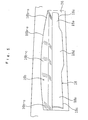
- the horizontal vane (18) is, as depicted in Figure 6 , a long plate member and bends slightly throughout its width direction. Arms (18a, 18a) projecting from an inside surface of the horizontal vane (18) are formed integrally with the both lengthwise ends of the horizontal vane (18) , respectively. Formed at the end of each arm (18a) is a connecting pin (18b) that extends outward along the lengthwise direction of the horizontal vane (18) .
- the horizontal vane (18) is mounted at the air vent (16) in such a way that it can swivel about the connecting pins (18b, 18b). More specifically, the horizontal vane (18) is swiveled about the connecting pins (18b, 18b) by a motor (not shown).
- the horizontal vane (18) is oriented downward when conditioned air is required to be emitted in the most downward direction, as shown in Figure 4 .
- the horizontal vane (18) is so set as to be oriented upward, as shown in Figure 3 .
- the outside guide surface (16a, 16b) bends substantially conformingly to the cross-sectional shape of the horizontal vane (18) (the shape is not limited to such a bent one and any shape may be used as long as it substantially conforms to the shape of the horizontal vane (18) ).
- the inside guide surface (16c, 16d) is so formed as to extend, in totality, more vertically downward than the outside guide surface (16a, 16b) of the outside member (14a) .
- the shape of the inside guide surface (16c, 16d) is a matter of choice.
- these two wall surfaces (the outside guide surface (16a, 16b) and the inside guide surface (16c, 16d)) having the aforesaid shapes and lying face to face with each other, are formed so as to stretch the lengthwise length of the air vent (16) (i.e., in a direction normal to the paper surface of the Figure).
- the air passageway defined between the wall surface (16a, 16b) and the wall surface (16c, 16d) has a function of serving as an "approach way" for adjusting a flow of conditioned air while changing the direction of the conditioned air flow.
- pipes and electrical component boxes are disposed at comers of the main body casing (11) and the decorative panel (14) has four air vents of the same opening shape for the purpose of providing a better exterior appearance, which may produce a difference in the lengthwise opening length of the air passageway between the main body casing's (11) side and the decorative panel's (14) side, as shown in Figure 7.
- the length of the extension portions (16L) varies from one air vent (16) to another depending upon the product embodied according to the invention.
- the inclination of the second outside guide surface (16b) is set according to the foregoing angle setting so that conditioned air is emitted in a more downward direction at sidewalls in regions corresponding to these extension portions (16L) (the both ends (16b-s) of the second outside guide surface (16b)) than at the sidewall (16b-c) of the lengthwise middle portion.
- the middle portion (16b-c) of the sidewall (16b) located longitudinally centrally in the air vent (16) is set at a relatively small angle (about 30 degrees) with respect to the ceiling surface (70) .
- the both ends (16b-s) of the sidewall (16b) are each set at a relatively large angle (about 60 degrees) with respect to the ceiling surface (70) .
- the horizontal vane (18) is so formed as to guide, at its areas substantially corresponding to the inside ends of the extension portions (16L) of the air vent (16) , conditioned air in a direction substantially orthogonal to the lengthwise direction of the air vent (16) . More specifically, the horizontal vane (18) is provided, at its positions substantially corresponding to the inside ends of the extension portions (16L) of the air vent (16) , with guide means (18g) for guiding conditioned air in a direction substantially orthogonal to the lengthwise direction of the air vent (16) . And, each guide means (18g) is composed of a guide plate (18g) mounted on an upper surface (18f) of the horizontal vane (18) in a state of "horizontal emission".
- Each guide plate (18g) is disposed along a direction substantially orthogonal to the lengthwise direction of the horizontal vane (18) .
- the guide plate (18g) may be inclined somewhat so that conditioned air is guided toward the lengthwise center of the air vent (16) .
- notches (18c) as opening portions through which conditioned air is allowed to pass are defined at the airflow upstream side end edges in the vicinity of the both lengthwise ends of the horizontal vane (18) .
- the notches (18c) are formed in regions substantially corresponding to the extension portions (16L) of the air vent (16) . More specifically, the notches (18c) are formed at the airflow upstream side end edges in the vicinity of the both lengthwise ends of the horizontal vane (18) , having a length of approximately a quarter of the lengthwise length of the horizontal vane (18) . Because of the provision of these notches (18c) , the horizontal vane (18) has such a shape that the both ends (18e) have a narrowed width about two thirds of that of the middle portion (18d) .
- the horizontal vane (18) may have for example the following specific dimensions.
- the entire length of the horizontal vane (18) is about 480 mm.
- the width of the horizontal vane (18) (the width of the middle portion (18d)) is about 37 mm.
- the width of each end (18e) is about 25 mm.
- the length of each notch (18c) is about 120 mm.
- the fan (20) is located substantially centrally in the inside of the main body casing (11) .
- This fan is a so-called turbofan in which a blade (23) is held between a shroud (21) and a hub (22) .
- a drive shaft (26) of the fan motor (25) mounted on the top plate (12) of the main body casing (11) is fixedly inserted in the hub (22) of the fan (20) .
- the fan (20) is rotationally driven by driving force of the fan motor (25) , whereby air withdrawn from below the fan (20) is delivered radially laterally.
- a bell-mouth (27) for guiding, to the fan (20) , air that has flowed into the inside of the casing (10) through the air inlet (15) is provided underneath the fan (20) .
- the heat exchanger (30) is a so-called cross fin heat exchanger made up of a large number of plate-like fins (31) which are arranged in parallel with each other and a heat transfer pipe (32) so arranged as to pass through the fins (31) .
- the heat exchanger (30) is formed into a rectangular cylinder, when viewed from top, so as to surround the periphery of the fan (20) .
- the heat exchanger (30) is connected, through a refrigerant pipe (not shown), to an outdoor unit.
- the heat exchanger (30) functions as an evaporator during cooling mode of operation, and as a condenser during heating mode of operation, for controlling the temperature state of air delivered from the fan (20).
- a drain pan (33) for receiving drain water is disposed under the heat exchanger (30) .
- an air circulation passageway (W) extending from the air inlet (15) of the decorative panel (14) to the air vent (16) by way of the air filter (17) , the bell-mouth (27) , the fan (20) , and the heat exchanger (30) , is defined in the inside of the main body casing (11) of the airconditioner (1) .
- indoor air taken into the inside of the casing (10) from the air inlet (15) through the air filter (17) flows in the bell-mouth (27) , in the fan (20) , and in the heat exchanger (30) in that order in the air circulation passageway (W) .
- the indoor air exchanges heat with refrigerant in the heat exchanger (30) and is temperature controlled (cooled during cooling mode of operation and heated during heating mode of operation). Thereafter, the air is emitted, as conditioned air, into an indoor space. In this way, the indoor space is air-conditioned.
- the horizontal vane (18) is oriented substantially vertically downward (see Figure 4 ) so that conditioned air is made to flow along the horizontal vane (18) between the panel outer peripheral side sidewall (16a, 16b) and the panel inner peripheral side sidewall (16c, 16d) of the air vent (16) and is emitted in a downward direction as indicted by Arrow S of the Figure.
- the horizontal vane (18) is turned in an upward direction (see Figure 3 ) so that the upper surface (18f) of the horizontal vane (18) becomes substantially parallel with the middle portion (16b-c) of the second outside guide surface (16b) of the air vent (16).
- conditioned air flows curvedly along the middle portion (18d) of the horizontal vane (18) at the middle portion of the air vent (16) and the direction of its line of flow varies greatly and smoothly.
- Arrow S1 of the Figure the conditioned air passes between the second outside guide surface (16b) on the panel outer peripheral side of the air vent (16) and the horizontal vane (18) .
- the conditioned air is emitted through the air vent (16) at an emission angle as parallel as possible to the lower surface of the ceiling board (70) (for example, at angles of from 30 to 35 degrees with respect to the ceiling board's (70) lower surface).
- air emitted at the both ends of the air vent (16) is unlikely to flow along the lower surface of the ceiling board (70) during cooling mode of operation that especially requires a "horizontal emission” of conditioned air. Therefore, even when the emission direction of conditioned air emitted through the air vent (16) is varied by the horizontal vane (18) so that the angle formed between the conditioned air emission direction and the lower surface of the ceiling board (70) is made to come near to, for example, about 30 to about 35 degrees at the middle portion of the air vent, the occurrence of ceiling fouling can be prevented.
- ceiling fouling is prevented while making it possible to allow the emission direction of conditioned air to come closer to a horizontal direction than conventional, particularly during cooling mode of operation which requires horizontal emission of conditioned air.
- the ceiling surface (70) hardly becomes dirty, therefore circumventing disfigurement of the ceiling surface (70) .
- the ceiling surface (70) requires no cleaning accordingly.
- each notch (18c) of the horizontal vane (18) is formed only in a region of each end (18d) of the horizontal vane (18) whose length is about a quarter of that of the horizontal vane (18) , which makes it possible to achieve, in totality, a satisfactory "horizontal emission” operation while at the same time preventing the occurrence of ceiling fouling.
- the invention is not limited to the above-mentioned embodiment.
- the invention includes other various embodiments.
- a single guide plate (18g) is mounted in the vicinity of each end of the horizontal vane (18) .
- a plurality of guide plates (18g) may be mounted.
- the guide plate (18g) is mounted only on the side of the one end where the extension portion (16L) is provided.
- the invention is applied to the airconditioner (1) of a so-called ceiling flush four-direction emission type which is provided with a turbofan and which emits conditioned air in four directions.
- the invention is not limited to such an application.
- the invention is applicable to an airconditioner of a so-called ceiling flush two-direction emission type which emits conditioned air in two directions.
- the invention is applicable not only to ceiling flush type airconditioners but also to duct type airconditioners.
- the duct type airconditioner (50) is an airconditioner in which a vent unit (51) mounted on the ceiling board (70) is connected, through a fan duct (52) , to an airconditioner main body (53) mounted on a building roof or the like.
- the vent unit (51) of the airconditioner (50) the same effects as obtained in the above-described embodiment can be obtained by provision of a guide plate (18g) at each lengthwise end of the horizontal vane (18) .
- the notches (18c) as opening portions are formed in the vicinity of the both ends (18e) of the horizontal vane (18) .
- the opening portions (18c) are not necessarily provided. Even in cases where such opening portions are provided, through holes may be formed in the horizontal vane (18) in place of the notches (18c) .
- the airflow upstream side end edges may employ any construction as long as conditioned air is emitted in a downward direction at the both ends of the air vent (16) during "horizontal emission" mode of operation.
- the shape and the dimensions of the horizontal vane (18) and the shape and the dimensions of the notch (18c) (the opening portion) shown above are only examples and therefore can of course be altered properly according to the shape and the dimensions of a product embodied according to the invention.
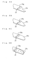
- Figures 9A-9C show horizontal vanes (18) having different ends.
- Figure 9A illustrates an example of the notch (18c) in which airflow upstream side end edges of areas in the vicinity of both lengthwise ends of a horizontal vane (18) are shaped into a circular arc.
- Figure 9B illustrates another example of the notch (18c) in which airflow upstream side end edges of areas in the vicinity of both lengthwise ends of a horizontal vane (18) are obliquely linearly shaped.
- Figure 9C illustrates still another example of the notch (18c) in which airflow upstream side end edges of areas in the vicinity of both lengthwise ends of a horizontal vane (18) are formed into a reversed circular arc with respect to the one shown in Figure 9A .
- Figure 9D shows a substitute for the opening portion (18c) . More specifically, each end of the horizontal vane (18) is formed into a three-dimensionally twisted shape so that the airflow upstream side end edges rise from the lengthwise middle portion toward the both ends of the horizontal vane (18) . In this case, since air is unlikely to separate at the ends of the horizontal vane (18) , the ends of the horizontal vane (18) are unlikely to involve surrounding warm air. This provides an advantage that condensation is unlikely to occur.
- the inclination of the second outside guide surface (16b) of the air vent (16) is set in such a way that the both ends (16b-s) are inclined at an angle nearer to a vertical than the middle portion (16b-c) .
- the second outside guide surface (16b) may be inclined, for example throughout the air vent (16) , correspondingly to the inclination of the middle portion (16b-c) of the above-described embodiment.
Landscapes
- Engineering & Computer Science (AREA)
- Chemical & Material Sciences (AREA)
- Combustion & Propulsion (AREA)
- Mechanical Engineering (AREA)
- General Engineering & Computer Science (AREA)
- Air-Flow Control Members (AREA)
- Duct Arrangements (AREA)
- Air Filters, Heat-Exchange Apparatuses, And Housings Of Air-Conditioning Units (AREA)
Abstract
Description
Claims (14)
- A decorative panel for an airconditioner comprising an air vent (16) through which conditioned air is emitted from the direction of a ceiling surface (70) into an indoor space and a horizontal vane (18), mounted at said air vent (16), for adjusting the direction in which conditioned air is emitted,
wherein:said air vent (16) has, in the vicinity of an end thereof, an extension portion (16L) so that the lengthwise opening length of said air vent (16) extends at an area facing an indoor space, andsaid horizontal vane (18) is so formed that, at a position substantially corresponding to an inside end of said extension portion (16L) of said air vent (16), conditioned air is guided in a direction substantially orthogonal to the lengthwise direction of said air vent (16). - The airconditioner decorative panel of claim 1, wherein said horizontal vane (18) is provided, at a position substantially corresponding to an inside end of said extension portion (16L) of said air vent (16), with guide means (18g) for guiding conditioned air in a direction substantially orthogonal to the lengthwise direction of said air vent (16).
- The airconditioner decorative panel of claim 2, wherein said guide means (18g) is composed of a guide plate mounted on an upper surface (18f) of said horizontal vane (18) in a state of horizontal emission.
- The airconditioner decorative panel of claim 3, wherein said guide plate (18g) is disposed along a direction substantially orthogonal to the lengthwise direction of said horizontal vane (18).
- The airconditioner decorative panel of any one of claims 1-4, wherein an airflow upstream side end edge in the vicinity of a lengthwise end of said horizontal vane (18) is so formed that conditioned air is allowed to pass in a region substantially corresponding to said extension portion (16L) of said air vent (16).
- The airconditioner decorative panel of any one of claims 1-5, wherein said air vent (16) is so formed that conditioned air is emitted in a more downward direction at a sidewall (16b-s) of a lengthwise end region of said air vent (16) substantially corresponding to said extension portion (16L) than at a sidewall (16b-c) of a lengthwise middle portion of said air vent (16).
- A vent unit for an airconditioner comprising an air vent (16) through which conditioned air is emitted from the direction of a ceiling surface (70) into an indoor space and a horizontal vane (18), mounted at said air vent (16), for adjusting the direction in which conditioned air is emitted,
wherein:said air vent (16) has, in the vicinity of an end thereof, an extension portion (16L) so that the lengthwise opening length of said air vent (16) extends at an area facing an indoor space, andsaid horizontal vane (18) is so formed that, at a position substantially corresponding to an inside end of said extension portion (16L) of said air vent (16), conditioned air is guided in a direction substantially orthogonal to the lengthwise direction of said air vent (16). - The airconditioner vent unit of claim 7, wherein said horizontal vane (18) is provided, at a position substantially corresponding to an inside end of said extension portion (16L) of said air vent (16), with guide means (18g) for guiding conditioned air in a direction substantially orthogonal to the lengthwise direction of said air vent (16).
- The airconditioner vent unit of claim 8, wherein said guide means (18g) is composed of a guide plate mounted on an upper surface (18f) of said horizontal vane (18) in a state of horizontal emission.
- The airconditioner vent unit of claim 9, wherein said guide plate (18g) is disposed along a direction substantially orthogonal to the lengthwise direction of said horizontal vane (18).
- The airconditioner vent unit of any one of claims 7-10, wherein an airflow upstream side end edge in the vicinity of a lengthwise end of said horizontal vane (18) is so formed that conditioned air is allowed to pass in a region substantially corresponding to said extension portion (16L) of said air vent (16).
- The airconditioner vent unit of any one of claims 7-11, wherein said air vent (16) is so formed that conditioned air is emitted in a more downward direction at a sidewall (16b-s) of a lengthwise end region of said air vent (16) substantially corresponding to said extension portion (16L) than at a sidewall (16b-c) of a lengthwise middle portion of said air vent (16).
- An airconditioner comprising a decorative panel (14) mounted along a ceiling surface (70),
wherein said decorative panel (14) is composed of a decorative panel according to any one of claims 1-6. - An airconditioner in which a vent unit (51) mounted on a ceiling surface (70) is connected, through a fan duct (52), to an airconditioner main body (53),
wherein said vent unit (51) is composed of a vent unit according to any one of claims 7-12.
Applications Claiming Priority (3)
| Application Number | Priority Date | Filing Date | Title |
|---|---|---|---|
| JP2000269692 | 2000-09-06 | ||
| JP2000269692A JP3624813B2 (en) | 2000-09-06 | 2000-09-06 | Air conditioner decorative panel, air outlet unit, and air conditioner |
| PCT/JP2001/007504 WO2002021051A1 (en) | 2000-09-06 | 2001-08-30 | Decorative panel for air conditioning system, air outlet unit, and air conditioning system |
Publications (3)
| Publication Number | Publication Date |
|---|---|
| EP1326054A1 true EP1326054A1 (en) | 2003-07-09 |
| EP1326054A4 EP1326054A4 (en) | 2005-09-21 |
| EP1326054B1 EP1326054B1 (en) | 2009-04-29 |
Family
ID=18756253
Family Applications (1)
| Application Number | Title | Priority Date | Filing Date |
|---|---|---|---|
| EP01961228A Expired - Lifetime EP1326054B1 (en) | 2000-09-06 | 2001-08-30 | Decorative panel for air conditioning system, air outlet unit, and air conditioning system |
Country Status (7)
| Country | Link |
|---|---|
| EP (1) | EP1326054B1 (en) |
| JP (1) | JP3624813B2 (en) |
| CN (2) | CN1209586C (en) |
| AU (2) | AU8256201A (en) |
| DE (1) | DE60138562D1 (en) |
| ES (1) | ES2323851T3 (en) |
| WO (1) | WO2002021051A1 (en) |
Cited By (11)
| Publication number | Priority date | Publication date | Assignee | Title |
|---|---|---|---|---|
| EP1813878A2 (en) | 2006-01-26 | 2007-08-01 | Lg Electronics Inc. | Indoor unit of air conditioner |
| NL2002265A (en) * | 2008-09-19 | 2010-03-22 | Samsung Electronics Co Ltd | Ceiling type air conditioner. |
| US8342923B2 (en) | 2009-03-16 | 2013-01-01 | Thomas Mavroudis | Cover for environmental control system vent |
| JP2013015311A (en) * | 2011-11-29 | 2013-01-24 | Panasonic Corp | Air conditioner |
| US8460075B2 (en) | 2009-03-16 | 2013-06-11 | Thomas Mavroudis | Cover for wall air conditioning vent |
| EP3006839A1 (en) * | 2014-10-10 | 2016-04-13 | Fujitsu General Limited | Ceiling-embedded air conditioner |
| EP3076088A1 (en) * | 2015-03-31 | 2016-10-05 | Fujitsu General Limited | Ceiling-embedded air conditioner |
| EP3113965A4 (en) * | 2014-03-06 | 2017-10-04 | Dometic Sweden AB | Improved air conditioning system |
| JP2018017421A (en) * | 2016-07-26 | 2018-02-01 | 株式会社富士通ゼネラル | Ceiling-embedded air conditioner |
| US10247441B2 (en) | 2014-11-25 | 2019-04-02 | Mitsubishi Electric Corporation | Refrigeration cycle apparatus with leak detection and associated air flow control |
| EP3745044A4 (en) * | 2018-01-25 | 2021-01-13 | Mitsubishi Electric Corporation | INDOOR UNIT FOR AIR CONDITIONER |
Families Citing this family (22)
| Publication number | Priority date | Publication date | Assignee | Title |
|---|---|---|---|---|
| KR20070078258A (en) * | 2006-01-26 | 2007-07-31 | 엘지전자 주식회사 | Indoor unit of air conditioner |
| US8636566B2 (en) | 2007-09-07 | 2014-01-28 | Toshiba Carrier Corporation | Ceiling-embedded air conditioner |
| JP5194023B2 (en) * | 2007-10-25 | 2013-05-08 | 東芝キヤリア株式会社 | Embedded ceiling air conditioner |
| JP4924697B2 (en) | 2009-11-05 | 2012-04-25 | ダイキン工業株式会社 | Air conditioner indoor unit |
| JP5402616B2 (en) * | 2009-12-24 | 2014-01-29 | 株式会社富士通ゼネラル | Air conditioner |
| WO2012017484A1 (en) * | 2010-08-04 | 2012-02-09 | 三菱電機株式会社 | Indoor unit for air conditioner, and air conditioner |
| JP4864159B1 (en) * | 2010-11-30 | 2012-02-01 | パナソニック株式会社 | Air conditioner |
| JP4947224B1 (en) * | 2011-06-17 | 2012-06-06 | パナソニック株式会社 | Air conditioner |
| JP4911255B1 (en) * | 2011-06-30 | 2012-04-04 | パナソニック株式会社 | Air conditioner |
| JP4947227B1 (en) * | 2011-06-30 | 2012-06-06 | パナソニック株式会社 | Air conditioner |
| JP5131371B1 (en) * | 2011-08-26 | 2013-01-30 | ダイキン工業株式会社 | Air conditioning indoor unit |
| JP5834208B2 (en) * | 2011-11-09 | 2015-12-16 | パナソニックIpマネジメント株式会社 | Air conditioner |
| JP6122241B2 (en) * | 2011-12-28 | 2017-04-26 | ダイキン工業株式会社 | Air conditioning indoor unit |
| WO2015111281A1 (en) * | 2014-01-24 | 2015-07-30 | 東芝キヤリア株式会社 | Air conditioner |
| JP5979454B2 (en) * | 2015-04-23 | 2016-08-24 | パナソニックIpマネジメント株式会社 | Air conditioner |
| JP6344375B2 (en) * | 2015-12-22 | 2018-06-20 | ダイキン工業株式会社 | Indoor unit of air conditioner |
| JP6213853B2 (en) * | 2016-05-27 | 2017-10-18 | パナソニックIpマネジメント株式会社 | Air conditioner |
| JP2018091507A (en) * | 2016-11-30 | 2018-06-14 | 三菱重工サーマルシステムズ株式会社 | Indoor unit for air conditioner |
| EP4596980A3 (en) * | 2016-12-21 | 2025-10-15 | Samsung Electronics Co., Ltd. | Air conditioner |
| WO2018216415A1 (en) * | 2017-05-24 | 2018-11-29 | ダイキン工業株式会社 | Indoor unit for air conditioner |
| JP6566063B2 (en) * | 2018-02-28 | 2019-08-28 | 株式会社富士通ゼネラル | Embedded ceiling air conditioner |
| CN111322746B (en) * | 2020-03-11 | 2021-06-22 | 深圳机械院建筑设计有限公司 | Air outlet layout structure of building central air conditioner |
Family Cites Families (12)
| Publication number | Priority date | Publication date | Assignee | Title |
|---|---|---|---|---|
| JP3136832B2 (en) * | 1993-04-05 | 2001-02-19 | ダイキン工業株式会社 | Air conditioner indoor unit |
| JP2891041B2 (en) * | 1993-06-25 | 1999-05-17 | 三菱電機株式会社 | Grill with shutter |
| JP3438323B2 (en) * | 1994-06-01 | 2003-08-18 | ダイキン工業株式会社 | Ceiling embedded air conditioner and horizontal blade structure of the device |
| JP3240854B2 (en) * | 1994-09-26 | 2001-12-25 | 三菱電機株式会社 | Air conditioner outlet |
| JP3019743B2 (en) * | 1995-04-11 | 2000-03-13 | ダイキン工業株式会社 | Air conditioner |
| JP3531282B2 (en) * | 1995-05-16 | 2004-05-24 | ダイキン工業株式会社 | Wind direction adjustment structure of ceiling embedded type air conditioner |
| JPH0914742A (en) * | 1995-06-29 | 1997-01-17 | Mitsubishi Heavy Ind Ltd | Air conditioner |
| JPH10141701A (en) * | 1996-11-12 | 1998-05-29 | Matsushita Electric Ind Co Ltd | Indoor unit of air conditioner |
| JP2943751B2 (en) * | 1997-01-20 | 1999-08-30 | ダイキン工業株式会社 | Air conditioner |
| JP3188406B2 (en) * | 1997-02-24 | 2001-07-16 | 松下電器産業株式会社 | Ceiling-mounted air conditioner |
| JP3240977B2 (en) * | 1997-10-17 | 2001-12-25 | ダイキン工業株式会社 | Air conditioner |
| JP3957927B2 (en) * | 1999-08-30 | 2007-08-15 | 三菱重工業株式会社 | Embedded ceiling air conditioner |
-
2000
- 2000-09-06 JP JP2000269692A patent/JP3624813B2/en not_active Expired - Fee Related
-
2001
- 2001-08-30 AU AU8256201A patent/AU8256201A/en active Pending
- 2001-08-30 WO PCT/JP2001/007504 patent/WO2002021051A1/en not_active Ceased
- 2001-08-30 DE DE60138562T patent/DE60138562D1/en not_active Expired - Lifetime
- 2001-08-30 EP EP01961228A patent/EP1326054B1/en not_active Expired - Lifetime
- 2001-08-30 ES ES01961228T patent/ES2323851T3/en not_active Expired - Lifetime
- 2001-08-30 AU AU2001282562A patent/AU2001282562B2/en not_active Ceased
- 2001-09-04 CN CNB011326921A patent/CN1209586C/en not_active Expired - Fee Related
- 2001-09-05 CN CN01263618U patent/CN2509505Y/en not_active Expired - Lifetime
Cited By (13)
| Publication number | Priority date | Publication date | Assignee | Title |
|---|---|---|---|---|
| EP1813878A3 (en) * | 2006-01-26 | 2009-07-01 | Lg Electronics Inc. | Indoor unit of air conditioner |
| EP1813878A2 (en) | 2006-01-26 | 2007-08-01 | Lg Electronics Inc. | Indoor unit of air conditioner |
| NL2002265A (en) * | 2008-09-19 | 2010-03-22 | Samsung Electronics Co Ltd | Ceiling type air conditioner. |
| US8342923B2 (en) | 2009-03-16 | 2013-01-01 | Thomas Mavroudis | Cover for environmental control system vent |
| US8460075B2 (en) | 2009-03-16 | 2013-06-11 | Thomas Mavroudis | Cover for wall air conditioning vent |
| JP2013015311A (en) * | 2011-11-29 | 2013-01-24 | Panasonic Corp | Air conditioner |
| EP3113965A4 (en) * | 2014-03-06 | 2017-10-04 | Dometic Sweden AB | Improved air conditioning system |
| AU2015226832B2 (en) * | 2014-03-06 | 2019-05-16 | Dometic Sweden Ab | Improved air conditioning system |
| EP3006839A1 (en) * | 2014-10-10 | 2016-04-13 | Fujitsu General Limited | Ceiling-embedded air conditioner |
| US10247441B2 (en) | 2014-11-25 | 2019-04-02 | Mitsubishi Electric Corporation | Refrigeration cycle apparatus with leak detection and associated air flow control |
| EP3076088A1 (en) * | 2015-03-31 | 2016-10-05 | Fujitsu General Limited | Ceiling-embedded air conditioner |
| JP2018017421A (en) * | 2016-07-26 | 2018-02-01 | 株式会社富士通ゼネラル | Ceiling-embedded air conditioner |
| EP3745044A4 (en) * | 2018-01-25 | 2021-01-13 | Mitsubishi Electric Corporation | INDOOR UNIT FOR AIR CONDITIONER |
Also Published As
| Publication number | Publication date |
|---|---|
| CN1209586C (en) | 2005-07-06 |
| AU8256201A (en) | 2002-03-22 |
| CN1342874A (en) | 2002-04-03 |
| DE60138562D1 (en) | 2009-06-10 |
| JP2002081733A (en) | 2002-03-22 |
| CN2509505Y (en) | 2002-09-04 |
| ES2323851T3 (en) | 2009-07-27 |
| EP1326054A4 (en) | 2005-09-21 |
| JP3624813B2 (en) | 2005-03-02 |
| WO2002021051A1 (en) | 2002-03-14 |
| AU2001282562B2 (en) | 2005-10-20 |
| EP1326054B1 (en) | 2009-04-29 |
Similar Documents
| Publication | Publication Date | Title |
|---|---|---|
| EP1326054B1 (en) | Decorative panel for air conditioning system, air outlet unit, and air conditioning system | |
| AU2002231424B2 (en) | Decorative panel and diffuser unit of air conditioner, and air conditioner | |
| US9897335B2 (en) | Indoor unit of air conditioning apparatus | |
| JP3438684B2 (en) | Ceiling embedded air conditioner | |
| KR100344593B1 (en) | Air-conditioner | |
| CN2442168Y (en) | Ceiling mosaic air conditioner | |
| CN107076430A (en) | Air conditioner | |
| EP1316760B1 (en) | Decorative panel for air conditioning system, air outlet blow-off unit, and air conditioning system | |
| JPH09166353A (en) | Air conditioner | |
| JP3285023B2 (en) | Ceiling-mounted air conditioner | |
| JPH08152187A (en) | Air conditioner | |
| JP3120959B2 (en) | Blower | |
| CN110431360A (en) | air conditioner | |
| JPH0960904A (en) | Air conditioner | |
| JP2516786Y2 (en) | Ceiling-mounted air conditioner | |
| JP2706383B2 (en) | Ceiling-mounted air conditioner | |
| JP2910628B2 (en) | Air conditioner | |
| JP2552551Y2 (en) | Ceiling-mounted air conditioner | |
| JPH0669642U (en) | Ceiling mounted air conditioner | |
| JPH0322655Y2 (en) |
Legal Events
| Date | Code | Title | Description |
|---|---|---|---|
| PUAI | Public reference made under article 153(3) epc to a published international application that has entered the european phase |
Free format text: ORIGINAL CODE: 0009012 |
|
| 17P | Request for examination filed |
Effective date: 20030319 |
|
| AK | Designated contracting states |
Designated state(s): AT BE CH CY DE DK ES FI FR GB GR IE IT LI LU MC NL PT SE TR |
|
| AX | Request for extension of the european patent |
Extension state: AL LT LV MK RO SI |
|
| RBV | Designated contracting states (corrected) |
Designated state(s): BE DE ES FR GB IT |
|
| A4 | Supplementary search report drawn up and despatched |
Effective date: 20050804 |
|
| 17Q | First examination report despatched |
Effective date: 20060921 |
|
| GRAP | Despatch of communication of intention to grant a patent |
Free format text: ORIGINAL CODE: EPIDOSNIGR1 |
|
| GRAS | Grant fee paid |
Free format text: ORIGINAL CODE: EPIDOSNIGR3 |
|
| GRAA | (expected) grant |
Free format text: ORIGINAL CODE: 0009210 |
|
| AK | Designated contracting states |
Kind code of ref document: B1 Designated state(s): BE DE ES FR GB IT |
|
| REG | Reference to a national code |
Ref country code: GB Ref legal event code: FG4D |
|
| REF | Corresponds to: |
Ref document number: 60138562 Country of ref document: DE Date of ref document: 20090610 Kind code of ref document: P |
|
| REG | Reference to a national code |
Ref country code: ES Ref legal event code: FG2A Ref document number: 2323851 Country of ref document: ES Kind code of ref document: T3 |
|
| PG25 | Lapsed in a contracting state [announced via postgrant information from national office to epo] |
Ref country code: BE Free format text: LAPSE BECAUSE OF FAILURE TO SUBMIT A TRANSLATION OF THE DESCRIPTION OR TO PAY THE FEE WITHIN THE PRESCRIBED TIME-LIMIT Effective date: 20090429 |
|
| PLBE | No opposition filed within time limit |
Free format text: ORIGINAL CODE: 0009261 |
|
| STAA | Information on the status of an ep patent application or granted ep patent |
Free format text: STATUS: NO OPPOSITION FILED WITHIN TIME LIMIT |
|
| 26N | No opposition filed |
Effective date: 20100201 |
|
| PGFP | Annual fee paid to national office [announced via postgrant information from national office to epo] |
Ref country code: DE Payment date: 20140827 Year of fee payment: 14 |
|
| PGFP | Annual fee paid to national office [announced via postgrant information from national office to epo] |
Ref country code: FR Payment date: 20140808 Year of fee payment: 14 Ref country code: ES Payment date: 20140711 Year of fee payment: 14 Ref country code: GB Payment date: 20140827 Year of fee payment: 14 |
|
| PGFP | Annual fee paid to national office [announced via postgrant information from national office to epo] |
Ref country code: IT Payment date: 20140819 Year of fee payment: 14 |
|
| REG | Reference to a national code |
Ref country code: DE Ref legal event code: R119 Ref document number: 60138562 Country of ref document: DE |
|
| GBPC | Gb: european patent ceased through non-payment of renewal fee |
Effective date: 20150830 |
|
| PG25 | Lapsed in a contracting state [announced via postgrant information from national office to epo] |
Ref country code: IT Free format text: LAPSE BECAUSE OF NON-PAYMENT OF DUE FEES Effective date: 20150830 |
|
| REG | Reference to a national code |
Ref country code: FR Ref legal event code: ST Effective date: 20160429 |
|
| PG25 | Lapsed in a contracting state [announced via postgrant information from national office to epo] |
Ref country code: DE Free format text: LAPSE BECAUSE OF NON-PAYMENT OF DUE FEES Effective date: 20160301 Ref country code: GB Free format text: LAPSE BECAUSE OF NON-PAYMENT OF DUE FEES Effective date: 20150830 |
|
| PG25 | Lapsed in a contracting state [announced via postgrant information from national office to epo] |
Ref country code: FR Free format text: LAPSE BECAUSE OF NON-PAYMENT OF DUE FEES Effective date: 20150831 |
|
| PG25 | Lapsed in a contracting state [announced via postgrant information from national office to epo] |
Ref country code: ES Free format text: LAPSE BECAUSE OF NON-PAYMENT OF DUE FEES Effective date: 20150831 |
|
| REG | Reference to a national code |
Ref country code: ES Ref legal event code: FD2A Effective date: 20180710 |