EP1326043A2 - Flexible tube - Google Patents
Flexible tube Download PDFInfo
- Publication number
- EP1326043A2 EP1326043A2 EP02028652A EP02028652A EP1326043A2 EP 1326043 A2 EP1326043 A2 EP 1326043A2 EP 02028652 A EP02028652 A EP 02028652A EP 02028652 A EP02028652 A EP 02028652A EP 1326043 A2 EP1326043 A2 EP 1326043A2
- Authority
- EP
- European Patent Office
- Prior art keywords
- small
- interlock pipe
- diameter
- flexible tube
- interlock
- Prior art date
- Legal status (The legal status is an assumption and is not a legal conclusion. Google has not performed a legal analysis and makes no representation as to the accuracy of the status listed.)
- Granted
Links
Images



Classifications
-
- F—MECHANICAL ENGINEERING; LIGHTING; HEATING; WEAPONS; BLASTING
- F01—MACHINES OR ENGINES IN GENERAL; ENGINE PLANTS IN GENERAL; STEAM ENGINES
- F01N—GAS-FLOW SILENCERS OR EXHAUST APPARATUS FOR MACHINES OR ENGINES IN GENERAL; GAS-FLOW SILENCERS OR EXHAUST APPARATUS FOR INTERNAL-COMBUSTION ENGINES
- F01N13/00—Exhaust or silencing apparatus characterised by constructional features
- F01N13/18—Construction facilitating manufacture, assembly, or disassembly
- F01N13/1805—Fixing exhaust manifolds, exhaust pipes or pipe sections to each other, to engine or to vehicle body
- F01N13/1811—Fixing exhaust manifolds, exhaust pipes or pipe sections to each other, to engine or to vehicle body with means permitting relative movement, e.g. compensation of thermal expansion or vibration
- F01N13/1816—Fixing exhaust manifolds, exhaust pipes or pipe sections to each other, to engine or to vehicle body with means permitting relative movement, e.g. compensation of thermal expansion or vibration the pipe sections being joined together by flexible tubular elements only, e.g. using bellows or strip-wound pipes
-
- F—MECHANICAL ENGINEERING; LIGHTING; HEATING; WEAPONS; BLASTING
- F16—ENGINEERING ELEMENTS AND UNITS; GENERAL MEASURES FOR PRODUCING AND MAINTAINING EFFECTIVE FUNCTIONING OF MACHINES OR INSTALLATIONS; THERMAL INSULATION IN GENERAL
- F16L—PIPES; JOINTS OR FITTINGS FOR PIPES; SUPPORTS FOR PIPES, CABLES OR PROTECTIVE TUBING; MEANS FOR THERMAL INSULATION IN GENERAL
- F16L27/00—Adjustable joints; Joints allowing movement
- F16L27/10—Adjustable joints; Joints allowing movement comprising a flexible connection only
- F16L27/1004—Adjustable joints; Joints allowing movement comprising a flexible connection only introduced in exhaust pipes for hot gases
-
- F—MECHANICAL ENGINEERING; LIGHTING; HEATING; WEAPONS; BLASTING
- F16—ENGINEERING ELEMENTS AND UNITS; GENERAL MEASURES FOR PRODUCING AND MAINTAINING EFFECTIVE FUNCTIONING OF MACHINES OR INSTALLATIONS; THERMAL INSULATION IN GENERAL
- F16L—PIPES; JOINTS OR FITTINGS FOR PIPES; SUPPORTS FOR PIPES, CABLES OR PROTECTIVE TUBING; MEANS FOR THERMAL INSULATION IN GENERAL
- F16L27/00—Adjustable joints; Joints allowing movement
- F16L27/10—Adjustable joints; Joints allowing movement comprising a flexible connection only
- F16L27/107—Adjustable joints; Joints allowing movement comprising a flexible connection only the ends of the pipe being interconnected by a flexible sleeve
- F16L27/11—Adjustable joints; Joints allowing movement comprising a flexible connection only the ends of the pipe being interconnected by a flexible sleeve the sleeve having the form of a bellows with multiple corrugations
Definitions
- the present invention relates to a structure of a flexible tube including an interlock pipe and a bellows tube.
- a flexible tube 1A has an outer blade 3, which is placed on the outer peripheral side of a bellows tube 9 having a bellows portion 9c, and an interlock pipe 4, which is placed on the inner peripheral side of the bellows tube 9.
- Each of straight portions 2a of the bellows tube 9, and corresponding one of end portions 3a of the outer blade 3 are placed with being overlaid on the outer peripheral face of the interlock pipe 4.
- a protector 5 is placed on the outer peripheral side of the end portion 3a of the outer blade 3. The protector 5, the straight portion 2a, and the end portion 3a are welded to the outer peripheral face of the interlock pipe 4.
- the inner peripheral diameter of the bellows portion 9c of the bellows tube 9 is set to be larger than that of the straight portion 2a, so that a gap is formed between the bellows portion and the outer peripheral face of the interlock pipe 4. Even when the flexible tube 1A swings due to vibrations of the engine or the like, therefore, the outer peripheral face of the interlock pipe 4 and the bellows portion 9c are prevented from contacting with each other.
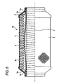
- a flexible tube 1B which is structured as described above and has a long total length as shown in Fig. 6, when the flexible tube 1B vibrates, the swing amplitude of the interlock pipe 4 is larger as the length is larger. As a result, the outer peripheral face of the interlock pipe 4 and the bellows portion 9c contact with each other, thereby causing troubles such as noises.
- a flexible tube including a bellows tube, an interlock pipe, and restriction means.
- the bellows tube has a bellow portion and straight portions, which is formed both ends thereof.
- the interlock pipe in which a plurality of annular plate members or spirally wound band plates are flexibly coupled at side edges thereof to one another through an interlock mechanism, is disposed inside the bellows tube to have a common axis.
- the restriction means is disposed on the bellow portion and serves as a fulcrum to restrict vibration amplitude of the interlock pipe when the interlock pipe is vibrated.
- Inner diameter of the straight portions tube is larger than that of first small-diameter parts of the bellow portion. Inner peripheral surfaces of the straight portions are fixed to an outer surface of the interlock pipe.
- the bellow portion has a second small-diameter part, inner diameter of which is smaller than that of the first small-diameter parts.
- An inner peripheral tip of the second small-diameter part abuts against the outer peripheral surface of the interlock pipe to define the restriction means.
- the restriction means is a buffer member disposed between an inner peripheral tip of at least one of the first small-diameter parts and the outer peripheral surface of the interlock pipe.
- the bellow portion has a second small-diameter part, inner diameter of which is smaller than that of the first small-diameter parts.
- the restriction means is a buffer member disposed between an inner peripheral tip of the second small-diameter part and the outer peripheral surface of the interlock pipe.
- the bellow portion has third small-diameter parts, inner diameter of which smaller than that of the first small-diameter part.
- the restriction means is a buffer member, which is disposed between an inner peripheral tip of at least one of the first small-diameter parts and the outer peripheral surface of the interlock pipe so that the third small-diameter parts holds the buffer member in the axial direction.
- the restriction means is a plurality of restriction members arranged in the axial direction at a predetermined interval.
- Fig. 1 is a section view of an embodiment.
- a flexible tube 1 has an outer blade 3 including a braided tube, which is placed on the outer peripheral side of a bellows tube 2 having a bellows portion 2c, and an interlock pipe 4, which is placed inside the bellows tube 2.
- Each of straight portions 2a of the bellows tube 2, and corresponding one of end portions 3a of the outer blade 3 are overlaid on the outer peripheral face of the interlock pipe 4.
- a protector 5 is placed on the outer peripheral side of the end portion 3a of the outer blade 3. The outer end portion of the protector 5 is squeezed so that the inner peripheral face thereof matches the outer peripheral face of the end portion 3a. The inner end portion of the protector 5 elongates toward the inner side in the axial direction while the diameter thereof is expanded to coincide with the usual outer peripheral diameter of the outer blade 3.
- the protector 5, the straight portion 2a of the bellows tube, and the end portion 3a of the outer blade 3 are welded to the outer peripheral face of the interlock pipe 4.
- the usual diameter of the small-diameter parts of the bellows portion 2c of the bellows tube 2 is set to be larger than the inner peripheral diameter of the straight portion 2a, so that a gap is formed between the interlock pipe 4 and the bellows tube 2.
- a small-diameter part 6a in the vicinity of a center portion in an axial direction is set to have a smaller diameter.
- the small-diameter part 6a constitutes a restricting member in the invention.
- the interlock pipe 4 and the tip end of the small-diameter part 6a contact with each other at the point A in a rattle-free condition. Even when the interlock pipe 4 vibrates, troubles such as noises are not caused in the point A.
- the interlock pipe 4 vibrates with using the point A and points B as fulcrums.
- the points B are boundaries between the straight portions 2a in both the ends of the bellows tube 2 and the bellows portion 2c.
- the addition of the point A reduces the distance between the fulcrums. In accordance with this reduction, the deflection amount of the interlock pipe 4 is reduced, and the vibration amplitude of the interlock pipe 4 is decreased. Even when the flexible tube 1 has a long total length, any portion of the interlock pipe 4 other than the point A does not contact with the bellows portion 2c of the bellows tube 2 because the distance between the fulcrums is short.
- the embodiment is configured as described above.
- the amplitude thereof can be reduced since the addition of a swing fulcrum by means of the small-diameter part 6a. Therefore, the gap between the interlock pipe 4 and the bellows tube 2 can be reduced.
- the outer diameter of the flexible tube can be made smaller than that of a flexible tube according to the related art which uses a bellows tube having uniform crest height (crest height refers to difference between small-diameter parts and large-diameter parts in a bellows portion).
- the gap between the interlock pipe 4 and the bellows tube 2 can be reduced, and in accordance with the reduced gap the crest height of the bellows tube can be increased. Therefore, the flexibility of the bellows tube can be improved, and the value of stress produced in the bellows tube can be reduced. Accordingly, the strength can be enhanced.
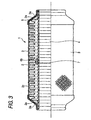
- Fig. 3 shows a second embodiment.
- a small-diameter part 6b in the vicinity of a center portion of the bellows portion 2c of the bellows tube 2 in an axial direction has a smaller diameter at which the small-diameter part does not butt against the interlock pipe 4.
- a buffer member 7 is attached in a gap between an inner peripheral end of the small-diameter part 6b and the interlock pipe 4 so that the small-diameter part 6b restricts the swing of the interlock pipe 4 through the buffer member 7.
- the buffer member 7 is attached to a place in the vicinity of a center of the interlock pipe 4 corresponding to the small-diameter part 6b, by spot welding or the like.
- the small-diameter part 6b and the buffer member 7 attached to the interlock pipe 4 constitute the restricting member in the invention.
- the small-diameter part 6b is set to have a smaller diameter so that the small-diameter part does not butt against the interlock pipe 4.
- the invention is not limited to this.
- the diameter of the small-diameter part 6b may be maintained to the usual diameter, and the buffer member 7 may be attached in the gap between the inner peripheral end of the small-diameter part 6b and the interlock pipe 4.
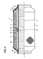
- Fig. 4 shows a third embodiment.
- a buffer member 10 is placed between in a gap between a small-diameter part 8 in the vicinity of a center of the bellows portion 2c in an axial direction and the interlock pipe 4.
- Each of small-diameter parts 6c on both sides of the small-diameter part 8 are set to have smaller diameter so that the small-diameter parts 6c do not butt against the interlock pipe 4.
- the buffer member 10 is clamped between the small-diameter parts 6c to restrict its axial movement.
- the buffer member 10 held by the small-diameter parts 6c butts against the interlock pipe 4, whereby the swing of the interlock pipe 4 can be restricted.
- the buffer member 10, and the small-diameter parts 8 and 6c of the bellows portion 2c constitute the restricting member in the invention.
- the buffer member 10 since the buffer member 10 is held at both the sides by the small-diameter parts 6c, the buffer member does not slip off even when the buffer member is not fixed to the small-diameter part 8 by welding or the like.
- one fulcrum of the swing of the interlock pipe 4 is disposed in the vicinity of the center of the bellows tube 2 with using the small-diameter part 6a, 6b, 6c, or 8 or the buffer member 7 or 10.
- a plurality of fulcrums may be disposed with using a plurality of small-diameter parts 6a, 6b, 6c, or 8 or buffer members 7 or 10.
- the fulcrum of the swing of the interlock pipe 4 is disposed in the vicinity of the center.
- the fulcrum may be disposed in another predetermined position.
- the buffer member 7 is attached to the interlock pipe 4.
- the buffer member may be fixed to the small-diameter part 6b.
- the fulcrum of the swing of the interlock pipe is added by the small-diameter part, the distance between the fulcrums is shortened, and hence the deflection amount of the interlock pipe is reduced.
- the vibration amplitude of the interlock pipe is reduced, and it is not necessary to excessively enlarge the gap between the bellows portion of the bellows tube and the interlock pipe, whereby the size and the like of the flexible tube can be reduced.
- vibrations of the interlock pipe can be restricted by a simple structure without using an additional member.
- the gap between the small-diameter part of the bellows portion of the bellows tube and the interlock pipe is filled with using a buffer member, troubles such as noises can be prevented from occurring.
- the buffer member can be held without using an additional member, and the amplitude of the interlock pipe can be restricted by the buffer member.
- the number of fulcrums of vibrations of the interlock pipe is increased by disposing a plurality of restricting means, and hence vibrations of the interlock pipe can be restricted more surely.
Landscapes
- Engineering & Computer Science (AREA)
- General Engineering & Computer Science (AREA)
- Mechanical Engineering (AREA)
- Chemical & Material Sciences (AREA)
- Combustion & Propulsion (AREA)
- Exhaust Silencers (AREA)
- Joints Allowing Movement (AREA)
- Pipe Accessories (AREA)
Abstract
Description
Claims (6)
- A flexible tube comprising:wherein inner diameter of the straight portions tube is larger than that of first small-diameter parts of the bellow portion; anda bellows tube (2) having a bellow portion (2c) and straight portions (2a), which is formed both ends thereof;an interlock pipe (4) in which a plurality of annular plate members or spirally wound band plates are flexibly coupled at side edges thereof to one another through an interlock mechanism (5), the interlock pipe disposed inside the bellows tube to have a common axis,
wherein inner peripheral surfaces of the straight portions are fixed to an outer surface of the interlock pipe,
the flexible tube characterized by comprising:restriction means (A, 7, 10) disposed on the bellow portion (2c), for serving as a fulcrum to restrict vibration amplitude of the interlock pipe (4) when the interlock pipe (4) is vibrated. - The flexible tube according to claim 1,
wherein the bellow portion (2c) has a second small-diameter part (6a), inner diameter of which is smaller than that of the first small-diameter parts; and
wherein an inner peripheral tip of the second small-diameter part (6a) abuts against the outer peripheral surface of the interlock pipe (4) to define the restriction means (A). - The flexible tube according to claim 1, wherein the restriction means is a buffer member (7, 10) disposed between an inner peripheral tip of at least one of the first small-diameter parts and the outer peripheral surface of the interlock pipe (4).
- The flexible tube according to claim 1,
wherein the bellow portion (2c) has a second small-diameter part (6b), inner diameter of which is smaller than that of the first small-diameter parts; and
wherein the restriction means is a buffer member (7, 10) disposed between an inner peripheral tip of the second small-diameter part (6b) and the outer peripheral surface of the interlock pipe (4). - The flexible tube according to claim 1,
wherein the bellow portion (2c) has third small-diameter parts (6c), inner diameter of which smaller than that of the first small-diameter part; and
wherein the restriction means is a buffer member (10), which is disposed between an inner peripheral tip of at least one of the first small-diameter parts and the outer peripheral surface of the interlock pipe (4) so that the third small-diameter parts (6c) holds the buffer member (10) in the axial direction. - The flexible tube according to any one of claims 1 to 5, wherein the restriction means (A, 7, 10) is a plurality of restriction means (A, 7, 10) arranged in the axial direction at a predetermined interval.
Applications Claiming Priority (2)
| Application Number | Priority Date | Filing Date | Title |
|---|---|---|---|
| JP2001391845 | 2001-12-25 | ||
| JP2001391845A JP3995470B2 (en) | 2001-12-25 | 2001-12-25 | Flexible Tube |
Publications (3)
| Publication Number | Publication Date |
|---|---|
| EP1326043A2 true EP1326043A2 (en) | 2003-07-09 |
| EP1326043A3 EP1326043A3 (en) | 2004-01-02 |
| EP1326043B1 EP1326043B1 (en) | 2006-03-08 |
Family
ID=19188564
Family Applications (1)
| Application Number | Title | Priority Date | Filing Date |
|---|---|---|---|
| EP02028652A Expired - Lifetime EP1326043B1 (en) | 2001-12-25 | 2002-12-20 | Flexible tube |
Country Status (4)
| Country | Link |
|---|---|
| US (1) | US6848478B2 (en) |
| EP (1) | EP1326043B1 (en) |
| JP (1) | JP3995470B2 (en) |
| DE (1) | DE60209630T2 (en) |
Families Citing this family (36)
| Publication number | Priority date | Publication date | Assignee | Title |
|---|---|---|---|---|
| DE10393976T5 (en) * | 2002-12-26 | 2005-11-10 | Hirotec Corp. | Flexible tube |
| DE20302657U1 (en) * | 2003-02-19 | 2003-10-16 | Witzenmann GmbH, 75175 Pforzheim | Flexible pipe element |
| US7748749B2 (en) * | 2004-07-16 | 2010-07-06 | Westfalia Metallschlauchtechnik Gmbh & Co. Kg | Decoupling element impervious to liquid fluids |
| US8733405B2 (en) | 2005-03-14 | 2014-05-27 | Advanced Drainage Systems, Inc. | Corrugated pipe with outer layer |
| US7484535B2 (en) * | 2005-03-14 | 2009-02-03 | Advanced Drainage Systems, Inc. | Corrugated pipe with outer layer |
| KR100735940B1 (en) * | 2005-06-15 | 2007-07-06 | 주식회사 에스제이엠 | Flexible tube for car exhaust pipe |
| DE102005048479A1 (en) * | 2005-10-07 | 2007-04-12 | Westfalia Metallschlauchtechnik Gmbh & Co. Kg | Metal hose arrangement for use as decoupling unit for exhaust gas lines of motor vehicle, has inner hose with fourth mantle shaft winding connected with outer hose between start and end of hose arrangement at welded joint |
| CA2622695C (en) * | 2007-02-26 | 2015-11-03 | Advanced Drainage Systems, Inc. | Pipe extrusion die flow path apparatus and method |
| CA2622692C (en) * | 2007-02-26 | 2015-10-06 | Advanced Drainage Systems, Inc. | Defined ratio dual-wall pipe die |
| US20080290538A1 (en) * | 2007-05-23 | 2008-11-27 | Biesenberger Jeffrey J | Extruder ramp-up control system and method |
| DE202007014303U1 (en) * | 2007-10-12 | 2009-02-19 | Witzenmann Gmbh | Flexible duct element for an exhaust system |
| DE102007052243A1 (en) * | 2007-11-02 | 2009-05-07 | Daimler Ag | Exhaust pipe component |
| US7650912B2 (en) * | 2007-11-06 | 2010-01-26 | Sjm Co., Ltd. | Flexible conduit element |
| US8820800B2 (en) * | 2007-11-16 | 2014-09-02 | Advanced Drainage Systems, Inc. | Multi-wall corrugated pipe couplings and methods |
| US8820801B2 (en) * | 2007-11-16 | 2014-09-02 | Advanced Drainage System, Inc. | Multi-wall corrugated pipe couplings and methods |
| US8114324B2 (en) | 2008-10-14 | 2012-02-14 | Advanced Drainage Systems, Inc. | Apparatus and method for pressing an outer wall of pipe |
| US20100089074A1 (en) * | 2008-10-14 | 2010-04-15 | Sutton Gerald S | Apparatus and Method for Cooling an Outer Wall of Pipe |
| US7988438B2 (en) * | 2008-02-11 | 2011-08-02 | Advanced Drainage Systems, Inc. | Extrusion die vacuum seals |
| US8550807B2 (en) * | 2008-05-28 | 2013-10-08 | Advanced Drainage Systems, Inc. | In-mold punch apparatus and methods |
| DE102010037162B4 (en) * | 2009-08-31 | 2018-05-03 | Westfalia Metallschlauchtechnik Gmbh & Co. Kg | Damping element for decoupling elements, in particular for diaphragm bellows |
| JP4815522B2 (en) * | 2009-09-30 | 2011-11-16 | 本田技研工業株式会社 | Flexible Tube |
| JP5758087B2 (en) * | 2010-06-02 | 2015-08-05 | 矢崎総業株式会社 | Wire harness |
| US20120112452A1 (en) * | 2010-11-09 | 2012-05-10 | Stalcup Ii Robert Franklin | Compressible exhaust connection member |
| US8382165B2 (en) * | 2010-11-09 | 2013-02-26 | Tru-Flex Metal Hose, Llc | Exhaust connection member with preformed braided cover |
| FR2971575B1 (en) * | 2011-02-11 | 2013-12-13 | Snecma | DUCT COMPONENT WITH REDUCED LOAD LOSS |
| KR101480355B1 (en) * | 2013-03-12 | 2015-01-09 | 주식회사 에스제이엠 | Flexible Tube for Exhaust Pipe of Automobiles |
| US9512772B2 (en) | 2013-09-16 | 2016-12-06 | KATCON USA, Inc. | Flexible conduit assembly |
| KR101570921B1 (en) * | 2014-01-22 | 2015-11-20 | 주식회사 에스제이엠 | Flexible Tube for Exhaust Pipe of Automobiles |
| EP3167173B1 (en) * | 2014-07-10 | 2021-03-24 | Witzenmann GmbH | Line assembly |
| EP3183485B1 (en) | 2014-08-21 | 2020-12-16 | American Boa Inc. | Floating load ring for flexible joint |
| US10302231B2 (en) * | 2015-07-13 | 2019-05-28 | Exotic Metals Forming Company LLC | Flexible joint assembly for high or low temperature fluid systems |
| DE202015104177U1 (en) * | 2015-07-30 | 2015-12-03 | Westfalia Metallschlauchtechnik Gmbh & Co. Kg | Arrangement of a conduit element consisting of an inner and outer element |
| DE102017103551A1 (en) * | 2017-02-21 | 2018-08-23 | Witzenmann Gmbh | Conduit element to compensate for strains and / or relative movements |
| US10669919B2 (en) * | 2017-07-06 | 2020-06-02 | American Boa, Inc. | Self-restraining abrasion prevention exhaust conduit |
| CN111765307B (en) * | 2020-07-08 | 2021-08-31 | 中国地震局工程力学研究所 | A large displacement protection device for gas pipeline |
| JP7587552B2 (en) * | 2022-06-30 | 2024-11-20 | 矢崎総業株式会社 | Exterior material, exterior material connector, wire harness, and method for manufacturing wire harness |
Family Cites Families (14)
| Publication number | Priority date | Publication date | Assignee | Title |
|---|---|---|---|---|
| FR2032068A5 (en) * | 1969-02-18 | 1970-11-20 | Mapegaz | Bellows pipe - joint |
| GB1380762A (en) * | 1971-11-25 | 1975-01-15 | Kirchner F | Protective sheath for flexible shafts |
| DE2216772A1 (en) * | 1972-04-07 | 1973-10-18 | Kali Chemie Ag | ELASTIC MOUNT FOR CERAMIC MONOLITHIC CATALYST BODY |
| DE3321559A1 (en) * | 1983-06-15 | 1984-12-20 | Vdo Adolf Schindling Ag, 6000 Frankfurt | DEVICE FOR ELECTRICALLY MEASURING A LIQUID LEVEL |
| KR960006037Y1 (en) * | 1994-12-28 | 1996-07-20 | 성진기공 주식회사 | Connecting device for exhaust gas pipe |
| JP3570814B2 (en) | 1996-03-15 | 2004-09-29 | 三恵技研工業株式会社 | Flexible joint |
| EP0797039B1 (en) * | 1996-03-20 | 2002-10-16 | Witzenmann GmbH | Pipe member having a metal bellows |
| DE29701625U1 (en) * | 1997-01-31 | 1997-03-20 | Witzenmann GmbH Metallschlauch-Fabrik Pforzheim, 75175 Pforzheim | Flexible pipe element for exhaust pipes |
| DE29707908U1 (en) * | 1997-05-02 | 1998-09-03 | Witzenmann GmbH Metallschlauch-Fabrik Pforzheim, 75175 Pforzheim | Flexible pipe element |
| DE19722603C1 (en) * | 1997-05-30 | 1998-08-13 | Witzenmann Metallschlauchfab | More durable flexible tube section for hot exhaust gases from vehicular internal combustion engines |
| JPH11153267A (en) | 1997-09-23 | 1999-06-08 | Witzenmann Gmbh Metallschlauchfab Pforzheim | Tube element |
| DE19820863A1 (en) * | 1998-05-09 | 1999-11-18 | Witzenmann Metallschlauchfab | Flexible pipe element |
| DE19821596A1 (en) * | 1998-05-14 | 1999-11-25 | Witzenmann Metallschlauchfab | Agraff hose for exhaust systems of motor vehicles |
| NO335033B1 (en) * | 2000-05-10 | 2014-08-25 | Itp | Pipe with double pipe wall and high bending stiffness |
-
2001
- 2001-12-25 JP JP2001391845A patent/JP3995470B2/en not_active Expired - Fee Related
-
2002
- 2002-12-20 EP EP02028652A patent/EP1326043B1/en not_active Expired - Lifetime
- 2002-12-20 DE DE60209630T patent/DE60209630T2/en not_active Expired - Fee Related
- 2002-12-23 US US10/326,882 patent/US6848478B2/en not_active Expired - Lifetime
Also Published As
| Publication number | Publication date |
|---|---|
| EP1326043A3 (en) | 2004-01-02 |
| DE60209630D1 (en) | 2006-05-04 |
| US20030150502A1 (en) | 2003-08-14 |
| JP3995470B2 (en) | 2007-10-24 |
| US6848478B2 (en) | 2005-02-01 |
| DE60209630T2 (en) | 2006-08-10 |
| EP1326043B1 (en) | 2006-03-08 |
| JP2003194270A (en) | 2003-07-09 |
Similar Documents
| Publication | Publication Date | Title |
|---|---|---|
| US6848478B2 (en) | Flexible tube | |
| KR100281630B1 (en) | Decoupler for Automobile Exhaust Pipe | |
| CA2517688C (en) | A flexible tube for an exhaust pipe of an automobile | |
| US20080084065A1 (en) | Exhaust pipe connecting device | |
| EP0974741A1 (en) | Flexible tube of an exhaust pipe for motor vehicles | |
| KR100602770B1 (en) | Flexible tube for automobile exhaust pipe | |
| JP2006234046A (en) | Vibration isolator | |
| JP2819868B2 (en) | Flexible pipe device for exhaust pipe | |
| JP4034112B2 (en) | Flexible Tube | |
| JPH11125290A (en) | Cylindrical vibration isolator | |
| JPH04331891A (en) | Flexible pipe device for exhaust pipe | |
| JP7044469B2 (en) | Anti-vibration device | |
| JPH10315789A (en) | Engine support device | |
| JP3049050U (en) | Flexible pipe | |
| JP2005104427A (en) | Exhaust mount rubber | |
| JP2005113837A (en) | Spacer member for exhaust pipes of double-pipe type | |
| JP4688056B2 (en) | Dynamic damper and exhaust system structure including the same | |
| JP2009063063A (en) | Mounting structure of dynamic damper | |
| KR100492081B1 (en) | Flexible Tube For Vehicle Exhaust Pipe | |
| JP5082301B2 (en) | Flexible Tube | |
| KR100361078B1 (en) | Decoupler for exhaust pipe of an automobil | |
| JP4664262B2 (en) | Dynamic damper | |
| JP2001342829A (en) | Exhaust pipe connection structure of internal combustion engine | |
| JPH10153113A (en) | Flexible tube for automobile exhaust system and manufacturing method thereof | |
| JPH08193515A (en) | Spherical joint |
Legal Events
| Date | Code | Title | Description |
|---|---|---|---|
| PUAI | Public reference made under article 153(3) epc to a published international application that has entered the european phase |
Free format text: ORIGINAL CODE: 0009012 |
|
| AK | Designated contracting states |
Designated state(s): AT BE BG CH CY CZ DE DK EE ES FI FR GB GR IE IT LI LU MC NL PT SE SI SK TR |
|
| AX | Request for extension of the european patent |
Extension state: AL LT LV MK RO |
|
| PUAL | Search report despatched |
Free format text: ORIGINAL CODE: 0009013 |
|
| AK | Designated contracting states |
Kind code of ref document: A3 Designated state(s): AT BE BG CH CY CZ DE DK EE ES FI FR GB GR IE IT LI LU MC NL PT SE SI SK TR |
|
| AX | Request for extension of the european patent |
Extension state: AL LT LV MK RO |
|
| 17P | Request for examination filed |
Effective date: 20040204 |
|
| 17Q | First examination report despatched |
Effective date: 20040416 |
|
| AKX | Designation fees paid |
Designated state(s): DE FR GB |
|
| GRAP | Despatch of communication of intention to grant a patent |
Free format text: ORIGINAL CODE: EPIDOSNIGR1 |
|
| GRAS | Grant fee paid |
Free format text: ORIGINAL CODE: EPIDOSNIGR3 |
|
| GRAA | (expected) grant |
Free format text: ORIGINAL CODE: 0009210 |
|
| AK | Designated contracting states |
Kind code of ref document: B1 Designated state(s): DE FR GB |
|
| REG | Reference to a national code |
Ref country code: GB Ref legal event code: FG4D |
|
| REF | Corresponds to: |
Ref document number: 60209630 Country of ref document: DE Date of ref document: 20060504 Kind code of ref document: P |
|
| ET | Fr: translation filed | ||
| PLBE | No opposition filed within time limit |
Free format text: ORIGINAL CODE: 0009261 |
|
| STAA | Information on the status of an ep patent application or granted ep patent |
Free format text: STATUS: NO OPPOSITION FILED WITHIN TIME LIMIT |
|
| 26N | No opposition filed |
Effective date: 20061211 |
|
| PGFP | Annual fee paid to national office [announced via postgrant information from national office to epo] |
Ref country code: FR Payment date: 20081212 Year of fee payment: 7 |
|
| PGFP | Annual fee paid to national office [announced via postgrant information from national office to epo] |
Ref country code: DE Payment date: 20081219 Year of fee payment: 7 |
|
| PGFP | Annual fee paid to national office [announced via postgrant information from national office to epo] |
Ref country code: GB Payment date: 20081217 Year of fee payment: 7 |
|
| REG | Reference to a national code |
Ref country code: GB Ref legal event code: 746 Effective date: 20090924 |
|
| GBPC | Gb: european patent ceased through non-payment of renewal fee |
Effective date: 20091220 |
|
| REG | Reference to a national code |
Ref country code: FR Ref legal event code: ST Effective date: 20100831 |
|
| PG25 | Lapsed in a contracting state [announced via postgrant information from national office to epo] |
Ref country code: FR Free format text: LAPSE BECAUSE OF NON-PAYMENT OF DUE FEES Effective date: 20091231 |
|
| PG25 | Lapsed in a contracting state [announced via postgrant information from national office to epo] |
Ref country code: DE Free format text: LAPSE BECAUSE OF NON-PAYMENT OF DUE FEES Effective date: 20100701 |
|
| PG25 | Lapsed in a contracting state [announced via postgrant information from national office to epo] |
Ref country code: GB Free format text: LAPSE BECAUSE OF NON-PAYMENT OF DUE FEES Effective date: 20091220 |