EP1326037A1 - Rotation axis seal device and helium gas turbine power generation system using the same - Google Patents
Rotation axis seal device and helium gas turbine power generation system using the same Download PDFInfo
- Publication number
- EP1326037A1 EP1326037A1 EP02000121A EP02000121A EP1326037A1 EP 1326037 A1 EP1326037 A1 EP 1326037A1 EP 02000121 A EP02000121 A EP 02000121A EP 02000121 A EP02000121 A EP 02000121A EP 1326037 A1 EP1326037 A1 EP 1326037A1
- Authority
- EP
- European Patent Office
- Prior art keywords
- gas
- pressure
- gas pressure
- section
- space
- Prior art date
- Legal status (The legal status is an assumption and is not a legal conclusion. Google has not performed a legal analysis and makes no representation as to the accuracy of the status listed.)
- Withdrawn
Links
- 239000007789 gas Substances 0.000 title claims description 494
- 239000001307 helium Substances 0.000 title claims description 125
- 229910052734 helium Inorganic materials 0.000 title claims description 125
- SWQJXJOGLNCZEY-UHFFFAOYSA-N helium atom Chemical compound [He] SWQJXJOGLNCZEY-UHFFFAOYSA-N 0.000 title claims description 125
- 238000010248 power generation Methods 0.000 title claims description 25
- 238000000034 method Methods 0.000 claims description 6
- 238000007789 sealing Methods 0.000 claims description 3
- 230000001105 regulatory effect Effects 0.000 description 20
- 230000007423 decrease Effects 0.000 description 13
- 238000010586 diagram Methods 0.000 description 5
- 230000001276 controlling effect Effects 0.000 description 3
- 238000012423 maintenance Methods 0.000 description 3
- 230000008569 process Effects 0.000 description 3
- 230000008859 change Effects 0.000 description 2
- 230000008878 coupling Effects 0.000 description 2
- 238000010168 coupling process Methods 0.000 description 2
- 238000005859 coupling reaction Methods 0.000 description 2
- 239000003921 oil Substances 0.000 description 2
- 230000004044 response Effects 0.000 description 2
- 230000009471 action Effects 0.000 description 1
- 230000006835 compression Effects 0.000 description 1
- 238000007906 compression Methods 0.000 description 1
- 230000003247 decreasing effect Effects 0.000 description 1
- 239000010687 lubricating oil Substances 0.000 description 1
- 239000000203 mixture Substances 0.000 description 1
- 230000004048 modification Effects 0.000 description 1
- 238000012986 modification Methods 0.000 description 1
- 238000000926 separation method Methods 0.000 description 1
Images



Classifications
-
- F—MECHANICAL ENGINEERING; LIGHTING; HEATING; WEAPONS; BLASTING
- F16—ENGINEERING ELEMENTS AND UNITS; GENERAL MEASURES FOR PRODUCING AND MAINTAINING EFFECTIVE FUNCTIONING OF MACHINES OR INSTALLATIONS; THERMAL INSULATION IN GENERAL
- F16J—PISTONS; CYLINDERS; SEALINGS
- F16J15/00—Sealings
- F16J15/16—Sealings between relatively-moving surfaces
- F16J15/34—Sealings between relatively-moving surfaces with slip-ring pressed against a more or less radial face on one member
- F16J15/3404—Sealings between relatively-moving surfaces with slip-ring pressed against a more or less radial face on one member and characterised by parts or details relating to lubrication, cooling or venting of the seal
Definitions
- the present invention relates to a rotation axis seal device and a helium gas turbine power generation system, which uses the shaft seal device and generates electric power by rotating a gas turbine using helium gas.
- a helium gas turbine power generation system As one of atomic generation systems, a helium gas turbine power generation system is developed.
- helium gas is used as a primary system gas supplied from a high temperature gas reactor like a nuclear reactor, and a gas turbine is rotated with the helium gas to generate electric power.
- a gas turbine and a generator are accommodated in a pressure vessel in which the primary system helium gas is circulated. Because the pressure vessel is radioactively polluted with the primary system helium gas, a lot of processes are needed for the maintenance of the pressure vessel.
- an object of the present invention is to provide a helium gas turbine power generation system, in which a pressure vessel can be made small in size.
- Another object of the present invention is to provide a helium gas turbine power generation system in which a turbine is arranged in a pressure vessel and a generator is arranged outside the pressure vessel.
- Still another object of the present invention is to provide a rotation axis seal device which can prevent the leakage of gas in a rotary shaft.
- an axis seal device is provided between a vessel filled with a first gas of a first gas pressure and a rotation axis as a rotary shaft which passes through the vessel.
- the axis seal device includes first to third dry gas seal sections.
- the first dry gas seal section is provided between the rotation axis and the vessel such that the rotation axis is rotatable, and has a first space section with a second gas pressure.
- the second dry gas seal section is provided subsequently to the first dry gas seal section between the rotation axis and the vessel such that the rotation axis is rotatable, and has a second space section with a third gas pressure.
- the third dry gas seal section is provided subsequently to the second dry gas seal section between the rotation axis and the vessel such that the rotation axis is rotatable, and has a third space section with a fourth gas pressure.
- the first gas pressure is lower than the second gas pressure
- the second gas pressure is higher than the third gas pressure
- the third gas pressure is higher than the fourth gas pressure and an atmospheric pressure
- the fourth gas pressure is lower than the atmospheric pressure.
- the first dry gas seal section may include a first gas pressure control section which controls the second gas pressure such that the second gas pressure is higher than the first gas pressure.
- the first gas pressure control section may include a first pressure sensor provided in the vessel to sense the first gas pressure; a second pressure sensor provided in the first space section to sense the second gas pressure; a gas supply unit which supplies gas of a gas pressure higher than the second gas pressure into the first space section; and a valve connected with the first space section and the gas supply unit.
- a first control section controls the valve for the gas supply unit to supply the gas into the first space section based on the first gas pressure sensed by the first pressure sensor and the second gas pressure sensed by the second pressure sensor such that the second gas pressure is higher than the first gas pressure.
- the first control section controls the valve based on the first gas pressure sensed by the first pressure sensor and the second gas pressure sensed by the second pressure sensor for the gas supply unit to supply the gas into the first space section to have a hysteresis characteristic in a predetermined first range.
- the first space section may defined by the rotation axis, a wall of the axis seal device, a first dry gas seal and a second dry gas seal, and the first dry gas seal is opened to an inside of the vessel, and the second dry gas seal is shared by the second space section.
- the third dry gas seal section may include a third gas pressure control section which controls the fourth gas pressure such that the fourth gas pressure is lower than the third gas pressure and the atmospheric pressure.
- the third gas pressure control section may include a fourth pressure sensor provided in the third space section to sense the fourth gas pressure; and a gas exhausting unit connected the third second space section.
- a third control section controls the gas exhausting unit based on the fourth gas pressure sensed by the fourth pressure sensor such that the fourth gas pressure is lower than the third gas pressure and the atmospheric pressure.
- the third control section controls the gas exhausting unit to have a hysteresis characteristic in a predetermined third range based on the fourth gas pressure sensed by the fourth pressure sensor such that the fourth gas pressure is lower than the third gas pressure and the atmospheric pressure.
- the third space section may be defined by the rotation axis, a wall of the axis seal device, a third dry gas seal and a labyrinth seal, and the labyrinth seal is opened to atmosphere, and the third dry gas seal is shared by the second space section.
- the second dry gas seal section may include a second gas pressure control section which controls the third gas pressure such that the third gas pressure is lower than the second gas pressure and higher than the atmospheric pressure.
- the second gas pressure control section may include a third pressure sensor provided in the second space section to sense the third gas pressure; and a gas recirculation unit which recirculates gas from the second space section into the first space section.
- a second control section controls the gas recirculation unit based on the third gas pressure sensed by the third pressure sensor such that the third gas pressure is lower than the second gas pressure and higher than the atmospheric pressure.
- the second control section controls the gas recirculation unit to have a hysteresis characteristic in a predetermined second range based on the third gas pressure sensed by the third pressure sensor such that the third gas pressure is lower than the second gas pressure and always higher than the atmospheric pressure.
- the second space section may be defined by the rotation axis, a wall of the axis seal device, a second dry gas seal and a third dry gas seal, and the second dry gas seal is shared by the first space section and the third dry gas seal is shared by the third space section.
- the second dry gas seal section may include N dry gas seal subsections (N is an integer more than 1) connected in series, and the second space section may include N space subsections.
- An M-th(2 ⁇ M ⁇ N) one of the N dry gas seal subsections may include: a M-th space subsection; and a second gas pressure control section which controls an M-th gas pressure of the M-th space subsection such that the M-th gas pressure of the M-th space subsection is lower than an (M-1)-th gas pressure of an (M-1)-th space subsection and higher than an (M+1)-th gas pressure of an (M+1)-th space subsection and the atmospheric pressure.
- the M-th gas pressure control section may include: a M-th pressure sensor provided in the M-th space subsection to sense the M-th gas pressure; and a M-th gas recirculation unit which recirculates gas from the M-th space subsection into the (M-1)-th space subsection.
- An M-th control section controls the M-th gas recirculation unit based on the M-th gas pressure sensed by the M-th pressure sensor such that the M-th gas pressure of the M-th space subsection is lower than an (M-1)-th gas pressure of an (M-1)-th space subsection and higher than an (M+1)-th gas pressure of an (M+1)-th space subsection and the atmospheric pressure.
- the M-th control section controls the M-th gas recirculation unit to have a hysteresis characteristic in a predetermined range based on the M-th gas pressure sensed by the M-th pressure sensor such that the M-th gas pressure of the M-th space subsection is lower than an (M-1)-th gas pressure of an (M-1)-th space subsection and higher than an (M+1)-th gas pressure of an (M+1)-th space subsection and the atmospheric pressure.
- the M-th space subsection may be defined by the rotation axis, a wall of the axis seal device, an (M-1)-th dry gas seal and an M-th dry gas seal, and the (M-1)-th dry gas seal is shared by the (M-1)-th space subsection and the M-th dry gas seal is shared by the (M+1)-th space section.
- the gas may be a helium gas, and is in a temperature range of 700 °C to 1000 °C.
- a gas turbine power generation system may include: a gas reactor which heats up the gas to produce a hot gas; the vessel connected to the gas reactor; a turbine accommodated in the vessel and rotated by the hot gas; a separator member provided for the vessel and the turbine to separate an inside of the vessel into first and second portions; a power generator provided outside the vessel and connected to the turbine by the rotation axis; and the axis seal device described above, provided between the rotation axis and the vessel.
- the gas turbine power generation system may further include a circulating unit which circulates the hot gas from the second portion into the first portion.
- a method of sealing between a first portion filled with a gas and a second portion in atmosphere is achieved by providing first to third space sections between the first portion and the second portion; by controlling a second gas pressure in the first space section to be higher than a first gas pressure in a first portion; by controlling a third gas pressure in the second space section to be lower than a fourth gas pressure in the third space section and to be higher than an atmospheric pressure; and by controlling the fourth gas pressure to be lower than the atmospheric pressure.
- a first dry gas seal is provided between the first portion and the first space section
- a second dry gas seal is provided between the first space section and the second space section
- a third dry gas seal is provided between the second space section and the third space section.
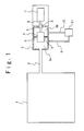
- Fig. 1 is a schematic diagram showing the structure of the helium gas turbine power generation system of the present invention.
- the helium gas turbine power generation system of the present invention contains a high temperature gas reactor 1 which supplies hot helium gas in a temperature range of 700 °C to 1,000 °C to a pressure vessel 3 through a pipe 2.
- the turbine 4 is accommodated in the pressure vessel 3.
- a separation member 5 is provided to separate the internal space of the pressure vessel 3 around the turbine 4 into a first portion 3a as an inner circumference section and a second portion 3b as an outer circumference section.
- the first portion 3a is connected with the pipe 2, but the second portion 3b is not connected with the pipe 2. Therefore, the helium gas is supplied from the high temperature gas reactor 1 to the first portion 3a through the pipe 2, passes through the turbine 4 and then is supplied to the second portion 3b. In this way, the turbine 4 with turbine blades (not shown) is rotated with the hot helium gas supplied from the high temperature gas reactor 1 into the turbine 4.
- the turbine 4 is connected with a generator 7 by a rotation axis 6 as a rotary shaft.
- the generator 7 is arranged outside the pressure vessel 3, and the rotation axis 6 penetrates the wall of the pressure vessel 3.
- An axis seal device 8 is provided between the pressure vessel 3 and the rotation axis 6.
- the axis seal device 8 does not prevent the rotation of the rotation axis 6 and has a function to prevent the helium gas circulating in the pressure vessel 3 from leaking out from the pressure vessel 3.
- the structures of the rotation axis 6 and axis seal device 8 will be described later in detailed.
- the helium turbine power generation system is further composed of a pipe 9 for connecting the first portion 3a and a heat exchanger 11, and a pipe 10 for connecting the second portion 3b and the heat exchanger 11.
- the heat exchanger 11 acquires the helium gas supplied to the second portion 3b through the pipe 10 and cools the helium gas, and then supplies it to a pressurizing section (not shown).
- the helium gas pressurized by the pressurizing section (not shown) is supplied to the first portion 3a through the pipe 9.
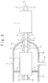
- FIG. 2 shows the structure of the turbine 4 and the generator 7 in the helium turbine power generation system of the present invention.
- the rotation axis 6 passes through the pressure vessel 3 and couples the turbine 4 and the generator 7.
- the turbine 4 is provided in the pressure vessel 3 to be exposed in the helium gas.
- the generator 7 is arranged in the atmosphere outside the pressure vessel 3.
- the rotation axis 6 is composed of rotation axis portions 6-1, 6-2 and 6-3.
- the rotation axis portion 6-1 is rotatably supported by a magnetic bearing 12 in the first portion 3a of the pressure vessel 3, passes through the turbine 4, and is rotatably supported by a magnetic bearing 13 in the second portion 3b of the pressure vessel 3.
- the rotation axis portion 6-2 is rotatably supported by an axis seal device 8 which is fit to the pressure vessel 3.
- the rotation axis portion 6-3 is rotatably supported by an oil bearing 16, passes through the generator 7, and is rotatably supported by an oil bearing 17.
- the rotation axis 6-1 and the rotation axis 6-2 are connected by a diaphragm coupling 14 and the rotation axis 6-2 and the rotation axis 6-3 are connected by a diaphragm coupling 17.
- Fig. 3 shows the structure of the axis seal device 8 of the present invention.
- the axis seal device 8 of the present invention has a first space section 21, a second space section 36 and a third space section 40.
- the first space section 21 is provided as a region defined by the outer circumference surface of the rotation axis 6, a first wall section 21a, and first and second dry gas seals 22 and 32.
- the first dry gas seal 22 is connected to the wall of the pressure vessel 3.
- the second space section 36 is provided as a region defined by the outer circumference surface of the rotation axis 6, a second wall section 36a, the second dry gas seal 32 and a third dry gas seal 39.
- the third space section 40 is provided as a region defined by the outer circumference surface of the rotation axis 6, a third wall section 40a, the third dry gas seal 39 and a labyrinth seal 43.
- the labyrinth seal 43 is connected to a wall which has an opening to the atmosphere.
- the first space section 21 is filled with the helium gas. It is supposed that the gas pressure of the helium gas is P 1 .
- the first pipe 23 passes through the first wall section 21a and is connected with the first space section 21.
- the first space section 21 is connected with a helium supply apparatus 26 by the first pipe 23 through a helium gas buffer tank 24 and a pressure regulating valve 25.
- the helium gas buffer tank 24 is used to change the gas pressure P 1 of the helium gas in the first space section 21 rapidly.
- the pressure regulating valve 25 can be opened or closed in accordance with an open or close instruction from a first controller 31 to be described later.
- the helium supply apparatus 26 has a function to supply the helium gas of high-pressure (P 0 ) much higher than the gas pressure P 1 of the helium gas in the first space section 21 to the first space section 21 when the pressure regulating valve 25 is opened.
- a first pressure sensor 27 is provided in the first space section 21 to measure the pressure P 1 of the helium gas in the first space section 21.
- a second pressure sensor 28 is provided in the second portion 3b of the pressure vessel 3 to measure the pressure (P 2 ) of the helium gas in the second portion 3b.
- the first pressure sensor 27 and the second pressure sensor 28 are connected with a first subtractor 29.
- the first subtractor 29 is connected with a pressure difference setting unit 30.
- the first subtractor 29 subtracts the pressure P 2 measured by the second pressure sensor 28 from the pressure P 1 measured by the first pressure sensor 27, and transmits the pressure difference data indicating the pressure difference (P 1 -P 2 ) to the pressure difference setting unit 30.
- the pressure difference setting unit 30 is connected with the first controller 31.
- the pressure difference setting unit 30 subtracts a predetermined pressure ⁇ ( ⁇ >0) from the pressure difference (P 1 -P 2 ) and transmits the pressure difference data indicating the difference pressure (P 1 -P 2 - ⁇ ) to the first controller 31.
- the first controller 31 controls the open or close of the pressure regulating valve 25 to always satisfy a pressure relation of P 1 > P 2 based on the difference pressure data (P 1 -P 2 - ⁇ ) transmitted from the pressure difference setting unit 30. Therefore, a little volume of helium gas always passes through the first dry gas seal 22 and flows from the first space section 21 into the second portion 3b of the pressure vessel 3. The details of the control of the open and close of the pressure regulating valve 25 by the first controller 31 will be described later.
- the second space section 36 is filled by the helium gas. It is supposed that the gas pressure of the helium gas is P 3 .
- the second space section 36 is connected with the second pipe 33 which passes through the second wall section 36a.
- the second pipe 33 extends from the second space section 36 through a buffer tank 35 for helium gas recirculation and a helium gas recirculation compressor 34, passes through the first wall section 21a and is connected with the first space section 21.
- the buffer tank 35 for helium gas recirculation prevents the rapid change in the gas pressure P 3 of the helium gas in the second space section 36.
- the helium gas recirculation compressor 34 has a function to collect and compress the helium gas in the second space section 36 and the buffer tank 35 for the helium gas recirculation and to supply the compressed helium gas to the first space section 21 through the second pipe 33.
- the helium gas compression operation by the helium gas recirculation compressor 34 is controlled by a second controller 38 connected with the helium gas recirculation compressor 34.
- the second controller 38 is connected with a third pressure sensor 37 provided in the second space section 36 to measure the pressure P 3 of the helium gas in the second space section 36.
- the second controller 38 controls the operation of the helium gas recirculation compressor 34 such that the pressure P 3 measured by the third pressure sensor 37 is lower than the gas pressure P 1 in the first space section 21 and is higher than the atmospheric pressure P a . Therefore, a little volume of helium gas always passes through the second dry gas seal 32 and flows from the first space section 21 to the second space section 36. The details of the control of the operation of the helium gas recirculation compressor 34 by the second controller 38 will be described later.
- the atmosphere exists in a region 44 outside the third space section 40 and the atmospheric pressure is P a .
- the third space section 40 is connected with a third pipe 41 through the third wall section 40a.
- the third pipe 41 connects the third space section 40 with a gas processing apparatus (not shown) through a vacuum suction unit 42.
- the vacuum suction unit 42 has a function to supply gas from the third space section 40 to the gas processing apparatus.
- the vacuum suction unit 42 is controlled by a third controller 46 connected with the vacuum suction unit 42.
- the third controller 46 is connected with a fourth pressure sensor 45 provided to measure the pressure P 4 of the gas in the third space section 40.
- the third controller 46 controls an operation of the vacuum suction unit 42 such that the pressure P 4 measured by the fourth pressure sensor 45 is lower than the gas pressure P 3 in the second space section 36 and the atmospheric pressure P a .
- the details of the control of the operation of the vacuum suction unit 42 by the third controller 46 will be described later.
- the pressure P 4 of gas in third space section 40 is controlled to be lower than the atmospheric pressure P a . Therefore, a little volume of air always passes through the labyrinth seal 43 and flows from the region 44 outside the third space section 40 into the third space section 40. Also, the pressure P 4 in the third space section 40 is controlled to be lower than the gas pressure P 3 in the second space section 36. Therefore, a little volume of helium gas passes through the third dry gas seal 39 and flows from the second space section 36 into the third space section 40. Thus, a mixture gas of the air and the helium gas is in the third space section 40.
- Fig. 4 shows the structure of the first dry gas seal 22.
- the first dry gas seal 22 is composed of a rotation section 51 and a stationary section 52.
- the rotation section 51 is supported on the outer circumference surface of the rotation axis 6.
- the stationary section 52 is supported on the wall of the pressure vessel 3 and the first wall section 21a to be apart from the rotation axis 6.
- the rotation section 51 has a surface section approximately perpendicular to the rotation axis 6 on the side of the stationary section 52.
- a first slide surface section 53 is provided for the surface section of the rotation section 51.
- a spiral ditch is formed on the first slide surface section 53.
- a second slide surface section 54 is a surface section approximately perpendicular to the rotation axis 6, and is provided for the stationary section 52 to contact the above first slide surface section 53.
- the second slide surface section 54 is formed as an approximately flat surface.
- first force acts to the rotation section 51 and the stationary section 52 due to the spiral ditch provided for the first slide surface section 53 such that the first slide surface section 53 and the second slide surface section 54 is separated from each other.
- second force acts to the rotation section 51 and the stationary section 52 such that the first slide surface section 53 and the second slide surface section 54 contact each other, because the rotation section 51 and the stationary section 52 are fixed.
- the gap between the first slide surface section 53 and the second slide surface section 54 is small, a little volume of helium gas passes through the gap. In this case, the helium gas passing through the gap flows from the first space section 21 to the second portion 3b. This is because the gas pressure P 1 of the helium gas in the first space section 21 is adjusted to be higher than the gas pressure P 2 of the helium gas in the second portion 3b by the first controller 31.
- the first dry gas seal 22 can reduce a power loss of the rotation axis 6 because the first slide surface section 53 and the second slide surface section 54 does not contact.
- the first dry gas seal 22 can seal the hot helium gas equal to or higher than 700 °C, because the first dry gas seal 22 does not use lubricating oil.
- the second dry gas seal 32 has the same structure as that of the first dry gas seal 22 except that the stationary section 52 is fixed on the first wall section 21a and the second wall section 36a, similarly to the first dry gas seal 22.
- the function of the second dry gas seal 32 is the same as that of the first dry gas seal 22. Also, when the rotation section 51 is in the rotation state, a small quantity of the helium gas passes through the small gap between the first slide surface section 53 and the second slide surface section 54 and flows from the first space section 21 to the second space section 36. This is because the gas pressure P 1 of the helium gas in the first space section 21 is adjusted to be higher than the gas pressure P 3 of the helium gas in the second space section 36 by the second controller 38.
- the second dry gas seal 32 can reduce a quantity of the helium gas passing through the second dry gas seal 32, like the first dry gas seal 22. Also, the second dry gas seal 32 can reduce a power loss of the rotation axis 6. Moreover, the second dry gas seal 32 can seal the hot gas equal to or higher than 700 °C.
- the third dry gas seal 39 has the same structure as that of the first dry gas seal 22 except that the stationary section 52 is fixed on the second outer wall section 36a and the third wall section 40a, similarly to the first dry gas seal 22.
- the function of the third dry gas seal 39 is the same as that of the first dry gas seal 22. Also, when the rotation section 51 is in the rotation state, a small quantity of the helium gas passes through the small gap produced between the first slide surface section 53 and the second slide surface section 54 and flows from second space section 36 into the third space section 40. This is because the gas pressure P 3 of the helium gas in the second space section 36 is adjusted to be higher than the gas pressure P 4 of gas in the third space section 40 by the third controller 46.
- the third dry gas seal 39 can reduce a quantity of helium gas passing through the third dry gas seal 39, like the first dry gas seal 22. Also, the third dry gas seal 39 can reduce a power loss of the rotation axis 6. Moreover, the third dry gas seal 39 can seal the hot gas equal to or higher than 700 °C .
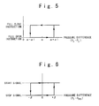
- Fig. 5 is a graph showing relation of the pressure difference data transmitted from the pressure difference setting unit 30 and the control state of the open and close of the pressure regulating valve 25 by the first controller 31.
- the horizontal axis in Fig. 5 indicates the pressure difference (P 1 -P 2 ).
- the vertical axis in Fig. 5 indicates the signal outputted from the first controller 31 to the pressure regulating valve 25. Referring to Fig.
- the first controller 31 transmits a full open instruction signal to the pressure regulating valve 25 such that the pressure regulating valve 25 is fully opened.
- the helium gas with the pressure P 0 (P 0 >> P 1 ) is supplied from the helium supply apparatus 26 to the first space section 21 through the helium gas buffer tank 24.
- the pressure of ⁇ 1 is preset by the first controller 31.
- the pressure P 1 of the helium gas in the first space section 21 rises.
- the first controller 31 transmits a full close instruction signal to the pressure regulating valve 25 such that the pressure regulating valve 25 is fully closed. As such, the supply of the helium gas from the helium supply apparatus 26 to the first space section 21 is stopped.
- the first controller 31 controls the pressure regulating valve 25 to keep a state in which the gas pressure P 1 in the first space section 21 is higher than the gas pressure P 2 in the second portion 3b of the pressure vessel 3. Also, the first controller 31 controls the pressure regulating valve 25 such that the gas pressure P 1 in the first space section 21 does not become higher by a constant value than the gas pressure P 2 in the second portion 3b of the pressure vessel 3.
- a spare power (not shown) is connected with the pressure regulating valve 25.
- the first controller 31 controls the pressure regulating valve 25 to be fully opened so as not for helium gas to leak from the second portion 3b of the pressure vessel 3.
- Fig. 6 is a graph showing relation of the pressure P 3 measured by the third pressure sensor 37 and the control state of the helium gas recirculation compressor 34 by the second controller 38.
- the horizontal axis of Fig. 6 shows pressure difference (P 3 -P STD ).
- the pressure P STD is a reference pressure value preset by the second controller 38 and always satisfies the relation of P 4 ⁇ P STD ⁇ P 1 and the relation of
- the vertical axis of Fig. 6 shows the state of the control signal outputted from the second controller 38 to the helium gas recirculation compressor 34.
- the second controller 38 when the pressure difference (P 3 -P STD ) between the pressure P 3 measured by the third pressure sensor 37 and the pressure P STD is lower than the pressure of - ⁇ (P 4 ⁇ P STD - ⁇ ⁇ P STD + ⁇ ⁇ P 1 ), the second controller 38 outputs a stop signal to the helium gas recirculation compressor 34.
- the pressure ⁇ is preset by the second controller 38.
- the helium gas recirculation compressor 34 stops the operation in response to the stop signal. In the case, a little quantity of the helium gas is supplied from the first space section 21 to the second space section 36 through the second dry gas seal 32.
- the pressure of P STD is selected to always satisfy the relation of
- the second controller 38 outputs an operation start signal to the helium gas recirculation compressor 34.
- the helium gas recirculation compressor 34 starts the operation in response to the operation start signal. In this case, because the helium gas recirculation compressor 34 collects the helium gas in the second space section 36, the gas pressure P 3 in the second space section 36 decreases.
- the second controller 38 outputs the stop signal to stop the operation of the helium gas recirculation compressor 34 again.
- the second controller 38 controls the operation of the helium gas recirculation compressor 34 to keep a state in which the gas pressure P 3 in the second space section 36 is lower than the gas pressure P 1 in the first space section 21 and is higher than the gas pressure P4 in the third space section 40.
- the helium gas recirculation compressor 34 and the second controller 38 are connected with a spare power (not shown), such that the helium gas recirculation compressor 34 and the second controller 38 can operate, even when the supply of the power to the helium gas recirculation compressor 34 and the second controller 38 is cut down.
- Fig. 7 is the graph showing a relation of the pressure P 4 measured by fourth pressure sensor 45 and the control state of the vacuum suction unit 42 by the third controller 46 in the first example of the control operation of the vacuum suction unit 42 by the third controller 46.
- the horizontal axis of Fig. 7 shows pressure difference (P 4 -P STD2 ).
- the pressure P STD2 is a reference pressure value preset by the third controller 46 and fills within the range of 0 ⁇ P STD2 ⁇ P a (P a is atmospheric pressure).
- the vertical axis of Fig. 7 shows the number of rotations of the vacuum suction unit 42, i.e., an exhausted gas quantity.
- the vacuum suction unit 42 has a function to supply gas in the third space section 40 to the gas processing unit (not shown).
- the vacuum suction unit 42 increases the supply quantity of gas in the third space section 40 to the gas processing unit.
- the vacuum suction unit 42 decreases the supply quantity of gas in the third space section 40 to the gas processing unit.
- the third controller 46 increases the number of rotations of the vacuum suction unit 42.
- the pressure ⁇ 1 is preset by the third controller 46.
- the third controller 46 sets the increment of the number of rotations continuously to be approximately proportional to the pressure (P 4 -P STD2 - ⁇ 1 ).
- the third controller 46 decreases the number of rotations of the vacuum suction unit 42.
- the pressure ⁇ 2 is preset by the third controller 46.
- the third controller 46 sets the decrement of the number of rotations continuously to be approximately proportional to pressure (P 4 -P STD2 + ⁇ 2 ).
- the vacuum suction unit 42 and the third controller 46 is connected with a spare power (not shown) the vacuum suction unit 42 and the third controller 46 can operate even when the supply of the power is cut off to the vacuum suction unit 42 and the third controller 46.
- Fig. 8 is a graph showing a relation of the pressure P4 measured by the fourth pressure sensor 45 and the control state of the vacuum suction unit 42 by the third controller 46 in the second embodiment of the control operation of the vacuum suction unit 42 by the third controller 46.
- the horizontal axis of Fig. 8 shows pressure difference (P 4 -P STD2 ).
- the pressure P STD2 is a reference pressure value preset by the third controller 46 and fills within a range of 0 ⁇ P STD2 ⁇ P a (P a is atmospheric pressure).
- the vertical axis of Fig. 8 shows the number of rotations of the vacuum suction unit 42.
- the structure and function of the vacuum suction unit 42 are the same as those of the vacuum suction unit 42 in the first example of the control action shown in the above.
- the third controller 46 controls to increase the number of rotations of the vacuum suction unit 42 to R 1 (R 1 >R 0 ).
- the pressure ⁇ 3 is preset by the third controller 46.
- the number of rotations R 1 is preset by the third controller 46.
- the third controller 46 returns the number of rotations of the vacuum suction unit 42 to R 0 .
- the pressure ⁇ 4 is preset by the third controller 46.
- the third controller 46 decreases the number of rotations of the vacuum suction unit 42 to R 2 (R 2 ⁇ R 0 ).
- the pressure ⁇ 5 is preset by the third controller 46.
- the number of rotations R 2 is preset by the third controller 46.
- the third controller 46 returns the number of rotations of the vacuum suction unit 42 to R 0 .
- the pressure ⁇ 6 is preset by the third controller 46.
- a spare power (not shown) is connected with the vacuum suction unit 42 and the third controller 46 such that the vacuum suction unit 42 and the third controller 46 can operate even when the supply of the power is cut off to the vacuum suction unit 42 and the third controller 46.
- the axis seal device it is possible to further include M space sections (M is an integer satisfying M ⁇ 1) connected with the second space section 36 through the dry gas seal.
- M is an integer satisfying M ⁇ 1
- the space sections adjacent to each other are sealed by the dry gas seal, and each of the space sections is a region defined by the outer wall section like the second outer wall section 36a and the rotation axis 6.
- the structure and function of the dry gas seal are the same as the first dry gas seal 22.
- the first space section is provided adjacent to the second section 3b in the direction of the axis direction 6a.
- the (L+1)-th space section is provided adjacent to the L-th (L is an integer satisfying 1 ⁇ L ⁇ M) space section into the direction of the axis direction 6a.
- the third space section 40 is provided adjacent to the M-th space section in the direction of the axis direction 6a.
- the L-th space section is connected with the pipe which passes through an outer wall section like the second space section 36.
- the pipe is connected from the L-th space section to the (L-1)-th space section through a L-th buffer tank for the helium gas recirculation and the L-th helium gas recirculation compressor.
- the pipe is connected from the L-th space section to the second space section through the first buffer tank for the helium gas recirculation and the first helium gas recirculation compressor.
- the structure and function of the L-th buffer tank for the helium gas recirculation are the same as those of the buffer tank 35 for the helium gas recirculation connected with the second space section 36.
- the structure and function of the L-th helium gas recirculation compressor are the same as those of the helium gas recirculation compressor 34 connected with the second space section 36.
- the L-th pressure sensor is provided in the L-th space section to measure the gas pressure of the L-th space section.
- the L-th pressure sensor is connected with a L-th controller to control the operation of the helium gas recirculation compressor.
- the function of the L-th controller is the same as that of the second controller 38 excluding that the pressure P STD as the reference pressure value preset by the second controller 38 is different. Supposing that the reference pressure value preset by the L-th controller is P STD(L) , P STD(L) is set to satisfy the relation of P STD(L-1) - ⁇ > P STD(L) + ⁇ in case of 2 ⁇ L ⁇ M .
- the pressure P STD(1) is set to satisfy the relation of P STD - ⁇ > P STD(1) + ⁇ .
- the pressure P STD(M) is set to satisfy P STD(M-1) - ⁇ > P STD(M) + ⁇ and P STD(M) - ⁇ > P STD2 .
- the pressure ⁇ is preset by the L-th controller and the second controller 38.
- the pressure P STD2 is the reference pressure value preset by the third controller 46.
- the gas pressure in the L-th space section is controlled to be always lower than the gas pressure in the (L-1)-th space section.
- a little quantity of gas flows from the (L-1)-th space section to the L-th space section at the dry gas seal sealing between the L-th space section and the (L-1)-th space section, when the rotation axis 6 is in the rotation state.
- These M space sections permit a little quantity of helium gas to flow from the second space section 36 to the third space section 40, but prevent gas from flowing from the third space section 40 to the second space section 36, when the rotation axis 6 is in the rotation state.
- the turbine is arranged in the pressure vessel and the power generator is arranged outside the pressure vessel by using an axis seal device. Therefore, in the helium gas turbine power generation system of the present invention, the pressure vessel can be made small by the size of the generator, compared with a conventional example.
- the maintenance process of the helium gas turbine power generation system of the pressure vessel can be reduced.
- the axis seal device of the present invention when the turbine is arranged in the pressure vessel and the generator is arranged outside the pressure vessel in the relatively large-scaled helium gas turbine power generation system, it is possible to seal the rotation axis portion between the turbine and the generator such that the helium gas circulating in the pressure vessel does not leak out outside the pressure vessel.
Landscapes
- Engineering & Computer Science (AREA)
- General Engineering & Computer Science (AREA)
- Mechanical Engineering (AREA)
- Sealing Using Fluids, Sealing Without Contact, And Removal Of Oil (AREA)
Abstract
An axis seal device (8) is provided between a vessel (3) filled with
a first gas of a first gas pressure and a rotation axis (6) passing
through the vessel (3). The axis seal device (8) includes first (22) to
third (39) dry gas seal sections. The first dry gas seal section (22) is
provided such that the rotation axis (6) is rotatable, and has a first
space (21) section with a second gas pressure. The second dry gas seal
section (32) is provided subsequently to the first dry gas seal section
(22) such that the rotation axis (6) is rotatable, and has a second
space section (36) with a third gas pressure. The third dry gas seal
section (39) is provided subsequently to the second dry gas seal section
(32) such that the rotation axis (6) is rotatable, and has a third space
section (40) with a fourth gas pressure. The first gas pressure is lower
than the second gas pressure, the second gas pressure is higher than the
third gas pressure, the third gas pressure is higher than the fourth gas
pressure and an atmospheric pressure, and the fourth gas pressure is
lower than the atmospheric pressure.
Description
The present invention relates to a rotation
axis seal device and a helium gas turbine power
generation system, which uses the shaft seal device
and generates electric power by rotating a gas turbine
using helium gas.
As one of atomic generation systems, a helium
gas turbine power generation system is developed. In
the helium gas turbine power generation system, helium
gas is used as a primary system gas supplied from a
high temperature gas reactor like a nuclear reactor,
and a gas turbine is rotated with the helium gas to
generate electric power.
In such a helium gas turbine power generation
system, it is necessary that the primary system helium
gas does not leak out outside. Therefore, in a
conventional helium gas turbine power generation
system, a gas turbine and a generator are accommodated
in a pressure vessel in which the primary system
helium gas is circulated. Because the pressure vessel
is radioactively polluted with the primary system
helium gas, a lot of processes are needed for the
maintenance of the pressure vessel.
Generally, it is desired to make a gas
turbine and a generator large in size for the high
efficiency of power generation. However, if the gas
turbine and the generator are made large in size, a
large pressure vessel is needed, and more processes
are needed for the maintenance of the pressure vessel.
Therefore, an object of the present invention
is to provide a helium gas turbine power generation
system, in which a pressure vessel can be made small
in size.
Another object of the present invention is to
provide a helium gas turbine power generation system
in which a turbine is arranged in a pressure vessel
and a generator is arranged outside the pressure
vessel.
Still another object of the present invention
is to provide a rotation axis seal device which can
prevent the leakage of gas in a rotary shaft.
In an aspect of the present invention, an
axis seal device is provided between a vessel filled
with a first gas of a first gas pressure and a
rotation axis as a rotary shaft which passes through
the vessel. The axis seal device includes first to
third dry gas seal sections. The first dry gas seal
section is provided between the rotation axis and the
vessel such that the rotation axis is rotatable, and
has a first space section with a second gas pressure.
The second dry gas seal section is provided
subsequently to the first dry gas seal section between
the rotation axis and the vessel such that the
rotation axis is rotatable, and has a second space
section with a third gas pressure. The third dry gas
seal section is provided subsequently to the second
dry gas seal section between the rotation axis and the
vessel such that the rotation axis is rotatable, and
has a third space section with a fourth gas pressure.
The first gas pressure is lower than the second gas
pressure, the second gas pressure is higher than the
third gas pressure, the third gas pressure is higher
than the fourth gas pressure and an atmospheric
pressure, and the fourth gas pressure is lower than
the atmospheric pressure.
The first dry gas seal section may include a
first gas pressure control section which controls the
second gas pressure such that the second gas pressure
is higher than the first gas pressure. In this case,
the first gas pressure control section may include a
first pressure sensor provided in the vessel to sense
the first gas pressure; a second pressure sensor
provided in the first space section to sense the
second gas pressure; a gas supply unit which supplies
gas of a gas pressure higher than the second gas
pressure into the first space section; and a valve
connected with the first space section and the gas
supply unit. A first control section controls the
valve for the gas supply unit to supply the gas into
the first space section based on the first gas
pressure sensed by the first pressure sensor and the
second gas pressure sensed by the second pressure
sensor such that the second gas pressure is higher
than the first gas pressure. The first control
section controls the valve based on the first gas
pressure sensed by the first pressure sensor and the
second gas pressure sensed by the second pressure
sensor for the gas supply unit to supply the gas into
the first space section to have a hysteresis
characteristic in a predetermined first range.
Also, the first space section may defined by
the rotation axis, a wall of the axis seal device, a
first dry gas seal and a second dry gas seal, and the
first dry gas seal is opened to an inside of the
vessel, and the second dry gas seal is shared by the
second space section.
Also, the third dry gas seal section may
include a third gas pressure control section which
controls the fourth gas pressure such that the fourth
gas pressure is lower than the third gas pressure and
the atmospheric pressure. In this case, the third gas
pressure control section may include a fourth pressure
sensor provided in the third space section to sense
the fourth gas pressure; and a gas exhausting unit
connected the third second space section. A third
control section controls the gas exhausting unit based
on the fourth gas pressure sensed by the fourth
pressure sensor such that the fourth gas pressure is
lower than the third gas pressure and the atmospheric
pressure. In this case, the third control section
controls the gas exhausting unit to have a hysteresis
characteristic in a predetermined third range based on
the fourth gas pressure sensed by the fourth pressure
sensor such that the fourth gas pressure is lower than
the third gas pressure and the atmospheric pressure.
Also, the third space section may be defined
by the rotation axis, a wall of the axis seal device,
a third dry gas seal and a labyrinth seal, and the
labyrinth seal is opened to atmosphere, and the third
dry gas seal is shared by the second space section.
Also, the second dry gas seal section may
include a second gas pressure control section which
controls the third gas pressure such that the third
gas pressure is lower than the second gas pressure and
higher than the atmospheric pressure. At this time,
the second gas pressure control section may include a
third pressure sensor provided in the second space
section to sense the third gas pressure; and a gas
recirculation unit which recirculates gas from the
second space section into the first space section. A
second control section controls the gas recirculation
unit based on the third gas pressure sensed by the
third pressure sensor such that the third gas pressure
is lower than the second gas pressure and higher than
the atmospheric pressure. In this case, the second
control section controls the gas recirculation unit to
have a hysteresis characteristic in a predetermined
second range based on the third gas pressure sensed by
the third pressure sensor such that the third gas
pressure is lower than the second gas pressure and
always higher than the atmospheric pressure.
Also, the second space section may be defined
by the rotation axis, a wall of the axis seal device,
a second dry gas seal and a third dry gas seal, and
the second dry gas seal is shared by the first space
section and the third dry gas seal is shared by the
third space section.
Also, the second dry gas seal section may
include N dry gas seal subsections (N is an integer
more than 1) connected in series, and the second space
section may include N space subsections. An M-th(2≦M
≦N) one of the N dry gas seal subsections may
include: a M-th space subsection; and a second gas
pressure control section which controls an M-th gas
pressure of the M-th space subsection such that the M-th
gas pressure of the M-th space subsection is lower
than an (M-1)-th gas pressure of an (M-1)-th space
subsection and higher than an (M+1)-th gas pressure of
an (M+1)-th space subsection and the atmospheric
pressure. At this time, the M-th gas pressure control
section may include: a M-th pressure sensor provided
in the M-th space subsection to sense the M-th gas
pressure; and a M-th gas recirculation unit which
recirculates gas from the M-th space subsection into
the (M-1)-th space subsection. An M-th control
section controls the M-th gas recirculation unit based
on the M-th gas pressure sensed by the M-th pressure
sensor such that the M-th gas pressure of the M-th
space subsection is lower than an (M-1)-th gas
pressure of an (M-1)-th space subsection and higher
than an (M+1)-th gas pressure of an (M+1)-th space
subsection and the atmospheric pressure. In this case,
the M-th control section controls the M-th gas
recirculation unit to have a hysteresis characteristic
in a predetermined range based on the M-th gas
pressure sensed by the M-th pressure sensor such that
the M-th gas pressure of the M-th space subsection is
lower than an (M-1)-th gas pressure of an (M-1)-th
space subsection and higher than an (M+1)-th gas
pressure of an (M+1)-th space subsection and the
atmospheric pressure.
Also, the M-th space subsection may be
defined by the rotation axis, a wall of the axis seal
device, an (M-1)-th dry gas seal and an M-th dry gas
seal, and the (M-1)-th dry gas seal is shared by the
(M-1)-th space subsection and the M-th dry gas seal is
shared by the (M+1)-th space section.
In the above, the gas may be a helium gas,
and is in a temperature range of 700 °C to 1000 °C.
In another aspect of the present invention, a
gas turbine power generation system may include: a gas
reactor which heats up the gas to produce a hot gas;
the vessel connected to the gas reactor; a turbine
accommodated in the vessel and rotated by the hot gas;
a separator member provided for the vessel and the
turbine to separate an inside of the vessel into first
and second portions; a power generator provided
outside the vessel and connected to the turbine by the
rotation axis; and the axis seal device described
above, provided between the rotation axis and the
vessel.
In this case, the gas turbine power
generation system may further include a circulating
unit which circulates the hot gas from the second
portion into the first portion.
Also, in still another aspect of the present
invention, a method of sealing between a first portion
filled with a gas and a second portion in atmosphere,
is achieved by providing first to third space sections
between the first portion and the second portion; by
controlling a second gas pressure in the first space
section to be higher than a first gas pressure in a
first portion; by controlling a third gas pressure in
the second space section to be lower than a fourth gas
pressure in the third space section and to be higher
than an atmospheric pressure; and by controlling the
fourth gas pressure to be lower than the atmospheric
pressure.
In this case, a first dry gas seal is
provided between the first portion and the first space
section, a second dry gas seal is provided between the
first space section and the second space section, and
a third dry gas seal is provided between the second
space section and the third space section.
Hereinafter, the helium turbine power
generation system of the present invention will be
described with reference to the attached drawings.
Fig. 1 is a schematic diagram showing the
structure of the helium gas turbine power generation
system of the present invention. Referring to Fig. 1,
the helium gas turbine power generation system of the
present invention contains a high temperature gas
reactor 1 which supplies hot helium gas in a
temperature range of 700 °C to 1,000 °C to a pressure
vessel 3 through a pipe 2.
The turbine 4 is accommodated in the pressure
vessel 3. A separation member 5 is provided to
separate the internal space of the pressure vessel 3
around the turbine 4 into a first portion 3a as an
inner circumference section and a second portion 3b as
an outer circumference section. The first portion 3a
is connected with the pipe 2, but the second portion
3b is not connected with the pipe 2. Therefore, the
helium gas is supplied from the high temperature gas
reactor 1 to the first portion 3a through the pipe 2,
passes through the turbine 4 and then is supplied to
the second portion 3b. In this way, the turbine 4
with turbine blades (not shown) is rotated with the
hot helium gas supplied from the high temperature gas
reactor 1 into the turbine 4.
Also, the turbine 4 is connected with a
generator 7 by a rotation axis 6 as a rotary shaft.
The generator 7 is arranged outside the pressure
vessel 3, and the rotation axis 6 penetrates the wall
of the pressure vessel 3. An axis seal device 8 is
provided between the pressure vessel 3 and the
rotation axis 6. The axis seal device 8 does not
prevent the rotation of the rotation axis 6 and has a
function to prevent the helium gas circulating in the
pressure vessel 3 from leaking out from the pressure
vessel 3. The structures of the rotation axis 6 and
axis seal device 8 will be described later in detailed.
Moreover, the helium turbine power generation
system is further composed of a pipe 9 for connecting
the first portion 3a and a heat exchanger 11, and a
pipe 10 for connecting the second portion 3b and the
heat exchanger 11. The heat exchanger 11 acquires the
helium gas supplied to the second portion 3b through
the pipe 10 and cools the helium gas, and then
supplies it to a pressurizing section (not shown).
The helium gas pressurized by the pressurizing section
(not shown) is supplied to the first portion 3a
through the pipe 9.
Next, the rotation axis 6 will be described
in detail. Fig. 2 shows the structure of the turbine
4 and the generator 7 in the helium turbine power
generation system of the present invention. Referring
to Fig. 2, the rotation axis 6 passes through the
pressure vessel 3 and couples the turbine 4 and the
generator 7. The turbine 4 is provided in the
pressure vessel 3 to be exposed in the helium gas.
The generator 7 is arranged in the atmosphere outside
the pressure vessel 3.
The rotation axis 6 is composed of rotation
axis portions 6-1, 6-2 and 6-3. The rotation axis
portion 6-1 is rotatably supported by a magnetic
bearing 12 in the first portion 3a of the pressure
vessel 3, passes through the turbine 4, and is
rotatably supported by a magnetic bearing 13 in the
second portion 3b of the pressure vessel 3. The
rotation axis portion 6-2 is rotatably supported by an
axis seal device 8 which is fit to the pressure vessel
3. The rotation axis portion 6-3 is rotatably
supported by an oil bearing 16, passes through the
generator 7, and is rotatably supported by an oil
bearing 17. The rotation axis 6-1 and the rotation
axis 6-2 are connected by a diaphragm coupling 14 and
the rotation axis 6-2 and the rotation axis 6-3 are
connected by a diaphragm coupling 17.
Next, the axis seal device 8 will be
described in detail. Fig. 3 shows the structure of
the axis seal device 8 of the present invention.
Referring to Fig. 3, the axis seal device 8 of the
present invention has a first space section 21, a
second space section 36 and a third space section 40.
The first space section 21 is provided as a
region defined by the outer circumference surface of
the rotation axis 6, a first wall section 21a, and
first and second dry gas seals 22 and 32. The first
dry gas seal 22 is connected to the wall of the
pressure vessel 3. The second space section 36 is
provided as a region defined by the outer
circumference surface of the rotation axis 6, a second
wall section 36a, the second dry gas seal 32 and a
third dry gas seal 39. The third space section 40 is
provided as a region defined by the outer
circumference surface of the rotation axis 6, a third
wall section 40a, the third dry gas seal 39 and a
labyrinth seal 43. The labyrinth seal 43 is connected
to a wall which has an opening to the atmosphere.
The first space section 21 is filled with the
helium gas. It is supposed that the gas pressure of
the helium gas is P1. The first pipe 23 passes through
the first wall section 21a and is connected with the
first space section 21. Thus, the first space section
21 is connected with a helium supply apparatus 26 by
the first pipe 23 through a helium gas buffer tank 24
and a pressure regulating valve 25. The helium gas
buffer tank 24 is used to change the gas pressure P1
of the helium gas in the first space section 21
rapidly. The pressure regulating valve 25 can be
opened or closed in accordance with an open or close
instruction from a first controller 31 to be described
later. The helium supply apparatus 26 has a function
to supply the helium gas of high-pressure (P0) much
higher than the gas pressure P1 of the helium gas in
the first space section 21 to the first space section
21 when the pressure regulating valve 25 is opened.
Also, a first pressure sensor 27 is provided
in the first space section 21 to measure the pressure
P1 of the helium gas in the first space section 21.
Moreover, a second pressure sensor 28 is provided in
the second portion 3b of the pressure vessel 3 to
measure the pressure (P2) of the helium gas in the
second portion 3b. The first pressure sensor 27 and
the second pressure sensor 28 are connected with a
first subtractor 29. The first subtractor 29 is
connected with a pressure difference setting unit 30.
The first subtractor 29 subtracts the pressure P2
measured by the second pressure sensor 28 from the
pressure P1 measured by the first pressure sensor 27,
and transmits the pressure difference data indicating
the pressure difference (P1-P2) to the pressure
difference setting unit 30. The pressure difference
setting unit 30 is connected with the first controller
31. The pressure difference setting unit 30 subtracts
a predetermined pressure α (α>0) from the pressure
difference (P1-P2) and transmits the pressure
difference data indicating the difference pressure
(P1-P2-α) to the first controller 31. The first
controller 31 controls the open or close of the
pressure regulating valve 25 to always satisfy a
pressure relation of P1 > P2 based on the difference
pressure data (P1-P2-α) transmitted from the pressure
difference setting unit 30. Therefore, a little
volume of helium gas always passes through the first
dry gas seal 22 and flows from the first space section
21 into the second portion 3b of the pressure vessel 3.
The details of the control of the open and close of
the pressure regulating valve 25 by the first
controller 31 will be described later.
Also, the second space section 36 is filled
by the helium gas. It is supposed that the gas
pressure of the helium gas is P3. The second space
section 36 is connected with the second pipe 33 which
passes through the second wall section 36a. The
second pipe 33 extends from the second space section
36 through a buffer tank 35 for helium gas
recirculation and a helium gas recirculation
compressor 34, passes through the first wall section
21a and is connected with the first space section 21.
The buffer tank 35 for helium gas recirculation
prevents the rapid change in the gas pressure P3 of
the helium gas in the second space section 36. Also,
the helium gas recirculation compressor 34 has a
function to collect and compress the helium gas in the
second space section 36 and the buffer tank 35 for the
helium gas recirculation and to supply the compressed
helium gas to the first space section 21 through the
second pipe 33. The helium gas compression operation
by the helium gas recirculation compressor 34 is
controlled by a second controller 38 connected with
the helium gas recirculation compressor 34. The
second controller 38 is connected with a third
pressure sensor 37 provided in the second space
section 36 to measure the pressure P3 of the helium
gas in the second space section 36. The second
controller 38 controls the operation of the helium gas
recirculation compressor 34 such that the pressure P3
measured by the third pressure sensor 37 is lower than
the gas pressure P1 in the first space section 21 and
is higher than the atmospheric pressure Pa. Therefore,
a little volume of helium gas always passes through
the second dry gas seal 32 and flows from the first
space section 21 to the second space section 36. The
details of the control of the operation of the helium
gas recirculation compressor 34 by the second
controller 38 will be described later.
Also, the atmosphere exists in a region 44
outside the third space section 40 and the atmospheric
pressure is Pa. The third space section 40 is
connected with a third pipe 41 through the third wall
section 40a. The third pipe 41 connects the third
space section 40 with a gas processing apparatus (not
shown) through a vacuum suction unit 42. The vacuum
suction unit 42 has a function to supply gas from the
third space section 40 to the gas processing apparatus.
The vacuum suction unit 42 is controlled by a third
controller 46 connected with the vacuum suction unit
42. The third controller 46 is connected with a
fourth pressure sensor 45 provided to measure the
pressure P4 of the gas in the third space section 40.
The third controller 46 controls an operation of the
vacuum suction unit 42 such that the pressure P4
measured by the fourth pressure sensor 45 is lower
than the gas pressure P3 in the second space section
36 and the atmospheric pressure Pa. The details of the
control of the operation of the vacuum suction unit 42
by the third controller 46 will be described later.
As described above, the pressure P4 of gas in
third space section 40 is controlled to be lower than
the atmospheric pressure Pa. Therefore, a little
volume of air always passes through the labyrinth seal
43 and flows from the region 44 outside the third
space section 40 into the third space section 40.
Also, the pressure P4 in the third space section 40 is
controlled to be lower than the gas pressure P3 in the
second space section 36. Therefore, a little volume
of helium gas passes through the third dry gas seal 39
and flows from the second space section 36 into the
third space section 40. Thus, a mixture gas of the
air and the helium gas is in the third space section
40.
The structure and function of the first dry
gas seal 22 will be described below.
Fig. 4 shows the structure of the first dry
gas seal 22. Referring to Fig. 4, the first dry gas
seal 22 is composed of a rotation section 51 and a
stationary section 52. The rotation section 51 is
supported on the outer circumference surface of the
rotation axis 6. The stationary section 52 is
supported on the wall of the pressure vessel 3 and the
first wall section 21a to be apart from the rotation
axis 6. The rotation section 51 has a surface section
approximately perpendicular to the rotation axis 6 on
the side of the stationary section 52. A first slide
surface section 53 is provided for the surface section
of the rotation section 51. A spiral ditch is formed
on the first slide surface section 53. Also, a second
slide surface section 54 is a surface section
approximately perpendicular to the rotation axis 6,
and is provided for the stationary section 52 to
contact the above first slide surface section 53. The
second slide surface section 54 is formed as an
approximately flat surface.
Next, the function of the first dry gas seal
22 will be described.
First, when the rotation section 51 is in a
stationary state, the first slide surface section 53
and the second slide surface section 54 fit to each
other. In this case, any the helium gas cannot pass
through between the first slide surface section 53 and
the second slide surface section 54.
Next, when rotation section 51 is in a
rotation state, first force acts to the rotation
section 51 and the stationary section 52 due to the
spiral ditch provided for the first slide surface
section 53 such that the first slide surface section
53 and the second slide surface section 54 is
separated from each other. Also, at the same time,
second force acts to the rotation section 51 and the
stationary section 52 such that the first slide
surface section 53 and the second slide surface
section 54 contact each other, because the rotation
section 51 and the stationary section 52 are fixed.
With the balance between the first force and the
second force, it is possible to form a small gap
between the first slide surface section 53 and the
second slide surface section 54. As a result, the
stationary section 52 does not prevent the rotation of
the rotation section 51. Moreover, because the gap
between the first slide surface section 53 and the
second slide surface section 54 is small, a little
volume of helium gas passes through the gap. In this
case, the helium gas passing through the gap flows
from the first space section 21 to the second portion
3b. This is because the gas pressure P1 of the helium
gas in the first space section 21 is adjusted to be
higher than the gas pressure P2 of the helium gas in
the second portion 3b by the first controller 31.
As described above, when the rotation section
51 is in the rotation state, it is possible to reduce
a quantity of helium gas passing through the first dry
gas seal 22 because the gap between the first slide
surface section 53 and the second slide surface
section 54 is small. Also, the first dry gas seal 22
can reduce a power loss of the rotation axis 6 because
the first slide surface section 53 and the second
slide surface section 54 does not contact. Moreover,
the first dry gas seal 22 can seal the hot helium gas
equal to or higher than 700 °C, because the first dry
gas seal 22 does not use lubricating oil.
Next, the structure and function of the
second dry gas seal 32 will be described. The second
dry gas seal 32 has the same structure as that of the
first dry gas seal 22 except that the stationary
section 52 is fixed on the first wall section 21a and
the second wall section 36a, similarly to the first
dry gas seal 22.
Next, the function of the second dry gas seal
32 will be described. The function of the second dry
gas seal 32 is the same as that of the first dry gas
seal 22. Also, when the rotation section 51 is in the
rotation state, a small quantity of the helium gas
passes through the small gap between the first slide
surface section 53 and the second slide surface
section 54 and flows from the first space section 21
to the second space section 36. This is because the
gas pressure P1 of the helium gas in the first space
section 21 is adjusted to be higher than the gas
pressure P3 of the helium gas in the second space
section 36 by the second controller 38.
As described above, the second dry gas seal
32 can reduce a quantity of the helium gas passing
through the second dry gas seal 32, like the first dry
gas seal 22. Also, the second dry gas seal 32 can
reduce a power loss of the rotation axis 6. Moreover,
the second dry gas seal 32 can seal the hot gas equal
to or higher than 700 °C.
Next, the structure and function of the third
dry gas seal 39 will be described. The third dry gas
seal 39 has the same structure as that of the first
dry gas seal 22 except that the stationary section 52
is fixed on the second outer wall section 36a and the
third wall section 40a, similarly to the first dry gas
seal 22.
Next, the function of the third dry gas seal
39 will be described. The function of the third dry
gas seal 39 is the same as that of the first dry gas
seal 22. Also, when the rotation section 51 is in the
rotation state, a small quantity of the helium gas
passes through the small gap produced between the
first slide surface section 53 and the second slide
surface section 54 and flows from second space section
36 into the third space section 40. This is because
the gas pressure P3 of the helium gas in the second
space section 36 is adjusted to be higher than the gas
pressure P4 of gas in the third space section 40 by
the third controller 46.
As described above, the third dry gas seal 39
can reduce a quantity of helium gas passing through
the third dry gas seal 39, like the first dry gas seal
22. Also, the third dry gas seal 39 can reduce a
power loss of the rotation axis 6. Moreover, the
third dry gas seal 39 can seal the hot gas equal to or
higher than 700 °C .
Next, the open and close control operation of
the pressure regulating valve 25 by the first
controller 31 will be described.
Fig. 5 is a graph showing relation of the
pressure difference data transmitted from the pressure
difference setting unit 30 and the control state of
the open and close of the pressure regulating valve 25
by the first controller 31. Here, the horizontal axis
in Fig. 5 indicates the pressure difference (P1-P2).
Also, the vertical axis in Fig. 5 indicates the signal
outputted from the first controller 31 to the pressure
regulating valve 25. Referring to Fig. 5, first, when
the pressure difference data is transmitted from the
pressure difference setting unit 30 to the first
controller 31 to indicate that the pressure difference
of (P1-P2-α) is lower than the pressure of - α1 (0<α1<
α), the first controller 31 transmits a full open
instruction signal to the pressure regulating valve 25
such that the pressure regulating valve 25 is fully
opened. The helium gas with the pressure P0 (P0 >> P1)
is supplied from the helium supply apparatus 26 to the
first space section 21 through the helium gas buffer
tank 24. Here, the pressure of α1 is preset by the
first controller 31.
Next, if the helium gas with the pressure P0
(P0 >> P1) continues to be supplied from the helium
supply apparatus 26 to the first space section 21, the
pressure P1 of the helium gas in the first space
section 21 rises. In this case, when the pressure
difference data is transmitted from the pressure
difference setting unit 30 to the first controller 31
to indicate that the pressure difference (P1-P2-α) is
equal to or higher than pressure of α1, the first
controller 31 transmits a full close instruction
signal to the pressure regulating valve 25 such that
the pressure regulating valve 25 is fully closed. As
such, the supply of the helium gas from the helium
supply apparatus 26 to the first space section 21 is
stopped.
Next, when the supply of the helium gas from
the helium supply apparatus 26 to the first space
section 21 is stopped, a little quantity of helium gas
in the first space section 21 leaks out through the
first dry gas seal 22 and second dry gas seal 32.
Therefore, the gas pressure P1 of the helium gas in
the first space section 21 decreases gradually. In
this case, when the pressure difference data is
transmitted from the pressure difference setting unit
30 to the first controller 31 to indicate that the
pressure difference of (P1-P2-α) is lower than the
pressure of -α1, the first controller 31 transmits the
full open instruction signal to the pressure
regulating valve 25 such that the pressure regulating
valve 25 is fully opened again.
As described above, the first controller 31
controls the pressure regulating valve 25 to keep a
state in which the gas pressure P1 in the first space
section 21 is higher than the gas pressure P2 in the
second portion 3b of the pressure vessel 3. Also, the
first controller 31 controls the pressure regulating
valve 25 such that the gas pressure P1 in the first
space section 21 does not become higher by a constant
value than the gas pressure P2 in the second portion
3b of the pressure vessel 3.
In this case, it is desirable that a spare
power (not shown) is connected with the pressure
regulating valve 25. When the supply of the power for
driving the pressure regulating valve 25 is stopped,
the first controller 31 controls the pressure
regulating valve 25 to be fully opened so as not for
helium gas to leak from the second portion 3b of the
pressure vessel 3.
Next, the control operation of the helium gas
recirculation compressor 34 by the second controller
38 will be described. Fig. 6 is a graph showing
relation of the pressure P3 measured by the third
pressure sensor 37 and the control state of the helium
gas recirculation compressor 34 by the second
controller 38. Here, the horizontal axis of Fig. 6
shows pressure difference (P3-PSTD). The pressure PSTD
is a reference pressure value preset by the second
controller 38 and always satisfies the relation of P4
< PSTD < P1 and the relation of |P1-PSTD| > |PSTD-P4|, as
described later. Also, the vertical axis of Fig. 6
shows the state of the control signal outputted from
the second controller 38 to the helium gas
recirculation compressor 34.
Referring to Fig. 6, first, when the pressure
difference (P3-PSTD) between the pressure P3 measured by
the third pressure sensor 37 and the pressure PSTD is
lower than the pressure of -β (P4 < PSTD-β < PSTD+β <
P1), the second controller 38 outputs a stop signal to
the helium gas recirculation compressor 34. Here, the
pressure β is preset by the second controller 38. The
helium gas recirculation compressor 34 stops the
operation in response to the stop signal. In the case,
a little quantity of the helium gas is supplied from
the first space section 21 to the second space section
36 through the second dry gas seal 32. Also, a little
quantity of the helium gas leaks from the second space
section 36 to the third space section 40 through the
third dry gas seal 39. When the quantity of the
helium gas supplied from the first space section 21 is
more than the quantity of helium gas leaking out to
the third space section 40, the gas pressure of the
helium gas in the second space section 36 rises.
Generally, when the pressure difference between two
regions sealed by the dry gas seal is large, the
quantity of the gas passing through the dry gas seal
increases. Therefore, in this example, the pressure
of PSTD is selected to always satisfy the relation of
|P1-PSTD| > |PSTD-P4|.
Next, when the pressure difference (P3-PSTD)
becomes higher than the pressure β, the second
controller 38 outputs an operation start signal to the
helium gas recirculation compressor 34. The helium
gas recirculation compressor 34 starts the operation
in response to the operation start signal. In this
case, because the helium gas recirculation compressor
34 collects the helium gas in the second space section
36, the gas pressure P3 in the second space section 36
decreases.
Next, when the gas pressure P3 in the second
space section 36 decreases so that the pressure
difference (P3-PSTD) between the pressure P3 measured by
the third pressure sensor 37 and pressure PSTD becomes
lower than the pressure of -β, the second controller
38 outputs the stop signal to stop the operation of
the helium gas recirculation compressor 34 again.
As described above, the second controller 38
controls the operation of the helium gas recirculation
compressor 34 to keep a state in which the gas
pressure P3 in the second space section 36 is lower
than the gas pressure P1 in the first space section 21
and is higher than the gas pressure P4 in the third
space section 40.
In this case, it is desirable that the helium
gas recirculation compressor 34 and the second
controller 38 are connected with a spare power (not
shown), such that the helium gas recirculation
compressor 34 and the second controller 38 can operate,
even when the supply of the power to the helium gas
recirculation compressor 34 and the second controller
38 is cut down.
Next, the control operation of the vacuum
suction unit 42 by the third controller 46 will be
described.
First, a first example of the control
operation of the vacuum suction unit 42 by the third
controller 46 will be described. Fig. 7 is the graph
showing a relation of the pressure P4 measured by
fourth pressure sensor 45 and the control state of the
vacuum suction unit 42 by the third controller 46 in
the first example of the control operation of the
vacuum suction unit 42 by the third controller 46.
The horizontal axis of Fig. 7 shows pressure
difference (P4-PSTD2). The pressure PSTD2 is a reference
pressure value preset by the third controller 46 and
fills within the range of 0 < PSTD2 < Pa (Pa is
atmospheric pressure). The vertical axis of Fig. 7
shows the number of rotations of the vacuum suction
unit 42, i.e., an exhausted gas quantity. The vacuum
suction unit 42 has a function to supply gas in the
third space section 40 to the gas processing unit (not
shown). When the number of rotations of the vacuum
suction unit 42 increases, the vacuum suction unit 42
increases the supply quantity of gas in the third
space section 40 to the gas processing unit. Also,
when the number of rotations of the vacuum suction
unit 42 decreases, the vacuum suction unit 42
decreases the supply quantity of gas in the third
space section 40 to the gas processing unit.
Referring to Fig. 7, first, when the pressure
P4 measured by the fourth pressure sensor 45 is
approximately equal to the pressure PSTD2, the vacuum
suction unit 42 is rotated in the preset number of
rotations R0.
Next, when the pressure difference (P4-PSTD2)
between the pressure P4 measured by the fourth
pressure sensor 45 and the pressure PSTD2 is higher
than pressure γ1 (γ1>0), the third controller 46
increases the number of rotations of the vacuum
suction unit 42. The pressure γ1 is preset by the
third controller 46. In this case, the third
controller 46 sets the increment of the number of
rotations continuously to be approximately
proportional to the pressure (P4-PSTD2-γ1). As a result,
when the number of rotations of the vacuum suction
unit 42 increases, the vacuum suction unit 42 supplies
more gas from the third space section 40 to the gas
processing unit. Therefore, the gas pressure P4 in
the third space section 40 decreases.
Also, when the pressure difference (P4-PSTD2)
between the pressure P4 measured by the fourth
pressure sensor 45 and the pressure PSTD2 is lower than
the pressure of -γ2 (γ2>0), the third controller 46
decreases the number of rotations of the vacuum
suction unit 42. The pressure γ2 is preset by the
third controller 46. In this case, the third
controller 46 sets the decrement of the number of
rotations continuously to be approximately
proportional to pressure (P4-PSTD2+γ2). As a result, if
the number of rotations of the vacuum suction unit 42
decreases, the vacuum suction unit 42 decreases the
supply quantity of the gas from the third space
section 40 to the gas processing unit. Therefore, the
gas pressure P4 in the third space section 40
increases.
In this case, it is desirable that the vacuum
suction unit 42 and the third controller 46 is
connected with a spare power (not shown) the vacuum
suction unit 42 and the third controller 46 can
operate even when the supply of the power is cut off
to the vacuum suction unit 42 and the third controller
46.
Next, a second example of the control
operation of the vacuum suction unit 42 by the third
controller 46 will be described.
Fig. 8 is a graph showing a relation of the
pressure P4 measured by the fourth pressure sensor 45
and the control state of the vacuum suction unit 42 by
the third controller 46 in the second embodiment of
the control operation of the vacuum suction unit 42 by
the third controller 46. Here, the horizontal axis of
Fig. 8 shows pressure difference (P4-PSTD2). The
pressure PSTD2 is a reference pressure value preset by
the third controller 46 and fills within a range of 0
< PSTD2 < Pa (Pa is atmospheric pressure). The vertical
axis of Fig. 8 shows the number of rotations of the
vacuum suction unit 42. Here, the structure and
function of the vacuum suction unit 42 are the same as
those of the vacuum suction unit 42 in the first
example of the control action shown in the above.
Referring to Fig. 8, first, when the pressure
P4 measured by the fourth pressure sensor 45 is
approximately equal to pressure PSTD2, the vacuum
suction unit 42 is rotated in the preset number of
rotations R0.
Next, the pressure difference (P4-PSTD2)
between the pressure P4 measured by the fourth
pressure sensor 45 and the pressure PSTD2 is higher
than the pressure γ3 (γ3>0), the third controller 46
controls to increase the number of rotations of the
vacuum suction unit 42 to R1 (R1>R0). Here, the
pressure γ3 is preset by the third controller 46.
Also, the number of rotations R1, too, is preset by
the third controller 46. As a result, if the number
of rotations of the vacuum suction unit 42 increases,
the vacuum suction unit 42 supplies more gas from the
third space section 40 to the gas processing unit.
Therefore, the gas pressure P4 in the third space
section 40 decreases.
Thereafter, when the pressure difference (P4-PSTD2)
between the pressure P4 measured by the fourth
pressure sensor 45 and the pressure PSTD2 is decreased
below the pressure γ4 (0<γ4<γ3), the third controller
46 returns the number of rotations of the vacuum
suction unit 42 to R0. In this case, the pressure γ4
is preset by the third controller 46.
Also, when the pressure difference (P4-PSTD2)
between the pressure P4 measured by the fourth
pressure sensor 45 and the pressure PSTD2 is lower than
the pressure of -γ5 ( γ5>0), the third controller 46
decreases the number of rotations of the vacuum
suction unit 42 to R2 (R2<R0). In this case, the
pressure γ5 is preset by the third controller 46.
Also, the number of rotations R2, too, is preset by
the third controller 46. As a result, if the number
of rotations of the vacuum suction unit 42 decreases,
the vacuum suction unit 42 decreases the supply
quantity of the gas from the third space section 40 to
the gas processing unit. Therefore, the gas pressure
P4 in the third space section 40 increases.
Thereafter, when the pressure difference (P4-PSTD2)
between the pressure P4 measured by the fourth
pressure sensor 45 and the pressure PSTD2 is increased
to a value higher than the pressure γ6 (0<γ6<γ5), the
third controller 46 returns the number of rotations of
the vacuum suction unit 42 to R0. In this case, the
pressure γ6 is preset by the third controller 46.
In this case, it is desirable that a spare
power (not shown) is connected with the vacuum suction
unit 42 and the third controller 46 such that the
vacuum suction unit 42 and the third controller 46 can
operate even when the supply of the power is cut off
to the vacuum suction unit 42 and the third controller
46.
Next, as a modification example of the axis
seal device according to the present invention, it is
possible to further include M space sections (M is an
integer satisfying M≧1) connected with the second
space section 36 through the dry gas seal. In this
case, the space sections adjacent to each other are
sealed by the dry gas seal, and each of the space
sections is a region defined by the outer wall section
like the second outer wall section 36a and the
rotation axis 6. Also, the structure and function of
the dry gas seal are the same as the first dry gas
seal 22.
The arrangement of the M space sections is
shown below. First, the first space section is
provided adjacent to the second section 3b in the
direction of the axis direction 6a. Also, the (L+1)-th
space section is provided adjacent to the L-th (L
is an integer satisfying 1 ≦ L < M) space section into
the direction of the axis direction 6a. Moreover, the
third space section 40 is provided adjacent to the M-th
space section in the direction of the axis
direction 6a.
The L-th space section is connected with the
pipe which passes through an outer wall section like
the second space section 36. In case of L ≧ 2, the
pipe is connected from the L-th space section to the
(L-1)-th space section through a L-th buffer tank for
the helium gas recirculation and the L-th helium gas
recirculation compressor. Also, in case of L = 1, the
pipe is connected from the L-th space section to the
second space section through the first buffer tank for
the helium gas recirculation and the first helium gas
recirculation compressor. Here, the structure and
function of the L-th buffer tank for the helium gas
recirculation are the same as those of the buffer tank
35 for the helium gas recirculation connected with the
second space section 36. Also, the structure and
function of the L-th helium gas recirculation
compressor, too, are the same as those of the helium
gas recirculation compressor 34 connected with the
second space section 36.
Moreover, like the second space section 36,
the L-th pressure sensor is provided in the L-th space
section to measure the gas pressure of the L-th space
section. The L-th pressure sensor is connected with a
L-th controller to control the operation of the helium
gas recirculation compressor. In this case, the
function of the L-th controller is the same as that of
the second controller 38 excluding that the pressure
PSTD as the reference pressure value preset by the
second controller 38 is different. Supposing that the
reference pressure value preset by the L-th controller
is PSTD(L), PSTD(L) is set to satisfy the relation of
PSTD(L-1)-β > PSTD(L)+β in case of 2 ≦ L < M . Also, in
case of L=1, the pressure PSTD(1) is set to satisfy the
relation of PSTD-β > PSTD(1)+β. Moreover, in case of
L=M, the pressure PSTD(M) is set to satisfy PSTD(M-1)-β >
PSTD(M)+β and PSTD(M)-β > PSTD2. In this case, the
pressure β is preset by the L-th controller and the
second controller 38. Also, the pressure PSTD2 is the
reference pressure value preset by the third
controller 46.
As shown in the above, the gas pressure in
the L-th space section is controlled to be always
lower than the gas pressure in the (L-1)-th space
section. Thus, a little quantity of gas flows from
the (L-1)-th space section to the L-th space section
at the dry gas seal sealing between the L-th space
section and the (L-1)-th space section, when the
rotation axis 6 is in the rotation state. These M
space sections permit a little quantity of helium gas
to flow from the second space section 36 to the third
space section 40, but prevent gas from flowing from
the third space section 40 to the second space section
36, when the rotation axis 6 is in the rotation state.
As described above, in the helium gas turbine
power generation system of the present invention, the
turbine is arranged in the pressure vessel and the
power generator is arranged outside the pressure
vessel by using an axis seal device. Therefore, in
the helium gas turbine power generation system of the
present invention, the pressure vessel can be made
small by the size of the generator, compared with a
conventional example.
Also, in the helium gas turbine power
generation system of the present invention, the
maintenance process of the helium gas turbine power
generation system of the pressure vessel can be
reduced.
In addition, in the axis seal device of the
present invention, when the turbine is arranged in the
pressure vessel and the generator is arranged outside
the pressure vessel in the relatively large-scaled
helium gas turbine power generation system, it is
possible to seal the rotation axis portion between the
turbine and the generator such that the helium gas
circulating in the pressure vessel does not leak out
outside the pressure vessel.
Claims (23)
- An axis seal device provided between a vessel filled with a first gas of a first gas pressure and a rotation axis as a rotary shaft which passes through said vessel, comprising:wherein said first gas pressure is lower than said second gas pressure, said second gas pressure is higher than said third gas pressure, said third gas pressure is higher than said fourth gas pressure and an atmospheric pressure, and said fourth gas pressure is lower than said atmospheric pressure.a first dry gas seal section provided between said rotation axis and said vessel such that said rotation axis is rotatable, and having a first space section with a second gas pressure;a second dry gas seal section provided subsequently to said first dry gas seal section between said rotation axis and said vessel such that said rotation axis is rotatable, and having a second space section with a third gas pressure; anda third dry gas seal section provided subsequently to said second dry gas seal section between said rotation axis and said vessel such that said rotation axis is rotatable, and having a third space section with a fourth gas pressure,
- The axis seal device according to claim 1, wherein said first dry gas seal section comprises:a first gas pressure control section which controls said second gas pressure such that said second gas pressure is higher than said first gas pressure.
- The axis seal device according to claim 2, wherein said first gas pressure control section comprises:a first pressure sensor provided in said vessel to sense said first gas pressure;a second pressure sensor provided in said first space section to sense said second gas pressure;a gas supply unit which supplies gas of a gas pressure higher than said second gas pressure into said first space section;a valve connected with said first space section and said gas supply unit; anda first control section which controls said valve for said gas supply unit to supply said gas into said first space section based on said first gas pressure sensed by said first pressure sensor and said second gas pressure sensed by said second pressure sensor such that said second gas pressure is higher than said first gas pressure.
- The axis seal device according to claim 3, wherein said first control section controls said valve based on said first gas pressure sensed by said first pressure sensor and said second gas pressure sensed by said second pressure sensor for said gas supply unit to supply said gas into said first space section to have a hysteresis characteristic in a predetermined first range such that said second gas pressure is always higher than said first gas pressure.
- The axis seal device according to any of claims 2 to 4, wherein said first space section is defined by said rotation axis, a wall of said axis seal device, a first dry gas seal and a second dry gas seal, and
said first dry gas seal is opened to an inside of said vessel, and said second dry gas seal is shared by said second space section. - The axis seal device according to any of claims 1 to 5, wherein said third dry gas seal section comprises:a third gas pressure control section which controls said fourth gas pressure such that said fourth gas pressure is lower than said third gas pressure and said atmospheric pressure.
- The axis seal device according to claim 6, wherein said third gas pressure control section comprises:a fourth pressure sensor provided in said third space section to sense said fourth gas pressure;a gas exhausting unit connected said third second space section; anda third control section which controls said gas exhausting unit based on said fourth gas pressure sensed by said fourth pressure sensor such that said fourth gas pressure is lower than said third gas pressure and said atmospheric pressure.
- The axis seal device according to claim 7, wherein said third control section controls said gas exhausting unit to have a hysteresis characteristic in a predetermined third range based on said fourth gas pressure sensed by said fourth pressure sensor such that said fourth gas pressure is lower than said third gas pressure and said atmospheric pressure.
- The axis seal device according to any of claims 6 to 8, wherein said third space section is defined by said rotation axis, a wall of said axis seal device, a third dry gas seal and a labyrinth seal, and
said labyrinth seal is opened to atmosphere, and said third dry gas seal is shared by said second space section. - The axis seal device according to any of claims 1 to 9, wherein said second dry gas seal section comprises:a second gas pressure control section which controls said third gas pressure such that said third gas pressure is lower than said second gas pressure and higher than said atmospheric pressure.
- The axis seal device according to claim 10, wherein said second gas pressure control section comprises:a third pressure sensor provided in said second space section to sense said third gas pressure;a gas recirculation unit which recirculates gas from said second space section into said first space section; anda second control section which controls said gas recirculation unit based on said third gas pressure sensed by said third pressure sensor such that said third gas pressure is lower than said second gas pressure and higher than said atmospheric pressure.
- The axis seal device according to claim 11, wherein said second control section controls said gas recirculation unit to have a hysteresis characteristic in a predetermined second range based on said third gas pressure sensed by said third pressure sensor such that said third gas pressure is lower than said second gas pressure and always higher than said atmospheric pressure.
- The axis seal device according to any of claims 10 to 12, wherein said second space section is defined by said rotation axis, a wall of said axis seal device, a second dry gas seal and a third dry gas seal, and said second dry gas seal is shared by said first space section and said third dry gas seal is shared by said third space section.
- The axis seal device according to any of claims 1 to 9, wherein said second dry gas seal section comprises N dry gas seal subsections (N is an integer more than 1) connected in series, and said second space section comprises N space subsections,
an M-th(2≦M≦N) one of said N dry gas seal subsections comprises:a M-th space subsection; anda second gas pressure control section which controls an M-th gas pressure of said M-th space subsection such that said M-th gas pressure of said M-th space subsection is lower than an (M-1)-th gas pressure of an (M-1)-th space subsection and higher than an (M+1)-th gas pressure of an (M+1)-th space subsection and said atmospheric pressure. - The axis seal device according to claim 14, wherein said M-th gas pressure control section comprises:a M-th pressure sensor provided in said M-th space subsection to sense said M-th gas pressure;a M-th gas recirculation unit which recirculates gas from said M-th space subsection into said (M-1)-th space subsection; anda M-th control section which controls said M-th gas recirculation unit based on said M-th gas pressure sensed by said M-th pressure sensor such that said M-th gas pressure of said M-th space subsection is lower than an (M-1)-th gas pressure of an (M-1)-th space subsection and higher than an (M+1)-th gas pressure of an (M+1)-th space subsection and said atmospheric pressure.
- The axis seal device according to claim 15, wherein said M-th control section controls said M-th gas recirculation unit to have a hysteresis characteristic in a predetermined range based on said M-th gas pressure sensed by said M-th pressure sensor such that said M-th gas pressure of said M-th space subsection is lower than an (M-1)-th gas pressure of an (M-1)-th space subsection and higher than an (M+1)-th gas pressure of an (M+1)-th space subsection and said atmospheric pressure.
- The axis seal device according to any of claims 14 to 16, wherein said M-th space subsection is defined by said rotation axis, a wall of said axis seal device, an (M-1)-th dry gas seal and an M-th dry gas seal, and said (M-1)-th dry gas seal is shared by said (M-1)-th space subsection and said M-th dry gas seal is shared by said (M+1)-th space section.
- The axis seal device according to any of claims 1 to 16, wherein said gas is a helium gas.
- The axis seal device according to claim 18, wherein said gas is in a temperature range of 700 °C to 1000 °C.
- A gas turbine power generation system comprising:a gas reactor which heats up said gas to produce a hot gas;said vessel connected to said gas reactor;a turbine accommodated in said vessel and rotated by said hot gas;a separator member provided for said vessel and said turbine to separate an inside of said vessel into first and second portions;a power generator provided outside said vessel and connected to said turbine by said rotation axis; andsaid axis seal device according to any of claims 1 to 19, provided between said rotation axis and said vessel.
- The gas turbine power generation system according to claim 20, further comprising:a circulating unit which circulates said hot gas from said second portion into said first portion.
- A method of sealing between a first portion filled with a gas and a second portion in atmosphere, comprising the step of:providing first to third space sections between said first portion and said second portion;controlling a second gas pressure in said first space section to be higher than a first gas pressure in a first portion;controlling a third gas pressure in said second space section to be lower than a fourth gas pressure in said third space section and to be higher than an atmospheric pressure; andcontrolling said fourth gas pressure to be lower than said atmospheric pressure.
- The method according to claim 22, wherein a first dry gas seal is provided between said first portion and said first space section, a second dry gas seal is provided between said first space section and said second space section, and a third dry gas seal is provided between said second space section and said third space section.
Priority Applications (1)
| Application Number | Priority Date | Filing Date | Title |
|---|---|---|---|
| EP02000121A EP1326037A1 (en) | 2002-01-03 | 2002-01-03 | Rotation axis seal device and helium gas turbine power generation system using the same |
Applications Claiming Priority (1)
| Application Number | Priority Date | Filing Date | Title |
|---|---|---|---|
| EP02000121A EP1326037A1 (en) | 2002-01-03 | 2002-01-03 | Rotation axis seal device and helium gas turbine power generation system using the same |
Publications (1)
| Publication Number | Publication Date |
|---|---|
| EP1326037A1 true EP1326037A1 (en) | 2003-07-09 |
Family
ID=8185184
Family Applications (1)
| Application Number | Title | Priority Date | Filing Date |
|---|---|---|---|
| EP02000121A Withdrawn EP1326037A1 (en) | 2002-01-03 | 2002-01-03 | Rotation axis seal device and helium gas turbine power generation system using the same |
Country Status (1)
| Country | Link |
|---|---|
| EP (1) | EP1326037A1 (en) |
Cited By (4)
| Publication number | Priority date | Publication date | Assignee | Title |
|---|---|---|---|---|
| GB2469368A (en) * | 2009-04-06 | 2010-10-13 | Dresser Rand Co | A sealing arrangement for sealing a rotating shaft of a turbo machine including a dry gas blow down seal |
| CN102322386A (en) * | 2011-09-26 | 2012-01-18 | 浙江大学 | Method for sealing ocean-current energy power generation device underwater |
| ITCO20110057A1 (en) * | 2011-12-05 | 2013-06-06 | Nuovo Pignone Spa | DRY GAS SEAL FOR HIGH PRESSURE PUMP BUFFER FOR SUPERCRITIC CO2 |
| US10337520B2 (en) | 2014-06-18 | 2019-07-02 | Siemens Aktiengesellschaft | Fluid energy machine having a tandem dry gas seal |
Citations (2)
| Publication number | Priority date | Publication date | Assignee | Title |
|---|---|---|---|---|
| DE1103700B (en) * | 1956-12-21 | 1961-03-30 | Commissariat Energie Atomique | Device for the tight implementation of a shaft through a housing |
| DE4239586C1 (en) * | 1992-11-25 | 1994-01-13 | Ruhrgas Ag | Turbomachinery system and method for sealing a turbomachine |
-
2002
- 2002-01-03 EP EP02000121A patent/EP1326037A1/en not_active Withdrawn
Patent Citations (2)
| Publication number | Priority date | Publication date | Assignee | Title |
|---|---|---|---|---|
| DE1103700B (en) * | 1956-12-21 | 1961-03-30 | Commissariat Energie Atomique | Device for the tight implementation of a shaft through a housing |
| DE4239586C1 (en) * | 1992-11-25 | 1994-01-13 | Ruhrgas Ag | Turbomachinery system and method for sealing a turbomachine |
Cited By (11)
| Publication number | Priority date | Publication date | Assignee | Title |
|---|---|---|---|---|
| GB2469368A (en) * | 2009-04-06 | 2010-10-13 | Dresser Rand Co | A sealing arrangement for sealing a rotating shaft of a turbo machine including a dry gas blow down seal |
| US8061984B2 (en) | 2009-04-06 | 2011-11-22 | Dresser-Rand Company | Dry gas blow down seal |
| GB2469368B (en) * | 2009-04-06 | 2013-11-13 | Dresser Rand Co | Dry gas blow down seal |
| CN102322386A (en) * | 2011-09-26 | 2012-01-18 | 浙江大学 | Method for sealing ocean-current energy power generation device underwater |
| CN102322386B (en) * | 2011-09-26 | 2013-03-13 | 浙江大学 | Method for sealing ocean-current energy power generation device under the water |
| ITCO20110057A1 (en) * | 2011-12-05 | 2013-06-06 | Nuovo Pignone Spa | DRY GAS SEAL FOR HIGH PRESSURE PUMP BUFFER FOR SUPERCRITIC CO2 |
| WO2013083437A1 (en) * | 2011-12-05 | 2013-06-13 | Nuovo Pignone S.P.A | Dry gas seal for supercritical co2 pump-high pressure buffer |
| CN103958836A (en) * | 2011-12-05 | 2014-07-30 | 诺沃皮尼奥内有限公司 | Dry gas seal for supercritical co2 pump-high pressure buffer |
| CN103958836B (en) * | 2011-12-05 | 2016-08-31 | 诺沃皮尼奥内有限公司 | Dry gas seals for high pressure buffering of supercritical CO2 pumps |
| AU2012348706B2 (en) * | 2011-12-05 | 2016-11-24 | Nuovo Pignone Tecnologie - S.R.L. | Dry gas seal for supercritical CO2 pump-high pressure buffer |
| US10337520B2 (en) | 2014-06-18 | 2019-07-02 | Siemens Aktiengesellschaft | Fluid energy machine having a tandem dry gas seal |
Similar Documents
| Publication | Publication Date | Title |
|---|---|---|
| CN102741536B (en) | Heat engine and heat and power system and method | |
| US4969796A (en) | Method and apparatus for cooling shaft seals | |
| KR101818872B1 (en) | Expander-integrated compressor, freezer, and freezer operation method | |
| RU2674298C1 (en) | Refrigerator and method for operation of such refrigerator | |
| US20020084591A1 (en) | Rotation axis seal device and helium gas turbine power generation system using the same | |
| EP0167407B1 (en) | A stirling engine | |
| JP2013545947A (en) | Sealing device for propeller shaft and method for sealing propeller shaft | |
| KR20120079815A (en) | Seal leakage and seal oil contamination detection in generator | |
| Van Benthem et al. | Development of a mechanically pumped fluid loop for 3 to 6 kW payload cooling | |
| US3936651A (en) | Turboset including a helium turbine and a helium-cooled generator | |
| Mascellani et al. | Columbus active thermal control equipment development | |
| CN111594278A (en) | Brayton cycle thermoelectric conversion system adopting static seal | |
| JP7564136B2 (en) | Nuclear power plants and turbine equipment | |
| JPS61293132A (en) | Adjusting method for hydrogen pressure for hydrogen-cooled rotary electric machine | |
| JP2000227004A (en) | Turbine gland steam temperature lowering device | |
| JPH0645601Y2 (en) | Steam turbine controller | |
| JPS589547A (en) | Hydrogen gas cooling rotary electric machine | |
| JPH0666106A (en) | Shaft seal steam temperature control device for steam turbine | |
| JPH0533872A (en) | Sealing-liquid packing device for shaft packing in turbo-compressor | |
| Alvarez | Integration of Supercritical Carbon Dioxide Cooling Loop for G3P3 Primary Heat Exchanger. | |
| Beremand et al. | Experimental performance characteristics of three identical Brayton rotating units | |
| JP2026071962A (en) | Sealing oil supply device and sealing oil temperature control method | |
| JPH08317602A (en) | Turbine generator cooling system | |
| CN1431387A (en) | Rotation axis sealer and helium gas turbine generating system using same | |
| JPH0316515B2 (en) |
Legal Events
| Date | Code | Title | Description |
|---|---|---|---|
| PUAI | Public reference made under article 153(3) epc to a published international application that has entered the european phase |
Free format text: ORIGINAL CODE: 0009012 |
|
| 17P | Request for examination filed |
Effective date: 20020103 |
|
| AK | Designated contracting states |
Designated state(s): AT BE CH CY DE DK ES FI FR GB GR IE IT LI LU MC NL PT SE TR |
|
| AX | Request for extension of the european patent |
Extension state: AL LT LV MK RO SI |
|
| STAA | Information on the status of an ep patent application or granted ep patent |
Free format text: STATUS: THE APPLICATION HAS BEEN WITHDRAWN |
|
| 18W | Application withdrawn |
Effective date: 20030704 |