EP1326004A1 - Composite segment - Google Patents
Composite segment Download PDFInfo
- Publication number
- EP1326004A1 EP1326004A1 EP01974837A EP01974837A EP1326004A1 EP 1326004 A1 EP1326004 A1 EP 1326004A1 EP 01974837 A EP01974837 A EP 01974837A EP 01974837 A EP01974837 A EP 01974837A EP 1326004 A1 EP1326004 A1 EP 1326004A1
- Authority
- EP
- European Patent Office
- Prior art keywords
- plates
- reinforcements
- fixing
- main
- tunnel
- Prior art date
- Legal status (The legal status is an assumption and is not a legal conclusion. Google has not performed a legal analysis and makes no representation as to the accuracy of the status listed.)
- Granted
Links
Images




Classifications
-
- E—FIXED CONSTRUCTIONS
- E21—EARTH OR ROCK DRILLING; MINING
- E21D—SHAFTS; TUNNELS; GALLERIES; LARGE UNDERGROUND CHAMBERS
- E21D11/00—Lining tunnels, galleries or other underground cavities, e.g. large underground chambers; Linings therefor; Making such linings in situ, e.g. by assembling
- E21D11/04—Lining with building materials
-
- E—FIXED CONSTRUCTIONS
- E21—EARTH OR ROCK DRILLING; MINING
- E21D—SHAFTS; TUNNELS; GALLERIES; LARGE UNDERGROUND CHAMBERS
- E21D11/00—Lining tunnels, galleries or other underground cavities, e.g. large underground chambers; Linings therefor; Making such linings in situ, e.g. by assembling
- E21D11/04—Lining with building materials
- E21D11/10—Lining with building materials with concrete cast in situ; Shuttering also lost shutterings, e.g. made of blocks, of metal plates or other equipment adapted therefor
- E21D11/107—Reinforcing elements therefor; Holders for the reinforcing elements
-
- E—FIXED CONSTRUCTIONS
- E21—EARTH OR ROCK DRILLING; MINING
- E21D—SHAFTS; TUNNELS; GALLERIES; LARGE UNDERGROUND CHAMBERS
- E21D11/00—Lining tunnels, galleries or other underground cavities, e.g. large underground chambers; Linings therefor; Making such linings in situ, e.g. by assembling
- E21D11/04—Lining with building materials
- E21D11/08—Lining with building materials with preformed concrete slabs
-
- E—FIXED CONSTRUCTIONS
- E21—EARTH OR ROCK DRILLING; MINING
- E21D—SHAFTS; TUNNELS; GALLERIES; LARGE UNDERGROUND CHAMBERS
- E21D11/00—Lining tunnels, galleries or other underground cavities, e.g. large underground chambers; Linings therefor; Making such linings in situ, e.g. by assembling
- E21D11/04—Lining with building materials
- E21D11/08—Lining with building materials with preformed concrete slabs
- E21D11/083—Methods or devices for joining adjacent concrete segments
-
- E—FIXED CONSTRUCTIONS
- E21—EARTH OR ROCK DRILLING; MINING
- E21D—SHAFTS; TUNNELS; GALLERIES; LARGE UNDERGROUND CHAMBERS
- E21D11/00—Lining tunnels, galleries or other underground cavities, e.g. large underground chambers; Linings therefor; Making such linings in situ, e.g. by assembling
- E21D11/04—Lining with building materials
- E21D11/08—Lining with building materials with preformed concrete slabs
- E21D11/086—Methods of making concrete lining segments
Definitions
- This invention relates to a composite segment of an integral structure which is composed of a metal segment (hereinafter referred to as a steel shell) such as a steel segment, a cast iron segment and a cast steel segment also inclusive of a spheroidal graphite cast iron segment (ductile segment) and concrete filled therein, and more particularly, to a composite segment developed as a lining material of a tunnel for water channel that is used as a main sewage line, an underground flow or the like always subjected to a high internal hydraulic pressure action.
- a metal segment hereinafter referred to as a steel shell
- a cast iron segment such as a steel segment, a cast iron segment and a cast steel segment also inclusive of a spheroidal graphite cast iron segment (ductile segment) and concrete filled therein
- a composite segment of an integral structure between a steel material portion and a concrete portion as described above has been widely used as a lining material of a tunnel for water channel used as a main sewage line, an underground flow or the like by reason that the composite segment enables the smooth execution of works for an inner surface of the tunnel and besides, may eliminate the need for secondary lining.
- main beam plates 30 are disposed at the opposite sides in an axial direction Y of the tunnel, joint plates 31 are disposed at the opposite ends in a circumference direction Z of the tunnel, and skin plates 32 are also disposed at a bedrock side of the tunnel, thereby providing twenty box-shaped steel shells 33 having an arc-shaped curve with a predetermined curvature along the circumference direction Z of the tunnel.
- main reinforcements 34 and shearing reinforcements 35 are disposed as reinforcing bars respectively in the steel shells 33 thus provided, and concrete 36 is filled therein.
- the main beam plates 30 and the joint plates 31 have, on outer side parts thereof, joints which are engaged with each other in the axial direction Y and the circumference direction Z of the tunnel when the main beam plates 30 are attached to the joint plates 31 contiguously. Joints formed of dovetail grooves 37 provided at outer side parts of the joint plates 31 and cotters 38 engaged with the dovetail grooves 37 as shown in Fig.
- the conventional composite segment has no particular established method as a method of fixing the main reinforcements 34 and a method of managing the shearing reinforcements 35, and also copes with a case where the steel shell 33 has a smooth surface by a means of providing projections on an inner side of the steel shell 33 and so on to unite the steel shell 33 with the concrete 36 by reason that the steel shell 33 having the smooth surface prevents the concrete 36 from having satisfactory adherence to make it difficult to provide the integral structure between the steel shell 33 and the concrete 36.
- segments in the tunnel for water channel are always subjected to a high internal hydraulic pressure action, so that there is a fear that the inner surface of the concrete 36 is cracked or the concrete 36 is stripped.
- the concrete 36 has been evaluated, in most cases, merely as a material for receiving a reaction force of a propulsion jack of a shield while smoothening an inner face of a shield lining body, and the main reinforcements 34 and the shearing reinforcements 35 have been also evaluated no more than a crack-proofing material for the concrete 36.
- both of the concrete 36 and the main reinforcements 34 and the shearing reinforcements 35 have been not recognized as structural members of the lining material in most cases, and use of the above materials has been supposed to be extremely uneconomical.
- the present invention is made for solving the above problems, and an object of the present invention is to provide a composite segment, which allows an integral structure between a concrete portion and a steel material portion and a reasonable joining between the segments, and is particularly suitable for the lining material of the tunnel for water channel.
- the composite segment according to claim 1 is characterized in that connection parts for fixing the main reinforcements are provided on the joint plates to fix the end parts of the main reinforcements to the connection parts, and the joints are provided in two stages.
- the steel shell used herein is, in principle, made of cast iron or cast steel also inclusive of spheroidal graphite cast iron, and the main beam plates, the joint plates and the back plates are provided in an integral structure by casting.
- the steel shell made of steel use of another assemble method of separately forming each of the main beam plates, the joint plates and the back plates to join them together later is also conceivable.
- both of the main reinforcements and the shearing reinforcements are disposed in the steel shell.
- the shearing reinforcements may be omitted to allow only the main reinforcements to be disposed therein in some cases.
- round steels, deformed bars and the like are disposed as the main reinforcements and the shearing reinforcements.
- the composite segment according to claim 2 is characterized in that ribs having holes for fixing are projectedly provided at an inner side part of the steel shell, and hooks for fixing are projectedly provided at end parts of the shearing reinforcements, while the hooks and the holes are engaged to fix the end parts of the shearing reinforcements to the inner side part of the steel shell, and the joints are provided in two stages.
- the ribs having the holes for fixing are, in principle, projectedly provided on the back plates, or alternatively, may be projectedly provided at inner side parts of the main beam plates.
- the composite segment according to claim 3 is characterized in that joints formed of dovetail grooves and cotters engaged therewith are provided as a joining. It is to be noted that the joining to be used in this case may be ones based on bolting, a system of external/internal fits or the like and is not limited to any specific type of joining.
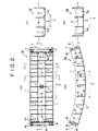
- Figs. 1 to 6 show an embodiment of a composite segment according to the present invention.
- main beam plates 1 are disposed at the opposite sides in an axial direction Y of a tunnel
- joint plates 2 are disposed at the opposite ends in a circumference direction Z of the tunnel
- back plates 3 are disposed at a bedrock side of the tunnel, respectively.
- a plurality of longitudinal ribs 4 are disposed at predetermined intervals between the main beam plates 1, 1 at the opposite sides, and a plurality of lateral ribs 5 are disposed at predetermined intervals between the joint plates 2, 2 at the opposite ends.
- Joints 6 which may join the mutually adjacent segments in the axial direction Y of the tunnel with each other simultaneously with the assemblage of the segments by using the principle of "hole-in-anchor", for instance, to insert one joint into the other joint in the axial direction Y of the tunnel so as to provide the tensile and shearing strengths equivalent to or more than those provided by a joining with bolts, are provided, as a joining between the mutually adjacent segments in the axial direction Y of the tunnel, at outer side parts of the main beam plates 1.
- joints which may join the mutually adjacent segments in the circumference direction Z of the tunnel with each other simultaneously with the assemblage of the segments by using wedge-system joints formed of dovetail grooves 7 and cotters 8 engaged with the dovetail grooves 7 to insert the joints in the axial direction Y of the tunnel, are provided, as a joining between the mutually adjacent segments in the circumference direction Z of the tunnel, at outer side parts of the joint plates 2.
- seal members 9 are mounted doubly, as a primary water-cutoff material between the mutually adjacent segments, to the outer side parts of the main beam plates 1 and the joint plates 2 so as to be placed at the opposite sides of the joints and also extend continuously in the axial direction Y of the main beam plates 1 and the joint plates 2 (i.e., continuously in the circumference direction Z of a steel shell 12 described later).
- corrosion-proof measures such as coating and baking are applied to all joining members such as the joints 6 and the cotters 8 to provide for a case where the seal members 9 fail to provide a water-cutoff performance.
- a plurality of projections 10 for fixing are projectedly provided, as connection parts for fixing main reinforcements 13 described later, on upper end parts of the joint plates 2 at predetermined intervals in the axial direction Y of the tunnel.
- the most general shape of the projections 10 is considered to be rectangular as shown in the drawing.
- the projections 10 are not limited to any particular shape, and the shape of projections 10 may be a circular one.
- the projections 10 also may be provided in a plurality of rows and besides in a staggered arrangement without being limited to a single row arrangement.
- a plurality of ribs 11 are projectedly provided, as fixing parts for shearing reinforcements 14 described later, on opposite side parts of the back plates 3 in the axial direction Y of the tunnel at predetermined intervals in the circumference direction Z of the tunnel, and holes 11a for fixing are provided in the ribs 11. It is to be noted that holes 5a similar to the holes 11a for fixing are also provided in the opposite ends of the lateral ribs 5.
- the dovetail groove 7 and the cotter 8 are both shaped to have a gradually smaller diameter in the insertion direction so as to be engaged with each other in accordance with a so-called wedge system, and are also provided in two stages in a radial direction of the tunnel so as to be placed at an outer side (the bedrock side) and an inner side (the tunnel side) with a so-called neutral axis X as a boundary therebetween. Further, the joints formed of the dovetail grooves 7 and the cotters 8 are provided in and on the joint plates 2 at the opposite ends in the circumference direction Z of the tunnel so as to have a predetermined length in the axial direction Y of the tunneL
- the joints formed of the dovetail grooves 7 and the cotters 8 as described above are provided in two stages with the neutral axis X as the boundary therebetween, it is possible to cope with an outer tensile stress state in which the surrounding earth pressure causes a tensile stress to act on the outer side of the neutral axis X, an inner tensile stress state in which the internal hudraulic pressure causes a tensile stress to act on the inner side of the neutral axis X or a whole cross-sectional tensile stress state.
- the above joints may be considered to have an extremely reasonable joining structure particularly suitable as the joining between the segments of the tunnel for water channel.
- the steel shell 12 having an arc-shaped curve with a predetermined curvature along the bedrock of the tunnel is provided, wherein a plurality of main reinforcements 13 and shearing reinforcements 14 are respectively disposed as reinforcing bars in the steel shell 12, and concrete 15 is filled therein.
- the steel shell 12 is, in principle, made of cast iron or cast steel also inclusive of spheroidal graphite cast iron, and the main beam plates 1, the joint plates 2 and the back plate 3 are provided in the integral structure by casting.
- the steel shell made of steel use of another assemble method of separately forming each of the main beam plates 1, the joint plates 2 and the back plates 3 to join them together later is also conceivable.
- corrosion-proof measures such as corrosion margin and corrosion-proof coating are applied to the surface of the steel shell 12.
- the plurality of main reinforcements 13 are disposed, in an arc-shaped arrangement along the circumference direction Z of the tunnel, between the joint plates 2 at the opposite ends, and end parts 13a of the main reinforcements 13 are fixed to the joint plates 2 at the opposite ends through fixing plates 16 respectively.
- the main reinforcements 13 also may be provided in succession at need by using lap joints to connect several pieces of reinforcements in the circumference direction Z of the tunnel.
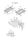
- the fixing plates 16 are provided in a thin tie plate-like configuration continuing in the axial direction Y of the tunnel, and holes 16a capable of being engaged with the projections 10 are provided in fixing plate portions close to one side of the fixing plates at predetermined intervals in the axial direction Y of the tunnel so as to correspond to the intervals of the projections 10.
- the end parts 13a of the main reinforcements 13 are respectively connected to fixing plate portions close to the other side of the fixing plates by welding.
- the plurality of main reinforcements 13 and the fixing plates 16 are previously assembled in a panel-like configuration of a size equivalent to a planar shape of the steel shell 12. If a larger size is particularly required, the main reinforcements 13 and the fixing plates 16 are assembled, as shown in Fig. 4(b), into two or three parts at need in the axial direction Y of the tunnel.
- the plurality of main reinforcements 13 and the fixing plates 16 thus assembled in the panel-like configuration are disposed in the steel shell 12, and the holes 16a of the fixing plates 16 and the projections 10 are engaged to fix the main reinforcements and the fixing plates in place in the steel shell 12.
- the previous assemblage of the plurality of main reinforcements 13 and the fixing plates 16 allows the plurality of main reinforcements to be disposed extremely efficiently.
- the shearing reinforcement 14 is provided in a portal configuration having a channel-like shape at the back plate 3-side (the bedrock side) by bending or the like, and hooks 14b, 14b projecting in the circumference direction Z of the tunnel are respectively provided on lower end parts of vertical parts 14a, 14a.
- the vertical parts 14a, 14a at the opposite sides are slightly bent toward an inner side at need as shown in Fig. 5(b), for instance. This allows the main reinforcements 13 and the concrete 15 to have a higher binding force.
- the plurality of shearing reinforcements 14 thus provided are disposed at predetermined intervals in the circumference direction Z of the tunnel so as to hold the plurality of main reinforcements 13 between the main beam plates 1,1 at the opposite sides, and the hooks 14b at the opposite ends are inserted into the fixing holes 11a of the ribs 11 or the fixing holes 5a of the lateral ribs 5 to fix the shearing reinforcements in place.
- the main reinforcements 13 and the shearing reinforcements 14 may be provided, so that both of the main reinforcements 13 and the shearing reinforcements 14 may be evaluated not only as a mere crack-proofing material for the concrete 15 but as structural members for the composite segment equally to the steel shell 12.
- back plates having a wave pattern makes the steel shell 12 adaptable to a configuration inclusive of one wherein a plurality of main beams are provided not only at the opposite side parts of the segment but also at the center part thereof, and besides, a plurality of longitudinal ribs are placed as a shearing reinforcement material in the steel shell 12.
- another method of fixing the end parts 13a of the main reinforcements 13 to the joint plates 2 of the steel shell 12 may be one of projectedly providing, at the inside of the joint plates, cylindrical fixing parts (not shown) as the connection parts for fixing the main reinforcements, while providing, at the end parts 13a of the main reinforcements 13, L-shaped hooks (not shown) capable of being inserted into the fixing parts to insert the hooks into the fixing parts.
- the fixing parts of the main reinforcements are provided at predetermined intervals in the axial direction Y of the tunnel so as to correspond to the intervals of arrangement of the main reinforcements 13.
- connection parts for fixing the main reinforcements are provided on the joint plates of the steel shell to fix the end parts of main reinforcements to the connection parts
- the ribs having the holes for fixing are projectedly provided on the inner side part of the steel shell
- the hooks for fixing are projectedly provided on the end parts of the shearing reinforcements, while the holes and the hooks are engaged to fix the end parts of the shearing reinforcements to the inner side part of the steel shell.
- the joints formed of the dovetail grooves and the cotters are provided in two stages as the joining between the mutually adjacent segments in the circumference direction Z of the tunnel, so that it is possible to cope with both of the stress states, i.e., the so-called outer tensile stress state and the so-called inner tensile stress state, and as a result, the composite segment is supposed to be particularly suitable as the lining material of the tunnel for water channel.
Landscapes
- Engineering & Computer Science (AREA)
- Architecture (AREA)
- Structural Engineering (AREA)
- Mining & Mineral Resources (AREA)
- Civil Engineering (AREA)
- Life Sciences & Earth Sciences (AREA)
- General Life Sciences & Earth Sciences (AREA)
- Geochemistry & Mineralogy (AREA)
- Geology (AREA)
- Lining And Supports For Tunnels (AREA)
Abstract
Description
Claims (3)
- In a composite segment wherein a plurality of main reinforcements and shearing reinforcements are respectively disposed in a steel shell formed of main beam plates, joint plates and back plates, while concrete is filled therein, and joints are provided in and on said joint plates, the composite segment, characterized in that connection parts for fixing the main reinforcements are provided on said joint plates to fix the end parts of said main reinforcements to said connection parts, and said joints are provided in two stages.
- In a composite segment wherein a plurality of main reinforcements and shearing reinforcements are respectively disposed in a steel shell formed of main beam plates, joint plates and back plates, while concrete is filled therein, and joints are provided in and on said joint plates, the composite segment, characterized in that ribs having holes for fixing are projectedly provided at an inner side part of said steel shell, and hooks for fixing are projectedly provided at end parts of said shearing reinforcements, while said holes and said hooks are engaged to fix the end parts of said shearing reinforcements to the inner side of said steel shell, and said joints are provided in two stages.
- The composite segment according to claim 1 or 2, wherein joints formed of dovetail grooves and cotters engaged therewith are provided as a joining.
Applications Claiming Priority (3)
| Application Number | Priority Date | Filing Date | Title |
|---|---|---|---|
| JP2000313806A JP3847072B2 (en) | 2000-10-13 | 2000-10-13 | Synthetic segment |
| JP2000313806 | 2000-10-13 | ||
| PCT/JP2001/009010 WO2002031317A1 (en) | 2000-10-13 | 2001-10-12 | Composite segment |
Publications (3)
| Publication Number | Publication Date |
|---|---|
| EP1326004A1 true EP1326004A1 (en) | 2003-07-09 |
| EP1326004A4 EP1326004A4 (en) | 2005-01-12 |
| EP1326004B1 EP1326004B1 (en) | 2006-05-17 |
Family
ID=18793162
Family Applications (1)
| Application Number | Title | Priority Date | Filing Date |
|---|---|---|---|
| EP01974837A Expired - Lifetime EP1326004B1 (en) | 2000-10-13 | 2001-10-12 | Composite segment |
Country Status (6)
| Country | Link |
|---|---|
| EP (1) | EP1326004B1 (en) |
| JP (1) | JP3847072B2 (en) |
| KR (1) | KR100565813B1 (en) |
| CN (1) | CN1330850C (en) |
| DE (1) | DE60119758T2 (en) |
| WO (1) | WO2002031317A1 (en) |
Cited By (3)
| Publication number | Priority date | Publication date | Assignee | Title |
|---|---|---|---|---|
| EP1701002A1 (en) * | 2005-03-10 | 2006-09-13 | Günter Eberhardt | Device with a cage for a reinforced concrete tubbing |
| JP2017043884A (en) * | 2015-08-24 | 2017-03-02 | 株式会社大林組 | Joint structure of segment |
| JP2019056287A (en) * | 2017-09-22 | 2019-04-11 | 鹿島建設株式会社 | Tunnel and tunnel construction method |
Families Citing this family (22)
| Publication number | Priority date | Publication date | Assignee | Title |
|---|---|---|---|---|
| JP2007056453A (en) * | 2005-08-22 | 2007-03-08 | Yokogawa Bridge Corp | Shear reinforcement bar structure of floor slab |
| KR100717390B1 (en) * | 2005-09-14 | 2007-05-11 | 박창순 | Prefabricated Panels for Excavation Tunnels |
| JP2009084976A (en) * | 2007-10-03 | 2009-04-23 | Tokyu Construction Co Ltd | Structure of segment |
| JP4920626B2 (en) * | 2008-04-08 | 2012-04-18 | 新日本製鐵株式会社 | Synthetic segment |
| JP4949352B2 (en) * | 2008-11-04 | 2012-06-06 | 新日本製鐵株式会社 | Primary lining body of concrete-filled steel segment and tunnel |
| JP5960942B2 (en) * | 2009-10-27 | 2016-08-02 | 株式会社Ihi建材工業 | segment |
| JP6159057B2 (en) * | 2011-04-12 | 2017-07-05 | 鹿島建設株式会社 | Synthetic concrete filled steel segment |
| JP2012122330A (en) * | 2012-03-28 | 2012-06-28 | Tokyu Construction Co Ltd | Structure of composite segment |
| CN103557014B (en) * | 2013-10-21 | 2018-03-02 | 上海建工地下工程技术有限公司 | A kind of tunnel segment structure and its assembling method suitable for Rectangular Tunnel |
| CN103821537B (en) * | 2014-03-12 | 2016-01-13 | 上海市机械施工集团有限公司 | The splicing processing method of rectangular shield section of jurisdiction and shear structure thereof |
| CN103912286B (en) * | 2014-03-14 | 2016-07-06 | 上海市政工程设计研究总院(集团)有限公司 | Prevent the method that multiple tube strip terminal plate deforms |
| JP5906277B2 (en) * | 2014-05-02 | 2016-04-20 | 株式会社Ihi建材工業 | segment |
| JP6033937B2 (en) * | 2015-09-24 | 2016-11-30 | 株式会社Ihi建材工業 | segment |
| CN105927245B (en) * | 2016-04-27 | 2018-10-23 | 中铁十二局集团安徽混凝土制品有限公司 | A kind of novel segment steel structure framework manufacturing method |
| JP6773279B2 (en) * | 2016-08-10 | 2020-10-21 | 清水建設株式会社 | Fire resistance test method for segments |
| CN109595005B (en) * | 2018-11-20 | 2024-04-02 | 山东万广建设工程有限公司 | Shell advance type non-excavation tunnel construction structure and construction method |
| CN110056371A (en) * | 2019-05-28 | 2019-07-26 | 长安大学 | A kind of tunnel morning strong supporting system and its installation method |
| CN110043293A (en) * | 2019-05-28 | 2019-07-23 | 长安大学 | A kind of the tunnel morning strong supporting system and its installation method of bayonet joint |
| JP7568930B2 (en) * | 2021-03-09 | 2024-10-17 | 日本製鉄株式会社 | Segments and segment connection structure |
| JP7854798B2 (en) * | 2021-12-22 | 2026-05-07 | Jfe建材株式会社 | Composite segments and earth retaining structures |
| CN114718599B (en) * | 2022-03-29 | 2023-08-29 | 同济大学 | Concrete embedded inflation/liquid steel pipe intelligent duct piece |
| JP2024013426A (en) * | 2022-07-20 | 2024-02-01 | Jfe建材株式会社 | Method of manufacturing synthetic segments |
Family Cites Families (10)
| Publication number | Priority date | Publication date | Assignee | Title |
|---|---|---|---|---|
| GB1502207A (en) * | 1975-07-18 | 1978-02-22 | Tsuzuki J | Concrete segment |
| FR2582718B1 (en) * | 1985-05-28 | 1987-08-28 | Francois Entreprises Cie | FORMWORK AND SHIELDING WALL |
| JPH09203297A (en) * | 1996-01-25 | 1997-08-05 | Nippon Kokan Light Steel Kk | Joint structure of rc segment |
| JP3100127B2 (en) * | 1997-11-05 | 2000-10-16 | 西松建設株式会社 | Lining segment |
| JP3272670B2 (en) * | 1997-12-08 | 2002-04-08 | 株式会社大林組 | Segment joint structure |
| JP3504490B2 (en) * | 1998-02-20 | 2004-03-08 | 株式会社大林組 | Segment and segment joining method |
| JP3962478B2 (en) * | 1998-03-12 | 2007-08-22 | 大日本土木株式会社 | Segment joints and segments for tunnel lining work |
| JP3929590B2 (en) * | 1998-04-03 | 2007-06-13 | 石川島建材工業株式会社 | Segment joint structure |
| JP4040174B2 (en) * | 1998-06-12 | 2008-01-30 | 石川島建材工業株式会社 | segment |
| JP3480338B2 (en) * | 1998-11-02 | 2003-12-15 | 鹿島建設株式会社 | Segment and tunnel lining method |
-
2000
- 2000-10-13 JP JP2000313806A patent/JP3847072B2/en not_active Expired - Fee Related
-
2001
- 2001-10-12 DE DE60119758T patent/DE60119758T2/en not_active Expired - Fee Related
- 2001-10-12 CN CNB018172792A patent/CN1330850C/en not_active Expired - Fee Related
- 2001-10-12 KR KR1020037005006A patent/KR100565813B1/en not_active Expired - Fee Related
- 2001-10-12 WO PCT/JP2001/009010 patent/WO2002031317A1/en not_active Ceased
- 2001-10-12 EP EP01974837A patent/EP1326004B1/en not_active Expired - Lifetime
Cited By (3)
| Publication number | Priority date | Publication date | Assignee | Title |
|---|---|---|---|---|
| EP1701002A1 (en) * | 2005-03-10 | 2006-09-13 | Günter Eberhardt | Device with a cage for a reinforced concrete tubbing |
| JP2017043884A (en) * | 2015-08-24 | 2017-03-02 | 株式会社大林組 | Joint structure of segment |
| JP2019056287A (en) * | 2017-09-22 | 2019-04-11 | 鹿島建設株式会社 | Tunnel and tunnel construction method |
Also Published As
| Publication number | Publication date |
|---|---|
| CN1469966A (en) | 2004-01-21 |
| KR100565813B1 (en) | 2006-03-30 |
| EP1326004A4 (en) | 2005-01-12 |
| JP2002121999A (en) | 2002-04-26 |
| DE60119758D1 (en) | 2006-06-22 |
| DE60119758T2 (en) | 2007-05-03 |
| EP1326004B1 (en) | 2006-05-17 |
| KR20030081317A (en) | 2003-10-17 |
| CN1330850C (en) | 2007-08-08 |
| JP3847072B2 (en) | 2006-11-15 |
| WO2002031317A1 (en) | 2002-04-18 |
Similar Documents
| Publication | Publication Date | Title |
|---|---|---|
| EP1326004B1 (en) | Composite segment | |
| US4545701A (en) | Tunnel wall structure | |
| EP3751094B1 (en) | Couplings for coupling pre-cast construction segments together and pre-cast construction segments having such couplings | |
| JP2009154400A (en) | Synthetic segment | |
| JP2011127350A (en) | Segment | |
| JP2023036068A (en) | Segment piece and segment ring | |
| US4095433A (en) | Tunnel support structure using built-up pipe support set, and unit pipe support member therefor | |
| JP2011157755A (en) | Steel segment and composite segment | |
| JP5160521B2 (en) | Synthetic segment | |
| JP2001311396A (en) | Synthetic segment | |
| JP2021063394A (en) | Composite segment | |
| JP6314415B2 (en) | Synthetic segment and method for producing synthetic segment | |
| JP7682072B2 (en) | segment | |
| JP4874076B2 (en) | Synthetic segment | |
| JP2021063393A (en) | Composite segment | |
| JP5245547B2 (en) | Segment and manufacturing method thereof | |
| JP3257502B2 (en) | Construction method of steel segment and tunnel lining | |
| JPH11270293A (en) | Steel segment and tunnel lining body composed of steel segment | |
| JP3773332B2 (en) | Segment piece for sinking body | |
| JP7720763B2 (en) | segment | |
| JPH05295991A (en) | Segment for tunnel lining | |
| JP2023057363A (en) | segment | |
| JPH11101095A (en) | Lining segment, assembly structure of lining segment, and method of assembling lining segment | |
| JPH0932491A (en) | Composite segment | |
| KR200414531Y1 (en) | RF segment connector for shield tunnel method |
Legal Events
| Date | Code | Title | Description |
|---|---|---|---|
| PUAI | Public reference made under article 153(3) epc to a published international application that has entered the european phase |
Free format text: ORIGINAL CODE: 0009012 |
|
| 17P | Request for examination filed |
Effective date: 20030414 |
|
| AK | Designated contracting states |
Designated state(s): BE CH DE DK FR GB GR IE IT LI NL SE |
|
| RAP1 | Party data changed (applicant data changed or rights of an application transferred) |
Owner name: KUBOTA CORPORATION Owner name: KAJIMA CORPORATION |
|
| A4 | Supplementary search report drawn up and despatched |
Effective date: 20041201 |
|
| RIC1 | Information provided on ipc code assigned before grant |
Ipc: 7E 21D 11/04 A Ipc: 7E 21D 9/08 B |
|
| 17Q | First examination report despatched |
Effective date: 20050630 |
|
| GRAP | Despatch of communication of intention to grant a patent |
Free format text: ORIGINAL CODE: EPIDOSNIGR1 |
|
| GRAS | Grant fee paid |
Free format text: ORIGINAL CODE: EPIDOSNIGR3 |
|
| GRAA | (expected) grant |
Free format text: ORIGINAL CODE: 0009210 |
|
| AK | Designated contracting states |
Kind code of ref document: B1 Designated state(s): BE CH DE DK FR GB GR IE IT LI NL SE |
|
| PG25 | Lapsed in a contracting state [announced via postgrant information from national office to epo] |
Ref country code: IT Free format text: LAPSE BECAUSE OF FAILURE TO SUBMIT A TRANSLATION OF THE DESCRIPTION OR TO PAY THE FEE WITHIN THE PRESCRIBED TIME-LIMIT;WARNING: LAPSES OF ITALIAN PATENTS WITH EFFECTIVE DATE BEFORE 2007 MAY HAVE OCCURRED AT ANY TIME BEFORE 2007. THE CORRECT EFFECTIVE DATE MAY BE DIFFERENT FROM THE ONE RECORDED. Effective date: 20060517 Ref country code: CH Free format text: LAPSE BECAUSE OF FAILURE TO SUBMIT A TRANSLATION OF THE DESCRIPTION OR TO PAY THE FEE WITHIN THE PRESCRIBED TIME-LIMIT Effective date: 20060517 Ref country code: LI Free format text: LAPSE BECAUSE OF FAILURE TO SUBMIT A TRANSLATION OF THE DESCRIPTION OR TO PAY THE FEE WITHIN THE PRESCRIBED TIME-LIMIT Effective date: 20060517 Ref country code: BE Free format text: LAPSE BECAUSE OF FAILURE TO SUBMIT A TRANSLATION OF THE DESCRIPTION OR TO PAY THE FEE WITHIN THE PRESCRIBED TIME-LIMIT Effective date: 20060517 |
|
| REG | Reference to a national code |
Ref country code: GB Ref legal event code: FG4D |
|
| REG | Reference to a national code |
Ref country code: CH Ref legal event code: EP |
|
| REG | Reference to a national code |
Ref country code: IE Ref legal event code: FG4D |
|
| REF | Corresponds to: |
Ref document number: 60119758 Country of ref document: DE Date of ref document: 20060622 Kind code of ref document: P |
|
| PG25 | Lapsed in a contracting state [announced via postgrant information from national office to epo] |
Ref country code: SE Free format text: LAPSE BECAUSE OF FAILURE TO SUBMIT A TRANSLATION OF THE DESCRIPTION OR TO PAY THE FEE WITHIN THE PRESCRIBED TIME-LIMIT Effective date: 20060817 Ref country code: DK Free format text: LAPSE BECAUSE OF FAILURE TO SUBMIT A TRANSLATION OF THE DESCRIPTION OR TO PAY THE FEE WITHIN THE PRESCRIBED TIME-LIMIT Effective date: 20060817 |
|
| PG25 | Lapsed in a contracting state [announced via postgrant information from national office to epo] |
Ref country code: IE Free format text: LAPSE BECAUSE OF NON-PAYMENT OF DUE FEES Effective date: 20061012 |
|
| REG | Reference to a national code |
Ref country code: CH Ref legal event code: PL |
|
| ET | Fr: translation filed | ||
| PLBE | No opposition filed within time limit |
Free format text: ORIGINAL CODE: 0009261 |
|
| STAA | Information on the status of an ep patent application or granted ep patent |
Free format text: STATUS: NO OPPOSITION FILED WITHIN TIME LIMIT |
|
| 26N | No opposition filed |
Effective date: 20070220 |
|
| PG25 | Lapsed in a contracting state [announced via postgrant information from national office to epo] |
Ref country code: GR Free format text: LAPSE BECAUSE OF FAILURE TO SUBMIT A TRANSLATION OF THE DESCRIPTION OR TO PAY THE FEE WITHIN THE PRESCRIBED TIME-LIMIT Effective date: 20060818 |
|
| PGFP | Annual fee paid to national office [announced via postgrant information from national office to epo] |
Ref country code: NL Payment date: 20081005 Year of fee payment: 8 |
|
| PGFP | Annual fee paid to national office [announced via postgrant information from national office to epo] |
Ref country code: DE Payment date: 20081014 Year of fee payment: 8 |
|
| PGFP | Annual fee paid to national office [announced via postgrant information from national office to epo] |
Ref country code: FR Payment date: 20081014 Year of fee payment: 8 |
|
| PGFP | Annual fee paid to national office [announced via postgrant information from national office to epo] |
Ref country code: GB Payment date: 20081008 Year of fee payment: 8 |
|
| REG | Reference to a national code |
Ref country code: NL Ref legal event code: V1 Effective date: 20100501 |
|
| REG | Reference to a national code |
Ref country code: FR Ref legal event code: ST Effective date: 20100630 |
|
| PG25 | Lapsed in a contracting state [announced via postgrant information from national office to epo] |
Ref country code: FR Free format text: LAPSE BECAUSE OF NON-PAYMENT OF DUE FEES Effective date: 20091102 Ref country code: DE Free format text: LAPSE BECAUSE OF NON-PAYMENT OF DUE FEES Effective date: 20100501 Ref country code: NL Free format text: LAPSE BECAUSE OF NON-PAYMENT OF DUE FEES Effective date: 20100501 |
|
| PG25 | Lapsed in a contracting state [announced via postgrant information from national office to epo] |
Ref country code: GB Free format text: LAPSE BECAUSE OF NON-PAYMENT OF DUE FEES Effective date: 20091012 |