EP1325284B1 - Monitoring optically powered actuators - Google Patents
Monitoring optically powered actuators Download PDFInfo
- Publication number
- EP1325284B1 EP1325284B1 EP01963138A EP01963138A EP1325284B1 EP 1325284 B1 EP1325284 B1 EP 1325284B1 EP 01963138 A EP01963138 A EP 01963138A EP 01963138 A EP01963138 A EP 01963138A EP 1325284 B1 EP1325284 B1 EP 1325284B1
- Authority
- EP
- European Patent Office
- Prior art keywords
- optical
- monitoring system
- optical path
- source
- sensing
- Prior art date
- Legal status (The legal status is an assumption and is not a legal conclusion. Google has not performed a legal analysis and makes no representation as to the accuracy of the status listed.)
- Expired - Lifetime
Links
- 238000012544 monitoring process Methods 0.000 title claims abstract description 31
- 230000003287 optical effect Effects 0.000 claims abstract description 80
- 239000000835 fiber Substances 0.000 claims abstract description 25
- 238000000034 method Methods 0.000 claims description 11
- 238000001228 spectrum Methods 0.000 claims description 10
- 238000001514 detection method Methods 0.000 claims 1
- 239000013307 optical fiber Substances 0.000 abstract description 27
- 238000012545 processing Methods 0.000 abstract description 7
- 230000005540 biological transmission Effects 0.000 description 6
- 239000012530 fluid Substances 0.000 description 5
- VYPSYNLAJGMNEJ-UHFFFAOYSA-N Silicium dioxide Chemical compound O=[Si]=O VYPSYNLAJGMNEJ-UHFFFAOYSA-N 0.000 description 4
- 230000008901 benefit Effects 0.000 description 3
- 238000005259 measurement Methods 0.000 description 3
- 238000012986 modification Methods 0.000 description 3
- 230000004048 modification Effects 0.000 description 3
- 238000010586 diagram Methods 0.000 description 2
- 239000011521 glass Substances 0.000 description 2
- 230000008569 process Effects 0.000 description 2
- 230000035945 sensitivity Effects 0.000 description 2
- 229910001285 shape-memory alloy Inorganic materials 0.000 description 2
- 239000000377 silicon dioxide Substances 0.000 description 2
- 230000001133 acceleration Effects 0.000 description 1
- 238000004458 analytical method Methods 0.000 description 1
- 238000010420 art technique Methods 0.000 description 1
- 238000013528 artificial neural network Methods 0.000 description 1
- 230000000712 assembly Effects 0.000 description 1
- 238000000429 assembly Methods 0.000 description 1
- 230000002457 bidirectional effect Effects 0.000 description 1
- 230000000903 blocking effect Effects 0.000 description 1
- 238000009529 body temperature measurement Methods 0.000 description 1
- 230000008859 change Effects 0.000 description 1
- 238000004891 communication Methods 0.000 description 1
- 238000013461 design Methods 0.000 description 1
- 229920001971 elastomer Polymers 0.000 description 1
- 239000000806 elastomer Substances 0.000 description 1
- 230000005674 electromagnetic induction Effects 0.000 description 1
- 239000000446 fuel Substances 0.000 description 1
- 230000006870 function Effects 0.000 description 1
- 231100001261 hazardous Toxicity 0.000 description 1
- 230000036039 immunity Effects 0.000 description 1
- 238000012423 maintenance Methods 0.000 description 1
- 238000004519 manufacturing process Methods 0.000 description 1
- 239000000463 material Substances 0.000 description 1
- 239000004065 semiconductor Substances 0.000 description 1
- 230000003068 static effect Effects 0.000 description 1
- 230000002277 temperature effect Effects 0.000 description 1
- 230000000930 thermomechanical effect Effects 0.000 description 1
Images


Classifications
-
- F—MECHANICAL ENGINEERING; LIGHTING; HEATING; WEAPONS; BLASTING
- F15—FLUID-PRESSURE ACTUATORS; HYDRAULICS OR PNEUMATICS IN GENERAL
- F15B—SYSTEMS ACTING BY MEANS OF FLUIDS IN GENERAL; FLUID-PRESSURE ACTUATORS, e.g. SERVOMOTORS; DETAILS OF FLUID-PRESSURE SYSTEMS, NOT OTHERWISE PROVIDED FOR
- F15B13/00—Details of servomotor systems ; Valves for servomotor systems
- F15B13/02—Fluid distribution or supply devices characterised by their adaptation to the control of servomotors
- F15B13/04—Fluid distribution or supply devices characterised by their adaptation to the control of servomotors for use with a single servomotor
- F15B13/042—Fluid distribution or supply devices characterised by their adaptation to the control of servomotors for use with a single servomotor operated by fluid pressure
- F15B13/043—Fluid distribution or supply devices characterised by their adaptation to the control of servomotors for use with a single servomotor operated by fluid pressure with electrically-controlled pilot valves
- F15B13/0438—Fluid distribution or supply devices characterised by their adaptation to the control of servomotors for use with a single servomotor operated by fluid pressure with electrically-controlled pilot valves the pilot valves being of the nozzle-flapper type
-
- F—MECHANICAL ENGINEERING; LIGHTING; HEATING; WEAPONS; BLASTING
- F16—ENGINEERING ELEMENTS AND UNITS; GENERAL MEASURES FOR PRODUCING AND MAINTAINING EFFECTIVE FUNCTIONING OF MACHINES OR INSTALLATIONS; THERMAL INSULATION IN GENERAL
- F16K—VALVES; TAPS; COCKS; ACTUATING-FLOATS; DEVICES FOR VENTING OR AERATING
- F16K31/00—Actuating devices; Operating means; Releasing devices
-
- G—PHYSICS
- G01—MEASURING; TESTING
- G01D—MEASURING NOT SPECIALLY ADAPTED FOR A SPECIFIC VARIABLE; ARRANGEMENTS FOR MEASURING TWO OR MORE VARIABLES NOT COVERED IN A SINGLE OTHER SUBCLASS; TARIFF METERING APPARATUS; MEASURING OR TESTING NOT OTHERWISE PROVIDED FOR
- G01D5/00—Mechanical means for transferring the output of a sensing member; Means for converting the output of a sensing member to another variable where the form or nature of the sensing member does not constrain the means for converting; Transducers not specially adapted for a specific variable
- G01D5/26—Mechanical means for transferring the output of a sensing member; Means for converting the output of a sensing member to another variable where the form or nature of the sensing member does not constrain the means for converting; Transducers not specially adapted for a specific variable characterised by optical transfer means, i.e. using infrared, visible, or ultraviolet light
- G01D5/32—Mechanical means for transferring the output of a sensing member; Means for converting the output of a sensing member to another variable where the form or nature of the sensing member does not constrain the means for converting; Transducers not specially adapted for a specific variable characterised by optical transfer means, i.e. using infrared, visible, or ultraviolet light with attenuation or whole or partial obturation of beams of light
- G01D5/34—Mechanical means for transferring the output of a sensing member; Means for converting the output of a sensing member to another variable where the form or nature of the sensing member does not constrain the means for converting; Transducers not specially adapted for a specific variable characterised by optical transfer means, i.e. using infrared, visible, or ultraviolet light with attenuation or whole or partial obturation of beams of light the beams of light being detected by photocells
- G01D5/353—Mechanical means for transferring the output of a sensing member; Means for converting the output of a sensing member to another variable where the form or nature of the sensing member does not constrain the means for converting; Transducers not specially adapted for a specific variable characterised by optical transfer means, i.e. using infrared, visible, or ultraviolet light with attenuation or whole or partial obturation of beams of light the beams of light being detected by photocells influencing the transmission properties of an optical fibre
- G01D5/35306—Mechanical means for transferring the output of a sensing member; Means for converting the output of a sensing member to another variable where the form or nature of the sensing member does not constrain the means for converting; Transducers not specially adapted for a specific variable characterised by optical transfer means, i.e. using infrared, visible, or ultraviolet light with attenuation or whole or partial obturation of beams of light the beams of light being detected by photocells influencing the transmission properties of an optical fibre using an interferometer arrangement
- G01D5/35309—Mechanical means for transferring the output of a sensing member; Means for converting the output of a sensing member to another variable where the form or nature of the sensing member does not constrain the means for converting; Transducers not specially adapted for a specific variable characterised by optical transfer means, i.e. using infrared, visible, or ultraviolet light with attenuation or whole or partial obturation of beams of light the beams of light being detected by photocells influencing the transmission properties of an optical fibre using an interferometer arrangement using multiple waves interferometer
- G01D5/35316—Mechanical means for transferring the output of a sensing member; Means for converting the output of a sensing member to another variable where the form or nature of the sensing member does not constrain the means for converting; Transducers not specially adapted for a specific variable characterised by optical transfer means, i.e. using infrared, visible, or ultraviolet light with attenuation or whole or partial obturation of beams of light the beams of light being detected by photocells influencing the transmission properties of an optical fibre using an interferometer arrangement using multiple waves interferometer using a Bragg gratings
Definitions
- the present invention relates to systems incorporating an optically powered actuator for example within control-by-light and power-by-light valves.
- US Patent 5,709,245 discloses an optically controlled actuator employing a laser, an optical fibre and a photocell which energises coils of an electro-hydraulic valve. This document corresponds generally to the preambles of claims 1 and 14.
- EP-A-0954743 discloses an arrangement in which optical sensors are employed with an electrical pump operated via an electrical cable from a power supply. Bragg gratings are used to detect temperature, acceleration and pressure respectively. Static and dynamic wavelength monitoring systems are employed, coupled to an optical fibre via couplers.
- the present invention seeks to provide an optically controlled/powered actuator having a built-in sensing arrangement.
- the present invention further seeks to provide an arrangement for monitoring the output of the integrated sensor.
- a monitoring system for an optically powered and/or controlled actuator arrangement comprising an optical path arranged to be connected between at least one optical source and the actuator arrangement for supplying power and/or control information thereto, the actuator arrangement including means for converting the optical power and/or control information characterised in that the actuator arrangement further comprises means for sensing the operation thereof and providing an optical data output back through said optical path, and in that means are connected to the optical path to monitor the output of the sensing means.
- the sensing means is also operated by said optical source.
- the sensing means comprises one or more fibre Bragg gratings.
- the differential pressure of the actuator system may be sensed by an arrangement incorporating a fibre Bragg grating located adjacent to at least one diaphragm.
- the fibre Bragg grating is mounted between two diaphragms arranged to be exposed to different pressures.
- a fibre Bragg grating may be provided for sensing the temperature; this grating may be used to compensate for unwanted temperature effects on the differential pressure grating.
- the monitoring system may comprise at least two optical sources, a first of which is used for supplying power and/or control information, and a second of which is used to detect interruption of the optical path and is arranged to turn off the first source in the event of such interruption.
- the output of the sources is controlled by a signal from the monitoring means.
- a signal from the monitoring means is controlled by a signal from the monitoring means.
- the actuator arrangement is at a location remote from the optical source.
- Such an arrangement has the advantage that the components at the end of the optical fibre remote from the source can be relatively simple and robust and have no local power requirements.
- a method of using one or more light sources at a first end of an optical path for powering and/or controlling a valve or actuator at a second end of the optical path characterised in that light from the source(s) is used to interact with one or more sensors, at or adjacent the second end of the optical path, to produce sensing signals, and in that the method further comprises detecting the sensing signals at or adjacent the first end of the optical path.
- FIG. 1 shows a monitoring system 10 comprising an optical power source in the form of a laser 11 for generating light to operate a power-by-light (PBL) hydraulic valve arrangement 15.
- the valve is used to control flow-rate, flow direction and/or pressure in a hydraulic system.
- a high temperature grade, low numerical aperture (NA) multimode optical fibre 13 connects source 11 to integrated optical fibre based sensors 14 and, via a further optical fibre 23, to the valve 15 which incorporates a piezoelectric actuator. Hydraulic inlet and outlet ports are indicated schematically at 18 and 19 respectively.
- NA numerical aperture
- the sensors 14 include a flow sensor and a temperature sensor and will be described in further detail below.
- FIG 2 shows the hydraulic connections between the sensor arrangement 14 and the valve 15. It will be noted that the ports P1 and P2 of the sensor arrangement are in communication with the hydraulic passage 27 between inlet 18 and outlet 19. An orifice plate 20 is located in passage 27 between ports P1 and P2.
- a 150mW laser source emitting an 810nm peak wavelength uses a 50:50 multiple mode optical fibre coupler 12.
- One output end of the coupler is connected to multimode optical fibre Bragg gratings (mm-FBGs) which are used for differential pressure sensing and temperature sensing.
- the other end (at the input side) of the optical fibre coupler is connected to an optical spectrum analyser.
- the optical source 11 is an SLD 5mW, L3302-01 leaser from Hamamatsu emitting an 845nm peak wavelength.
- the optical power is launched into a 50:50 single mode optical fibre coupler 12.
- Two output ends of the coupler are connected to optical fibre Bragg gratings (FBGs) which are used on a diaphragm means of the valve arrangement.
- FBGs optical fibre Bragg gratings
- the other end (at the input side) of the optical fibre coupler is connected to an optical spectrum analyser (e.g. an Anritsu model MS99A, resolution 0.1nm).
- the optical fibre 13 is used to channel the sensing information from sensors 14 in the opposite direction to the power supplied by source 11.
- the information is channelled by fibre optic coupler or beam splitter 12 from the main optical fibre via a separate optical path 22 into an optical signal processor and monitoring unit 16.
- the unit 16 detects and converts the optical signal sent reflected from the sensors in the system to electronic information.
- the electrical information is then adapted and supplied to a further unit 17 including a signal processor, a control panel, a user interface and a display unit.
- the adapted information is supplied to a control panel display.
- a control link from unit 17 to the laser 11 is indicated by numeral 32.
- the optical fibre sensors 14 are used for sensing the PBL valve operation and allow most of the optical power to pass through to the PBL valve or actuator 15.
- the sensors 14 comprise multimode fibre Bragg gratings (MM-FBGs) to sense the hydraulic flowrate, hydraulic pressure and fluid temperature in the hydraulic PBL valve system.
- MM-FBGs multimode fibre Bragg gratings
- one MM-FBG sensor 41 for strain is mounted between two diaphragms 42, Figure 3 , to sense the differential pressure proportional to flow-rate through the PBL valve 15.
- the second MM-FBG sensor 43 is incorporated as a temperature reference and compensates the differential pressure (DP) based flow sensor.
- the components are mounted in a housing 44.
- the sensor 43 is located so as not to be affected by movements of the diaphragms 42.
- the temperature sensing MM-FBG, pressure sensing MM-FBG and PBL valve are connected in series through the same optical power transmission line 13, 23.
- Information regarding the fluid flowrate is reflected and returned up the same fibre waveguide 13 in the form of differential optical wavelength shifts.
- the unit 16 employs a wavelength demodulator to process the signals.
- the temperature information is also extracted.
- Wavelength division modulation (WDM) permits the strain and temperature signals to be extracted separately.
- Figure 4 shows an optical power valve arrangement 15 for hydraulic or pneumatic application, which is used to open and close a power-by-light valve.
- the arrangement comprises a piezoelectric multilayer or bimorph bender element 151, an elastomer blocking plate 152, an inlet nozzle 18, an outlet nozzle 19 and a valve case or housing 154.
- the valve is driven by electrical power, which is converted from optical power by a photovoltaic converter 155 and DC-DC converter 156.
- the optical power output from the sensor 14 is fed into the photo voltaic converter 155 to convert into electrical power to drive element 151 via electrical leads 160 which are connected to the fixed clamp end 161 of element 151.
- a preferred hydraulic valve arrangement 15 has an operating pressure of greater than 950kpa.
- the orifice plate 20, Figure 2 is used to restrict the fluid flow and cause a pressure drop across itself.
- the thin plate diaphragms 42 are strained by applying this differential pressure to them.
- a single FBG 41 may be mounted on a single diaphragm 42, which is arranged such that the radial strain on the diaphragm surface is related to the applied pressure.
- the strain is transformed into optical information by using the optical fibre Bragg grating 41 mounted on the diaphragm(s) 42.
- the second grating 43 is for temperature measurement and temperature compensation.
- the differential wavelength shift between the reflected signals from the two gratings provides a measurement of the fluid flow-rate.
- Temperature variation causes the variation in the reflected wavelengths to be the same and therefore there is no change in differential wavelength (assuming perfect symmetry).
- Typical operating characteristics are a fluid flow-rate between 0-800cm 3 /s at a pressure of 50 Bar and temperature range of -4°C to 160°C, preferably 25°C to 75°C.
- Bragg gratings are fabricated on multimode or single mode silica optical fibre.
- the output ends of each FBG sensor are connected directly to the valve to supply it with power.
- the DP sensor is connected to the differential pressure across the orifice plate.
- the above system is especially suitable for long transmission lines, typically about 5km, thus permitting remote control of the valve 15.
- the use of wavelength modulation and demodulation is especially suitable for long distance applications.
- the system can resist harsh environments since the actuator in the valve is capable of operating in high temperatures.
- the actuator also has the advantage of relatively low power consumption.
- multimode fibre as the line 13 allows relatively high levels of power to be transmitted, over shorter distances, whereas single mode fibre is generally preferred for use over longer distances.
- the system is self-contained in that the source 11 generates light to operate valve 15 and all the sensors in the system.
- the optical power attenuation associated with the sensors is small in comparison with the power passing through to actuate the valve 15.
- the sensors 14 pass the optical power directly to the valve 15 without any coupler or splitter between them.
- the need is eliminated for complicated and unreliable optical assemblies at the remote end, ie adjacent to valve 15.
- the optical control loop utilises the same fibre for the majority of the transmission line where power and sensing signals travel in opposite directions.
- This control system can be operated without using optical fibre couplers or beam splitters at the remote end.
- Using a single fibre optic transmission line reduces costs, complexity, maintenance and allows easier fibre deployment.
- Variation in optical power levels to the valve 15 can be used to vary the flow rate through the valve. Variation of flow rate through the valve 15 can be detected using this system. Power levels to the valve are controlled using pulse width modulation to the valve or by the power setting for continuous wave emission from the light source.
- the optical source 11 may be an electrical light source or a semiconductor light source, white light, Light Emitting Diode (LED), Super Luminescent Diode (SLD), Edge-emitting LED (ELED), Laser Diode (LD) or Vertical Cavity Surface Emitting Laser Diode (VCSEL).
- the transmission line 13 may be multimode or single-mode optical fibres or other forms of optical waveguide. The same specification is used for the coupler/splitter 12 as for the optical fibre 13.
- the beam splitter or combiner 12 may be a cube glass beam splitter/combiner, angle glass, wavelength division multiplexing/demultiplexing (WDM/DWDM) coupler, silica-based buried channel waveguides coupler or optical couplers/splitters.
- WDM/DWDM wavelength division multiplexing/demultiplexing
- the actuator in the valve 15 may be piezoelectric, ferroelectric, electromagnetic, photostrictive, a shape memory alloy or electrostatic.
- the actuator utilises the extremely small amounts of power supplied to operate effectively.
- sensors 14 and actuator/valve 15 may be combined or separated as desired.
- sensors 14 may employ the techniques of microbending, Fabry-Perot sensing, or Rayleigh or Brillouin scattering.
- the optical monitoring and processing unit may include an optical spectrum analyser, a CCD array grating, tuneable filter, a scanning filter, an optical interferometer, an optical wavelength edge detector and an optical power ratio detector. However, only a single detector may be provided.
- the electronic processing can be microprocessor based or micro-controller based.
- Software can also be adapted for closed-loop feedback control of the light source 11.
- the optically powered actuator system of Figure 1 may be modified to employ more than one light source for distributed sensors.
- Figure 5 shows a monitoring system 110 with a laser source 11 and a wider bandwidth super luminescent diode 111 for the flow and temperature sensors.
- a 1 x Z bidirectional fibre optic coupler 12 is employed.
- the second optical source 111 can be used to monitor when the optical fibre is broken.
- the laser source 11 is interlocked with the second source monitoring arrangement so that the laser is turned off for safety reasons if a broken fibre is detected.
- the optical fibre 13 in the system can utilise either multimode or single mode optical fibre.
- a multimode fibre is the most suitable for the short distance system ( ⁇ 5km), because it is easy to couple to optical sources and inexpensive components.
- a single mode optical fibre is preferred when the system distance is over 5km, because the single mode fibre has a very low attenuation compared to the multimode fibre.
- an optical fibre based flow sensor or flow switch 14 of Figure 5 employs wavelength-based modulation and it allows the optical power to pass into the actuator unit of valve 15.
- a differential pressure flow sensor 14 can use an optical fibre Bragg grating in either single mode or multimode.
- the optical signals from both light sources 11, 111 are transmitted into the sensor 14.
- the laser power passing through the FBG sensors 14 into the actuator and the optical power from second light source 111 is reflected back by the FBGs.
- the reflected signal from the FBGs is wavelength modulated and is transmitted along the same optical fibre 13 and is fed into signal monitoring unit 16 and processor unit 17.
- prior art techniques such as that disclosed in U.S. 5,848,204 use multimode FBGs in extrinsic mode for strain measurement based upon microbending and mode losses
- the present technique is based upon intrinsic multimode FBGs, which offer simpler design, lower cost and better performance.
- Use in the "extrinsic" mode means use for reflection only, whereas use in the "intrinsic” mode means use for sensing in addition to reflection.
- Figure 6 shows a modified monitoring system 210 in which, by using an optical coupler 212, the actuator arrangement may comprise a multiplexed plurality of sensor/valve combinations 14, 15.
- Figure 7 indicates the spectra of the input and output signals to and from the sensors 14.
- a differential pressure is produced and the MM-FBG 41 located between the diaphragms 42 is strained.
- the FBG reflected signal wavelength is shifted proportional to the applied strain.
- the amount of wavelength shift is related to the applied pressure and flow rate and can be monitored and processed by units 16 and 17.
- the signal processing scheme in unit 17 could be: using the centroid of the MM-FBG spectra, fuzzy logic, artificial neural networks, and/or correlation.
- auto-correlation and cross-correlation can be used to analyse the data from the MM-FBG 41 and they can be completed in less than 1 second.
- the MM-FBG spectra (scanned by an optical spectrum analyser) at zero strain are used to provide a reference pattern ⁇ ref .
- the raw reference data is stored in a computer memory and is processed by the auto-correlation method.
- the output from the auto-correlation is used as the correlation strain reference C ⁇ ref , and this is also saved in computer memory.
- the new scanning data is processed again after the strain has been varied.
- the applied strain scanning data ⁇ scan is compared with the correlation strain reference C ⁇ ref .
- the distance between maximum points of each result, C ⁇ scan (n max ) - C ⁇ ref (n max ) (where n max is the data index point at maximum value of a correlation result), can be converted into MM-FBG wavelength shift information.
- a signal processing block diagram is shown in Figure 8 .
- the reference signal is scanned and saved in the PC memory and then the raw signal is measured ( Figure 9a ).
- correlation signal processing ( Figure 9b ) is used to evaluate the maximum correlation points between reference and measured signals. The difference of the position of the highest peaks form the two output signals obtained from the correlation process is then converted back to wavelength shift of reflection spectra.
- the second source 111 may be any of the types of light source given above.
- the arrangement disclosed in Figure 5 allows the use of two sensors in series and greater sensitivity.
- the use of more than one light sources increases the optical bandwidth and hence improves the resolution of the or each sensor or allows an increase in the number of sensors used, or both increases resolution and the number of sensors that can be used.
- a 1xZ coupler 12 (with Z greater than or equal to 3) allows greater sensitivity, use of more sensors and/or interlock within a single control system.
- the use of a 1x Z coupler also allows the use of many actuators and/or valves at the remote end (15).
- the actuator may be powered or controlled optically with the other function being effected in some other way, e.g. electrically, by electromagnetic induction, radio waves etc.
- optical as used herein embraces infra-red, ultra-violet and other non-visible electromagnetic wavelengths.
Landscapes
- Engineering & Computer Science (AREA)
- General Engineering & Computer Science (AREA)
- Mechanical Engineering (AREA)
- Physics & Mathematics (AREA)
- Fluid Mechanics (AREA)
- Measuring Fluid Pressure (AREA)
- Optical Transform (AREA)
- Examining Or Testing Airtightness (AREA)
- Burglar Alarm Systems (AREA)
- Lock And Its Accessories (AREA)
- Valve-Gear Or Valve Arrangements (AREA)
- Valve Device For Special Equipments (AREA)
- Transmission And Conversion Of Sensor Element Output (AREA)
- Lubrication Of Internal Combustion Engines (AREA)
- Optical Communication System (AREA)
- Control Of Eletrric Generators (AREA)
Abstract
Description
- The present invention relates to systems incorporating an optically powered actuator for example within control-by-light and power-by-light valves.
- Generally, there are three techniques which have been used to convert optical power to operate a valve, which depend on the actuator type.
- 1. Convert optical power to electrical power by using a photovoltaic device or photo diode to drive the actuator in the valve, preferably a ferroelectric actuator.
- 2. Convert optical power to heat energy; this technique can be used with a valve using a temperature operated actuator such as a bimetallic actuator, thermomechanical actuator or shape memory alloy.
- 3. Use the optical power to operate the actuator in the valve directly, for example a valve which uses a photosensitive material actuator.
-
US Patent 5,709,245 discloses an optically controlled actuator employing a laser, an optical fibre and a photocell which energises coils of an electro-hydraulic valve. This document corresponds generally to the preambles ofclaims 1 and 14.EP-A-0954743 discloses an arrangement in which optical sensors are employed with an electrical pump operated via an electrical cable from a power supply. Bragg gratings are used to detect temperature, acceleration and pressure respectively. Static and dynamic wavelength monitoring systems are employed, coupled to an optical fibre via couplers. - The present invention seeks to provide an optically controlled/powered actuator having a built-in sensing arrangement. The present invention further seeks to provide an arrangement for monitoring the output of the integrated sensor.
- According to a first aspect of the present invention there is provided a monitoring system for an optically powered and/or controlled actuator arrangement, comprising an optical path arranged to be connected between at least one optical source and the actuator arrangement for supplying power and/or control information thereto, the actuator arrangement including means for converting the optical power and/or control information characterised in that the actuator arrangement further comprises means for sensing the operation thereof and providing an optical data output back through said optical path, and in that means are connected to the optical path to monitor the output of the sensing means.
- In a preferred arrangement, the sensing means is also operated by said optical source.
- In a preferred system the sensing means comprises one or more fibre Bragg gratings. The differential pressure of the actuator system may be sensed by an arrangement incorporating a fibre Bragg grating located adjacent to at least one diaphragm. Preferably, the fibre Bragg grating is mounted between two diaphragms arranged to be exposed to different pressures. In addition, or instead, a fibre Bragg grating may be provided for sensing the temperature; this grating may be used to compensate for unwanted temperature effects on the differential pressure grating.
- The monitoring system may comprise at least two optical sources, a first of which is used for supplying power and/or control information, and a second of which is used to detect interruption of the optical path and is arranged to turn off the first source in the event of such interruption.
- In preferred systems, the output of the sources is controlled by a signal from the monitoring means. The use of such a feedback loop enables control of the actuator.
- Preferably, the actuator arrangement is at a location remote from the optical source. Such an arrangement has the advantage that the components at the end of the optical fibre remote from the source can be relatively simple and robust and have no local power requirements.
- According to a second aspect of the present invention, there is provided a method of using one or more light sources at a first end of an optical path for powering and/or controlling a valve or actuator at a second end of the optical path characterised in that light from the source(s) is used to interact with one or more sensors, at or adjacent the second end of the optical path, to produce sensing signals, and in that the method further comprises detecting the sensing signals at or adjacent the first end of the optical path.
- Preferred embodiments of the present invention will now be described, by way of example only, with reference to the accompanying drawing, of which:
-
Figure 1 shows an optically-powered hydraulic valve control system in accordance with a first embodiment of the present invention; -
Figure 2 shows the flow connections between components ofFigure 1 ; -
Figure 3 shows a differential pressure flow sensor for use in systems according to the present invention; -
Figure 4 shows a power-by-light hydraulic pilot valve arrangement for use in systems according to the present invention; -
Figure 5 shows an optically-powered actuator system in accordance with a second embodiment of the present invention; -
Figure 6 shows a modification of the system ofFigure 5 ; -
Figure 7 shows optical spectra relating to the system ofFigure 5 ; -
Figure 8 shows a strain signal processing scheme block diagram relating to the system ofFigure 5 ; and -
Figure 9 show signal waveforms relating toFigure 8 , withFigure 9a representing raw reference data and raw scanning data, andFigure 9b representing a correlation output. -
Figure 1 shows amonitoring system 10 comprising an optical power source in the form of alaser 11 for generating light to operate a power-by-light (PBL)hydraulic valve arrangement 15. The valve is used to control flow-rate, flow direction and/or pressure in a hydraulic system. A high temperature grade, low numerical aperture (NA) multimodeoptical fibre 13 connectssource 11 to integrated optical fibre basedsensors 14 and, via a furtheroptical fibre 23, to thevalve 15 which incorporates a piezoelectric actuator. Hydraulic inlet and outlet ports are indicated schematically at 18 and 19 respectively. - The
sensors 14 include a flow sensor and a temperature sensor and will be described in further detail below. -
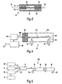
Figure 2 shows the hydraulic connections between thesensor arrangement 14 and thevalve 15. It will be noted that the ports P1 and P2 of the sensor arrangement are in communication with thehydraulic passage 27 betweeninlet 18 andoutlet 19. Anorifice plate 20 is located inpassage 27 between ports P1 and P2. - In one preferred arrangement a 150mW laser source emitting an 810nm peak wavelength uses a 50:50 multiple mode
optical fibre coupler 12. One output end of the coupler is connected to multimode optical fibre Bragg gratings (mm-FBGs) which are used for differential pressure sensing and temperature sensing. The other end (at the input side) of the optical fibre coupler is connected to an optical spectrum analyser. - In another preferred arrangement the
optical source 11 is an SLD 5mW, L3302-01 leaser from Hamamatsu emitting an 845nm peak wavelength. The optical power is launched into a 50:50 single modeoptical fibre coupler 12. Two output ends of the coupler are connected to optical fibre Bragg gratings (FBGs) which are used on a diaphragm means of the valve arrangement. Again, the other end (at the input side) of the optical fibre coupler is connected to an optical spectrum analyser (e.g. an Anritsu model MS99A, resolution 0.1nm). - The
optical fibre 13 is used to channel the sensing information fromsensors 14 in the opposite direction to the power supplied bysource 11. The information is channelled by fibre optic coupler orbeam splitter 12 from the main optical fibre via a separateoptical path 22 into an optical signal processor andmonitoring unit 16. Theunit 16 detects and converts the optical signal sent reflected from the sensors in the system to electronic information. The electrical information is then adapted and supplied to afurther unit 17 including a signal processor, a control panel, a user interface and a display unit. The adapted information is supplied to a control panel display. A control link fromunit 17 to thelaser 11 is indicated bynumeral 32. - The
optical fibre sensors 14 are used for sensing the PBL valve operation and allow most of the optical power to pass through to the PBL valve oractuator 15. Thesensors 14 comprise multimode fibre Bragg gratings (MM-FBGs) to sense the hydraulic flowrate, hydraulic pressure and fluid temperature in the hydraulic PBL valve system. In particular, one MM-FBG sensor 41 for strain is mounted between twodiaphragms 42,Figure 3 , to sense the differential pressure proportional to flow-rate through thePBL valve 15. The second MM-FBG sensor 43 is incorporated as a temperature reference and compensates the differential pressure (DP) based flow sensor. The components are mounted in ahousing 44. Thesensor 43 is located so as not to be affected by movements of thediaphragms 42. - The temperature sensing MM-FBG, pressure sensing MM-FBG and PBL valve are connected in series through the same optical
power transmission line same fibre waveguide 13 in the form of differential optical wavelength shifts. To detect the information, theunit 16 employs a wavelength demodulator to process the signals. The temperature information is also extracted. Wavelength division modulation (WDM) permits the strain and temperature signals to be extracted separately. -
Figure 4 shows an opticalpower valve arrangement 15 for hydraulic or pneumatic application, which is used to open and close a power-by-light valve. The arrangement comprises a piezoelectric multilayer orbimorph bender element 151, anelastomer blocking plate 152, aninlet nozzle 18, anoutlet nozzle 19 and a valve case orhousing 154. The valve is driven by electrical power, which is converted from optical power by aphotovoltaic converter 155 and DC-DC converter 156. The optical power output from thesensor 14 is fed into the photovoltaic converter 155 to convert into electrical power to driveelement 151 viaelectrical leads 160 which are connected to the fixedclamp end 161 ofelement 151. - A preferred
hydraulic valve arrangement 15 has an operating pressure of greater than 950kpa. - In the
valve arrangement 15, theorifice plate 20,Figure 2 , is used to restrict the fluid flow and cause a pressure drop across itself. Thethin plate diaphragms 42 are strained by applying this differential pressure to them. In an alternative arrangement, asingle FBG 41 may be mounted on asingle diaphragm 42, which is arranged such that the radial strain on the diaphragm surface is related to the applied pressure. The strain is transformed into optical information by using the optical fibre Bragg grating 41 mounted on the diaphragm(s) 42. Thesecond grating 43 is for temperature measurement and temperature compensation. The differential wavelength shift between the reflected signals from the two gratings provides a measurement of the fluid flow-rate.
Temperature variation causes the variation in the reflected wavelengths to be the same and therefore there is no change in differential wavelength (assuming perfect symmetry). Typical operating characteristics are a fluid flow-rate between 0-800cm3/s at a pressure of 50 Bar and temperature range of -4°C to 160°C, preferably 25°C to 75°C. - To manufacture preferred sensors, Bragg gratings are fabricated on multimode or single mode silica optical fibre. The output ends of each FBG sensor are connected directly to the valve to supply it with power.
- The DP sensor is connected to the differential pressure across the orifice plate.
- The above system is especially suitable for long transmission lines, typically about 5km, thus permitting remote control of the
valve 15. The use of wavelength modulation and demodulation is especially suitable for long distance applications. In addition, the system can resist harsh environments since the actuator in the valve is capable of operating in high temperatures. The actuator also has the advantage of relatively low power consumption. - The use of multimode fibre as the
line 13 allows relatively high levels of power to be transmitted, over shorter distances, whereas single mode fibre is generally preferred for use over longer distances. - The system is self-contained in that the
source 11 generates light to operatevalve 15 and all the sensors in the system. The optical power attenuation associated with the sensors is small in comparison with the power passing through to actuate thevalve 15. In particular, thesensors 14 pass the optical power directly to thevalve 15 without any coupler or splitter between them. Thus, the need is eliminated for complicated and unreliable optical assemblies at the remote end, ie adjacent tovalve 15. - The optical control loop utilises the same fibre for the majority of the transmission line where power and sensing signals travel in opposite directions. This control system can be operated without using optical fibre couplers or beam splitters at the remote end. Using a single fibre optic transmission line reduces costs, complexity, maintenance and allows easier fibre deployment.
- Variation in optical power levels to the
valve 15 can be used to vary the flow rate through the valve. Variation of flow rate through thevalve 15 can be detected using this system. Power levels to the valve are controlled using pulse width modulation to the valve or by the power setting for continuous wave emission from the light source. - Various modifications can be made to the above-described arrangement. For example the
optical source 11 may be an electrical light source or a semiconductor light source, white light, Light Emitting Diode (LED), Super Luminescent Diode (SLD), Edge-emitting LED (ELED), Laser Diode (LD) or Vertical Cavity Surface Emitting Laser Diode (VCSEL). Thetransmission line 13 may be multimode or single-mode optical fibres or other forms of optical waveguide. The same specification is used for the coupler/splitter 12 as for theoptical fibre 13. Alternatively, the beam splitter orcombiner 12 may be a cube glass beam splitter/combiner, angle glass, wavelength division multiplexing/demultiplexing (WDM/DWDM) coupler, silica-based buried channel waveguides coupler or optical couplers/splitters. - The actuator in the
valve 15 may be piezoelectric, ferroelectric, electromagnetic, photostrictive, a shape memory alloy or electrostatic. The actuator utilises the extremely small amounts of power supplied to operate effectively. - The components of
sensors 14 and actuator/valve 15 may be combined or separated as desired. - Instead of FBGs,
sensors 14 may employ the techniques of microbending, Fabry-Perot sensing, or Rayleigh or Brillouin scattering. - The optical monitoring and processing unit may include an optical spectrum analyser, a CCD array grating, tuneable filter, a scanning filter, an optical interferometer, an optical wavelength edge detector and an optical power ratio detector. However, only a single detector may be provided.
- The electronic processing can be microprocessor based or micro-controller based. Software can also be adapted for closed-loop feedback control of the
light source 11. - The optically powered actuator system of
Figure 1 may be modified to employ more than one light source for distributed sensors. ThusFigure 5 shows amonitoring system 110 with alaser source 11 and a wider bandwidth superluminescent diode 111 for the flow and temperature sensors. A 1 x Z bidirectionalfibre optic coupler 12 is employed. - The second
optical source 111 can be used to monitor when the optical fibre is broken. Thelaser source 11 is interlocked with the second source monitoring arrangement so that the laser is turned off for safety reasons if a broken fibre is detected. - Again, the
optical fibre 13 in the system can utilise either multimode or single mode optical fibre. A multimode fibre is the most suitable for the short distance system (<5km), because it is easy to couple to optical sources and inexpensive components. A single mode optical fibre is preferred when the system distance is over 5km, because the single mode fibre has a very low attenuation compared to the multimode fibre. - Also, as in the embodiment of
Figure 1 , an optical fibre based flow sensor or flowswitch 14 ofFigure 5 employs wavelength-based modulation and it allows the optical power to pass into the actuator unit ofvalve 15. For example, a differentialpressure flow sensor 14 can use an optical fibre Bragg grating in either single mode or multimode. - The optical signals from both
light sources sensor 14. The laser power passing through theFBG sensors 14 into the actuator and the optical power from secondlight source 111 is reflected back by the FBGs. The reflected signal from the FBGs is wavelength modulated and is transmitted along the sameoptical fibre 13 and is fed intosignal monitoring unit 16 andprocessor unit 17. Whereas prior art techniques, such as that disclosed inU.S. 5,848,204 use multimode FBGs in extrinsic mode for strain measurement based upon microbending and mode losses, the present technique is based upon intrinsic multimode FBGs, which offer simpler design, lower cost and better performance. Use in the "extrinsic" mode means use for reflection only, whereas use in the "intrinsic" mode means use for sensing in addition to reflection. -
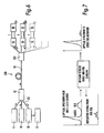
Figure 6 shows a modifiedmonitoring system 210 in which, by using anoptical coupler 212, the actuator arrangement may comprise a multiplexed plurality of sensor/valve combinations -
Figure 7 indicates the spectra of the input and output signals to and from thesensors 14. With a flow passing through theorifice plate 20, a differential pressure is produced and the MM-FBG 41 located between thediaphragms 42 is strained. The FBG reflected signal wavelength is shifted proportional to the applied strain. The amount of wavelength shift is related to the applied pressure and flow rate and can be monitored and processed byunits - Various monitoring schemes can be used by the optical signal processor and
monitoring unit unit 17 could be: using the centroid of the MM-FBG spectra, fuzzy logic, artificial neural networks, and/or correlation. For example, auto-correlation and cross-correlation can be used to analyse the data from the MM-FBG 41 and they can be completed in less than 1 second. The cross-correlation, r12(n) between two data sequences, each containing N data points, can be written as:
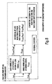
where x1(n) is the first data sequence and x2(n) the second data sequence. - For the strain measurement the MM-FBG spectra (scanned by an optical spectrum analyser) at zero strain are used to provide a reference pattern εref. The raw reference data is stored in a computer memory and is processed by the auto-correlation method. The output from the auto-correlation is used as the correlation strain reference Cεref, and this is also saved in computer memory. The new scanning data is processed again after the strain has been varied. The applied strain scanning data εscan is compared with the correlation strain reference Cεref. The distance between maximum points of each result, Cεscan(nmax) - Cεref(nmax) (where nmax is the data index point at maximum value of a correlation result), can be converted into MM-FBG wavelength shift information. A signal processing block diagram is shown in
Figure 8 . - As can be seen in
Figure 9 , the reference signal is scanned and saved in the PC memory and then the raw signal is measured (Figure 9a ). In order to establish the amount of wavelength shift, correlation signal processing (Figure 9b ) is used to evaluate the maximum correlation points between reference and measured signals. The difference of the position of the highest peaks form the two output signals obtained from the correlation process is then converted back to wavelength shift of reflection spectra. - The features and modifications of the embodiments of
Figures 1 and5 may be interchanged as desired. Thesecond source 111 may be any of the types of light source given above. - The arrangement disclosed in
Figure 5 allows the use of two sensors in series and greater sensitivity. The use of more than one light sources increases the optical bandwidth and hence improves the resolution of the or each sensor or allows an increase in the number of sensors used, or both increases resolution and the number of sensors that can be used. - The use of a 1xZ coupler 12 (with Z greater than or equal to 3) allows greater sensitivity, use of more sensors and/or interlock within a single control system. The use of a 1x Z coupler also allows the use of many actuators and/or valves at the remote end (15).
- Instead of a hydraulic valve, the above-described systems can be used in conjunction with a wide range of control elements in pneumatic, gas powered or other control systems. Typical applications include the aircraft, petrochemical, oil and gas exploration industries and use in fuel system applications. The advantages of arrangements according to the present invention in these contexts include intrinsic safety in hazardous environments, low attenuation, immunity from electromagnetic interference, cable weight and ease of deployment. Moreover, arrangements according to the present invention provide feedback-sensing information using the same optical power transmission fibre without using any coupler or beam splitter at the remote harsh environment end.
- Instead of being both powered and controlled optically, the actuator may be powered or controlled optically with the other function being effected in some other way, e.g. electrically, by electromagnetic induction, radio waves etc.
- The term "optical" as used herein embraces infra-red, ultra-violet and other non-visible electromagnetic wavelengths.
Claims (15)
- A monitoring system (10, 110, 210), for an optically powered and/or controlled actuator arrangement (14, 15) comprising an optical path (13) arranged to be connected between at least one optical source (11, 111) and the actuator arrangement for supplying power and/or control information thereto, the actuator arrangement including means for converting the optical power and/or control information, characterised in that the actuator arrangement (14, 15) further comprises means (14) for sensing the operation thereof and providing an optical data output back through said optical path (13) and in that means (16, 17) are connected to the optical path to monitor the output of said sensing means (14).
- A monitoring system according to claim 1, wherein the sensing means (14) is also operated by the optical source (11).
- A monitoring system according to claim 1 or 2, wherein the sensing means (14) comprises one or more fibre Bragg gratings (41, 43).
- A monitoring system according to claim 3, wherein a differential pressure of the actuator arrangement is sensed by an arrangement incorporating a fibre Bragg grating (41) located adjacent to at least one diaphragm (42).
- A monitoring system according to claim 4, wherein the fibre Bragg grating (41) is mounted between two diaphragms (42) arranged to be exposed to different pressures.
- A monitoring system according to any of claims 3 to 5, wherein at least one fibre Bragg grating (43) is provided for sensing the temperature.
- A monitoring system according to any preceding claim comprising at least two optical sources (11, 111), a first (11) of which is used for supplying power and/or control information, and a second (111) of which is used to detect interruption of the optical path (13) and is arranged to turn off the first source (11) in the event of such interruption.
- A monitoring system according to claim 7, wherein the first optical source (11) is a laser.
- A monitoring system according to any preceding claim wherein the monitoring means (16, 17) includes an optical spectrum analyser.
- A monitoring system according to any preceding claim comprising an optical coupler or beam splitter (12) located in the optical path.
- A monitoring system according to any preceding claim, wherein the output of the sources (11, 111) is controlled by a signal (32) from the monitoring means (16, 17).
- A monitoring system according to any preceding claim, wherein the actuator arrangement (14, 15) is at a location remote from the optical source (11, 111).
- A monitoring system according to any preceding claim, wherein the actuator arrangement (15, 15) is multiplexed.
- A method of using one or more light sources (11, 111) at a first end of an optical path (13) for powering and/or controlling a valve or actuator (15) at a second end of the optical path characterised in that light from the source(s) (11, 111) is used to interact with one or more sensors (14), at or adjacent the second end of the optical path, to produce sensing signals, and in that the method further comprises detecting the sensing signals at or adjacent the first end of the optical path.
- A detection device (14) comprising at least one fibre Bragg grating (41) for detecting movement of an adjacent diaphragm means (42) characterised in that the diaphragm means comprises two generally parallel diaphragms (42) and the grating (41) is located therebetween.
Applications Claiming Priority (3)
| Application Number | Priority Date | Filing Date | Title |
|---|---|---|---|
| GBGB0021075.7A GB0021075D0 (en) | 2000-08-25 | 2000-08-25 | Optically powered acutuator system |
| GB0021075 | 2000-08-25 | ||
| PCT/GB2001/003803 WO2002016780A2 (en) | 2000-08-25 | 2001-08-23 | Monitoring optically powered actuators |
Publications (2)
| Publication Number | Publication Date |
|---|---|
| EP1325284A2 EP1325284A2 (en) | 2003-07-09 |
| EP1325284B1 true EP1325284B1 (en) | 2010-03-31 |
Family
ID=9898377
Family Applications (1)
| Application Number | Title | Priority Date | Filing Date |
|---|---|---|---|
| EP01963138A Expired - Lifetime EP1325284B1 (en) | 2000-08-25 | 2001-08-23 | Monitoring optically powered actuators |
Country Status (7)
| Country | Link |
|---|---|
| US (1) | US7157691B2 (en) |
| EP (1) | EP1325284B1 (en) |
| AT (1) | ATE462957T1 (en) |
| AU (2) | AU2001284172B2 (en) |
| DE (1) | DE60141698D1 (en) |
| GB (1) | GB0021075D0 (en) |
| WO (1) | WO2002016780A2 (en) |
Cited By (1)
| Publication number | Priority date | Publication date | Assignee | Title |
|---|---|---|---|---|
| CN105865499A (en) * | 2016-04-05 | 2016-08-17 | 江苏道亿智能科技有限公司 | White-light interference sensor |
Families Citing this family (8)
| Publication number | Priority date | Publication date | Assignee | Title |
|---|---|---|---|---|
| US7641395B2 (en) * | 2004-06-22 | 2010-01-05 | Halliburton Energy Serives, Inc. | Fiber optic splice housing and integral dry mate connector system |
| US7580323B2 (en) * | 2005-10-21 | 2009-08-25 | The United States Of America As Represented By The Administrator Of The National Aeronautics And Space Adninistration | Tunable optical assembly with vibration dampening |
| SA08290691B1 (en) | 2007-10-31 | 2012-02-22 | شل انترناشيونال ريسيرش ماتشابيج بى . فى | Pressure Sensor Assembly and Method of Using the Assembly |
| US8941821B2 (en) * | 2009-03-18 | 2015-01-27 | Schlumberger Technology Corporation | System and method for uniform and localized wall thickness measurement using fiber optic sensors |
| IL224301A0 (en) * | 2013-01-17 | 2013-06-27 | Rafael Advanced Defense Sys | A novel mode division multiplexing optical link |
| CN111197478A (en) * | 2018-10-30 | 2020-05-26 | 中石化石油工程技术服务有限公司 | Optical fiber differential pressure flow logging system and logging method thereof |
| US11821535B2 (en) * | 2020-12-18 | 2023-11-21 | The Boeing Company | Shape memory alloy control elements for hydraulic valves |
| KR20250174974A (en) * | 2023-04-25 | 2025-12-15 | 램 리써치 코포레이션 | Vibration-based health monitoring system for valves in gas delivery systems |
Family Cites Families (11)
| Publication number | Priority date | Publication date | Assignee | Title |
|---|---|---|---|---|
| US4268116A (en) * | 1979-10-26 | 1981-05-19 | Optelecom Incorporated | Method and apparatus for radiant energy modulation in optical fibers |
| US5136603A (en) * | 1991-04-29 | 1992-08-04 | At&T Bell Laboratories | Self-monitoring semiconductor laser device |
| US5709245A (en) | 1994-09-23 | 1998-01-20 | The Boeing Company | Optically controlled actuator |
| US5584319A (en) * | 1995-07-24 | 1996-12-17 | J. M. Cholin Consultants, Inc. | Electro-optical valve-status supervision switch circuit for fire protection |
| US5848204A (en) | 1995-09-08 | 1998-12-08 | California State University-Fullerton | Fiber devices and sensors based on multimode fiber Bragg gratings |
| US6218661B1 (en) * | 1996-09-09 | 2001-04-17 | Schlumberger Technology Corporation | Methods and apparatus for mechanically enhancing the sensitivity of transversely loaded fiber optic sensors |
| US5892860A (en) * | 1997-01-21 | 1999-04-06 | Cidra Corporation | Multi-parameter fiber optic sensor for use in harsh environments |
| US6056436A (en) * | 1997-02-20 | 2000-05-02 | University Of Maryland | Simultaneous measurement of temperature and strain using optical sensors |
| US5986749A (en) * | 1997-09-19 | 1999-11-16 | Cidra Corporation | Fiber optic sensing system |
| US6370300B1 (en) * | 1999-02-18 | 2002-04-09 | Lucent Technologies Inc. | Optical communication system incorporating automatic dispersion compensation modules |
| US6739154B2 (en) * | 2001-04-24 | 2004-05-25 | Corning Incorporated | Method for manufacturing optical gratings |
-
2000
- 2000-08-25 GB GBGB0021075.7A patent/GB0021075D0/en not_active Ceased
-
2001
- 2001-08-23 WO PCT/GB2001/003803 patent/WO2002016780A2/en not_active Ceased
- 2001-08-23 AU AU2001284172A patent/AU2001284172B2/en not_active Ceased
- 2001-08-23 EP EP01963138A patent/EP1325284B1/en not_active Expired - Lifetime
- 2001-08-23 AT AT01963138T patent/ATE462957T1/en not_active IP Right Cessation
- 2001-08-23 AU AU8417201A patent/AU8417201A/en active Pending
- 2001-08-23 DE DE60141698T patent/DE60141698D1/en not_active Expired - Lifetime
- 2001-08-23 US US10/362,863 patent/US7157691B2/en not_active Expired - Fee Related
Cited By (1)
| Publication number | Priority date | Publication date | Assignee | Title |
|---|---|---|---|---|
| CN105865499A (en) * | 2016-04-05 | 2016-08-17 | 江苏道亿智能科技有限公司 | White-light interference sensor |
Also Published As
| Publication number | Publication date |
|---|---|
| US7157691B2 (en) | 2007-01-02 |
| EP1325284A2 (en) | 2003-07-09 |
| WO2002016780A2 (en) | 2002-02-28 |
| AU2001284172B2 (en) | 2007-05-17 |
| US20040036005A1 (en) | 2004-02-26 |
| ATE462957T1 (en) | 2010-04-15 |
| GB0021075D0 (en) | 2000-10-11 |
| AU8417201A (en) | 2002-03-04 |
| WO2002016780A3 (en) | 2003-05-08 |
| DE60141698D1 (en) | 2010-05-12 |
Similar Documents
| Publication | Publication Date | Title |
|---|---|---|
| US5426297A (en) | Multiplexed Bragg grating sensors | |
| EP1012553B1 (en) | High sensitivity fiber optic pressure sensor for use in harsh environments | |
| CN102119323B (en) | Fiber-optic acoustic sensor system and method using push-pull dual-wavelength Fabry-Perot sensor | |
| US5410404A (en) | Fiber grating-based detection system for wavelength encoded fiber sensors | |
| EP0954743B1 (en) | Multiparameter fiber optic sensor for use in harsh environments | |
| US6271766B1 (en) | Distributed selectable latent fiber optic sensors | |
| EP1203211B1 (en) | Method and device for fibre-optical measuring systems | |
| US6886365B2 (en) | Fiber optic Fabry-Perot interferometer and associated methods | |
| US7157691B2 (en) | Monitoring optically powered actuators | |
| US20040113055A1 (en) | Sensors system and method incorporating fibre bragg gratings | |
| AU2001284172A1 (en) | Monitoring optically powered actuators | |
| EP1630527B1 (en) | Optical displacement transducer, displacement measurement system and method | |
| US6321001B1 (en) | Wavelength division multiplexed optical communication system | |
| GB2268581A (en) | Optical fibre diffraction grating sensor | |
| US8973445B2 (en) | Multi-mode holographic pressure sensor | |
| JP2003132772A (en) | Motion detection sensor, photodetector and sensor system | |
| Kersey | Multiplexed Bragg grating fiber sensors | |
| RU77420U1 (en) | UNIVERSAL FIBER OPTICAL MODULAR TELEMETRIC COMPLEX, RECORDING MODULE, SENSOR HEAD AND OPTICAL CHANNEL EXTENSION MODULE | |
| KR101975521B1 (en) | Optical fiber interrogator using wavelength variable optical device | |
| Senior et al. | Single LED based dual wavelength referenced optical fibre sensor system using intensity modulation | |
| Chang et al. | Interrogating a fiber Bragg grating vibration sensor by narrow line width light | |
| US11163105B1 (en) | System for optical sensing | |
| Senior et al. | Referenced intensity-modulated optical fiber sensor system for measuring linear displacement | |
| Hale et al. | Optical Fibre Systems For Offshore Monitoring And Control | |
| Murtaza et al. | Intensity modulated optical fibre sensor system for measuring up to 20 mm of linear displacement |
Legal Events
| Date | Code | Title | Description |
|---|---|---|---|
| PUAI | Public reference made under article 153(3) epc to a published international application that has entered the european phase |
Free format text: ORIGINAL CODE: 0009012 |
|
| 17P | Request for examination filed |
Effective date: 20030324 |
|
| AK | Designated contracting states |
Designated state(s): AT BE CH CY DE DK ES FI FR GB GR IE IT LI LU MC NL PT SE TR |
|
| AX | Request for extension of the european patent |
Extension state: AL LT LV MK RO SI |
|
| RAP1 | Party data changed (applicant data changed or rights of an application transferred) |
Owner name: FR-HITEMP LIMITED |
|
| GRAP | Despatch of communication of intention to grant a patent |
Free format text: ORIGINAL CODE: EPIDOSNIGR1 |
|
| RAP1 | Party data changed (applicant data changed or rights of an application transferred) |
Owner name: EATON AEROSPACE LIMITED |
|
| GRAS | Grant fee paid |
Free format text: ORIGINAL CODE: EPIDOSNIGR3 |
|
| GRAA | (expected) grant |
Free format text: ORIGINAL CODE: 0009210 |
|
| AK | Designated contracting states |
Kind code of ref document: B1 Designated state(s): AT BE CH CY DE DK ES FI FR GB GR IE IT LI LU MC NL PT SE TR |
|
| REG | Reference to a national code |
Ref country code: GB Ref legal event code: FG4D Ref country code: CH Ref legal event code: EP |
|
| REG | Reference to a national code |
Ref country code: IE Ref legal event code: FG4D |
|
| REF | Corresponds to: |
Ref document number: 60141698 Country of ref document: DE Date of ref document: 20100512 Kind code of ref document: P |
|
| REG | Reference to a national code |
Ref country code: NL Ref legal event code: VDEP Effective date: 20100331 |
|
| PG25 | Lapsed in a contracting state [announced via postgrant information from national office to epo] |
Ref country code: FI Free format text: LAPSE BECAUSE OF FAILURE TO SUBMIT A TRANSLATION OF THE DESCRIPTION OR TO PAY THE FEE WITHIN THE PRESCRIBED TIME-LIMIT Effective date: 20100331 Ref country code: AT Free format text: LAPSE BECAUSE OF FAILURE TO SUBMIT A TRANSLATION OF THE DESCRIPTION OR TO PAY THE FEE WITHIN THE PRESCRIBED TIME-LIMIT Effective date: 20100331 |
|
| PG25 | Lapsed in a contracting state [announced via postgrant information from national office to epo] |
Ref country code: CY Free format text: LAPSE BECAUSE OF FAILURE TO SUBMIT A TRANSLATION OF THE DESCRIPTION OR TO PAY THE FEE WITHIN THE PRESCRIBED TIME-LIMIT Effective date: 20100331 Ref country code: NL Free format text: LAPSE BECAUSE OF FAILURE TO SUBMIT A TRANSLATION OF THE DESCRIPTION OR TO PAY THE FEE WITHIN THE PRESCRIBED TIME-LIMIT Effective date: 20100331 Ref country code: SE Free format text: LAPSE BECAUSE OF FAILURE TO SUBMIT A TRANSLATION OF THE DESCRIPTION OR TO PAY THE FEE WITHIN THE PRESCRIBED TIME-LIMIT Effective date: 20100331 Ref country code: ES Free format text: LAPSE BECAUSE OF FAILURE TO SUBMIT A TRANSLATION OF THE DESCRIPTION OR TO PAY THE FEE WITHIN THE PRESCRIBED TIME-LIMIT Effective date: 20100712 Ref country code: BE Free format text: LAPSE BECAUSE OF FAILURE TO SUBMIT A TRANSLATION OF THE DESCRIPTION OR TO PAY THE FEE WITHIN THE PRESCRIBED TIME-LIMIT Effective date: 20100331 |
|
| PG25 | Lapsed in a contracting state [announced via postgrant information from national office to epo] |
Ref country code: DK Free format text: LAPSE BECAUSE OF FAILURE TO SUBMIT A TRANSLATION OF THE DESCRIPTION OR TO PAY THE FEE WITHIN THE PRESCRIBED TIME-LIMIT Effective date: 20100331 Ref country code: PT Free format text: LAPSE BECAUSE OF FAILURE TO SUBMIT A TRANSLATION OF THE DESCRIPTION OR TO PAY THE FEE WITHIN THE PRESCRIBED TIME-LIMIT Effective date: 20100802 |
|
| PLBE | No opposition filed within time limit |
Free format text: ORIGINAL CODE: 0009261 |
|
| STAA | Information on the status of an ep patent application or granted ep patent |
Free format text: STATUS: NO OPPOSITION FILED WITHIN TIME LIMIT |
|
| 26N | No opposition filed |
Effective date: 20110104 |
|
| PG25 | Lapsed in a contracting state [announced via postgrant information from national office to epo] |
Ref country code: IT Free format text: LAPSE BECAUSE OF FAILURE TO SUBMIT A TRANSLATION OF THE DESCRIPTION OR TO PAY THE FEE WITHIN THE PRESCRIBED TIME-LIMIT Effective date: 20100331 |
|
| PG25 | Lapsed in a contracting state [announced via postgrant information from national office to epo] |
Ref country code: IE Free format text: LAPSE BECAUSE OF NON-PAYMENT OF DUE FEES Effective date: 20100823 |
|
| PG25 | Lapsed in a contracting state [announced via postgrant information from national office to epo] |
Ref country code: TR Free format text: LAPSE BECAUSE OF FAILURE TO SUBMIT A TRANSLATION OF THE DESCRIPTION OR TO PAY THE FEE WITHIN THE PRESCRIBED TIME-LIMIT Effective date: 20100331 |
|
| PGFP | Annual fee paid to national office [announced via postgrant information from national office to epo] |
Ref country code: MC Payment date: 20130729 Year of fee payment: 13 Ref country code: LU Payment date: 20130902 Year of fee payment: 13 |
|
| REG | Reference to a national code |
Ref country code: CH Ref legal event code: PFA Owner name: EATON LIMITED, GB Free format text: FORMER OWNER: EATON AEROSPACE LIMITED, GB |
|
| REG | Reference to a national code |
Ref country code: GB Ref legal event code: 732E Free format text: REGISTERED BETWEEN 20140424 AND 20140430 |
|
| REG | Reference to a national code |
Ref country code: DE Ref legal event code: R081 Ref document number: 60141698 Country of ref document: DE Owner name: EATON LTD., GB Free format text: FORMER OWNER: EATON AEROSPACE LTD., TITCHFIELD, GB Effective date: 20140506 Ref country code: DE Ref legal event code: R081 Ref document number: 60141698 Country of ref document: DE Owner name: EATON LTD., TITCHFIELD, GB Free format text: FORMER OWNER: EATON AEROSPACE LTD., TITCHFIELD, HAMPSHIRE, GB Effective date: 20140506 |
|
| REG | Reference to a national code |
Ref country code: FR Ref legal event code: TP Owner name: EATON LIMITED, GB Effective date: 20140715 |
|
| PG25 | Lapsed in a contracting state [announced via postgrant information from national office to epo] |
Ref country code: GR Free format text: LAPSE BECAUSE OF FAILURE TO SUBMIT A TRANSLATION OF THE DESCRIPTION OR TO PAY THE FEE WITHIN THE PRESCRIBED TIME-LIMIT Effective date: 20100331 |
|
| PG25 | Lapsed in a contracting state [announced via postgrant information from national office to epo] |
Ref country code: LU Free format text: LAPSE BECAUSE OF NON-PAYMENT OF DUE FEES Effective date: 20140823 Ref country code: MC Free format text: LAPSE BECAUSE OF NON-PAYMENT OF DUE FEES Effective date: 20140901 |
|
| REG | Reference to a national code |
Ref country code: FR Ref legal event code: PLFP Year of fee payment: 15 |
|
| REG | Reference to a national code |
Ref country code: FR Ref legal event code: PLFP Year of fee payment: 16 |
|
| REG | Reference to a national code |
Ref country code: FR Ref legal event code: PLFP Year of fee payment: 17 |
|
| PGFP | Annual fee paid to national office [announced via postgrant information from national office to epo] |
Ref country code: CH Payment date: 20170725 Year of fee payment: 17 Ref country code: GB Payment date: 20170725 Year of fee payment: 17 Ref country code: DE Payment date: 20170825 Year of fee payment: 17 Ref country code: FR Payment date: 20170720 Year of fee payment: 17 |
|
| REG | Reference to a national code |
Ref country code: GB Ref legal event code: 732E Free format text: REGISTERED BETWEEN 20181203 AND 20181205 |
|
| REG | Reference to a national code |
Ref country code: DE Ref legal event code: R081 Ref document number: 60141698 Country of ref document: DE Owner name: EATON INTELLIGENT POWER LIMITED, IE Free format text: FORMER OWNER: EATON LTD., TITCHFIELD, HAMPSHIRE, GB |
|
| REG | Reference to a national code |
Ref country code: DE Ref legal event code: R119 Ref document number: 60141698 Country of ref document: DE |
|
| REG | Reference to a national code |
Ref country code: CH Ref legal event code: PL |
|
| GBPC | Gb: european patent ceased through non-payment of renewal fee |
Effective date: 20180823 |
|
| PG25 | Lapsed in a contracting state [announced via postgrant information from national office to epo] |
Ref country code: CH Free format text: LAPSE BECAUSE OF NON-PAYMENT OF DUE FEES Effective date: 20180831 Ref country code: LI Free format text: LAPSE BECAUSE OF NON-PAYMENT OF DUE FEES Effective date: 20180831 |
|
| PG25 | Lapsed in a contracting state [announced via postgrant information from national office to epo] |
Ref country code: DE Free format text: LAPSE BECAUSE OF NON-PAYMENT OF DUE FEES Effective date: 20190301 |
|
| PG25 | Lapsed in a contracting state [announced via postgrant information from national office to epo] |
Ref country code: FR Free format text: LAPSE BECAUSE OF NON-PAYMENT OF DUE FEES Effective date: 20180831 |
|
| PG25 | Lapsed in a contracting state [announced via postgrant information from national office to epo] |
Ref country code: GB Free format text: LAPSE BECAUSE OF NON-PAYMENT OF DUE FEES Effective date: 20180823 |