EP1324799B1 - Guidewire having a marker segment for length assessment - Google Patents
Guidewire having a marker segment for length assessment Download PDFInfo
- Publication number
- EP1324799B1 EP1324799B1 EP01981391A EP01981391A EP1324799B1 EP 1324799 B1 EP1324799 B1 EP 1324799B1 EP 01981391 A EP01981391 A EP 01981391A EP 01981391 A EP01981391 A EP 01981391A EP 1324799 B1 EP1324799 B1 EP 1324799B1
- Authority
- EP
- European Patent Office
- Prior art keywords
- length
- guidewire
- core wire
- accordance
- markers
- Prior art date
- Legal status (The legal status is an assumption and is not a legal conclusion. Google has not performed a legal analysis and makes no representation as to the accuracy of the status listed.)
- Expired - Lifetime
Links
Images
Classifications
-
- A—HUMAN NECESSITIES
- A61—MEDICAL OR VETERINARY SCIENCE; HYGIENE
- A61M—DEVICES FOR INTRODUCING MEDIA INTO, OR ONTO, THE BODY; DEVICES FOR TRANSDUCING BODY MEDIA OR FOR TAKING MEDIA FROM THE BODY; DEVICES FOR PRODUCING OR ENDING SLEEP OR STUPOR
- A61M25/00—Catheters; Hollow probes
- A61M25/01—Introducing, guiding, advancing, emplacing or holding catheters
- A61M25/09—Guide wires
-
- A—HUMAN NECESSITIES
- A61—MEDICAL OR VETERINARY SCIENCE; HYGIENE
- A61B—DIAGNOSIS; SURGERY; IDENTIFICATION
- A61B5/00—Measuring for diagnostic purposes; Identification of persons
- A61B5/103—Detecting, measuring or recording devices for testing the shape, pattern, colour, size or movement of the body or parts thereof, for diagnostic purposes
- A61B5/107—Measuring physical dimensions, e.g. size of the entire body or parts thereof
- A61B5/1076—Measuring physical dimensions, e.g. size of the entire body or parts thereof for measuring dimensions inside body cavities, e.g. using catheters
-
- A—HUMAN NECESSITIES
- A61—MEDICAL OR VETERINARY SCIENCE; HYGIENE
- A61M—DEVICES FOR INTRODUCING MEDIA INTO, OR ONTO, THE BODY; DEVICES FOR TRANSDUCING BODY MEDIA OR FOR TAKING MEDIA FROM THE BODY; DEVICES FOR PRODUCING OR ENDING SLEEP OR STUPOR
- A61M25/00—Catheters; Hollow probes
- A61M2025/0008—Catheters; Hollow probes having visible markings on its surface, i.e. visible to the naked eye, for any purpose, e.g. insertion depth markers, rotational markers or identification of type
-
- A—HUMAN NECESSITIES
- A61—MEDICAL OR VETERINARY SCIENCE; HYGIENE
- A61M—DEVICES FOR INTRODUCING MEDIA INTO, OR ONTO, THE BODY; DEVICES FOR TRANSDUCING BODY MEDIA OR FOR TAKING MEDIA FROM THE BODY; DEVICES FOR PRODUCING OR ENDING SLEEP OR STUPOR
- A61M25/00—Catheters; Hollow probes
- A61M25/01—Introducing, guiding, advancing, emplacing or holding catheters
- A61M25/09—Guide wires
- A61M2025/09058—Basic structures of guide wires
- A61M2025/09083—Basic structures of guide wires having a coil around a core
-
- A—HUMAN NECESSITIES
- A61—MEDICAL OR VETERINARY SCIENCE; HYGIENE
- A61M—DEVICES FOR INTRODUCING MEDIA INTO, OR ONTO, THE BODY; DEVICES FOR TRANSDUCING BODY MEDIA OR FOR TAKING MEDIA FROM THE BODY; DEVICES FOR PRODUCING OR ENDING SLEEP OR STUPOR
- A61M25/00—Catheters; Hollow probes
- A61M25/01—Introducing, guiding, advancing, emplacing or holding catheters
- A61M25/09—Guide wires
- A61M2025/09166—Guide wires having radio-opaque features
Definitions
- the present invention relates to the field of guidewires for percutaneous procedures.
- the present invention relates particularly to a guidewire having a marker segment.
- Guidewires are used in a number of procedures within various conduits of the body.
- guidewires are used in percutaneous transluminal coronary angioplasty (PTCA) and other coronary procedures. This can involve insertion of the guide wire through an incision in the femoral artery near the groin, advancing the guide wire over the aortic arch, into a coronary artery, and across the lesion to be treated.
- Guidewires can be inserted directly into the vasculature or within a guide catheter. The distal end of the guidewire ultimately lies directly within the vasculature.
- the length of the device, or length of a portion of the device advanced over the guidewire can be important.
- the length of the dilatation balloon is preferably sufficiently long to dilate a coronary lesion without repositioning the angioplasty catheter or exchanging the catheter for a second angioplasty catheter.
- the placement of a stent often follows angioplasty.
- the length of the stent is preferably sufficient to support the length of the lesion.
- the EP 0 771 572 A1 discloses a guidewire with radiopaque markers.
- a guidewire comprises a tip section including a core wire including a first tapered portion, a reduced-in-diameter portion, a second tapered portion and a rod end portion, two or more highly radiopaque annular marker bands being received on the core wire between the first tapered portion and the rod end portion and precisely spaced apart on the core wire by one or more plastic tubing segments, and an outer sleeve covering said marker bands and tubing segments.
- a guidewire that can be used to easily estimate the length of anatomic or artificial structures percutaneously. Further, what is desirable is a guidewire having a one or more easily viewable markers with a predetermined distance between each marker so that the conjunction of markers provide a scale to a position that a physician can easily and accurately determine distances within a blood vessel.
- the present invention pertains to a guide wire which can be placed in a patient's vasculature or body cavity.
- the guide wire includes one or more radiopaque markers which can be visualized by fluoroscopy or the like.
- the markers are spaced apart longitudinally along the guide wire such that the markers and/or spaces between the markers can be used to make measurements of anatomical or artificial structures within the body.
- the present invention relates to a guide wire which can be placed in a patient's vasculature or body cavity, wherein the guide wire includes one or more radiopaque markers that are spaced apart longitudinally along the guide wire such that the markers and/or spaces between the markers can be used to make measurements of anatomical or artificial structures within the body.
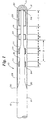
- Figure 1 is a schematic, cross-sectional view of a guide wire 10 in accordance with a preferred embodiment of the present invention.
- Guide wire 10 includes a core wire 12 having a proximal end and a distal end 11, the former not being shown.
- Guide wire 10 preferably includes an elongate core member wire 12.
- Core wire 12 may be formed in diameters and lengths appropriate to the various percutaneous procedures conducted using guide wires.
- Core wire 12 may include a proximal first diameter section 14, a more distal, lesser diameter second section 16 and a yet more distal, and lesser diameter third section 18.
- core wire 12 includes a first parabolic shaped transition portion 20 between first diameter section 14 and second section 16, and a second parabolic shaped transition portion 22 between second section 16 and third section 18.
- a rounded atraumatic tip 32 may be adhered to, soldered to or formed at the third section 18 of core wire 12.
- Surrounding the third section 18 of core wire 12 is a coil 28.
- a distal end 31 and a proximal end 30 of the coil 28 may be connected by solder, adhesive, or the like to the core wire 12.
- the coil 28 may extend proximally to a point where the thickness of core wire 12 has been transitioned to have a diameter approximately equal to the inside diameter of coil 28.
- a plurality of radiopaque members are preferably located proximal the distal end 11, including, for example, markers 24 and distal member 26.
- Markers 24 can be connected to core wire 12 by solder 34, adhesive or the like, including, for example, UV adhesive or TFE (tetrafluoroethylene) tubing.
- Core wire 12 and coil 28 are preferably formed from materials less radiopaque than markers 24 and distal member 26.
- Core wire 12 and coil 28 can be formed from, for example, stainless steel, Nitinol, Inconel®, or other bio-compatible materials known to those skilled in the art.
- Markers 24 and distal member 26 are preferably formed from substantially radiopaque material such as platinum, gold or other substantially radiopaque material. It should be understood, however, that the materials recited herein are merely exemplary and one skilled in the art would know that alternative bio-compatible materials could be advantageously used.
- Markers 24 and distal member 26 may be disposed around core member 12.
- An outer coil 28 can be disposed around core wire 14 and markers 24 and distal member 26.
- markers 24 and distal member 26 may be made of a wire coil that extend around the entire outer circumference of the core member 12. It should be understood that markers 24 and distal member 26 may be formed of a marker band that extends around the entire outer circumference of the core member 12, and the marker wire coil and/or marker band may be shaped in a variety of shapes, and may extend only partially around the core member 12.
- Markers 24 are preferably spaced a distance A from each other and/or distal member 26. Markers 24 preferably have a length B. Although spacing distances A are shown in Figure 1 as having equal lengths, this equal spacing distance is not required for all embodiments of the present invention. Additionally, although lengths B of marker bands 24 are also shown as being equal, this is also not required for every embodiment of the present invention. Distal member 26 preferably has a length C. The length C of distal member 26 is preferably equal to the sum of spacing distance A and the length B of a single marker 24. Additionally, although length C of distal member 26 is shown as being equal to the sum of spacing distance A and the length B of a single marker 24, this is not required for every embodiment of the present invention.
- the spacing distance A is a positive multiple X of marker length B, wherein the positive multiple X is not more than three.
- spacing distance A could be 15 mm where length B is 5 mm, and wherein the positive multiple X is three.
- spacing distance A could be 6 mm where length B is 3 mm, wherein the positive multiple X is two. It can be appreciated that numerous spacings A can be selected as positive multiples of three or less of length B. It again should be understood that although in a preferred embodiment, each spacing distance A is equivalent and each marker length B is equivalent as shown, for example, Figure 1, this arrangement need not be made in accordance with every embodiment of the present invention.
- the length of an anatomical or artificial structure could be measured within the body and be estimated within 3 mm.
- a structure of 3 mm or less will not be longer than the 3 mm length marker B, which under fluoroscopy will appear as a bright mark.
- a structure 6 mm long will appear when compared to 6 mm spacing distance A, as substantially equivalent in length. It can be appreciated that the space will appear dark under fluoroscopy if a series of 6 mm spacing distances A, are created between a series of 3 mm marker lengths B, and additional length measurements can then be made.
- the length of a structure greater than 6 mm long, but less than 9 mm long may be estimated by comparing the structure length to the 3 mm length B and an adjacent 6 mm spacing distance A.
- the length of a structure greater than 9 mm, but less than 12 mm long can be estimated by a comparison to the length B or two 3 mm markers and the 6 mm spacing distance A therebetween.
- additional length measurements can be made at 3 mm increments by comparing additional combinations of 3 mm marker lengths B and 6 mm spacing distances A to a structure.
- a 3 mm length B and a 6 mm spacing distance A has been used for this example, other marker lengths and spacing distances can also be used in accordance with the present invention.
- spacing distance A were 15 mm and length B were 5 mm
- the length of an anatomical or artificial structure could be measured within the body and be estimated within 5 mm.
- a structure of 5 mm or less will not be longer than the 5 mm length marker, which under fluoroscopy will appear as a bright mark.
- a structure 15 mm long will appear when compared to 15 mm spacing distance A, as substantially equivalent in length. It can be appreciated that the space will appear dark under fluoroscopy if a series of 15 mm spacing distances A, are created between a series of 5 mm marker lengths B, additional length measurements can then be made.
- the length of a structure greater than 15 mm long, but less than 20 mm long may be estimated by comparing the structure length to the 5 mm length B and an adjacent 15 mm spacing distance A.
- the length of a structure greater than 20 mm, but less than 25 mm long can be estimated by a comparison to the length B or two 5 mm markers and the 15 mm spacing distance A therebetween. It can be appreciated that although a 5 mm length B and a 15 mm spacing distance A has been used for the preferred embodiment, other marker lengths and spacing distances can also be used in accordance with the present invention.
- guide wire 10 includes three spacings A, three markers 24 and a distal member 26.
- the third marker 24 is disposed along the core wire.
- the third marker 24 has a third length that may be equal to the first and second markers 24.
- the third marker 24 may be spaced from the first member by a second spacing distance, D.
- the second spacing distance D may be a positive multiple of the marker length B. It can be appreciated that second spacing distance D may have other spatial relations to the marker length B and spacing distance A. Further, it can be appreciated that fewer or more markers 24 and spacings A can be used in accordance with the present invention.
- spacing distance D is a positive multiple X of marker length B.
- spacing distance D could be 35 mm where length B is 5 mm, and wherein the positive multiple X is seven.
- spacing distance D could be 12 mm where length B is 3 mm, wherein the positive multiple X is four. It can be appreciated that numerous spacings D can be selected as positive multiples of length B. It again should be understood that although in a preferred embodiment, each spacing distance D is a positive multiple marker length B as shown, for example, Figure 1, this arrangement need not be made in accordance with every embodiment of the present invention.
Abstract
Description
- The present invention relates to the field of guidewires for percutaneous procedures. The present invention relates particularly to a guidewire having a marker segment.
- Guidewires are used in a number of procedures within various conduits of the body. In particular, guidewires are used in percutaneous transluminal coronary angioplasty (PTCA) and other coronary procedures. This can involve insertion of the guide wire through an incision in the femoral artery near the groin, advancing the guide wire over the aortic arch, into a coronary artery, and across the lesion to be treated. Guidewires can be inserted directly into the vasculature or within a guide catheter. The distal end of the guidewire ultimately lies directly within the vasculature.
- Once the distal end of the guidewire is positioned in the vasculature, devices including catheters can be advanced into position over the guidewire and withdrawn over the guidewire. In various procedures, the length of the device, or length of a portion of the device advanced over the guidewire can be important. For example, if the guidewire is being used for angioplasty, the length of the dilatation balloon is preferably sufficiently long to dilate a coronary lesion without repositioning the angioplasty catheter or exchanging the catheter for a second angioplasty catheter. The placement of a stent often follows angioplasty. When selecting a stent for placement following angioplasty, the length of the stent is preferably sufficient to support the length of the lesion.
- The EP 0 771 572 A1 discloses a guidewire with radiopaque markers. Such a guidewire comprises a tip section including a core wire including a first tapered portion, a reduced-in-diameter portion, a second tapered portion and a rod end portion, two or more highly radiopaque annular marker bands being received on the core wire between the first tapered portion and the rod end portion and precisely spaced apart on the core wire by one or more plastic tubing segments, and an outer sleeve covering said marker bands and tubing segments.
- What is desirable and has not been provided is a guidewire that can be used to easily estimate the length of anatomic or artificial structures percutaneously. Further, what is desirable is a guidewire having a one or more easily viewable markers with a predetermined distance between each marker so that the conjunction of markers provide a scale to a position that a physician can easily and accurately determine distances within a blood vessel.
- The present invention pertains to a guide wire which can be placed in a patient's vasculature or body cavity. The guide wire includes one or more radiopaque markers which can be visualized by fluoroscopy or the like. The markers are spaced apart longitudinally along the guide wire such that the markers and/or spaces between the markers can be used to make measurements of anatomical or artificial structures within the body.
-
- Figure 1 is a cross-sectional view of a guide wire in accordance with a preferred embodiment of the present invention.
- Preferred embodiments of the present invention will be described in detail with reference to the drawings, wherein like reference numerals represent like parts and assemblies throughout the several views. This description does not limit the scope of the invention, which is limited only by the scope of the attached claims.
- In general terms, the present invention relates to a guide wire which can be placed in a patient's vasculature or body cavity, wherein the guide wire includes one or more radiopaque markers that are spaced apart longitudinally along the guide wire such that the markers and/or spaces between the markers can be used to make measurements of anatomical or artificial structures within the body.
- Figure 1 is a schematic, cross-sectional view of a
guide wire 10 in accordance with a preferred embodiment of the present invention.Guide wire 10 includes acore wire 12 having a proximal end and a distal end 11, the former not being shown.Guide wire 10 preferably includes an elongatecore member wire 12.Core wire 12 may be formed in diameters and lengths appropriate to the various percutaneous procedures conducted using guide wires.Core wire 12 may include a proximalfirst diameter section 14, a more distal, lesser diametersecond section 16 and a yet more distal, and lesser diameterthird section 18. In a preferred embodiment,core wire 12 includes a first parabolicshaped transition portion 20 betweenfirst diameter section 14 andsecond section 16, and a second parabolicshaped transition portion 22 betweensecond section 16 andthird section 18. It can be appreciated that the tapering and reducing of the diameter of a distal region ofcore wire 12 can make the distal region ofguide wire 10 more flexible to enhance steerability of the guide wire. Various combinations of core wire diameter, or cross-sectional reduction proximate distal end 11 can be made without departing from the scope of the present invention. - A rounded
atraumatic tip 32 may be adhered to, soldered to or formed at thethird section 18 ofcore wire 12. Surrounding thethird section 18 ofcore wire 12 is acoil 28. Adistal end 31 and aproximal end 30 of thecoil 28 may be connected by solder, adhesive, or the like to thecore wire 12. In a preferred embodiment, thecoil 28 may extend proximally to a point where the thickness ofcore wire 12 has been transitioned to have a diameter approximately equal to the inside diameter ofcoil 28. - A plurality of radiopaque members are preferably located proximal the distal end 11, including, for example,
markers 24 anddistal member 26.Markers 24 can be connected tocore wire 12 bysolder 34, adhesive or the like, including, for example, UV adhesive or TFE (tetrafluoroethylene) tubing. -
Core wire 12 andcoil 28 are preferably formed from materials less radiopaque thanmarkers 24 anddistal member 26.Core wire 12 andcoil 28 can be formed from, for example, stainless steel, Nitinol, Inconel®, or other bio-compatible materials known to those skilled in the art.Markers 24 anddistal member 26 are preferably formed from substantially radiopaque material such as platinum, gold or other substantially radiopaque material. It should be understood, however, that the materials recited herein are merely exemplary and one skilled in the art would know that alternative bio-compatible materials could be advantageously used. - Markers 24 and
distal member 26 may be disposed aroundcore member 12. Anouter coil 28 can be disposed aroundcore wire 14 andmarkers 24 anddistal member 26. Preferably,markers 24 anddistal member 26 may be made of a wire coil that extend around the entire outer circumference of thecore member 12. It should be understood thatmarkers 24 anddistal member 26 may be formed of a marker band that extends around the entire outer circumference of thecore member 12, and the marker wire coil and/or marker band may be shaped in a variety of shapes, and may extend only partially around thecore member 12. -
Markers 24 are preferably spaced a distance A from each other and/ordistal member 26.Markers 24 preferably have a length B. Although spacing distances A are shown in Figure 1 as having equal lengths, this equal spacing distance is not required for all embodiments of the present invention. Additionally, although lengths B ofmarker bands 24 are also shown as being equal, this is also not required for every embodiment of the present invention.Distal member 26 preferably has a length C. The length C ofdistal member 26 is preferably equal to the sum of spacing distance A and the length B of asingle marker 24. Additionally, although length C ofdistal member 26 is shown as being equal to the sum of spacing distance A and the length B of asingle marker 24, this is not required for every embodiment of the present invention. - The spacing distance A is a positive multiple X of marker length B, wherein the positive multiple X is not more than three. For example, spacing distance A could be 15 mm where length B is 5 mm, and wherein the positive multiple X is three. In yet another embodiment, spacing distance A could be 6 mm where length B is 3 mm, wherein the positive multiple X is two. It can be appreciated that numerous spacings A can be selected as positive multiples of three or less of length B. It again should be understood that although in a preferred embodiment, each spacing distance A is equivalent and each marker length B is equivalent as shown, for example, Figure 1, this arrangement need not be made in accordance with every embodiment of the present invention.
- In use as one embodiment of the invention, if spacing distance A were 6 mm and length B were 3 mm, the length of an anatomical or artificial structure could be measured within the body and be estimated within 3 mm. A structure of 3 mm or less will not be longer than the 3 mm length marker B, which under fluoroscopy will appear as a bright mark. A structure 6 mm long will appear when compared to 6 mm spacing distance A, as substantially equivalent in length. It can be appreciated that the space will appear dark under fluoroscopy if a series of 6 mm spacing distances A, are created between a series of 3 mm marker lengths B, and additional length measurements can then be made. The length of a structure greater than 6 mm long, but less than 9 mm long, for example, may be estimated by comparing the structure length to the 3 mm length B and an adjacent 6 mm spacing distance A. The length of a structure greater than 9 mm, but less than 12 mm long can be estimated by a comparison to the length B or two 3 mm markers and the 6 mm spacing distance A therebetween. It can be appreciated that additional length measurements can be made at 3 mm increments by comparing additional combinations of 3 mm marker lengths B and 6 mm spacing distances A to a structure. It can be appreciated that although a 3 mm length B and a 6 mm spacing distance A has been used for this example, other marker lengths and spacing distances can also be used in accordance with the present invention.
- In use as a preferred embodiment of the invention, if spacing distance A were 15 mm and length B were 5 mm, the length of an anatomical or artificial structure could be measured within the body and be estimated within 5 mm. A structure of 5 mm or less will not be longer than the 5 mm length marker, which under fluoroscopy will appear as a bright mark. A structure 15 mm long will appear when compared to 15 mm spacing distance A, as substantially equivalent in length. It can be appreciated that the space will appear dark under fluoroscopy if a series of 15 mm spacing distances A, are created between a series of 5 mm marker lengths B, additional length measurements can then be made. The length of a structure greater than 15 mm long, but less than 20 mm long, for example, may be estimated by comparing the structure length to the 5 mm length B and an adjacent 15 mm spacing distance A. The length of a structure greater than 20 mm, but less than 25 mm long can be estimated by a comparison to the length B or two 5 mm markers and the 15 mm spacing distance A therebetween. It can be appreciated that although a 5 mm length B and a 15 mm spacing distance A has been used for the preferred embodiment, other marker lengths and spacing distances can also be used in accordance with the present invention.
- As shown in Figure 1,
guide wire 10 includes three spacings A, threemarkers 24 and adistal member 26. Thethird marker 24 is disposed along the core wire. In a preferred embodiment, thethird marker 24 has a third length that may be equal to the first andsecond markers 24. Thethird marker 24 may be spaced from the first member by a second spacing distance, D. The second spacing distance D, may be a positive multiple of the marker length B. It can be appreciated that second spacing distance D may have other spatial relations to the marker length B and spacing distance A. Further, it can be appreciated that fewer ormore markers 24 and spacings A can be used in accordance with the present invention. - In a preferred embodiment, spacing distance D is a positive multiple X of marker length B. For example, spacing distance D could be 35 mm where length B is 5 mm, and wherein the positive multiple X is seven. In yet another embodiment, spacing distance D could be 12 mm where length B is 3 mm, wherein the positive multiple X is four. It can be appreciated that numerous spacings D can be selected as positive multiples of length B. It again should be understood that although in a preferred embodiment, each spacing distance D is a positive multiple marker length B as shown, for example, Figure 1, this arrangement need not be made in accordance with every embodiment of the present invention.
- The foregoing description of the invention has been presented for purposes of illustration and description, and is not intended to be exhaustive or to limit the invention to the precise form disclosed. The description was selected to explain the principles of the invention in various embodiments and various modifications as are suited to the particular use contemplated. It is intended that the scope of the invention not be limited by the specification, but defined by the claims set forth below:
Claims (11)
- A guidewire, comprising:an elongate core wire (12); anda first and a second substantially radiopaque members (24) disposed along the elongate core wire (12), the first radiopaque member (24) having a first length (B), and the second member (24) having a second length (B),characterized in thatthe first and second members (24) are longitudinally spaced along the elongate core wire (12) at a first spacing distance (A) which is a positive multiple X of the first length (B) or the second length (B), wherein X is not more than three.
- The guidewire in accordance with claim 1, wherein the first length (B) is equal to the second length (B).
- The guidewire in accordance with claim 1, further comprising a third substantially radiopaque member (24) disposed along the elongate core wire (12), the third member (24) having a third length (B), the third member (24) being spaced from the first member (24) by a second spacing distance (D).
- The guidewire in accordance with claim 3, wherein the second spacing distance (D) is a positive multiple X of the first length (B).
- The guidewire in accordance with claim 4, wherein the third length (B) is equal to the first length (B).
- The guide wire in accordance with claim 3, wherein a coil (28) extends around a portion of the elongate core wire (12) including the first, second and third radiopaque members (24).
- The guidewire in accordance with any of claims 3 to 6,
wherein the first, second and third members (24) being longitudinally spaced along the core wire at a first spacing distance (A) which is:(a) a positive multiple X of the first length (B), wherein X is not more than three, or(b) a positive multiple X of the second length (B), wherein X is not more than three, or(c) a positive multiple X of the third length (B), wherein X is not more than three. - The guidewire in accordance with any of claims 1 to 7, further comprising:a distal substantially radiopaque member (26) disposed along the elongate core wire (12), the distal member (26) having a length (C), the distal member (26), the first and second members (24) being longitudinally spaced along the elongate core wire (12) at a first spacing distance (A) which is:(a) a positive multiple X of the first length (B), wherein X is not more than three, or(b) a positive multiple X of the second length (B), wherein X is not more than three.
- The guidewire in accordance with claim 8, wherein the length (C) of the distal member (26) is equal to the sum of the first spacing (A) and the first length (B), and/or wherein the length (C) of the distal member (26) is equal to the sum of the first spacing (A) and the second length (B).
- The guidewire in accordance with any of the preceding claims, wherein said members (24, 26) include coils preferably of platinum.
- The guidewire in accordance with claim 10, wherein the coils of said members (24, 26) are attached to the elongate core wire (12) by a solder joint (34).
Applications Claiming Priority (5)
| Application Number | Priority Date | Filing Date | Title |
|---|---|---|---|
| US23818400P | 2000-10-05 | 2000-10-05 | |
| US238184P | 2000-10-05 | ||
| US971410 | 2001-10-04 | ||
| US09/971,410 US6620114B2 (en) | 2000-10-05 | 2001-10-04 | Guidewire having a marker segment for length assessment |
| PCT/US2001/031237 WO2002028468A2 (en) | 2000-10-05 | 2001-10-05 | Guidewire having a marker segment for length assessment |
Publications (2)
| Publication Number | Publication Date |
|---|---|
| EP1324799A2 EP1324799A2 (en) | 2003-07-09 |
| EP1324799B1 true EP1324799B1 (en) | 2006-02-22 |
Family
ID=26931410
Family Applications (1)
| Application Number | Title | Priority Date | Filing Date |
|---|---|---|---|
| EP01981391A Expired - Lifetime EP1324799B1 (en) | 2000-10-05 | 2001-10-05 | Guidewire having a marker segment for length assessment |
Country Status (9)
| Country | Link |
|---|---|
| US (1) | US6620114B2 (en) |
| EP (1) | EP1324799B1 (en) |
| JP (1) | JP2004516049A (en) |
| AT (1) | ATE318161T1 (en) |
| AU (1) | AU2002213035A1 (en) |
| CA (1) | CA2423438A1 (en) |
| DE (1) | DE60117401T2 (en) |
| ES (1) | ES2259042T3 (en) |
| WO (1) | WO2002028468A2 (en) |
Cited By (2)
| Publication number | Priority date | Publication date | Assignee | Title |
|---|---|---|---|---|
| DE102005030607A1 (en) * | 2005-06-30 | 2007-01-04 | Siemens Ag | Interventional instrument with marker element |
| EP2962718A1 (en) * | 2014-07-02 | 2016-01-06 | Asahi Intecc Co., Ltd. | Guidewire |
Families Citing this family (38)
| Publication number | Priority date | Publication date | Assignee | Title |
|---|---|---|---|---|
| US8133698B2 (en) * | 2000-05-15 | 2012-03-13 | Silver James H | Sensors for detecting substances indicative of stroke, ischemia, infection or inflammation |
| US7022086B2 (en) * | 2002-05-21 | 2006-04-04 | Scimed Life Systems, Inc. | Guidewire with encapsulated marker |
| US7077811B2 (en) * | 2002-12-23 | 2006-07-18 | Scimed Life Systems, Inc. | Guidewire tip construction |
| US7785273B2 (en) * | 2003-09-22 | 2010-08-31 | Boston Scientific Scimed, Inc. | Guidewire with reinforcing member |
| DE102004023642A1 (en) * | 2004-05-10 | 2005-12-08 | Restate Patent Ag | Catheter guidewire, especially for percutaneous transluminal coronary angioplasty |
| US20050283226A1 (en) * | 2004-06-18 | 2005-12-22 | Scimed Life Systems, Inc. | Medical devices |
| US20060015039A1 (en) * | 2004-07-19 | 2006-01-19 | Cassidy Kenneth T | Guidewire bearing markings simplifying catheter selection |
| US7819887B2 (en) * | 2004-11-17 | 2010-10-26 | Rex Medical, L.P. | Rotational thrombectomy wire |
| JP3694312B1 (en) | 2005-01-26 | 2005-09-14 | 朝日インテック株式会社 | Medical guidewire |
| US20080058702A1 (en) * | 2005-12-12 | 2008-03-06 | Cook Critical Care Incorporated | Continuous nerve block assembly |
| WO2007070374A2 (en) * | 2005-12-12 | 2007-06-21 | Cook Critical Care Incorporated | Stimulating block needle comprising echogenic surface |
| US20080114435A1 (en) * | 2006-03-07 | 2008-05-15 | Med Institute, Inc. | Flexible delivery system |
| WO2008007350A1 (en) * | 2006-07-09 | 2008-01-17 | Paieon Inc. | A tool and method for optimal positioning of a device within a tubular organ |
| US20080114303A1 (en) * | 2006-10-09 | 2008-05-15 | Gyrus Acmi, Inc. | Guidewire |
| US20090018403A1 (en) * | 2007-07-12 | 2009-01-15 | Sicel Technologies, Inc. | Trackable implantable sensor devices, systems, and related methods of operation |
| US7806837B2 (en) * | 2007-11-07 | 2010-10-05 | William Cook Europe Aps | Guide wire for catheter |
| US8048471B2 (en) | 2007-12-21 | 2011-11-01 | Innovatech, Llc | Marked precoated medical device and method of manufacturing same |
| US8231927B2 (en) | 2007-12-21 | 2012-07-31 | Innovatech, Llc | Marked precoated medical device and method of manufacturing same |
| US8231926B2 (en) | 2007-12-21 | 2012-07-31 | Innovatech, Llc | Marked precoated medical device and method of manufacturing same |
| US7811623B2 (en) | 2007-12-21 | 2010-10-12 | Innovatech, Llc | Marked precoated medical device and method of manufacturing same |
| US7714217B2 (en) | 2007-12-21 | 2010-05-11 | Innovatech, Llc | Marked precoated strings and method of manufacturing same |
| ES2379911T3 (en) * | 2007-12-28 | 2012-05-04 | Terumo Kabushiki Kaisha | Guide wire |
| WO2010025338A1 (en) * | 2008-08-29 | 2010-03-04 | Corindus Ltd. | Catheter control system and graphical user interface |
| JP5013547B2 (en) * | 2009-06-16 | 2012-08-29 | 朝日インテック株式会社 | Medical guidewire |
| WO2010150145A1 (en) | 2009-06-23 | 2010-12-29 | Koninklijke Philips Electronics N.V. | Device sizing support during interventions |
| US8663259B2 (en) | 2010-05-13 | 2014-03-04 | Rex Medical L.P. | Rotational thrombectomy wire |
| US9795406B2 (en) | 2010-05-13 | 2017-10-24 | Rex Medical, L.P. | Rotational thrombectomy wire |
| US9023070B2 (en) | 2010-05-13 | 2015-05-05 | Rex Medical, L.P. | Rotational thrombectomy wire coupler |
| US8764779B2 (en) | 2010-05-13 | 2014-07-01 | Rex Medical, L.P. | Rotational thrombectomy wire |
| US8900652B1 (en) | 2011-03-14 | 2014-12-02 | Innovatech, Llc | Marked fluoropolymer surfaces and method of manufacturing same |
| US9358370B2 (en) | 2012-03-12 | 2016-06-07 | Medtronic Vascular, Inc. | Guidewire with integral radiopaque markers |
| JP5652884B2 (en) * | 2012-07-27 | 2015-01-14 | 朝日インテック株式会社 | Guide wire |
| EP3925655B1 (en) * | 2012-12-31 | 2023-07-12 | Clearstream Technologies Limited | Catheter with markings to facilitate alignment |
| DE202014100863U1 (en) * | 2014-02-26 | 2014-03-14 | Cormedics Medizintechnik GmbH | Guidewire for medical devices |
| NZ724237A (en) | 2014-03-31 | 2020-07-31 | Clearstream Tech Ltd | Catheter structures for reducing fluoroscopy usage during endovascular procedures |
| US11090465B2 (en) * | 2014-08-21 | 2021-08-17 | Boston Scientific Scimed, Inc. | Medical device with support member |
| WO2016071822A1 (en) * | 2014-11-03 | 2016-05-12 | Koninklijke Philips N.V. | Intravascular devices, systems, and methods having a radiopaque patterned flexible tip |
| WO2019211723A2 (en) | 2018-04-30 | 2019-11-07 | Boston Scientific Limited | Systems and methods for object size estimation |
Family Cites Families (14)
| Publication number | Priority date | Publication date | Assignee | Title |
|---|---|---|---|---|
| US4671291A (en) | 1986-03-31 | 1987-06-09 | Siemens Medical Systems, Inc. | Angle encoding catheter |
| US5084022A (en) | 1989-10-04 | 1992-01-28 | Lake Region Manufacturing Company, Inc. | Graduated guidewire |
| US5209730A (en) | 1989-12-19 | 1993-05-11 | Scimed Life Systems, Inc. | Method for placement of a balloon dilatation catheter across a stenosis and apparatus therefor |
| US5345945A (en) * | 1990-08-29 | 1994-09-13 | Baxter International Inc. | Dual coil guidewire with radiopaque distal tip |
| US5253653A (en) * | 1991-10-31 | 1993-10-19 | Boston Scientific Corp. | Fluoroscopically viewable guidewire for catheters |
| US5669878A (en) | 1992-01-30 | 1997-09-23 | Intravascular Research Limited | Guide wire for a catheter with position indicating means |
| US5353808A (en) * | 1992-03-04 | 1994-10-11 | Cordis Corporation | Guidewire having distally located marker segment |
| US5465732A (en) * | 1992-03-31 | 1995-11-14 | Boston Scientific Corporation | Fluoroscopically viewable multifilar calibrated guidewire and method of measuring occlusions with calibrated guidewires |
| US5479938A (en) | 1994-02-07 | 1996-01-02 | Cordis Corporation | Lumen diameter reference guidewire |
| US5606981A (en) * | 1994-03-11 | 1997-03-04 | C. R. Bard, Inc. | Catheter guidewire with radiopaque markers |
| US5406960A (en) | 1994-04-13 | 1995-04-18 | Cordis Corporation | Guidewire with integral core and marker bands |
| EP0723786A1 (en) * | 1995-01-30 | 1996-07-31 | Cardiovascular Concepts, Inc. | Lesion measurement catheter and method |
| US5836892A (en) | 1995-10-30 | 1998-11-17 | Cordis Corporation | Guidewire with radiopaque markers |
| GB2355797A (en) | 1999-10-26 | 2001-05-02 | Anthony James Ivor Scriven | A guidewire having measurement markings |
-
2001
- 2001-10-04 US US09/971,410 patent/US6620114B2/en not_active Expired - Fee Related
- 2001-10-05 JP JP2002532292A patent/JP2004516049A/en active Pending
- 2001-10-05 WO PCT/US2001/031237 patent/WO2002028468A2/en active IP Right Grant
- 2001-10-05 DE DE60117401T patent/DE60117401T2/en not_active Expired - Fee Related
- 2001-10-05 CA CA002423438A patent/CA2423438A1/en not_active Abandoned
- 2001-10-05 EP EP01981391A patent/EP1324799B1/en not_active Expired - Lifetime
- 2001-10-05 AT AT01981391T patent/ATE318161T1/en not_active IP Right Cessation
- 2001-10-05 ES ES01981391T patent/ES2259042T3/en not_active Expired - Lifetime
- 2001-10-05 AU AU2002213035A patent/AU2002213035A1/en not_active Abandoned
Cited By (3)
| Publication number | Priority date | Publication date | Assignee | Title |
|---|---|---|---|---|
| DE102005030607A1 (en) * | 2005-06-30 | 2007-01-04 | Siemens Ag | Interventional instrument with marker element |
| US8511316B2 (en) | 2005-06-30 | 2013-08-20 | Siemens Aktiengesellschaft | Interventional instrument with marking element |
| EP2962718A1 (en) * | 2014-07-02 | 2016-01-06 | Asahi Intecc Co., Ltd. | Guidewire |
Also Published As
| Publication number | Publication date |
|---|---|
| DE60117401T2 (en) | 2006-08-03 |
| JP2004516049A (en) | 2004-06-03 |
| CA2423438A1 (en) | 2002-04-11 |
| ES2259042T3 (en) | 2006-09-16 |
| WO2002028468A2 (en) | 2002-04-11 |
| WO2002028468A3 (en) | 2002-07-11 |
| AU2002213035A1 (en) | 2002-04-15 |
| US6620114B2 (en) | 2003-09-16 |
| EP1324799A2 (en) | 2003-07-09 |
| ATE318161T1 (en) | 2006-03-15 |
| DE60117401D1 (en) | 2006-04-27 |
| US20020042582A1 (en) | 2002-04-11 |
Similar Documents
| Publication | Publication Date | Title |
|---|---|---|
| EP1324799B1 (en) | Guidewire having a marker segment for length assessment | |
| EP0749334B2 (en) | Catheter guidewire with radiopaque markers | |
| US5479938A (en) | Lumen diameter reference guidewire | |
| US8360995B2 (en) | Wire guide | |
| AU2016200819B2 (en) | Angioplasty guidewire | |
| US11213657B2 (en) | Guide wire for medical devices, method of using the guidewire, and method for forming a covering on the guidewire | |
| CA2059900C (en) | Minimally invasive medical device for providing a radiation treatment | |
| US20080269641A1 (en) | Method of using a guidewire with stiffened distal section | |
| EP1666083B1 (en) | Flexural rigidity profile guidewire tip | |
| US6132389A (en) | Proximally tapered guidewire tip coil | |
| EP1135185B1 (en) | Guidewire having linear change in stiffness | |
| EP0546094B1 (en) | Dual coil guidewire with radiopaque distal tip | |
| WO2004045387A2 (en) | Magnetically navigable balloon catheters | |
| EP0436303A1 (en) | Guidewire with member for tracking along an indwelling device, and catheter exchange system | |
| JP2002505150A (en) | Stent delivery system | |
| WO1996036280A1 (en) | Guiding catheter exchange device | |
| US20100087780A1 (en) | Wire Guide having Variable Flexibility and Method of Use Thereof | |
| US8777873B2 (en) | Wire guide having a rib for coil attachment | |
| US8585680B2 (en) | Endovascular device tip assembly incorporating a marker device and method for making the same | |
| US20050267508A1 (en) | Balloon catheter | |
| GB2355797A (en) | A guidewire having measurement markings | |
| US20090312747A1 (en) | Wire Guide Having Variable Flexibility and Method of Use Thereof | |
| US20060074352A1 (en) | Wireguide with indicia | |
| US20230065829A1 (en) | Micro catheter caliper | |
| CA2617284C (en) | Guidewire having linear change in stiffness |
Legal Events
| Date | Code | Title | Description |
|---|---|---|---|
| PUAI | Public reference made under article 153(3) epc to a published international application that has entered the european phase |
Free format text: ORIGINAL CODE: 0009012 |
|
| 17P | Request for examination filed |
Effective date: 20030505 |
|
| AK | Designated contracting states |
Designated state(s): AT BE CH CY DE DK ES FI FR GB GR IE IT LI LU MC NL PT SE TR |
|
| AX | Request for extension of the european patent |
Extension state: AL LT LV MK RO SI |
|
| 17Q | First examination report despatched |
Effective date: 20040706 |
|
| GRAP | Despatch of communication of intention to grant a patent |
Free format text: ORIGINAL CODE: EPIDOSNIGR1 |
|
| RIC1 | Information provided on ipc code assigned before grant |
Ipc: 7A 61M 25/09 A |
|
| GRAS | Grant fee paid |
Free format text: ORIGINAL CODE: EPIDOSNIGR3 |
|
| GRAA | (expected) grant |
Free format text: ORIGINAL CODE: 0009210 |
|
| AK | Designated contracting states |
Kind code of ref document: B1 Designated state(s): AT BE CH CY DE DK ES FI FR GB GR IE IT LI LU MC NL PT SE TR |
|
| PG25 | Lapsed in a contracting state [announced via postgrant information from national office to epo] |
Ref country code: IT Free format text: LAPSE BECAUSE OF FAILURE TO SUBMIT A TRANSLATION OF THE DESCRIPTION OR TO PAY THE FEE WITHIN THE PRESCRIBED TIME-LIMIT;WARNING: LAPSES OF ITALIAN PATENTS WITH EFFECTIVE DATE BEFORE 2007 MAY HAVE OCCURRED AT ANY TIME BEFORE 2007. THE CORRECT EFFECTIVE DATE MAY BE DIFFERENT FROM THE ONE RECORDED. Effective date: 20060222 Ref country code: FI Free format text: LAPSE BECAUSE OF FAILURE TO SUBMIT A TRANSLATION OF THE DESCRIPTION OR TO PAY THE FEE WITHIN THE PRESCRIBED TIME-LIMIT Effective date: 20060222 Ref country code: AT Free format text: LAPSE BECAUSE OF FAILURE TO SUBMIT A TRANSLATION OF THE DESCRIPTION OR TO PAY THE FEE WITHIN THE PRESCRIBED TIME-LIMIT Effective date: 20060222 Ref country code: LI Free format text: LAPSE BECAUSE OF FAILURE TO SUBMIT A TRANSLATION OF THE DESCRIPTION OR TO PAY THE FEE WITHIN THE PRESCRIBED TIME-LIMIT Effective date: 20060222 Ref country code: CH Free format text: LAPSE BECAUSE OF FAILURE TO SUBMIT A TRANSLATION OF THE DESCRIPTION OR TO PAY THE FEE WITHIN THE PRESCRIBED TIME-LIMIT Effective date: 20060222 |
|
| REG | Reference to a national code |
Ref country code: GB Ref legal event code: FG4D |
|
| REG | Reference to a national code |
Ref country code: CH Ref legal event code: EP |
|
| REG | Reference to a national code |
Ref country code: IE Ref legal event code: FG4D |
|
| REF | Corresponds to: |
Ref document number: 60117401 Country of ref document: DE Date of ref document: 20060427 Kind code of ref document: P |
|
| PG25 | Lapsed in a contracting state [announced via postgrant information from national office to epo] |
Ref country code: DK Free format text: LAPSE BECAUSE OF FAILURE TO SUBMIT A TRANSLATION OF THE DESCRIPTION OR TO PAY THE FEE WITHIN THE PRESCRIBED TIME-LIMIT Effective date: 20060522 Ref country code: SE Free format text: LAPSE BECAUSE OF FAILURE TO SUBMIT A TRANSLATION OF THE DESCRIPTION OR TO PAY THE FEE WITHIN THE PRESCRIBED TIME-LIMIT Effective date: 20060522 |
|
| PG25 | Lapsed in a contracting state [announced via postgrant information from national office to epo] |
Ref country code: PT Free format text: LAPSE BECAUSE OF FAILURE TO SUBMIT A TRANSLATION OF THE DESCRIPTION OR TO PAY THE FEE WITHIN THE PRESCRIBED TIME-LIMIT Effective date: 20060724 |
|
| REG | Reference to a national code |
Ref country code: FR Ref legal event code: RN |
|
| REG | Reference to a national code |
Ref country code: CH Ref legal event code: PL |
|
| REG | Reference to a national code |
Ref country code: ES Ref legal event code: FG2A Ref document number: 2259042 Country of ref document: ES Kind code of ref document: T3 |
|
| PG25 | Lapsed in a contracting state [announced via postgrant information from national office to epo] |
Ref country code: MC Free format text: LAPSE BECAUSE OF NON-PAYMENT OF DUE FEES Effective date: 20061031 |
|
| PLBE | No opposition filed within time limit |
Free format text: ORIGINAL CODE: 0009261 |
|
| STAA | Information on the status of an ep patent application or granted ep patent |
Free format text: STATUS: NO OPPOSITION FILED WITHIN TIME LIMIT |
|
| 26N | No opposition filed |
Effective date: 20061123 |
|
| REG | Reference to a national code |
Ref country code: FR Ref legal event code: FC |
|
| EN | Fr: translation not filed | ||
| ET | Fr: translation filed | ||
| EN | Fr: translation not filed | ||
| PGFP | Annual fee paid to national office [announced via postgrant information from national office to epo] |
Ref country code: GB Payment date: 20070918 Year of fee payment: 7 |
|
| PGFP | Annual fee paid to national office [announced via postgrant information from national office to epo] |
Ref country code: DE Payment date: 20071031 Year of fee payment: 7 Ref country code: ES Payment date: 20071024 Year of fee payment: 7 Ref country code: NL Payment date: 20070920 Year of fee payment: 7 |
|
| PGFP | Annual fee paid to national office [announced via postgrant information from national office to epo] |
Ref country code: IT Payment date: 20071020 Year of fee payment: 7 |
|
| PGFP | Annual fee paid to national office [announced via postgrant information from national office to epo] |
Ref country code: BE Payment date: 20071102 Year of fee payment: 7 |
|
| PG25 | Lapsed in a contracting state [announced via postgrant information from national office to epo] |
Ref country code: GR Free format text: LAPSE BECAUSE OF FAILURE TO SUBMIT A TRANSLATION OF THE DESCRIPTION OR TO PAY THE FEE WITHIN THE PRESCRIBED TIME-LIMIT Effective date: 20060523 |
|
| PG25 | Lapsed in a contracting state [announced via postgrant information from national office to epo] |
Ref country code: TR Free format text: LAPSE BECAUSE OF FAILURE TO SUBMIT A TRANSLATION OF THE DESCRIPTION OR TO PAY THE FEE WITHIN THE PRESCRIBED TIME-LIMIT Effective date: 20060222 Ref country code: LU Free format text: LAPSE BECAUSE OF NON-PAYMENT OF DUE FEES Effective date: 20061005 |
|
| PGFP | Annual fee paid to national office [announced via postgrant information from national office to epo] |
Ref country code: FR Payment date: 20061003 Year of fee payment: 6 |
|
| PG25 | Lapsed in a contracting state [announced via postgrant information from national office to epo] |
Ref country code: CY Free format text: LAPSE BECAUSE OF FAILURE TO SUBMIT A TRANSLATION OF THE DESCRIPTION OR TO PAY THE FEE WITHIN THE PRESCRIBED TIME-LIMIT Effective date: 20060222 Ref country code: FR Free format text: LAPSE BECAUSE OF FAILURE TO SUBMIT A TRANSLATION OF THE DESCRIPTION OR TO PAY THE FEE WITHIN THE PRESCRIBED TIME-LIMIT Effective date: 20060222 |
|
| BERE | Be: lapsed |
Owner name: *BOSTON SCIENTIFIC LTD Effective date: 20081031 |
|
| REG | Reference to a national code |
Ref country code: FR Ref legal event code: EERR Free format text: CORRECTION DE BOPI 07/16 - BREVETS EUROPEENS DONT LA TRADUCTION N A PAS ETE REMISE A L INPI. IL Y A LIEU DE SUPPRIMER : LA MENTION DE LA NON-REMISE. CETTE PUBLICATION EST A CONSIDERER COMME NULLE ET NON AVENUE. |
|
| GBPC | Gb: european patent ceased through non-payment of renewal fee |
Effective date: 20081005 |
|
| NLV4 | Nl: lapsed or anulled due to non-payment of the annual fee |
Effective date: 20090501 |
|
| REG | Reference to a national code |
Ref country code: FR Ref legal event code: ST Effective date: 20090529 |
|
| PG25 | Lapsed in a contracting state [announced via postgrant information from national office to epo] |
Ref country code: NL Free format text: LAPSE BECAUSE OF NON-PAYMENT OF DUE FEES Effective date: 20090501 |
|
| PG25 | Lapsed in a contracting state [announced via postgrant information from national office to epo] |
Ref country code: IT Free format text: LAPSE BECAUSE OF NON-PAYMENT OF DUE FEES Effective date: 20081005 Ref country code: DE Free format text: LAPSE BECAUSE OF NON-PAYMENT OF DUE FEES Effective date: 20090501 |
|
| PGFP | Annual fee paid to national office [announced via postgrant information from national office to epo] |
Ref country code: IE Payment date: 20071030 Year of fee payment: 7 |
|
| PG25 | Lapsed in a contracting state [announced via postgrant information from national office to epo] |
Ref country code: BE Free format text: LAPSE BECAUSE OF NON-PAYMENT OF DUE FEES Effective date: 20081031 |
|
| PG25 | Lapsed in a contracting state [announced via postgrant information from national office to epo] |
Ref country code: IE Free format text: LAPSE BECAUSE OF NON-PAYMENT OF DUE FEES Effective date: 20081006 |
|
| PG25 | Lapsed in a contracting state [announced via postgrant information from national office to epo] |
Ref country code: GB Free format text: LAPSE BECAUSE OF NON-PAYMENT OF DUE FEES Effective date: 20081005 |
|
| REG | Reference to a national code |
Ref country code: ES Ref legal event code: FD2A Effective date: 20081006 |
|
| PG25 | Lapsed in a contracting state [announced via postgrant information from national office to epo] |
Ref country code: ES Free format text: LAPSE BECAUSE OF NON-PAYMENT OF DUE FEES Effective date: 20081006 |