EP1324645A1 - Dispositif optique et procédé optique pour le déplacement de particules - Google Patents
Dispositif optique et procédé optique pour le déplacement de particules Download PDFInfo
- Publication number
- EP1324645A1 EP1324645A1 EP02293061A EP02293061A EP1324645A1 EP 1324645 A1 EP1324645 A1 EP 1324645A1 EP 02293061 A EP02293061 A EP 02293061A EP 02293061 A EP02293061 A EP 02293061A EP 1324645 A1 EP1324645 A1 EP 1324645A1
- Authority
- EP
- European Patent Office
- Prior art keywords
- particle
- strip
- optical
- particles
- wave
- Prior art date
- Legal status (The legal status is an assumption and is not a legal conclusion. Google has not performed a legal analysis and makes no representation as to the accuracy of the status listed.)
- Withdrawn
Links
Images



Classifications
-
- G—PHYSICS
- G21—NUCLEAR PHYSICS; NUCLEAR ENGINEERING
- G21K—HANDLING OF PARTICLES OR IONISING RADIATION NOT OTHERWISE PROVIDED FOR; IRRADIATION DEVICES; GAMMA RAY OR X-RAY MICROSCOPES
- G21K1/00—Arrangements for handling particles or ionising radiation, e.g. focusing or moderating
- G21K1/30—Arrangements for handling particles or ionising radiation, e.g. focusing or moderating for confining neutral particles or handling confined neutral particles, e.g. atom traps
Definitions
- the invention relates to an optical device for particle displacement as well as a device switch, a sorting device and a device particle analysis system comprising a device optical for moving particles according to the invention.
- the invention also relates to a method optics for moving particles as well as switching method, sorting method and method particle analysis system comprising an optical method for the displacement of particles according to the invention.
- the invention applies to sorting and / or analysis small particles.
- the particles can be, by for example, cells, macromolecules or microbeads.
- fields of application are inter alia, chemical or biomedical analysis, or quality control (calibration of microparticles).
- FIG. 1 A particle P placed on a support 1 is confined in the neck, commonly called “waist”, of a continuous laser beam 2. The confinement is made possible by balancing the radiation pressures on the surface of the support 1. Once the confinement is achieved, the particle is displaced by displacement of the beam.
- This device has mainly a disadvantage. On the one hand, the movement of the particles is based on the use of a dedicated mechanical system that can be difficult and expensive to implement.
- a second means of moving particles is described in the document entitled "Movement of micrometer-sized particles in the evanescent field of a laser beam” (Satoshi Kawata and Tadao Sugiura, Optics Letters / Vol.17, No. 11, June 1, 1992).
- Figure 2 illustrates this second means.
- a light beam 4 is injected into a ribbon guide 3.
- the particle P is then confined to the surface of the guide by the set of radiation pressures that are exerted on it. It is an evanescent wave present at the interfaces of the guide which allows the displacement of the particle along the axis of the ribbon.
- This device is not suitable for switching particles because it is not easy to perform multiplexing / demultiplexing functions in the field of waveguides. These functions are in fact carried out using shutters or optomechanical switches of delicate manufacture.
- the invention does not have these disadvantages.
- the invention relates to a device optical for moving particles.
- the device comprises a substrate on which is deposited at least one strip of at least one thin layer, the band having an optical thickness gradient according to an axis so that the displacement of a particle along this axis when a wave electromagnetic illuminates the device.
- optical thickness the path traveled by the light. The optical thickness is equal to the product n x e where n is the optical index of the material and the thickness material material.
- the invention also relates to a device particle switching system, characterized in that comprises at least one optical device for particle displacement according to the invention.
- the invention further relates to a device for sorting of particles, characterized in that it comprises at minus a particle referral device according to the invention.
- the invention further relates to a device particle analysis system, characterized in that comprises at least one particle sorting device according to the invention.
- the invention further relates to an optical method displacement of particles along an axis.
- the process includes the formation of a wave intensity gradient stationary at the level of a particle to be displaced, by illumination, using an electromagnetic wave, of a substrate on which at least one strip is deposited at least one thin layer having a gradient of optical thickness along the axis.
- the invention further relates to a method switching of particles from a first pathway to a second way, characterized in that the displacement of a particle on a lane is made according to the method of moving the invention and that the referral of the particle is carried out by modification of the wavelength of the wave that illuminates the substrate from a first value to a second value, the first value being a value on which is centered the first path that is consisting of a first strip deposited on the substrate and the second value being a value on which is centered the second way which consists of a second band deposited on the substrate.
- the invention also relates to a method of sorting of particles, characterized in that it implements a switching method according to the invention.
- the invention further relates to a method of particle analysis, characterized in that it sets performs a sorting method according to the invention.
- Particle size can be moved can go from a few tens of nanometers to a few tens of microns. Distances on which particles can be moved can vary from a few microns to a few centimeters.
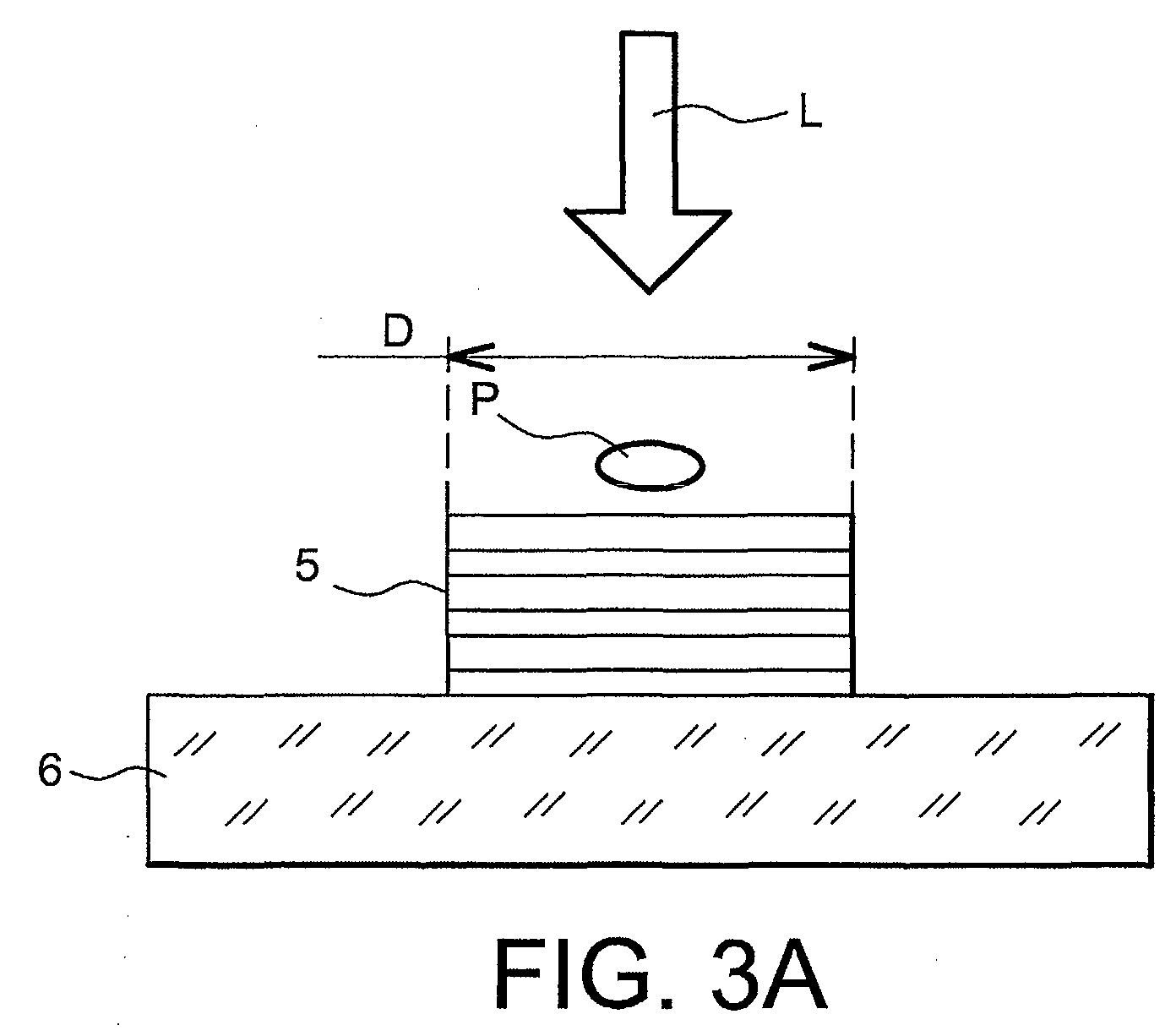
- Figures 3A and 3B show, respectively, a cross-sectional view and a longitudinal sectional view of an optical device for the displacement of particles according to the invention.
- the device comprises a substrate 6 and a strip 5 formed by at least one thin layer deposited on the substrate 6.
- the strip 5 has a width D and its thickness e varies along the axis perpendicular to its width. The variation of the thickness may be continuous, as shown in FIG. 3B. It can also be obtained by jumps.
- the substrate 6 may be, for example, a glass or silicon substrate.
- the layers constituting the strip 5 may be composed alternately of a high index material (Si, HfO 2 , TiO 2 , Si 3 N 4 , Al 2 O 3 , Ta 2 O 5 , SiO 2 , MgF 2 , ITO, In 2 O 3 , InP) and a low index material (SiO 2 , MgF 2 , LiF). They can be produced by physical vapor deposition, commonly known as PVD (Physical Vapor Deposition), by chemical vapor deposition commonly known as CVD (CVD for "Chemical Vapor Deposition”), or by sol-gel
- a particle P that needs to be moved is placed on the strip 5.
- the substrate 6 is illuminated on its totality by a light L whose wavelength can vary, for example, from the field of infrared to ultraviolet field. Interference between the incident light L and the light reflected by the device (substrate + tape) then lead to the formation of a standing wave on the surface of device.
- the band 5 is made in one (of) material (x) of refractive index (s) given (s).
- the thickness variation of the strip 5 along its axis longitudinal produces an optical thickness gradient according to this axis.
- This optical thickness gradient creates a intensity gradient of the standing wave in which is the particle P.
- the particle P is then moved under the effect of pressure variation of radiation applied to it.
- the particle P is moves longitudinally along the axis of strip 5, from the lowest thicknesses to the thicknesses the higher (direction of movement S in Figure 3B).
- the direction of movement of the particle (to the left or to the right) is conditioned by the structure of stacking (indices and thicknesses of the layers).
- the optical thickness gradient is obtained by varying the thickness of the strip 5.
- the invention also relates to other modes of production. So, for example, does the invention concern also a structure in which the thickness of band 5 is constant. That's the variation index of the material (s) itself (themselves) which realizes the optical thickness gradient. It is also possible to advantageously combine the two solutions (index variation and thickness variation) to obtain variations in optical thickness desired.
- Figure 4 shows an improvement of optical device for moving particles according to the invention.
- a structure 7 composed of at least one layer thin is placed above the 5 band so that the band 5 and the structure 7 constitute a cavity of Fabry-Perot.
- the composition of the layers of the structure 7 can be, for example, identical to those of layers of the band 5. Choosing as distance average between band 5 and structure 7 a distance equal to an integer multiple of half the length used, it is possible to increase, by resonance, the intensity of the wave inside the cavity. The reflectivities of band 5 and the structure 7 are then chosen so that a peak of the resonance is positioned at the level of the particle P.
- Figures 5A and 5B represent, respectively, the intensity of the field electric E and the velocity V of the particle in function of the angle of incidence ⁇ of the illuminating wave the device. It appears that the intensity of the field electrical and velocity of the particle vary from the same way. For a wave of zero incidence, the intensity of the field and the speed of the particle are maximum and, when the incidence increases, the intensity of the field and velocity of the particle decrease.
- FIGS 6 and 7 illustrate these different devices as non-limiting examples.
- FIG. 6 represents a view from above of a example of an optical switching device particles according to the invention.
- Four strips of layers 8, 9, 10, 11 are deposited on a substrate 1.
- band 8 is divided into the three bands 9, 10 and 11.
- the strips 8, 9, 10 and 11 are respectively centered by example, on the wavelengths ⁇ 1, ⁇ 2, ⁇ 1, ⁇ 3, where ⁇ 1, ⁇ 2 and ⁇ 3 are three different wavelengths such that ⁇ 3> ⁇ 2> ⁇ 1.
- the bands are centered on the different wavelengths in a manner known in by choosing the reflectivity of materials and optimizing the thickness and the number of layers.
- the direction of movement of particles on the bands 8, 9, 10, 11 goes from the left from the figure to the right of the figure.
- the routing can be done by changing the incidence of the wave compared to normal.
- the effect of incidence of the wave makes it possible to shift the function spectral wavelength ⁇ 3 to length wave ⁇ 1.
- An embodiment advantageous may be to use the polarization of the wave that illuminates the device. We then choose a polarization parallel to the plane of incidence that allows better spectral separation of the channels 9, 10 and 11.
- Figure 7 shows an example of a device particle analysis according to the invention.
- the device includes a dispenser 12, an analysis block 13 and a reading device 14.
- the analysis block 13 comprises a substrate 1, a first device switching from an input channel 15 to three channels 16, 17, 18, three analysis circuits 19, 20, 21, one second device for switching the three lanes 16, 17, 18 to an output path 22 and a laser 23.
- the analysis circuits 19, 20, 21 are circuits of reading, for example fluorescence enhancement. Each switching device works as indicated above.
- Dispenser 12 supplies the particles to analyze. A first series of measures can then be deduced from the analyzes carried out by the circuits 19, 20, 21.
- the laser 23 which illuminates the exit path 22 allows, if necessary, to break the particles.
- the pieces of particles thus obtained are transferred to the reading device 14 which then performs a series of measurements on the pieces of particles.
Landscapes
- Physics & Mathematics (AREA)
- Spectroscopy & Molecular Physics (AREA)
- Engineering & Computer Science (AREA)
- General Engineering & Computer Science (AREA)
- High Energy & Nuclear Physics (AREA)
- Investigating Or Analysing Materials By Optical Means (AREA)
- Physical Or Chemical Processes And Apparatus (AREA)
- Investigating, Analyzing Materials By Fluorescence Or Luminescence (AREA)
- Lasers (AREA)
Abstract
Description
- la figure 1 représente un moyen de déplacement de particule de type « pince optique » selon l'art antérieur ;
- la figure 2 représente un moyen de déplacement de particule par onde évanescente selon l'art antérieur ;
- les figure 3A et 3B représentent un dispositif optique pour le déplacement de particules selon l'invention ;
- la figure 4 représente un perfectionnement du dispositif optique de déplacement de particules selon l'invention ;
- les figures 5A-5B représentent des courbes illustrant la corrélation entre la variation du champ électrique en surface du dispositif optique selon l'invention et la vitesse de déplacement des particules ;
- la figure 6 représente un exemple de dispositif d'aiguillage optique de particules selon l'invention ;
- la figure 7 représente un exemple de dispositif d'analyse de particules selon l'invention.
- un dispositif d'aiguillage optique comprenant au moins un dispositif optique pour le déplacement de particules selon l'invention ;
- un dispositif de tri de particules comprenant au moins un dispositif d'aiguillage optique selon l'invention ; et
- un dispositif d'analyse de particules comprenant au moins un dispositif de tri de particules selon l'invention.
Claims (22)
- Dispositif optique pour le déplacement de particules (P), caractérisé en ce qu'il comprend un substrat (6) sur lequel est déposée au moins une bande (5) d'au moins une couche mince, la bande (5) présentant un gradient d'épaisseur optique selon un axe de sorte que le déplacement d'une particule (P) s'effectue selon cet axe lorsqu'une onde électromagnétique (L) éclaire le dispositif.
- Dispositif selon la revendication 1, caractérisé en ce que la bande (5) a une épaisseur (e) qui varie selon la direction de l'axe.
- Dispositif selon la revendication 1 ou 2, caractérisé en ce que la bande (5) est composée de matériaux dont l'indice varie selon la direction de l'axe.
- Dispositif selon l'une quelconque des revendications 1 à 3, caractérisé en ce qu'il comprend une structure (7) constituée d'au moins une couche mince, placée en face de la bande (5) de sorte que la bande (5) et la structure (7) constituent une cavité de Fabry-Pérot.
- Dispositif selon la revendication 4, caractérisé en ce que la distance entre la bande (5) et la structure (7) est égale à un multiple entier de la moitié de la longueur d'onde qui éclaire le dispositif de façon à accroítre par résonance l'intensité de l'onde à l'intérieur de la cavité.
- Dispositif selon la revendication 5, caractérisé en ce que la bande (5) et la structure (7) ont des réflectivités choisies pour qu'un pic de résonance soit positionné au niveau d'une particule.
- Dispositif selon l'une quelconque des revendications précédentes, caractérisé en ce que la bande (5) est constituée d'une alternance de couches de haut indice et de bas indice.
- Dispositif selon l'une quelconque des revendications 4 à 7, caractérisé en ce que la structure (7) est constituée d'une alternance de couches de haut indice et de bas indice.
- Dispositif selon l'une quelconque des revendications 7 ou 8, caractérisé en ce que les couches de haut indice sont réalisées dans un matériau choisi parmi Si, HfO2, TiO2, Si3N4, Al2O3, Ta2O5, ITO, In2O3, SiO2, MgF2 ou InP.
- Dispositif selon l'une quelconque des revendications 7 à 9, caractérisé en ce que les couches de bas indice sont réalisées dans un matériau choisi parmi SiO2, MgF2, ou LiF.
- Dispositif d'aiguillage de particules d'une première voie vers une deuxième voie, caractérisé en ce qu'il comprend au moins deux dispositifs optiques pour le déplacement de particules selon l'une quelconque des revendications 1 à 10, chaque dispositif optique constituant une voie.
- Dispositif d'aiguillage de particules selon la revendication 11, caractérisé en ce que chaque dispositif optique constituant une voie comprend une bande (8, 9, 10, 11)) d'au moins une couche mince, chaque bande étant centrée à une longueur d'onde donnée (λ1, λ2, λ3) et présentant un gradient d'épaisseur optique selon un axe de sorte que le déplacement d'une particule s'effectue selon cet axe lorsqu'une onde optique ayant comme longueur d'onde la longueur d'onde sur laquelle la bande est centrée éclaire le dispositif.
- Dispositif de tri de particules, caractérisé en ce qu'il comprend au moins un dispositif d'aiguillage selon l'une des revendications 11 ou 12.
- Dispositif d'analyse de particules, caractérisé en ce qu'il comprend au moins un dispositif de tri de particules selon la revendication 13.
- Dispositif d'analyse de particules selon la revendication 14, caractérisé en ce qu'il comprend un dispositif d'aiguillage de particules réalisant une jonction entre une voie d'entrée (15) et n voies intermédiaires (16, 17, 18) et un dispositif d'aiguillage réalisant une jonction entre lesdites n voies intermédiaires (16, 17, 18) et une voie de sortie (22), un dispositif d'analyse (19, 20, 21) étant placé sur au moins une voie intermédiaire parmi les n voies (16, 17, 18).
- Dispositif selon la revendication 15, caractérisé en ce que le dispositif d'analyse est un dispositif d'analyse par fluorescence.
- Dispositif d'analyse selon la revendication 15 ou 16, caractérisé en ce qu'il comprend un laser (23) pour illuminer la voie de sortie (22) et casser les particules qui s'y déplacent et un dispositif de lecture (14) pour analyser les morceaux de particules cassées.
- Procédé optique de déplacement de particules selon un axe, caractérisé en ce qu'il comprend la formation d'un gradient d'intensité d'onde stationnaire au niveau d'une particule à déplacer, par illumination, à l'aide d'une onde électromagnétique, d'un substrat (1) sur lequel est déposée au moins une bande (5) d'au moins une couche mince présentant un gradient d'épaisseur optique selon l'axe.
- Procédé selon la revendication 18, caractérisé en ce que la vitesse de déplacement de la particule est modifiée en faisant varier l'incidence de l'onde électromagnétique sur le substrat.
- Procédé d'aiguillage de particules d'une première voie vers une deuxième voie, caractérisé en ce que le déplacement d'une particule sur une voie est effectué selon le procédé de la revendication 18 et en ce que l'aiguillage d'une particule est réalisé par modification de la longueur d'onde de l'onde qui illumine le substrat (1) d'une première valeur (λ1) vers une deuxième valeur (λ2), la première valeur étant une valeur sur laquelle est centrée la première voie qui est constituée d'une première bande (8) d'au moins une couche mince déposée sur le substrat (1) et la deuxième valeur étant une valeur sur laquelle est centrée la deuxième voie qui est constituée d'une deuxième bande (9) d'au moins une couche mince déposée sur le substrat.
- Procédé de tri de particules, caractérisé en ce qu'il met en euvre un procédé d'aiguillage selon la revendication 20.
- Procédé d'analyse de particules, caractérisé en ce qu'il met en oeuvre un procédé de tri selon la revendication 21.
Applications Claiming Priority (2)
| Application Number | Priority Date | Filing Date | Title |
|---|---|---|---|
| FR0116117 | 2001-12-13 | ||
| FR0116117A FR2833716B1 (fr) | 2001-12-13 | 2001-12-13 | Dispositif optique et procede optique pour le deplacement de particules |
Publications (1)
| Publication Number | Publication Date |
|---|---|
| EP1324645A1 true EP1324645A1 (fr) | 2003-07-02 |
Family
ID=8870437
Family Applications (1)
| Application Number | Title | Priority Date | Filing Date |
|---|---|---|---|
| EP02293061A Withdrawn EP1324645A1 (fr) | 2001-12-13 | 2002-12-11 | Dispositif optique et procédé optique pour le déplacement de particules |
Country Status (4)
| Country | Link |
|---|---|
| US (1) | US20030111594A1 (fr) |
| EP (1) | EP1324645A1 (fr) |
| JP (1) | JP2003262589A (fr) |
| FR (1) | FR2833716B1 (fr) |
Cited By (3)
| Publication number | Priority date | Publication date | Assignee | Title |
|---|---|---|---|---|
| FR2863182A1 (fr) * | 2003-12-04 | 2005-06-10 | Commissariat Energie Atomique | Procede de concentration de particules. |
| FR2863360A1 (fr) * | 2003-12-04 | 2005-06-10 | Commissariat Energie Atomique | Dispositif de separation d'objets par voie optique. |
| FR2863181A1 (fr) * | 2003-12-04 | 2005-06-10 | Commissariat Energie Atomique | Procede de tri de particules. |
Families Citing this family (8)
| Publication number | Priority date | Publication date | Assignee | Title |
|---|---|---|---|---|
| US9815058B2 (en) * | 2003-05-08 | 2017-11-14 | The University Court Of The University Of St Andrews | Fractionation of particles |
| FR2860886B1 (fr) * | 2003-10-14 | 2005-12-23 | Commissariat Energie Atomique | Dispositif de deplacement de particules |
| GB0618605D0 (en) * | 2006-09-21 | 2006-11-01 | Univ St Andrews | Optical sorting |
| GB0618606D0 (en) * | 2006-09-21 | 2006-11-01 | Univ St Andrews | Optical sorting |
| EP1905755A1 (fr) * | 2006-09-26 | 2008-04-02 | Lonza Ag | Procédé de synthèse du 2,2 ,6-tribromobiphényl |
| US9841367B2 (en) | 2011-09-16 | 2017-12-12 | The University Of North Carolina At Charlotte | Methods and devices for optical sorting of microspheres based on their resonant optical properties |
| US9242248B2 (en) * | 2011-09-16 | 2016-01-26 | The University Of North Carolina At Charlotte | Methods and devices for optical sorting of microspheres based on their resonant optical properties |
| US10919268B1 (en) * | 2019-09-26 | 2021-02-16 | United States Of America As Represented By The Administrator Of Nasa | Coatings for multilayer insulation materials |
Citations (7)
| Publication number | Priority date | Publication date | Assignee | Title |
|---|---|---|---|---|
| JPH0196604A (ja) * | 1987-10-09 | 1989-04-14 | Hitachi Ltd | 光導波路およびその製造方法 |
| US4887721A (en) * | 1987-11-30 | 1989-12-19 | The United States Of America As Represented By The United States Department Of Energy | Laser particle sorter |
| US5079169A (en) * | 1990-05-22 | 1992-01-07 | The Regents Of The Stanford Leland Junior University | Method for optically manipulating polymer filaments |
| US5100627A (en) * | 1989-11-30 | 1992-03-31 | The Regents Of The University Of California | Chamber for the optical manipulation of microscopic particles |
| US5227648A (en) * | 1991-12-03 | 1993-07-13 | Woo Jong Chun | Resonance cavity photodiode array resolving wavelength and spectrum |
| EP0569181A1 (fr) * | 1992-05-08 | 1993-11-10 | AT&T Corp. | Dispositif optique intégré pour coupler des fibres optiques à des éléments avec des rayons de lumière asymétriques |
| US5793485A (en) * | 1995-03-20 | 1998-08-11 | Sandia Corporation | Resonant-cavity apparatus for cytometry or particle analysis |
Family Cites Families (10)
| Publication number | Priority date | Publication date | Assignee | Title |
|---|---|---|---|---|
| US6744038B2 (en) * | 2000-11-13 | 2004-06-01 | Genoptix, Inc. | Methods of separating particles using an optical gradient |
| US6784420B2 (en) * | 2000-11-13 | 2004-08-31 | Genoptix, Inc. | Method of separating particles using an optical gradient |
| US20020115163A1 (en) * | 2000-11-13 | 2002-08-22 | Genoptix | Methods for sorting particles by size and elasticity |
| US20030007894A1 (en) * | 2001-04-27 | 2003-01-09 | Genoptix | Methods and apparatus for use of optical forces for identification, characterization and/or sorting of particles |
| US20020113204A1 (en) * | 2000-11-13 | 2002-08-22 | Genoptix | Apparatus for collection of sorted particles |
| US20020123112A1 (en) * | 2000-11-13 | 2002-09-05 | Genoptix | Methods for increasing detection sensitivity in optical dielectric sorting systems |
| US20020108859A1 (en) * | 2000-11-13 | 2002-08-15 | Genoptix | Methods for modifying interaction between dielectric particles and surfaces |
| US6833542B2 (en) * | 2000-11-13 | 2004-12-21 | Genoptix, Inc. | Method for sorting particles |
| US20020160470A1 (en) * | 2000-11-13 | 2002-10-31 | Genoptix | Methods and apparatus for generating and utilizing linear moving optical gradients |
| US20030124516A1 (en) * | 2001-04-27 | 2003-07-03 | Genoptix, Inc. | Method of using optical interrogation to determine a biological property of a cell or population of cells |
-
2001
- 2001-12-13 FR FR0116117A patent/FR2833716B1/fr not_active Expired - Fee Related
-
2002
- 2002-12-06 US US10/310,767 patent/US20030111594A1/en not_active Abandoned
- 2002-12-11 EP EP02293061A patent/EP1324645A1/fr not_active Withdrawn
- 2002-12-12 JP JP2002361289A patent/JP2003262589A/ja not_active Withdrawn
Patent Citations (7)
| Publication number | Priority date | Publication date | Assignee | Title |
|---|---|---|---|---|
| JPH0196604A (ja) * | 1987-10-09 | 1989-04-14 | Hitachi Ltd | 光導波路およびその製造方法 |
| US4887721A (en) * | 1987-11-30 | 1989-12-19 | The United States Of America As Represented By The United States Department Of Energy | Laser particle sorter |
| US5100627A (en) * | 1989-11-30 | 1992-03-31 | The Regents Of The University Of California | Chamber for the optical manipulation of microscopic particles |
| US5079169A (en) * | 1990-05-22 | 1992-01-07 | The Regents Of The Stanford Leland Junior University | Method for optically manipulating polymer filaments |
| US5227648A (en) * | 1991-12-03 | 1993-07-13 | Woo Jong Chun | Resonance cavity photodiode array resolving wavelength and spectrum |
| EP0569181A1 (fr) * | 1992-05-08 | 1993-11-10 | AT&T Corp. | Dispositif optique intégré pour coupler des fibres optiques à des éléments avec des rayons de lumière asymétriques |
| US5793485A (en) * | 1995-03-20 | 1998-08-11 | Sandia Corporation | Resonant-cavity apparatus for cytometry or particle analysis |
Non-Patent Citations (3)
| Title |
|---|
| PATENT ABSTRACTS OF JAPAN vol. 013, no. 332 (P - 905) 26 July 1989 (1989-07-26) * |
| SATOSHI KAWATA ET AL: "MOVEMENT OF MICROMETER-SIZED PARTICLES IN THE EVANESCENT FIELD OF A LASER BEAM", OPTICS LETTERS, OPTICAL SOCIETY OF AMERICA, WASHINGTON, US, vol. 17, no. 11, 1 June 1992 (1992-06-01), pages 772 - 774, XP000274845, ISSN: 0146-9592 * |
| TANAKA T ET AL: "OPTICALLY INDUCED PROPULSION OF SMALL PARTICLES IN AN EVENESCENT FIELD OF HIGHER PROPAGATION MODE IN A MULTIMODE, CHANNELED WAVEGUIDE", APPLIED PHYSICS LETTERS, AMERICAN INSTITUTE OF PHYSICS. NEW YORK, US, vol. 77, no. 20, 13 November 2000 (2000-11-13), pages 3131 - 3133, XP000970277, ISSN: 0003-6951 * |
Cited By (9)
| Publication number | Priority date | Publication date | Assignee | Title |
|---|---|---|---|---|
| FR2863182A1 (fr) * | 2003-12-04 | 2005-06-10 | Commissariat Energie Atomique | Procede de concentration de particules. |
| FR2863360A1 (fr) * | 2003-12-04 | 2005-06-10 | Commissariat Energie Atomique | Dispositif de separation d'objets par voie optique. |
| FR2863181A1 (fr) * | 2003-12-04 | 2005-06-10 | Commissariat Energie Atomique | Procede de tri de particules. |
| WO2005054819A1 (fr) * | 2003-12-04 | 2005-06-16 | Commissariat A L'energie Atomique | Procede de concentration de particules |
| WO2005054832A1 (fr) * | 2003-12-04 | 2005-06-16 | Commissariat A L'energie Atomique | Procede de tri de particules |
| WO2005054818A1 (fr) * | 2003-12-04 | 2005-06-16 | Commissariat A L'energie Atomique | Dispositif de separation d'objets faisant appel a un procede optique |
| US7366377B2 (en) | 2003-12-04 | 2008-04-29 | Commissariat A L'energie Atomique | Particle concentration method |
| US7402795B2 (en) | 2003-12-04 | 2008-07-22 | Commissariat A L'energie Atomique | Particle sorting method |
| US7511263B2 (en) | 2003-12-04 | 2009-03-31 | Commissariat A L'energie Atomique | Object separation device using optical method |
Also Published As
| Publication number | Publication date |
|---|---|
| FR2833716B1 (fr) | 2004-01-30 |
| JP2003262589A (ja) | 2003-09-19 |
| US20030111594A1 (en) | 2003-06-19 |
| FR2833716A1 (fr) | 2003-06-20 |
Similar Documents
| Publication | Publication Date | Title |
|---|---|---|
| EP2616855B1 (fr) | Filtre spectral passe bande à forte sélectivité et polarisation contrôlée | |
| EP0033048B1 (fr) | Interféromètre à cavité optique accordable comprenant une fibre optique monomode et application au filtrage et à la spectrographie | |
| FR2555324A1 (fr) | Perfectionnements aux dispositifs optiques, notamment de demultiplexage et de multiplexage, et aux filtres optiques utilises dans de tels dispositifs | |
| EP3339924A1 (fr) | Circuit photonique integre optimise | |
| FR2570839A1 (fr) | Dispositif de couplage entre des guides d'onde, monolithiquement integre avec ceux-ci sur un substrat semiconducteur | |
| FR2833716A1 (fr) | Dispositif optique et procede optique pour le deplacement de particules | |
| EP3855068B1 (fr) | Dispositif de projection distribuée de lumière | |
| EP3425344A1 (fr) | Capteur de deplacement avec micro-résonateur en anneau segmenté | |
| EP0742453A1 (fr) | Miroir à large bande et à haute réflectivité et procédé de réalisation d'un tel miroir | |
| EP1000328B1 (fr) | Micromonochromateur et procede de realisation de celui-ci | |
| FR2837935A1 (fr) | Element optique a cristal photonique unidimensionnel, et dispositifs optiques le comportant | |
| FR2837002A1 (fr) | Element optique utilisant un cristal photonique bidimensionnel et demultiplexeur associe | |
| EP1058138A1 (fr) | Multiplexeur/démultiplexeur optique à trois guides d'onde | |
| CA2769478A1 (fr) | Dispositifs electro-optiques bases sur la variation d'indice ou d'absorption dans des transitions isb | |
| US7440654B2 (en) | Wavelength multiplexer/demultiplexer comprising an optically dispersive stratified body | |
| EP1102046A1 (fr) | Etalon pour des longeurs d'ondes multiples | |
| FR3052923A1 (fr) | Reflecteur optique resonant a multiples couches minces de materiaux dielectriques, capteur optique et dispositif d'amplification laser comportant un tel reflecteur | |
| CA2102593A1 (fr) | Dispositif de mesure d'une caracteristique d'un objet en optique integree, par interferometrie | |
| EP4034923B1 (fr) | Système optique et procédé de réalisation | |
| EP1546770B1 (fr) | Composant de filtrage optique en creneau | |
| EP0876594B1 (fr) | Filtre fabry-perot accordable pour determiner une concentration de gaz | |
| FR2732478A1 (fr) | Structure a deux guides optiques insensible a la polarisation et procede de realisation | |
| EP4528337A2 (fr) | Filtre multispectral pour une radiation électromagnétique et procédé de fabrication dudit filtre | |
| FR3052913A1 (fr) | Capteur optique comportant un reflecteur optique resonant a multiples couches minces de materiaux dielectriques | |
| JP2002182026A (ja) | 光学素子およびそれを用いた分光装置 |
Legal Events
| Date | Code | Title | Description |
|---|---|---|---|
| PUAI | Public reference made under article 153(3) epc to a published international application that has entered the european phase |
Free format text: ORIGINAL CODE: 0009012 |
|
| AK | Designated contracting states |
Designated state(s): AT BE BG CH CY CZ DE DK EE ES FI FR GB GR IE IT LI LU MC NL PT SE SI SK TR |
|
| AX | Request for extension of the european patent |
Extension state: AL LT LV MK RO |
|
| 17P | Request for examination filed |
Effective date: 20031217 |
|
| AKX | Designation fees paid |
Designated state(s): DE GB IT |
|
| 17Q | First examination report despatched |
Effective date: 20040301 |
|
| GRAP | Despatch of communication of intention to grant a patent |
Free format text: ORIGINAL CODE: EPIDOSNIGR1 |
|
| RTI1 | Title (correction) |
Free format text: OPTICAL METHOD FOR DISPLACING PARTICLES |
|
| STAA | Information on the status of an ep patent application or granted ep patent |
Free format text: STATUS: THE APPLICATION IS DEEMED TO BE WITHDRAWN |
|
| 18D | Application deemed to be withdrawn |
Effective date: 20050826 |