EP1324602A2 - Method and apparatus for image and video display - Google Patents
Method and apparatus for image and video display Download PDFInfo
- Publication number
- EP1324602A2 EP1324602A2 EP02258025A EP02258025A EP1324602A2 EP 1324602 A2 EP1324602 A2 EP 1324602A2 EP 02258025 A EP02258025 A EP 02258025A EP 02258025 A EP02258025 A EP 02258025A EP 1324602 A2 EP1324602 A2 EP 1324602A2
- Authority
- EP
- European Patent Office
- Prior art keywords
- display
- light
- image information
- elements
- receivers
- Prior art date
- Legal status (The legal status is an assumption and is not a legal conclusion. Google has not performed a legal analysis and makes no representation as to the accuracy of the status listed.)
- Granted
Links
Images


Classifications
-
- G—PHYSICS
- G09—EDUCATION; CRYPTOGRAPHY; DISPLAY; ADVERTISING; SEALS
- G09G—ARRANGEMENTS OR CIRCUITS FOR CONTROL OF INDICATING DEVICES USING STATIC MEANS TO PRESENT VARIABLE INFORMATION
- G09G3/00—Control arrangements or circuits, of interest only in connection with visual indicators other than cathode-ray tubes
- G09G3/001—Control arrangements or circuits, of interest only in connection with visual indicators other than cathode-ray tubes using specific devices not provided for in groups G09G3/02 - G09G3/36, e.g. using an intermediate record carrier such as a film slide; Projection systems; Display of non-alphanumerical information, solely or in combination with alphanumerical information, e.g. digital display on projected diapositive as background
- G09G3/002—Control arrangements or circuits, of interest only in connection with visual indicators other than cathode-ray tubes using specific devices not provided for in groups G09G3/02 - G09G3/36, e.g. using an intermediate record carrier such as a film slide; Projection systems; Display of non-alphanumerical information, solely or in combination with alphanumerical information, e.g. digital display on projected diapositive as background to project the image of a two-dimensional display, such as an array of light emitting or modulating elements or a CRT
-
- G—PHYSICS
- G09—EDUCATION; CRYPTOGRAPHY; DISPLAY; ADVERTISING; SEALS
- G09G—ARRANGEMENTS OR CIRCUITS FOR CONTROL OF INDICATING DEVICES USING STATIC MEANS TO PRESENT VARIABLE INFORMATION
- G09G3/00—Control arrangements or circuits, of interest only in connection with visual indicators other than cathode-ray tubes
- G09G3/02—Control arrangements or circuits, of interest only in connection with visual indicators other than cathode-ray tubes by tracing or scanning a light beam on a screen
-
- H—ELECTRICITY
- H04—ELECTRIC COMMUNICATION TECHNIQUE
- H04N—PICTORIAL COMMUNICATION, e.g. TELEVISION
- H04N9/00—Details of colour television systems
- H04N9/12—Picture reproducers
- H04N9/30—Picture reproducers using solid-state colour display devices
-
- G—PHYSICS
- G09—EDUCATION; CRYPTOGRAPHY; DISPLAY; ADVERTISING; SEALS
- G09G—ARRANGEMENTS OR CIRCUITS FOR CONTROL OF INDICATING DEVICES USING STATIC MEANS TO PRESENT VARIABLE INFORMATION
- G09G2360/00—Aspects of the architecture of display systems
- G09G2360/14—Detecting light within display terminals, e.g. using a single or a plurality of photosensors
- G09G2360/141—Detecting light within display terminals, e.g. using a single or a plurality of photosensors the light conveying information used for selecting or modulating the light emitting or modulating element
-
- H—ELECTRICITY
- H04—ELECTRIC COMMUNICATION TECHNIQUE
- H04N—PICTORIAL COMMUNICATION, e.g. TELEVISION
- H04N9/00—Details of colour television systems
- H04N9/12—Picture reproducers
- H04N9/31—Projection devices for colour picture display, e.g. using electronic spatial light modulators [ESLM]
- H04N9/3141—Constructional details thereof
- H04N9/3147—Multi-projection systems
Definitions
- the present invention relates generally to displaying images and/or video (collectively "images") and, more particularly, to displaying images with optically-addressed, or broadcast-addressed displays.
- optical projection systems which may employ either front or rear projection passive display screens.
- Other techniques may include active, liquid crystal display (LCD) projection devices or electrically-addressed, emissive displays (e.g., plasma flat panel displays).
- LCD liquid crystal display
- emissive displays e.g., plasma flat panel displays
- projection systems generally employ passive screens, either reflective for front projection or diffusive for rear projection, all of the optical energy to display images with such systems is typically generated by the projector.
- projection equipment capable of providing sufficient optical energy may be relatively expensive and may consume a significant amount of power in operation.
- Image quality for projection display systems may also suffer as a result of flicker and/or sequential color artifacts due to the use of a color wheel in combination with a "digital micromirror device" (which is a trademark of Texas Instruments, Inc.), for example.
- the effects on image quality resulting from sequential color artifacts may include rainbow-colored shadows that follow rapidly moving objects in video images.
- Active LCD projection devices may also have certain disadvantages such as inefficient use of optical power as a result of polarizing visible-light before passing it through the LCD panels.
- Such polarizing is typically accomplished by employing known techniques, such as the use of a polarizing filter.
- Electrically addressed emissive displays have the further drawback of design complexity and, design and product cost associated with electrically addressing each pixel of such displays when displaying images. Thus, based on the foregoing, additional techniques for displaying images may be desirable.
- the present invention relates to a display configured to display images that includes multiple display elements capable of controlling light within a visible-light spectrum.
- the display elements are arranged over a display surface of the display.
- the display also includes one or more receivers arranged with the display elements over the display surface.
- the receivers are coupled with the display elements and receive transmitted image information. The receivers activate the display elements in response to, and in correspondence with, the image information.
- the present invention is directed to method and apparatus for displaying images.
- images may include still images or video images and, for consistency, will be referred to herein as images.
- Figs. 1 and 2 illustrate prior art systems employing passive screens that may be used to display such images.
- System 10 may include a projector 12 and a passive screen 14.
- a viewer 16 is typically located on the same side of passive screen 14 as projector 12 when viewing images, such as image 18.
- optical energy including image 18 may be projected by projector 12 onto screen 14. Image 18 may then be reflected from screen 14 for viewing by viewer 16.
- the optical energy to project image 18 onto screen 14 is provided by projector 12, and thus projector 12 may include a light source capable of generating thousands of lumens of optical energy, depending on the particular application.
- Such light sources are generally expensive, and may generate significant amounts of heat, for which cooling fans, and other design elements, would typically be employed to dissipate, adding further cost to projector 12. Cooling fans also may generate audible noise, which is undesirable. Employing such a light source may also be required to compensate for the effects of ambient light on the brightness and quality of image 18.
- Fig. 2 illustrates a prior art rear projection display system shown generally at 20.
- System 20 in similar fashion to system IO, may include projector 22 and passive screen 24.
- viewer 26 would typically be on the opposite side of passive screen 24 from projector 22, and image 28 would typically be projected onto the back of passive screen 24 via a mirror 30.
- image 28 would typically be composed of optical energy that is diffused by passive screen 24.
- system 20 is self-contained, it may not be affected by surrounding light to the same extent as system 10. Nonetheless, projector 22 provides the optical energy employed to project image 28 and, therefore, typically employs a light source that is comparable with the light sources previously discussed with respect to Fig. 1.
- the quality and brightness of image 28, when displayed using system 20 may be affected by the use of mirror 30. Use of mirror 30 may result in loss of optical energy and/or distortion of image 28.
- Fig. 3 illustrates a prior art active liquid crystal display (LCD) matrix, indicated generally at 40.
- LCD liquid crystal display
- matrix 40 may include a plurality of pixels 42.
- Each pixel 42 may further include control circuitry 44 and a light valve 46. Pixels 42 may be addressed, or accessed, via address lines 48.
- Matrix 40 may form a part of a transmissive display. Transmissive, in this context, means that light generated on one side of matrix 40 may be transmitted via pixels 42 to display an image.
- Systems employing matrix 40, as with systems 10 and 20, have certain drawbacks. Because matrix 40 is transmissive, optical energy must be supplied via an independent, typically discrete, light source, as has been previously discussed. Such systems are known, and typically employ complex optics that may include dichroic mirrors, polarizers, spinning filter wheels, and/or multiple lenses. In some embodiments, optical/electronic devices, such as digital micromirror devices may be employed. Employing such optics and/or optical/electronics typically reduces the amount of light that is visible by a viewer of an image on such a display system because each optical stage results in some measurable optical energy loss. Such optical energy loss, often exceeding 80%, may adversely impact image brightness and/or image quality, such as image sharpness or color hue. Based on these drawbacks, and on the previously discussed disadvantages of systems 10 and 20, alternative techniques for displaying images may be desirable.
- Display system 50 includes a beam projector 52 and an optically-addressed screen 54.
- Screen 54 may take various forms, such as the embodiments discussed in further detail hereafter. Briefly, however, screen 54 is shown segmented, indicating an arrangement of display elements, as will be discussed below, which may cooperate with one another when displaying an image 58.
- the display elements of screen 54 may be emissive or transmissive, and the invention is not limited in scope to any particular display element.
- viewer 56 would typically view images displayed using system 50 on an opposite side (front side) of emissive screen 54 from projector 52, which would typically be located behind, or on the backside of screen 54.
- screen 54 may include various types of receivers for receiving image information to be displayed. In the embodiment illustrated in Fig. 4, such receivers may be oriented so as to receive such image information on the backside of screen 54. In this respect, image 58 may be projected onto screen 54 via mirror 60. As will also be discussed further below, in certain embodiments, screen 54 may itself supply optical energy to display image 58 (emitting light within the visible-light spectrum). In such a situation, projector 52 would not be limited to projecting image 58 by employing visible-spectrum light and thus the energy emitted by projector 52 may be significantly less than the energy that would be employed if projector 52 supplied all the optical energy delivered to viewer 56. Furthermore, as is illustrated by beam path 62, projector 52 may raster, or repetitively scan, emissive screen 54 when displaying image 58, as opposed to projecting the entire image simultaneously.
- Display system 70 includes projector 72 and screen 74, which may be substantially similar to screen 54, depicted in Fig. 4.
- a viewer 76 would typically be located on the same side of screen 74 as projector 72 when viewing images, such as image 78, displayed with display system 70.
- screen 74 may include various types of receivers for receiving image information to be displayed.
- such receivers may be oriented so as to receive such image information on the front side (i.e. viewer side) of screen 74.
- certain embodiments of screen 74 may supply optical energy to display image 78 (emitting light within the visible-light spectrum).
- display image 78 emitting light within the visible-light spectrum.
- projector 72 is not limited to projecting image 78 by employing visible-spectrum light. Other techniques may be employed, and are discussed below.
- screen 54 and screen 74 may include an arrangement of display elements.
- Such display elements may be emissive, transmissive or reflective and would typically be capable of controlling colored light in the visible-light spectrum for displaying images.
- a schematic arrangement of a display according to the present invention is indicated generally at 80 in Fig. 6.
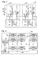
- a sub-arrangement of two adjacent emissive display cells according to an embodiment of the present invention is indicated generally at 100 in Fig. 7.
- each display element may include a single emissive component or may include a plurality of discrete emissive components. These emissive components (and associated circuitry) may be implemented on a flexible circuit substrate, such as any number of polymer film substrates, which are known.
- display 80 may include an arrangement of red emissive components 82, green emissive components 84 and blue emissive components 86, though the invention is not limited in scope in this respect and other combinations are possible, such as those discussed below.
- Such emissive components may be coupled with receivers for receiving image information, as will be discussed with respect to Fig. 7 below.
- red emissive components 82, green emissive components 84, and blue emissive components 86 may be arranged in a predetermined pattern, and may be coupled with a power supply connection 88 and a common ground 90 to provide electric power to the emissive components.
- This predetermined pattern may allow groups of emissive components 92, 94 and 96, for example, to cooperate in emitting colored light within the visible-light spectrum when displaying images.
- Such emissive components thus may supply optical energy, and would typically be arranged very close together over the surface of display 80 (on the order of micrometers in certain embodiments). Therefore, an arrangement such as that depicted in Fig. 6 may allow display of images with improved clarity and brightness as compared with prior art systems.
- Emissive display cell pair 100 may be included in a display, such as those discussed with regard to Figs. 4-6.
- Emissive display cell pair 100 may include individual emissive display cells 102 and 104, both of which are red emissive display cells in the depicted embodiment.
- emissive display cell pair 100 may be coupled with DC power supply 106 and common ground 108 to provide electric power to the various circuit and display elements of emissive display cell display pair 100.
- emissive display cell 102 may include a red emissive component, which, for this embodiment, takes the form of a red light-emitting diode (LED) 110, though alternative emissive components may exist.
- LED 110 may be coupled with transistor 116, resistor 118, impedances 120 through 122, and light-receiving diode (LRD) 112 (also known as a photodiode) via resistor 114.
- LED 110 may be coupled with transistor 116, resistor 118, impedances 120 through 122, and light-receiving diode (LRD) 112 (also known as a photodiode) via resistor 114.
- LPD light-receiving diode
- emissive display cell 104 includes circuit elements 124-136, which correspond to those circuit elements discussed with respect to emissive display cell 102.
- LRDs 112 and 126 may be infrared (IR) LRDs or visible-spectrum LRDs.
- phototransistors such as phototransistor 138 (either IR or visible-spectrum) may be employed to receive image information.
- image information may be projected onto a display, such as those described above, using various frequencies of IR light or using low power visible-spectrum light.
- phototransistor 138 may be adapted to receive IR light at a frequency corresponding with red portions of an image to be displayed.
- LRD 112 the further operation of emissive display cell 102 will be discussed with regard to employing LRD 112.
- the LRD In operation, when IR light of the frequency corresponding to a red portion of an image is received at LRD 112, the LRD would begin to conduct current through resistor 118, which, in turn will apply voltage to the gate of transistor 116, causing it and LED 110 to conduct current. LED 110 will then emit red light.
- the amount of light, or intensity of red light, emitted from LED 110 over a given period of time may be controlled by modulating the duty cycle of IR pulses transmitted to LRD 112 over such a period of time associated with red portions of an image.
- other techniques for modulating the amount of light emitted exist, such as using the amplitude of the IR light projected to control the intensity of the red light emitted by LED 110.
- emissive display cells containing green and/or blue emissive components may be employed, though other combinations of color bands are possible. Such cells would typically have receivers adapted to receive distinct IR light frequencies associated with their respective component colors (color bands), and may be controlled in similar fashion to that described with respect to emissive display cell 102. These green and blue emissive display cells, in cooperation with red emissive display cells, such as 102 and 104, may produce light of a range of colors within the visible-light spectrum.
- Emissive display cells 102 and 104 may also further cooperate to improve the quality of an image displayed using image-sharpening techniques, which are discussed below.
- emissive display cells 102 and 104 are coupled with each other via impedances 120 and 136. Looking again at emissive display cell 102, when transistor 116 is conducting current and LED 110 is emitting light, the gate of transistor 130 of emissive display cell 104 will be pulled electrically toward ground. This will result in it being more difficult to apply sufficient voltage to the gate of transistor 130 to allow LED 124 to conduct current and emit light. The advantage of such a configuration may be improved sharpness and quality of images displayed.
- Emissive display cell 140 includes LRD 142, which may be coupled with red emissive component 144, green emissive component 146, and blue emissive component 148 via decode circuit 150. Numerous decode circuits are known, and the invention is not limited in scope to any particular implementation. It is noted that emissive display cell 140 may include associated circuitry (not shown) for controlling such a display cell, such as depicted in Fig. 7 for emissive display cells 102 and 104.
- image information 152 may be projected onto a display using IR light and received by LRD 142, as has been previously described. Projected image information 152 may be divided into segments corresponding to red (R), green (G) and blue (B), as is depicted in Fig. 8.
- LRD 142 When LRD 142 receives image information 152, it may then electrically communicate that information to decode circuit 150.
- Decode circuit 150 may then decode image information 152 to produce outputs to activate emissive components 144, 146 and 148 at specified intensity levels.
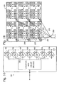
- Display panel 160 may include LRD 162, which may be coupled with a plurality of visible-spectrum cells 164 via connector 166. Such visible-spectrum cells will be discussed in further detail with respect to Fig. 10. Briefly, visible-spectrum cells 164 may include circuitry that indicates each cell's location in panel 160. Image information 168 (defining an image to be displayed by panel 160) may be projected using IR light and received by LRD 162. Image information 168 may include location information (LOC) and color information (C), as is depicted in Fig. 9.
- LOC location information
- C color information
- image information 168 may be communicated to panel 160 in a radio-frequency (RF) signal, which may be received by an RF receiver 170.
- RF radio-frequency
- Image information received by LRD 162 or RF receiver 170 may then be electrically communicated to visible-spectrum cells for displaying an image associated with such information.
- Visible-spectrum cell 180 may include location and color decode circuit 182, which may be coupled with red emissive component 184, green emissive component 186, blue emissive component 188, cyan emissive component 190, magenta emissive component 192, yellow emissive component 194 and white emissive component 196.
- emissive components 184-196 take the form of LEDs, though alternatives may exist.
- Electrically communicated image information may be received by location and color decode circuit 182 from a receiver, such as has been previously described. Such information would typically be transmitted sequentially for all visible-spectrum cells in display panel 160.
- Location and color decode circuit 182 may then convert location information (LOC) and color information (C) to specific address and intensity data for use in directing operation of display elements 184-196.
- LOC location information
- C color information
- image information may or may not directly specify an amount of optical energy to be emitted by emissive components 184-196.
- the image information may be encoded according to the CIELAB color standard, which is known.
- Color decode 182 may then convert the transmitted image information to correspond with the specific display elements employed by such a display system.
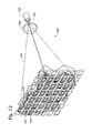
- Display system 200 includes multi-beam projector 202. Because display system 200 includes a plurality of display panels 160, each having a single receiver, projection of image information for such a system may be simplified. In this regard, image information for each panel may be sent to that panel individually. This may be accomplished, for example, by using IR light beams 204, 206, 208, 210, 212 and 214. These beams may transmit image information sequentially to the panels 160, or the beams may transmit image information for each panel 160 in parallel. Alternatively, RF (such as 170) or ultra-violet (UV) (not shown) receivers may be used, and image information for display panels 160 may be transmitted to all display panels 160 sequentially. The specific technique employed will, of course, depend on the particular embodiment.
- IR light beams 204, 206, 208, 210, 212 and 214 These beams may transmit image information sequentially to the panels 160, or the beams may transmit image information for each panel 160 in parallel.
- RF such as 170
- UV ultra
- Display 220 may include an arrangement of transmissive display cells 222.
- Transmissive display cells 222 may each include a receiver/decoder 224, which may be any of the previously described receivers and decoders, though the invention is not so limited.
- Transmissive display cells 222 may also include a display element in the form of a light valve 226, as has been previously described.
- Display 220 may further include a polarizer 228, and a back light 230.
- Optical energy 232 generated by back light 230 may be polarized by polarizer 228, which may then result in polarized light 234 impinging on transmissive display cells 222.
- Image information (not shown), such as has been previously described, may be received by receiver/decoders 224.
- Receiver/decoders 224 may then generate signals to control light valves 226 in correspondence with the received image information to direct at least portions of polarized light 234 to a viewer to display images.
- display cells 222 may take the form of reflective display cells configured to produce an optically-addressed, reflective display.
- Reflective display cells may each include a receiver/decoder 224, and a reflective display element 226.
- display elements 226 may act as reflective light modulators based on image information received by receivers/decoders 224.
- light 230 may be located on the same side of the display screen as a viewer when viewing the images, and that no polarizer need be employed.
- Receivers/decoders 224 thus may generate signals to control reflective display elements 226 in correspondence with the received image information to reflect at least portions of light 232.
Landscapes
- Engineering & Computer Science (AREA)
- Physics & Mathematics (AREA)
- Computer Hardware Design (AREA)
- General Physics & Mathematics (AREA)
- Theoretical Computer Science (AREA)
- Multimedia (AREA)
- Signal Processing (AREA)
- Control Of Indicators Other Than Cathode Ray Tubes (AREA)
- Transforming Electric Information Into Light Information (AREA)
Abstract
Description
Claims (10)
- A display (54, 74) comprising:a plurality of display elements (110, 226) capable of controlling light within a visible-light spectrum, the display elements (110, 226) being arranged over a display surface of the display (54, 74); andone or more receivers (112, 224) arranged with the display elements (110, 226) over the display surface, the one or more receivers (112, 224) being coupled with the display elements (110, 226) and adapted to receive transmitted image information and activate the display elements (110, 226) in response to, and in correspondence with, the image information.
- A display cell (102, 122) comprising:a display element (110, 226) capable of controlling light within a visible-light spectrum;a receiver (112, 224) configured to optically receive image information associated with an image to be displayed; andinterface circuitry (116, 182) coupled with the receiver (112, 224) and the display element (110, 226), the interface circuitry (116, 182) configured to convey signals corresponding to the received image information from the receiver (112, 224) to the display element (110, 226) for display.
- A display system (50, 70) comprising:an optically-addressed display (54, 74) including a plurality of display elements (110, 226) adapted to control light within a visible-light spectrum, and a plurality of receivers (112, 224) coupled with the display elements (110, 226), the receivers (112, 224) being configured to optically receive image information; anda projector (52, 72) configured to project the image information onto the display (54, 74), wherein the projector (52, 72) optically addresses the plurality of display elements (110, 226) via the receivers (112, 224).
- The display (54, 74) of claim 1, the display cell (102, 122) of claim 2, or the display system (50, 70) of claim 3, wherein the display elements (110) include emissive components capable of emitting light within the visible-light spectrum.
- The display (54, 74) of claim 1, the display cell (102, 122) of claim 2, or the display system (50, 70) of claim 3, wherein the display elements (126) include reflective components capable of reflecting light within the visible light spectrum.
- The display (54, 74) of claim 1, the display cell (102, 122) of claim 2, or the display system (50, 70) of claim 3, wherein the display elements (226) include transmissive components configured to regulate transmission of light in correspondence with the image information.
- The display (54, 74) of claim 1, the display cell (102, 122) of claim 2, or the display system (50, 70) of claim 3, wherein the display element(s) (110, 226) include(s) at least one of red, green, blue, cyan, magenta, yellow, white and black display components (82, 84, 86), arranged so as to cooperate in producing light within the visible-light spectrum.
- The display (54, 74) of claim 1, the display cell (102, 122) of claim 2, or the display system (50, 70) of claim 3, wherein the receivers (112, 224) each include at least one of infrared receiving diodes, infrared phototransistors, visible-spectrum light-receiving diodes and radio-frequency receivers.
- The display (54, 74) of claim 1, the display cell (102, 122) of claim 2, or the display system (50, 70) of claim 3, wherein a first display element (110) is associated with a first receiver (112) and a second display element (124) is associated with a second receiver (126), the first display element (110) being coupled with the second receiver (126) and the second display element (124) being coupled with the first receiver (112) so as to affect a relative brightness of the first (110) and second (124) display elements with respect to each other.
- The display system (50, 70) of claim 3, wherein the projector (52, 72) is a beam projector configured to raster the display (54, 74) and optically communicate the image information to the plurality of display elements (110, 226) via the receivers (112, 224) by repetitively sweeping a beam (62) over the display (54, 74).
Applications Claiming Priority (2)
| Application Number | Priority Date | Filing Date | Title |
|---|---|---|---|
| US20112 | 2001-12-14 | ||
| US10/020,112 US6680579B2 (en) | 2001-12-14 | 2001-12-14 | Method and apparatus for image and video display |
Publications (3)
| Publication Number | Publication Date |
|---|---|
| EP1324602A2 true EP1324602A2 (en) | 2003-07-02 |
| EP1324602A3 EP1324602A3 (en) | 2004-05-26 |
| EP1324602B1 EP1324602B1 (en) | 2008-10-08 |
Family
ID=21796816
Family Applications (1)
| Application Number | Title | Priority Date | Filing Date |
|---|---|---|---|
| EP02258025A Expired - Lifetime EP1324602B1 (en) | 2001-12-14 | 2002-11-21 | Method and apparatus for image and video display |
Country Status (4)
| Country | Link |
|---|---|
| US (2) | US6680579B2 (en) |
| EP (1) | EP1324602B1 (en) |
| DE (1) | DE60229206D1 (en) |
| HK (1) | HK1053404B (en) |
Cited By (1)
| Publication number | Priority date | Publication date | Assignee | Title |
|---|---|---|---|---|
| JP2008003613A (en) * | 2007-07-13 | 2008-01-10 | Sony Corp | Video display apparatus and method |
Families Citing this family (37)
| Publication number | Priority date | Publication date | Assignee | Title |
|---|---|---|---|---|
| US20040052076A1 (en) * | 1997-08-26 | 2004-03-18 | Mueller George G. | Controlled lighting methods and apparatus |
| US6965205B2 (en) | 1997-08-26 | 2005-11-15 | Color Kinetics Incorporated | Light emitting diode based products |
| US6777891B2 (en) | 1997-08-26 | 2004-08-17 | Color Kinetics, Incorporated | Methods and apparatus for controlling devices in a networked lighting system |
| US7132804B2 (en) * | 1997-12-17 | 2006-11-07 | Color Kinetics Incorporated | Data delivery track |
| US7303300B2 (en) | 2000-09-27 | 2007-12-04 | Color Kinetics Incorporated | Methods and systems for illuminating household products |
| US6853486B2 (en) * | 2001-03-22 | 2005-02-08 | Hewlett-Packard Development Company, L.P. | Enhanced contrast projection screen |
| US7598684B2 (en) | 2001-05-30 | 2009-10-06 | Philips Solid-State Lighting Solutions, Inc. | Methods and apparatus for controlling devices in a networked lighting system |
| US7358929B2 (en) * | 2001-09-17 | 2008-04-15 | Philips Solid-State Lighting Solutions, Inc. | Tile lighting methods and systems |
| US20030193485A1 (en) * | 2002-04-10 | 2003-10-16 | Da Cunha John M. | Active display system |
| US7057583B2 (en) * | 2002-10-30 | 2006-06-06 | Hewlett-Packard Development Company, L.P. | Display system with display element storage |
| US7426804B2 (en) * | 2002-02-06 | 2008-09-23 | Andersen Corporation | Specialty display window |
| CA2477490A1 (en) * | 2002-02-26 | 2003-09-04 | Martin G. Selbrede | Enhancements to optical flat panel displays |
| US7348970B2 (en) * | 2002-10-02 | 2008-03-25 | Hewlett-Packard Development Company, L.P. | Display system and method of using same |
| WO2004102974A2 (en) * | 2003-05-15 | 2004-11-25 | Koninklijke Philips Electronics N.V. | Display screen comprising a plurality of cells |
| US6811267B1 (en) * | 2003-06-09 | 2004-11-02 | Hewlett-Packard Development Company, L.P. | Display system with nonvisible data projection |
| WO2004114266A1 (en) * | 2003-06-26 | 2004-12-29 | Koninklijke Philips Electronics N.V. | Display screen comprising a plurality of liquid crystal cells and photocells |
| US7133201B2 (en) * | 2003-06-26 | 2006-11-07 | Hewlett-Packard Development Company, L.P. | Compensating display surface |
| US7479938B2 (en) * | 2003-09-19 | 2009-01-20 | Hewlett-Packard Development Company, L.P. | Optically addressable display and method driven by polarized emissions |
| CN1857009A (en) * | 2003-09-25 | 2006-11-01 | 皇家飞利浦电子股份有限公司 | Color display screen comprising a plurality of cells |
| US7733298B2 (en) | 2004-10-19 | 2010-06-08 | Hewlett-Packard Development Company, L.P. | Display device |
| US20060131505A1 (en) * | 2004-12-17 | 2006-06-22 | Eastman Kodak Company | Imaging element |
| US7543956B2 (en) * | 2005-02-28 | 2009-06-09 | Philips Solid-State Lighting Solutions, Inc. | Configurations and methods for embedding electronics or light emitters in manufactured materials |
| US7480096B2 (en) * | 2005-06-08 | 2009-01-20 | Hewlett-Packard Development Company, L.P. | Screen characteristic modification |
| US7494230B2 (en) * | 2005-06-23 | 2009-02-24 | Hewlett-Packard Development Company, Lp | Reflecting non-visible light off one or more mirrors |
| US7443581B2 (en) * | 2005-08-26 | 2008-10-28 | Hewlett-Packard Development Company, L.P. | Adjustable optical characteristic |
| US20070070499A1 (en) * | 2005-09-26 | 2007-03-29 | Fricke Peter J | Optical characteristic |
| US20070081239A1 (en) * | 2005-10-06 | 2007-04-12 | May Gregory J | Optical characteristics of a screen |
| US7609442B2 (en) * | 2005-10-13 | 2009-10-27 | Hewlett-Packard Development Company, L.P. | Synchronizing screen |
| TWI433588B (en) | 2005-12-13 | 2014-04-01 | Koninkl Philips Electronics Nv | Led lighting device |
| DE602007007804D1 (en) * | 2006-11-10 | 2010-08-26 | Philips Solid State Lighting | METHOD AND DEVICE FOR CONTROLLING REAR-OPERATED LED |
| WO2008088383A1 (en) * | 2007-01-05 | 2008-07-24 | Color Kinetics Incorporated | Methods and apparatus for simulating resistive loads |
| US8416302B2 (en) * | 2009-02-10 | 2013-04-09 | Microsoft Corporation | Low-light imaging augmented with non-intrusive lighting |
| US8628198B2 (en) * | 2009-04-20 | 2014-01-14 | Lsi Industries, Inc. | Lighting techniques for wirelessly controlling lighting elements |
| US20100264314A1 (en) * | 2009-04-20 | 2010-10-21 | Lsi Industries, Inc. | Lighting Techniques for Wirelessly Controlling Lighting Elements |
| US8714750B2 (en) * | 2010-01-21 | 2014-05-06 | Sony Corporation | Displaying projector status visibly |
| US8816591B2 (en) * | 2012-05-26 | 2014-08-26 | Vastview Technology Inc. | Methods and apparatus for segmenting and driving LED-based lighting units |
| US11347466B2 (en) * | 2017-08-14 | 2022-05-31 | Imax Theatres International Limited | Wireless content delivery for a tiled LED display |
Family Cites Families (41)
| Publication number | Priority date | Publication date | Assignee | Title |
|---|---|---|---|---|
| GB1138820A (en) * | 1966-11-28 | 1969-01-01 | Clarke Chapman Ltd | Multi-coloured illuminated display means |
| GB1364496A (en) * | 1971-12-14 | 1974-08-21 | Rank Organisation Ltd | Display apparatus |
| GB1406131A (en) * | 1973-05-23 | 1975-09-17 | Meiling J | Production of wax patterns |
| JPS57121367A (en) * | 1981-01-20 | 1982-07-28 | Canon Inc | Method for reading color original |
| US4467325A (en) * | 1981-11-02 | 1984-08-21 | Sperry Corporation | Electro-optically addressed flat panel display |
| GB2118803B (en) * | 1982-04-05 | 1987-02-18 | British Broadcasting Corp | Display device |
| FR2581228B1 (en) * | 1985-04-26 | 1987-06-26 | Marie Jacques | OPTO-ELECTRONIC DEVICE AND COLOR REMOTE DISPLAY |
| US4952031A (en) | 1987-06-19 | 1990-08-28 | Victor Company Of Japan, Ltd. | Liquid crystal display device |
| JPH01105989A (en) * | 1987-10-19 | 1989-04-24 | Fuji Photo Film Co Ltd | Active screen |
| US5225771A (en) * | 1988-05-16 | 1993-07-06 | Dri Technology Corp. | Making and testing an integrated circuit using high density probe points |
| US5153761A (en) | 1990-03-20 | 1992-10-06 | Everex Systems, Inc. | High performance light valve having double layer photoconductor |
| US5625483A (en) * | 1990-05-29 | 1997-04-29 | Symbol Technologies, Inc. | Integrated light source and scanning element implemented on a semiconductor or electro-optical substrate |
| US5396304A (en) * | 1990-12-31 | 1995-03-07 | Kopin Corporation | Slide projector mountable light valve display |
| US5135761A (en) * | 1991-03-28 | 1992-08-04 | Wm. Wrigley Jr. Company | Coated chewing gum product with emulsifier subcoat |
| US5231388A (en) * | 1991-12-17 | 1993-07-27 | Texas Instruments Incorporated | Color display system using spatial light modulators |
| US5398082A (en) * | 1993-05-20 | 1995-03-14 | Hughes-Jvc Technology Corporation | Scanned illumination for light valve video projectors |
| JP2924623B2 (en) | 1994-01-04 | 1999-07-26 | 富士ゼロックス株式会社 | Optical writing type liquid crystal display recording device |
| US5612798A (en) | 1994-05-31 | 1997-03-18 | Tuli; Raja S. | Optically addressed liquid crystal display device having a matrix array of photocells |
| US6081073A (en) * | 1995-12-19 | 2000-06-27 | Unisplay S.A. | Matrix display with matched solid-state pixels |
| US5784038A (en) * | 1995-10-24 | 1998-07-21 | Wah-Iii Technology, Inc. | Color projection system employing dual monochrome liquid crystal displays with misalignment correction |
| JPH1078592A (en) * | 1996-09-03 | 1998-03-24 | Semiconductor Energy Lab Co Ltd | Active matrix display device |
| DE19645035C1 (en) * | 1996-10-31 | 1998-04-30 | Siemens Ag | Multi-color light emitting image display device |
| US6007318A (en) | 1996-12-20 | 1999-12-28 | Z Corporation | Method and apparatus for prototyping a three-dimensional object |
| US6392717B1 (en) | 1997-05-30 | 2002-05-21 | Texas Instruments Incorporated | High brightness digital display system |
| JPH1185059A (en) * | 1997-09-05 | 1999-03-30 | Casio Comput Co Ltd | Display element, method of manufacturing display element, and method of driving display element |
| JPH11185671A (en) * | 1997-12-24 | 1999-07-09 | Matsushita Electron Corp | Image display device |
| DE19811022A1 (en) * | 1998-03-13 | 1999-09-16 | Siemens Ag | Active matrix LCD |
| JP2000148038A (en) * | 1998-04-22 | 2000-05-26 | Denso Corp | Matrix type display device |
| JP2000199883A (en) * | 1998-10-29 | 2000-07-18 | Fujitsu Ltd | Reflective projector |
| JP3888413B2 (en) * | 2000-01-14 | 2007-03-07 | 富士ゼロックス株式会社 | Display element, writing method and writing apparatus |
| JP2001290074A (en) * | 2000-04-04 | 2001-10-19 | Canon Inc | Optical system having diffractive optical element |
| US6320325B1 (en) | 2000-11-06 | 2001-11-20 | Eastman Kodak Company | Emissive display with luminance feedback from a representative pixel |
| JP3956337B2 (en) * | 2001-03-16 | 2007-08-08 | オリンパス株式会社 | Frame sequential color display |
| US6900798B2 (en) * | 2001-08-31 | 2005-05-31 | Nokia Corporation | Power-conservation feature for liquid crystal display |
| JP3780885B2 (en) * | 2001-09-04 | 2006-05-31 | セイコーエプソン株式会社 | Reflective display device and electronic apparatus |
| US7057583B2 (en) * | 2002-10-30 | 2006-06-06 | Hewlett-Packard Development Company, L.P. | Display system with display element storage |
| US7006080B2 (en) * | 2002-02-19 | 2006-02-28 | Palm, Inc. | Display system |
| US6950220B2 (en) * | 2002-03-18 | 2005-09-27 | E Ink Corporation | Electro-optic displays, and methods for driving same |
| US7081892B2 (en) * | 2002-04-09 | 2006-07-25 | Sony Computer Entertainment America Inc. | Image with depth of field using z-buffer image data and alpha blending |
| US7071629B2 (en) * | 2003-03-31 | 2006-07-04 | Sony Corporation | Image display device incorporating driver circuits on active substrate and other methods to reduce interconnects |
| US7417675B2 (en) * | 2003-05-12 | 2008-08-26 | Altasens, Inc. | On-chip black clamp system and method |
-
2001
- 2001-12-14 US US10/020,112 patent/US6680579B2/en not_active Expired - Fee Related
-
2002
- 2002-11-21 EP EP02258025A patent/EP1324602B1/en not_active Expired - Lifetime
- 2002-11-21 DE DE60229206T patent/DE60229206D1/en not_active Expired - Lifetime
-
2003
- 2003-07-24 HK HK03105364.4A patent/HK1053404B/en not_active IP Right Cessation
- 2003-11-03 US US10/700,800 patent/US7277090B2/en not_active Expired - Fee Related
Cited By (1)
| Publication number | Priority date | Publication date | Assignee | Title |
|---|---|---|---|---|
| JP2008003613A (en) * | 2007-07-13 | 2008-01-10 | Sony Corp | Video display apparatus and method |
Also Published As
| Publication number | Publication date |
|---|---|
| US20040090396A1 (en) | 2004-05-13 |
| HK1053404B (en) | 2009-01-09 |
| US20030111965A1 (en) | 2003-06-19 |
| EP1324602A3 (en) | 2004-05-26 |
| HK1053404A1 (en) | 2003-10-17 |
| DE60229206D1 (en) | 2008-11-20 |
| US6680579B2 (en) | 2004-01-20 |
| US7277090B2 (en) | 2007-10-02 |
| EP1324602B1 (en) | 2008-10-08 |
Similar Documents
| Publication | Publication Date | Title |
|---|---|---|
| US6680579B2 (en) | Method and apparatus for image and video display | |
| US6811267B1 (en) | Display system with nonvisible data projection | |
| US6863402B2 (en) | Apparatus for displaying a color image from digital data | |
| US20120212707A1 (en) | Multi-Segment Imager | |
| US8926101B2 (en) | Projection system and components | |
| US7129910B2 (en) | Active display system and method with optical addressing | |
| US9325976B2 (en) | Displays, including HDR and 3D, using bandpass filters and other techniques | |
| US9711096B2 (en) | Systems and methods of managing metameric effects in narrowband primary display systems | |
| US20030193485A1 (en) | Active display system | |
| US7136210B2 (en) | Light modulator | |
| CN101326565A (en) | Display device with multiple pixels and method for displaying images | |
| KR101210524B1 (en) | High contrast liquid crystal display | |
| GB2263185A (en) | Colour lcd system | |
| JP3847990B2 (en) | Lighting method and apparatus for projector | |
| US20170155878A1 (en) | Digital micromirror device control apparatus and projection display system | |
| US9829744B2 (en) | High performance seamless light emitting diode illuminated display | |
| WO2006028459A1 (en) | Display system with nonvisible data projection | |
| CN100530319C (en) | Display device with time-multiplexed LED light source | |
| WO2007093766A1 (en) | Projection apparatus | |
| CN114257796A (en) | Projection device |
Legal Events
| Date | Code | Title | Description |
|---|---|---|---|
| PUAI | Public reference made under article 153(3) epc to a published international application that has entered the european phase |
Free format text: ORIGINAL CODE: 0009012 |
|
| AK | Designated contracting states |
Designated state(s): AT BE BG CH CY CZ DE DK EE ES FI FR GB GR IE IT LI LU MC NL PT SE SK TR |
|
| AX | Request for extension of the european patent |
Extension state: AL LT LV MK RO SI |
|
| PUAL | Search report despatched |
Free format text: ORIGINAL CODE: 0009013 |
|
| AK | Designated contracting states |
Kind code of ref document: A3 Designated state(s): AT BE BG CH CY CZ DE DK EE ES FI FR GB GR IE IT LI LU MC NL PT SE SK TR |
|
| AX | Request for extension of the european patent |
Extension state: AL LT LV MK RO SI |
|
| RIC1 | Information provided on ipc code assigned before grant |
Ipc: 7H 04N 9/14 B Ipc: 7H 04N 5/74 A Ipc: 7H 04N 9/30 B |
|
| 17P | Request for examination filed |
Effective date: 20041105 |
|
| AKX | Designation fees paid |
Designated state(s): DE FR GB NL |
|
| 17Q | First examination report despatched |
Effective date: 20050519 |
|
| GRAP | Despatch of communication of intention to grant a patent |
Free format text: ORIGINAL CODE: EPIDOSNIGR1 |
|
| GRAS | Grant fee paid |
Free format text: ORIGINAL CODE: EPIDOSNIGR3 |
|
| GRAA | (expected) grant |
Free format text: ORIGINAL CODE: 0009210 |
|
| AK | Designated contracting states |
Kind code of ref document: B1 Designated state(s): DE FR GB NL |
|
| REG | Reference to a national code |
Ref country code: GB Ref legal event code: FG4D |
|
| REF | Corresponds to: |
Ref document number: 60229206 Country of ref document: DE Date of ref document: 20081120 Kind code of ref document: P |
|
| REG | Reference to a national code |
Ref country code: HK Ref legal event code: GR Ref document number: 1053404 Country of ref document: HK |
|
| PLBE | No opposition filed within time limit |
Free format text: ORIGINAL CODE: 0009261 |
|
| STAA | Information on the status of an ep patent application or granted ep patent |
Free format text: STATUS: NO OPPOSITION FILED WITHIN TIME LIMIT |
|
| 26N | No opposition filed |
Effective date: 20090709 |
|
| PGFP | Annual fee paid to national office [announced via postgrant information from national office to epo] |
Ref country code: DE Payment date: 20101126 Year of fee payment: 9 |
|
| PGFP | Annual fee paid to national office [announced via postgrant information from national office to epo] |
Ref country code: GB Payment date: 20101124 Year of fee payment: 9 |
|
| PGFP | Annual fee paid to national office [announced via postgrant information from national office to epo] |
Ref country code: NL Payment date: 20111129 Year of fee payment: 10 Ref country code: FR Payment date: 20111128 Year of fee payment: 10 |
|
| REG | Reference to a national code |
Ref country code: NL Ref legal event code: V1 Effective date: 20130601 |
|
| GBPC | Gb: european patent ceased through non-payment of renewal fee |
Effective date: 20121121 |
|
| REG | Reference to a national code |
Ref country code: FR Ref legal event code: ST Effective date: 20130731 |
|
| PG25 | Lapsed in a contracting state [announced via postgrant information from national office to epo] |
Ref country code: NL Free format text: LAPSE BECAUSE OF NON-PAYMENT OF DUE FEES Effective date: 20130601 |
|
| REG | Reference to a national code |
Ref country code: DE Ref legal event code: R119 Ref document number: 60229206 Country of ref document: DE Effective date: 20130601 |
|
| PG25 | Lapsed in a contracting state [announced via postgrant information from national office to epo] |
Ref country code: DE Free format text: LAPSE BECAUSE OF NON-PAYMENT OF DUE FEES Effective date: 20130601 |
|
| PG25 | Lapsed in a contracting state [announced via postgrant information from national office to epo] |
Ref country code: GB Free format text: LAPSE BECAUSE OF NON-PAYMENT OF DUE FEES Effective date: 20121121 Ref country code: FR Free format text: LAPSE BECAUSE OF NON-PAYMENT OF DUE FEES Effective date: 20121130 |