EP1324457A2 - A method of the identification of weak and/or strong nodes of an electric power system - Google Patents
A method of the identification of weak and/or strong nodes of an electric power system Download PDFInfo
- Publication number
- EP1324457A2 EP1324457A2 EP02406097A EP02406097A EP1324457A2 EP 1324457 A2 EP1324457 A2 EP 1324457A2 EP 02406097 A EP02406097 A EP 02406097A EP 02406097 A EP02406097 A EP 02406097A EP 1324457 A2 EP1324457 A2 EP 1324457A2
- Authority
- EP
- European Patent Office
- Prior art keywords
- node
- nodes
- load
- values
- coefficient
- Prior art date
- Legal status (The legal status is an assumption and is not a legal conclusion. Google has not performed a legal analysis and makes no representation as to the accuracy of the status listed.)
- Withdrawn
Links
Images


Classifications
-
- H—ELECTRICITY
- H02—GENERATION; CONVERSION OR DISTRIBUTION OF ELECTRIC POWER
- H02J—ELECTRIC POWER NETWORKS; CIRCUIT ARRANGEMENTS OR SYSTEMS FOR SUPPLYING OR DISTRIBUTING ELECTRIC POWER; SYSTEMS FOR STORING ELECTRIC ENERGY
- H02J3/00—Circuit arrangements for AC mains or AC distribution networks
- H02J3/001—Arrangements for handling faults or abnormalities, e.g. emergencies or contingencies
- H02J3/0014—Arrangements for handling faults or abnormalities, e.g. emergencies or contingencies for preventing or reducing power oscillations in networks
Definitions
- the subject of the invention is a method for the identification of weak and/or strong nodes of an electric power transmission system comprising at least one generator and nodes, interconnected by transmission lines, useful especially for the determination of the weak nodes of the analysed system.
- the method for the determination of the weak nodes of a power system employs known methods of determining the voltage stability of the whole system and predicts the voltage stability margin in specific nodes of the power system.
- the determination of that point is achieved by approximating a stable branch and creating a voltage versus power curve, determining a plurality of stable eqilibrium points on the voltage and load curve, using the plurality of determined stable eqilibrium points to create and fit an approximate stable branch, calculating an approximate voltage collapse point and thereafter a voltage collapse index.
- the value of that index allows for predicting the occurrence of expected voltage collapse under specific conditions.
- the method comprises the measurement of vector quantities for voltage and current in numerous points in the network, transfer of those data to the system protection centre, transfer of information regarding the operating condition of equipment in the substations of that network, and, on the basis of the acquired data, determination of at least one stability margin value of the transmission network.
- the measured vectors may be represented by quantities such as voltage, current, power, or energy connected with phase conductor or an electronic system.
- the method for the identification of weak and/or strong nodes of an electric power system according to the invention can be possibly employed as a useful solution for the assessment of stability of power networks, for example, in the solution presented in the application EP 1 134 867, although the identification of weak nodes in networks is made apart from the methods of network stability assessment as presented in the state of the art, and the method as such is not yet known.
- the method for the identification of weak and/or strong nodes of an electric power transmission system which employs known computational methods regarding power flow in the nodes and branches of an electric power transmission system, and in which functional relations between active and reactive loads for that system are analysed, consists in subjecting the characteristic electric parameters of nodes and branches of the power system to computational treatment to achieve power flow equations for all that system's nodes with assumed 100 percent system load value, which treatment is used to calculate the complex voltage values in those nodes. Then the ground is assumed as the reference node and the values of node impedance for all nodes of the system are calculated, which values are then used to construct the P-Q curve which shows functional relation between reactive and active load of the system.
- the nodal voltage stability coefficient is determined as the relative distance between the base load point of this node and the critical point on the P-Q curve most closely situated to that base point, and then the numerical value of this coefficient is compared to the threshold value considered to be a safe margin for maintaining voltage stability for the given node. The result of this comparison allows to identify the analysed node as weak or strong.
- the analysed node is considered to be weak where the value of the nodal voltage stability coefficient is less than or equal to 0.8 or strong where the value of the nodal voltage stability coefficient is bigger than 0.8.
- the advantage of the method according to the invention is the ability to determine the weak and/or strong nodes of an electric power transmission system without the need for making a multivariant analysis of power flow in the power system considering the critical loads and cutouts of individual system elements.
- fig. 1 shows the schematic diagram of the power system structure
- fig.2 schematic diagram of the power system structure with altered reference node
- fig. 3 exemplary diagram showing the relation between active load P and reactive load Q for a receiver node with marked base load point and a critical point
- fig. 4 - a set of operations necessary to realise this method.
- the electric power transmission system is a network formed by feed generators G connected with generator nodes W G which in turn are connected to at least one receiver node W O by means of appropriate transmission lines. At least one of the generator nodes W G is connected through a transmission line with a flow node W S , which in turn is connected to at least one receiver node W O . Further on in the description, all transmission lines are called system branches.
- Measurement data are fed to the control device, not shown in the drawing, which is a computer provided with suitable software, where the data are stored in its memory in a suitable digital form.
- Measurement data recorded in the control device are made complete when the device reads-in the sychronous reactance x G of generator G and its apparent power S nG .
- control device computes the equations of power flow in all nodes W G , W O , and in node W S of the system, using known mathematical methods suitable for such purposes, such as, for instance, the Newton's method. For the computation, 100 % total system load is assumed. The result of the conducted calculations concerning power flow are complex values of voltages in all nodes of the system.
- stage two /fig.2/ the earth is assumed as a reference node W z with respect to which further actions are carried out.
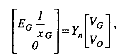
- These actions consist in modelling the node load in the form of its node admittance and determining the Kirchoff's and Ohm's equations matrix comprising the determined synchronous reactances x G of generator G and the complex voltage values determined earlier for 100 % load.
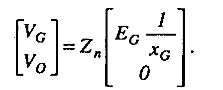
- Y n is the node admittance matrix.
- node impedance matrix Z n is determined as the inverse of matrix Y n and after transformation the following matrix equation is obtained:
- Equation /7/ presents the curve P-Q as a functional relation between active load P and reactive load Q in a given, analysed receiver node, in a cartesian coordinate system, as in fig. 3.
- the operation of determining the load point is marked in fig. 5 as block 4 .
- identification of the system's nodes is made by comparing the numerical value of the k cr coefficient determined for the given node with the assumed threshold value equal to 0.8, which value assumes a 20% allowance as a safety margin to maintain the node voltage stability.
- the result of the comparison serves to determine whether the analysed node is weak, for instance, when the value k cr ⁇ 0.8, or if the node is strong, when k cr >0.8.
Landscapes
- Engineering & Computer Science (AREA)
- Power Engineering (AREA)
- Supply And Distribution Of Alternating Current (AREA)
Abstract
Description
Preferably the nodal voltage stability coefficient is calculated from this relation:
qcr - is the values of the coordinates of reactive load in the node during critical operating conditions at the voltage stability limit,
pb - is the values of the coordinates of the base point of active load in the analysed node,
a qb - is the values of the coordinates of the base point of reactive load in the analysed node.
Δ IOK - is current increment in the kth node accompanying a load change.
It follows from the equation /3/ that having measured the values of voltages and currents in the kth receiver node before and after voltage variation one can determine the values of node impedance Zkk .
Δ IGi - is the current increment in the ith generator node accompanying load change.
qcr- is the values of coordinates of reactive load in the node during critical operating conditions at the voltage stability limit,
pb - is the values of coordinates of active load base point in the analysed node,
a qb - are the values of coordinates of reactive load base point in the analysed node.
Claims (3)
- A method for the identification of weak and/or strong nodes of an electric power transmission system, which employs known analytical methods appropriate to power flow in nodes and branches of the power system and which analyses functional relations between active and reactive load for this system, characterised in that the electric parameters characterising the nodes and branches of the power system are subjected to computational treatment in order to obtain power flow equations in all nodes of the system at assumed 100 percent system load, which treatment is used to calculate complex voltage values in those nodes, and thereafter the earth is taken as a reference node, and the node impedance values for all the system's nodes are calculated, which values are then used to construct a curve /P-Q/ showing the functional relation between reactive load /Q/ and active load /P/ of the system, and then for each node individually the nodal coefficient of voltage stability is determined as the relative distance between the base load point of that node and the critical point on the curve /P-Q/ which is situated most closely to the base point, whereupon the numerical value of that coefficient is compared with a threshold value considered to be a safe margin to maintain voltage stability for the given node, and on the basis of that comparison, the analysed node is identified as weak or strong.
- The method according to claim 1, characterised in that the nodal coefficient of voltage stability /kcr / is calculated from this relation:
qcr - is the values of reactive load coordinates in the node during critical operating conditions at voltage stability limits,
pb - is the values of the coordinates of the base point of active load in the analised node,
and qb - is the values of the coordinates of the base point of reactive load in the analised node. - The method according to claim 1 or 2, characterised in that the analysed node is considered weak where the value of the nodal stability coefficient /kcr / is less than or equal to 0.8 or it is considered strong when the value of the nodal stability coefficient /kcr / is more than 0.8.
Applications Claiming Priority (2)
| Application Number | Priority Date | Filing Date | Title |
|---|---|---|---|
| PL351292A PL199780B1 (en) | 2001-12-20 | 2001-12-20 | Method of identifying weak and/or strong electric power distribution centres within a power distribution system |
| PL35129201 | 2001-12-20 |
Publications (2)
| Publication Number | Publication Date |
|---|---|
| EP1324457A2 true EP1324457A2 (en) | 2003-07-02 |
| EP1324457A3 EP1324457A3 (en) | 2004-12-15 |
Family
ID=20079603
Family Applications (1)
| Application Number | Title | Priority Date | Filing Date |
|---|---|---|---|
| EP02406097A Withdrawn EP1324457A3 (en) | 2001-12-20 | 2002-12-13 | A method of the identification of weak and/or strong nodes of an electric power system |
Country Status (3)
| Country | Link |
|---|---|
| US (1) | US6904372B2 (en) |
| EP (1) | EP1324457A3 (en) |
| PL (1) | PL199780B1 (en) |
Cited By (5)
| Publication number | Priority date | Publication date | Assignee | Title |
|---|---|---|---|---|
| CN102593820A (en) * | 2011-12-22 | 2012-07-18 | 河海大学 | Continuation power flow algorithm considering field current constraint and armature current constraint of power generator |
| CN103823998A (en) * | 2014-03-19 | 2014-05-28 | 国家电网公司 | Weak cross section determination method taking influence of network topology changes on power transmission capacity into consideration |
| WO2014076011A3 (en) * | 2012-11-15 | 2014-07-10 | Siemens Aktiengesellschaft | Method for the computer-aided control of the power in an electrical grid |
| CN111758195A (en) * | 2019-01-28 | 2020-10-09 | 深圳大学 | A Symmetric Method for Obtaining the Branch Current Component of Source Loads in AC Power Networks |
| CN112260273A (en) * | 2020-10-13 | 2021-01-22 | 武汉大学 | Electric power system weak node visual identification method based on all-pure embedding method |
Families Citing this family (16)
| Publication number | Priority date | Publication date | Assignee | Title |
|---|---|---|---|---|
| US7816927B2 (en) * | 2007-07-27 | 2010-10-19 | British Columbia Hydro And Power Authority | Method and system for real time identification of voltage stability via identification of weakest lines and buses contributing to power system collapse |
| CN100523840C (en) * | 2007-09-17 | 2009-08-05 | 重庆大学 | Process for real time recognizing voltage stability of electrified wire netting trough recognizing weak links of electric network |
| US9563722B2 (en) | 2012-11-13 | 2017-02-07 | Gridquant, Inc. | Sigma algebraic approximants as a diagnostic tool in power networks |
| CN103647284B (en) * | 2013-10-22 | 2016-04-06 | 上海交通大学 | A kind of voltage stabilization Forecasting Methodology of discontinuity surface problem when solving list |
| CN104995810B (en) * | 2014-11-18 | 2017-07-07 | 深圳大学 | The acquisition methods of the same symmetric power transmission coefficient for becoming of source lotus in AC power grid |
| JP6726959B2 (en) * | 2015-12-16 | 2020-07-22 | 株式会社日立製作所 | Voltage stability monitoring device and method |
| CN107093904B (en) * | 2016-02-18 | 2020-04-14 | 中国电力科学研究院 | Selection method of reactive power compensation action point in distribution network based on random matrix spectrum analysis |
| CN106682407B (en) * | 2016-12-19 | 2019-05-31 | 国网上海市电力公司 | Voltage Stability Evaluation Method Based on Thevenin Equivalent and Branch Transmission Power Limit |
| CN109257946B (en) * | 2017-05-15 | 2021-10-29 | 深圳大学 | Lossless Eccentricity Method for Obtaining Power Transfer Coefficients of DC Power Networks |
| WO2018209481A1 (en) * | 2017-05-15 | 2018-11-22 | 深圳大学 | Lossless symmetric method for obtaining power transmission coefficient of direct-current power grid |
| WO2018209477A1 (en) * | 2017-05-15 | 2018-11-22 | 深圳大学 | Balanced conductance compensation-type eccentricity method for obtaining power transmission coefficient of direct-current power grid |
| US11366175B2 (en) | 2019-01-28 | 2022-06-21 | Shenzhen University | Linear asymmetric method for examining branch-outage-type steady-state security of AC power networks |
| CN109995022A (en) * | 2019-01-31 | 2019-07-09 | 国网河南省电力公司 | A kind of power grid Short-term Voltage Stability appraisal procedure and system |
| CN113690928B (en) * | 2021-07-16 | 2024-08-13 | 国电南瑞科技股份有限公司 | A method and system for improving voltage stability margin of power system containing new energy |
| CN118508421B (en) * | 2024-05-15 | 2025-04-22 | 山东大学 | Node partitioning method and system considering load transient coupling and voltage similarity |
| CN118970890A (en) * | 2024-07-22 | 2024-11-15 | 铜陵昊盛商贸有限公司 | A power system optimization method based on big data |
Family Cites Families (3)
| Publication number | Priority date | Publication date | Assignee | Title |
|---|---|---|---|---|
| US5796628A (en) | 1995-04-20 | 1998-08-18 | Cornell Research Foundation, Inc. | Dynamic method for preventing voltage collapse in electrical power systems |
| US5745368A (en) * | 1996-03-29 | 1998-04-28 | Siemens Energy & Automation, Inc. | Method for voltage stability analysis of power systems |
| ES2320310T3 (en) | 2000-03-10 | 2009-05-21 | Abb Schweiz Ag | METHOD AND DEVICE FOR EVALUATING THE STABILITY OF AN ELECTRICAL TRANSMISSION NETWORK. |
-
2001
- 2001-12-20 PL PL351292A patent/PL199780B1/en unknown
-
2002
- 2002-12-13 EP EP02406097A patent/EP1324457A3/en not_active Withdrawn
- 2002-12-19 US US10/322,585 patent/US6904372B2/en not_active Expired - Fee Related
Cited By (10)
| Publication number | Priority date | Publication date | Assignee | Title |
|---|---|---|---|---|
| CN102593820A (en) * | 2011-12-22 | 2012-07-18 | 河海大学 | Continuation power flow algorithm considering field current constraint and armature current constraint of power generator |
| CN102593820B (en) * | 2011-12-22 | 2014-01-22 | 河海大学 | Continuation power flow algorithm considering field current constraint and armature current constraint of power generator |
| WO2014076011A3 (en) * | 2012-11-15 | 2014-07-10 | Siemens Aktiengesellschaft | Method for the computer-aided control of the power in an electrical grid |
| CN104769802A (en) * | 2012-11-15 | 2015-07-08 | 西门子公司 | Method for the computer-aided control of the power in an electrical grid |
| US9948103B2 (en) | 2012-11-15 | 2018-04-17 | Siemens Aktiengesellschaft | Method for the computer-aided control of the power in an electrical grid |
| CN103823998A (en) * | 2014-03-19 | 2014-05-28 | 国家电网公司 | Weak cross section determination method taking influence of network topology changes on power transmission capacity into consideration |
| CN103823998B (en) * | 2014-03-19 | 2017-05-10 | 国家电网公司 | Weak cross section determination method taking influence of network topology changes on power transmission capacity into consideration |
| CN111758195A (en) * | 2019-01-28 | 2020-10-09 | 深圳大学 | A Symmetric Method for Obtaining the Branch Current Component of Source Loads in AC Power Networks |
| CN111758195B (en) * | 2019-01-28 | 2023-09-15 | 深圳大学 | Symmetric method for obtaining branch mean square current components of source loads in AC power grids |
| CN112260273A (en) * | 2020-10-13 | 2021-01-22 | 武汉大学 | Electric power system weak node visual identification method based on all-pure embedding method |
Also Published As
| Publication number | Publication date |
|---|---|
| PL199780B1 (en) | 2008-10-31 |
| US6904372B2 (en) | 2005-06-07 |
| PL351292A1 (en) | 2003-06-30 |
| US20030139887A1 (en) | 2003-07-24 |
| EP1324457A3 (en) | 2004-12-15 |
Similar Documents
| Publication | Publication Date | Title |
|---|---|---|
| EP1324457A2 (en) | A method of the identification of weak and/or strong nodes of an electric power system | |
| EP1172660B9 (en) | Method and device for fault location in distribution networks | |
| Moghavvemi et al. | Power system security and voltage collapse: a line outage based indicator for prediction | |
| Wang et al. | A revised branch current-based distribution system state estimation algorithm and meter placement impact | |
| US8108184B2 (en) | Methods and systems for power systems analysis: a non-iterative state solver/estimator for power systems operation and control | |
| EP2927700B1 (en) | Method for monitoring system variables of a distribution or transmission grid | |
| Larsson et al. | Real-time voltage stability assessment of transmission corridors | |
| US6420876B1 (en) | Fault location in a medium-voltage network | |
| Thukaram et al. | A robust three-phase state estimation algorithm for distribution networks | |
| CN110783918A (en) | An Algorithm for State Estimation and Solving of Three-phase Intervals of Distribution Based on Linear Model | |
| US7233153B2 (en) | Method and system for determining location of phase-to-earth fault | |
| US6529010B1 (en) | Location of fault on series-compensated power transmission lines | |
| Nunes et al. | Impedance-based fault location formulation for unbalanced primary distribution systems with distributed generation | |
| Aam et al. | Design of the measurement system for state estimation in the Norwegian high-voltage transmission network | |
| Chihota et al. | Transform for probabilistic voltage computation on distribution feeders with distributed generation | |
| EP1324458B1 (en) | A method of the identification of weak and/or strong branches of an electric power transmission system | |
| JP2005057821A (en) | Distribution system analysis support apparatus and analysis support method | |
| CN113139295A (en) | Method and system for estimating comprehensive state of power system | |
| Kandenkavil et al. | Performance analysis of optimization based static distribution state estimation techniques | |
| Mandich et al. | Optimal pmu placement using stochastic methods | |
| CN119543042A (en) | A short circuit reverse sequence protection method and related equipment for three-phase alternating current | |
| Abbagouni et al. | Loss allocation in three phase unbalanced distribution network using current summation approach | |
| Rahman et al. | Determination of transmission line power transfer capabilities using temperature dependent continuation power flow | |
| Allella et al. | Transient stability probability assessment and statistical estimation | |
| Carpinelli et al. | Probabilistic short-circuit analysis in unbalanced three-phase power systems |
Legal Events
| Date | Code | Title | Description |
|---|---|---|---|
| PUAI | Public reference made under article 153(3) epc to a published international application that has entered the european phase |
Free format text: ORIGINAL CODE: 0009012 |
|
| AK | Designated contracting states |
Designated state(s): AT BE BG CH CY CZ DE DK EE ES FI FR GB GR IE IT LI LU MC NL PT SE SI SK TR |
|
| AX | Request for extension of the european patent |
Extension state: AL LT LV MK RO |
|
| PUAL | Search report despatched |
Free format text: ORIGINAL CODE: 0009013 |
|
| RIC1 | Information provided on ipc code assigned before grant |
Ipc: 7H 02J 3/24 B Ipc: 7H 02J 3/00 A |
|
| AK | Designated contracting states |
Kind code of ref document: A3 Designated state(s): AT BE BG CH CY CZ DE DK EE ES FI FR GB GR IE IT LI LU MC NL PT SE SI SK TR |
|
| AX | Request for extension of the european patent |
Extension state: AL LT LV MK RO |
|
| 17P | Request for examination filed |
Effective date: 20050507 |
|
| AKX | Designation fees paid |
Designated state(s): AT BE BG CH CY CZ DE DK EE ES FI FR GB GR IE IT LI LU MC NL PT SE SI SK TR |
|
| GRAP | Despatch of communication of intention to grant a patent |
Free format text: ORIGINAL CODE: EPIDOSNIGR1 |
|
| RIN1 | Information on inventor provided before grant (corrected) |
Inventor name: SOBIERAJSKI, MARIAN Inventor name: FULCZYK, MAREK Inventor name: BERTSCH, JOACHIM |
|
| STAA | Information on the status of an ep patent application or granted ep patent |
Free format text: STATUS: THE APPLICATION IS DEEMED TO BE WITHDRAWN |
|
| 18D | Application deemed to be withdrawn |
Effective date: 20130403 |