EP1324336A1 - Record medium, its recorder, its recording method, its reproducing apparatus, and its reproducing apparatus - Google Patents
Record medium, its recorder, its recording method, its reproducing apparatus, and its reproducing apparatus Download PDFInfo
- Publication number
- EP1324336A1 EP1324336A1 EP01970260A EP01970260A EP1324336A1 EP 1324336 A1 EP1324336 A1 EP 1324336A1 EP 01970260 A EP01970260 A EP 01970260A EP 01970260 A EP01970260 A EP 01970260A EP 1324336 A1 EP1324336 A1 EP 1324336A1
- Authority
- EP
- European Patent Office
- Prior art keywords
- data
- encoded
- recording
- encoded data
- bit
- Prior art date
- Legal status (The legal status is an assumption and is not a legal conclusion. Google has not performed a legal analysis and makes no representation as to the accuracy of the status listed.)
- Withdrawn
Links
Images


Classifications
-
- G—PHYSICS
- G11—INFORMATION STORAGE
- G11B—INFORMATION STORAGE BASED ON RELATIVE MOVEMENT BETWEEN RECORD CARRIER AND TRANSDUCER
- G11B27/00—Editing; Indexing; Addressing; Timing or synchronising; Monitoring; Measuring tape travel
- G11B27/10—Indexing; Addressing; Timing or synchronising; Measuring tape travel
- G11B27/34—Indicating arrangements
-
- G—PHYSICS
- G11—INFORMATION STORAGE
- G11B—INFORMATION STORAGE BASED ON RELATIVE MOVEMENT BETWEEN RECORD CARRIER AND TRANSDUCER
- G11B20/00—Signal processing not specific to the method of recording or reproducing; Circuits therefor
- G11B20/10—Digital recording or reproducing
-
- G—PHYSICS
- G11—INFORMATION STORAGE
- G11B—INFORMATION STORAGE BASED ON RELATIVE MOVEMENT BETWEEN RECORD CARRIER AND TRANSDUCER
- G11B20/00—Signal processing not specific to the method of recording or reproducing; Circuits therefor
- G11B20/10—Digital recording or reproducing
- G11B20/10009—Improvement or modification of read or write signals
-
- G—PHYSICS
- G11—INFORMATION STORAGE
- G11B—INFORMATION STORAGE BASED ON RELATIVE MOVEMENT BETWEEN RECORD CARRIER AND TRANSDUCER
- G11B20/00—Signal processing not specific to the method of recording or reproducing; Circuits therefor
- G11B20/10—Digital recording or reproducing
- G11B20/10009—Improvement or modification of read or write signals
- G11B20/10046—Improvement or modification of read or write signals filtering or equalising, e.g. setting the tap weights of an FIR filter
- G11B20/10055—Improvement or modification of read or write signals filtering or equalising, e.g. setting the tap weights of an FIR filter using partial response filtering when writing the signal to the medium or reading it therefrom
-
- G—PHYSICS
- G11—INFORMATION STORAGE
- G11B—INFORMATION STORAGE BASED ON RELATIVE MOVEMENT BETWEEN RECORD CARRIER AND TRANSDUCER
- G11B20/00—Signal processing not specific to the method of recording or reproducing; Circuits therefor
- G11B20/10—Digital recording or reproducing
- G11B20/10009—Improvement or modification of read or write signals
- G11B20/10046—Improvement or modification of read or write signals filtering or equalising, e.g. setting the tap weights of an FIR filter
- G11B20/10212—Improvement or modification of read or write signals filtering or equalising, e.g. setting the tap weights of an FIR filter compensation for data shift, e.g. pulse-crowding effects
-
- G—PHYSICS
- G11—INFORMATION STORAGE
- G11B—INFORMATION STORAGE BASED ON RELATIVE MOVEMENT BETWEEN RECORD CARRIER AND TRANSDUCER
- G11B20/00—Signal processing not specific to the method of recording or reproducing; Circuits therefor
- G11B20/10—Digital recording or reproducing
- G11B20/12—Formatting, e.g. arrangement of data block or words on the record carriers
- G11B20/1217—Formatting, e.g. arrangement of data block or words on the record carriers on discs
-
- G—PHYSICS
- G11—INFORMATION STORAGE
- G11B—INFORMATION STORAGE BASED ON RELATIVE MOVEMENT BETWEEN RECORD CARRIER AND TRANSDUCER
- G11B20/00—Signal processing not specific to the method of recording or reproducing; Circuits therefor
- G11B20/10—Digital recording or reproducing
- G11B20/12—Formatting, e.g. arrangement of data block or words on the record carriers
- G11B20/1217—Formatting, e.g. arrangement of data block or words on the record carriers on discs
- G11B20/1258—Formatting, e.g. arrangement of data block or words on the record carriers on discs where blocks are arranged within multiple radial zones, e.g. Zone Bit Recording or Constant Density Recording discs, MCAV discs, MCLV discs
-
- G—PHYSICS
- G11—INFORMATION STORAGE
- G11B—INFORMATION STORAGE BASED ON RELATIVE MOVEMENT BETWEEN RECORD CARRIER AND TRANSDUCER
- G11B20/00—Signal processing not specific to the method of recording or reproducing; Circuits therefor
- G11B20/10—Digital recording or reproducing
- G11B20/14—Digital recording or reproducing using self-clocking codes
- G11B20/1403—Digital recording or reproducing using self-clocking codes characterised by the use of two levels
-
- G—PHYSICS
- G11—INFORMATION STORAGE
- G11B—INFORMATION STORAGE BASED ON RELATIVE MOVEMENT BETWEEN RECORD CARRIER AND TRANSDUCER
- G11B20/00—Signal processing not specific to the method of recording or reproducing; Circuits therefor
- G11B20/10—Digital recording or reproducing
- G11B20/14—Digital recording or reproducing using self-clocking codes
- G11B20/1403—Digital recording or reproducing using self-clocking codes characterised by the use of two levels
- G11B20/1423—Code representation depending on subsequent bits, e.g. delay modulation, double density code, Miller code
- G11B20/1426—Code representation depending on subsequent bits, e.g. delay modulation, double density code, Miller code conversion to or from block codes or representations thereof
-
- G—PHYSICS
- G11—INFORMATION STORAGE
- G11B—INFORMATION STORAGE BASED ON RELATIVE MOVEMENT BETWEEN RECORD CARRIER AND TRANSDUCER
- G11B7/00—Recording or reproducing by optical means, e.g. recording using a thermal beam of optical radiation by modifying optical properties or the physical structure, reproducing using an optical beam at lower power by sensing optical properties; Record carriers therefor
- G11B7/007—Arrangement of the information on the record carrier, e.g. form of tracks, actual track shape, e.g. wobbled, or cross-section, e.g. v-shaped; Sequential information structures, e.g. sectoring or header formats within a track
- G11B7/00745—Sectoring or header formats within a track
-
- H—ELECTRICITY
- H03—ELECTRONIC CIRCUITRY
- H03M—CODING; DECODING; CODE CONVERSION IN GENERAL
- H03M5/00—Conversion of the form of the representation of individual digits
- H03M5/02—Conversion to or from representation by pulses
- H03M5/04—Conversion to or from representation by pulses the pulses having two levels
- H03M5/14—Code representation, e.g. transition, for a given bit cell depending on the information in one or more adjacent bit cells, e.g. delay modulation code, double density code
- H03M5/145—Conversion to or from block codes or representations thereof
-
- G—PHYSICS
- G11—INFORMATION STORAGE
- G11B—INFORMATION STORAGE BASED ON RELATIVE MOVEMENT BETWEEN RECORD CARRIER AND TRANSDUCER
- G11B20/00—Signal processing not specific to the method of recording or reproducing; Circuits therefor
- G11B20/10—Digital recording or reproducing
- G11B20/12—Formatting, e.g. arrangement of data block or words on the record carriers
- G11B20/1217—Formatting, e.g. arrangement of data block or words on the record carriers on discs
- G11B2020/1218—Formatting, e.g. arrangement of data block or words on the record carriers on discs wherein the formatting concerns a specific area of the disc
- G11B2020/1222—ECC block, i.e. a block of error correction encoded symbols which includes all parity data needed for decoding
-
- G—PHYSICS
- G11—INFORMATION STORAGE
- G11B—INFORMATION STORAGE BASED ON RELATIVE MOVEMENT BETWEEN RECORD CARRIER AND TRANSDUCER
- G11B20/00—Signal processing not specific to the method of recording or reproducing; Circuits therefor
- G11B20/10—Digital recording or reproducing
- G11B20/12—Formatting, e.g. arrangement of data block or words on the record carriers
- G11B2020/1264—Formatting, e.g. arrangement of data block or words on the record carriers wherein the formatting concerns a specific kind of data
- G11B2020/1265—Control data, system data or management information, i.e. data used to access or process user data
- G11B2020/1287—Synchronisation pattern, e.g. VCO fields
-
- G—PHYSICS
- G11—INFORMATION STORAGE
- G11B—INFORMATION STORAGE BASED ON RELATIVE MOVEMENT BETWEEN RECORD CARRIER AND TRANSDUCER
- G11B2220/00—Record carriers by type
- G11B2220/20—Disc-shaped record carriers
- G11B2220/25—Disc-shaped record carriers characterised in that the disc is based on a specific recording technology
- G11B2220/2525—Magneto-optical [MO] discs
-
- G—PHYSICS
- G11—INFORMATION STORAGE
- G11B—INFORMATION STORAGE BASED ON RELATIVE MOVEMENT BETWEEN RECORD CARRIER AND TRANSDUCER
- G11B7/00—Recording or reproducing by optical means, e.g. recording using a thermal beam of optical radiation by modifying optical properties or the physical structure, reproducing using an optical beam at lower power by sensing optical properties; Record carriers therefor
Definitions
- the present invention relates to a recording medium in which digital data are recorded, a recording apparatus, a recording method, a reproducing apparatus and a reproduction method for such a recording medium.
- Fig. 12 shows a magneto-optic disk of a recording format which utilizes the (1-7) encoding scheme which is generally used.
- Part (a) of Fig. 12 schematically shows an overall structure of an optical disk according to a conventional example.
- a magneto-optic disk 1201 comprises a spiral track which runs from an inner round toward an outer round of the magneto-optic disk.
- the recording track is divided by pre-pit areas (header areas) 1203, which extend in the radius direction of the magneto-optic disk, into a plurality of data recording areas 1202.
- the pre-pit areas (header areas) 1203 contain pre-formatted data which are generated as a plurality of pre-pits, and the pre-formatted data constitute a header portion having 63 bytes.
- the header portion which is recorded in the pre-pit area 1203, a GAP which is recorded in the data recording area 1202 and the like are joined together, thereby forming one sector (part (b) of Fig. 12).
- the header portion 1203 having 63 bytes comprises a sector mark (SM) 1210 having eight bytes which is indicative of the top of the sector, a VFO1 (Variable Frequency Oscillator, 1211) having 26 bytes and a VFO2 (1214) having 16 bytes which are for generating a synchronous clock which is used to reproduce an ID portion, AMs (1212 and 1215) having one byte, an ID1 (1213) having five bytes and an ID2 (1216) having five bytes which contain address information regarding the sector, and a postamble (PA, 1217) having one byte, and data are generated as the pre-pits.
- SM sector mark
- VFO1 Very Frequency Oscillator, 1211
- VFO2 (1214) having 16 bytes which are for generating a synchronous clock which is used to reproduce an ID portion
- AMs (1212 and 1215) having one byte
- an ID1 (1213) having five bytes
- an ID2 (1216) having five bytes which contain
- the data recording area 1202 contains a GAP (1204) having eight bytes, a VFO3 (1205) having 27 bytes, a Sync (synchronization, 1206) having four bytes, a data field (1207) having 2458 bytes, a postamble (suffix data, PA, 1208) having one byte and a buffer portion (1209) having 23 bytes, and data are recorded as a recording film which exhibits vertical magnetic anisotropy is magnetized.
- the VFO3 (1205) is a signal having a repetitive constant pattern, and used to synchronize a clock which is to read out data which are recorded in the data field 1207.
- the Sync 1206 is data which are used to synchronize a byte of data which are recorded in the data field 1207 which follows the Sync 1206.
- the Sync 1206 may contain data which are for encoding or decoding of top data which are recorded in the data field 1207.
- Resynchronization signals (ReSync signals) are repeatedly inserted at constant intervals between thus encoded pieces of data. Even if there is an out-of-synch attributed to a defect or the like in the disk, it is possible to recover synchronization by means of the re-synchronization signals.
- the postamble (suffix data) 1208 is a signal for decoding last data representing a recording signal encoded by the (1-7) encoding scheme, and is 1-byte data. Owing to the postamble 1208, encoding and decoding by the (1-7) encoding scheme ends within the sector.
- the buffer portion 1209 is disposed to absorb a variation caused by rotations of a motor, jittering of a recording reference clock, etc.
- a phase error regarding a recording position attributed to a rotation-induced variation during recording is absorbed by the VFO3 (1205), the re-synchronization signal inserted in the data field 1207 and the buffer portion (1209).
- the data field 1207 and other signals have a data volume which is an integer multiple of one byte.
- a problem occurs such as a waveform interference, a distorted waveform due to a low-frequency component, a phase lock failure of a data clock during reproduction, or the like.
- an encoding scheme which ensures that post-conversion encoded data do not contain a bit string of the same values in a row over a certain length or a longer length (so that a certain number of zeroes or more zeroes will not appear successively, for instance), namely, a run length limit encoding scheme which is an encoding scheme which restricts a run length (the length of the bit string of the successive same values).
- the (1-7) encoding scheme is one of encoding schemes which restrict a run length, according to which in post-conversion encoded data, the value 1 does not appear in a row (there are always zeroes before and after one) and the maximum number of successive pieces of the value 0 (bit count) is limited to seven (The number of successive zeroes is one through seven).
- Encoding rules of the (1-7) encoding scheme will now be described with reference to a conversion table in Table 1.
- 2-bit input data are encoded into 3-bit encoded data.
- This encoding conversion rule is determined by a combination of 1-bit encoded data generated through immediately precedent encoding, 2-bit input data to be encoded (input data which are an encoding target) and 2-bit input data which follow the input data to be encoded (data to be encoded next).
- 3-bit encoded data are decoded into 2-bit data using a reverse conversion table in Table 2.
- the decoding conversion rule is determined by a combination of last two bits of 3-bit encoded data which was a decoding target immediately before, 3-bit encoded data to be decoded (input data which are a decoding target) and 2-bit encoded data which follow the encoded data which are to be decoded (encoded data which are to be decoded next).
- the Sync 1206 containing prefix encoded data is placed before the data portion 1207 of each sector so as to decode the top data, while the postamble (suffix data) 1208 is placed after the data portion 1207 so as to decode the last data.
- a data string having a predetermined length is uniquely converted into an encoded data string having a predetermined length with reference to a predetermined conversion table during encoding
- an encoded data string having a predetermined length is uniquely converted into a data string having a predetermined length with reference to a predetermined conversion table during decoding.
- ASMO the standard called ASMO requires to use the NRZI+ method which is one type of such encoding schemes, to thereby record in divided data recording areas in a distributed manner.
- a resolution for reproduction of a signal is determined almost by the wavelength ⁇ of reproduction light and the numerical aperture (NA) of an object lens, and a pit pitch at a detection limit is approximately ⁇ /(2 ⁇ NA).
- NA numerical aperture
- recording mediums, reproduction methods and the like are improved in an effort to enhance a recording density of information.
- magneto-optic recording mediums magnetic-optic disks
- various types of ideas for improvement in recording density of information have been proposed.
- a conventional optical disk In a conventional optical disk, grooves, areas between the grooves and the like are used as recording tracks. Since a signal for tracking control is obtained from these grooves, there is a restriction upon an optical resolution which is for a track pitch to obtain a tracking guide signal from these grooves. Because of this, it is very difficult to reduce the track pitch. Where a conventional recording and reproducing method is used, when a track pitch is reduced, cross talk from an adjacent track makes reproduction difficult. Since a track pitch restricted by cross talk is approximately equal to a lower limit track pitch which is for obtaining a tracking signal from a groove, this is not a big problem in a conventional optical disk.
- a recording density in address portions is 0.5 ⁇ m/bit and a recording density in data portions (areas where data are recorded) is similarly about 0.5 ⁇ m/bit.
- address redundancy a proportion of address data to the entire data (which is called "address redundancy"
- a recording density in an address portion is 0.5 ⁇ m/bit
- a recording density in a data portion is about 0.1 ⁇ m/bit
- the poor format efficiency is attributed to a format structure of a conventional optical disk in which one address is added to one sector.
- the sample servo method is essential as a tracking method as described in relation to the conventional techniques.
- data in a sector which is a unit for one rewriting is divided and recorded over a plurality of segments.
- An optical disk drive using a conventional sample servo method for the purpose of realizing such division and recording of data, uses a modulation code which permits to execute modulation and demodulation regardless of the dependency upon precedent and subsequent data during recording and reproduction.
- Examples are the NRZI modulation method in the HS standard, the NRZI+ modulation method in the ASMO standard, the 4-15 modulation method as a position modulation method, etc. Modulation codes for these are codes under no run length restriction, or codes under a very long run length restriction even if the codes are under restriction.
- a DWDD reproduction signal is generated as a magnetic wall toward the traveling direction of a light beam.
- a signal generated in accordance with the movements of the magnetic walls is called a ghost signal, and significantly disturbs reproduction of data.
- the probability of ghost signal generation becomes high when the length of a recording mark reaches a certain level or more.
- the length of a recording mark, which is to be recorded in a DWDD recording film is as short as possible.
- codes under a run length restriction such as 1-7 codes and 2-7 codes are therefore suitable.
- a limit on a linear recording density is determined by a limit over the length of a mark which can be recorded and reproduced in a DWDD-type recording/reproduction film. This is because the intensity of a DWDD-type reproduction signal is not dependent upon an optical resolution of reproduction light at all.
- a limit over the length of a mark which can be recorded and reproduced in a DWDD-type recording/reproduction film is normally about 0.1 ⁇ m.
- a linear recording density is 0.075 ⁇ m/bit when the minimum length of a mark which can be recorded is 0.1 ⁇ m
- a linear recording density is 0.067 ⁇ m/bit when the mark length is 0.1 ⁇ m, thereby shortening the length per bit than the minimum recording mark length and improving a recording density.
- the standard known as ASMO described in relation to the conventional techniques requires to divide a sector which is a unit for one rewriting into a plurality of recording areas for NRZI+ encoding and recording. During this NRZI+ encoding, a run length restriction is very long and it is accordingly difficult to extract a demodulation clock from a reproduction signal.
- the ASMO standard therefore uses an external clock system which generates recording/reproduction clocks from pits engraved in advance in a disk. According to a conventional sample servo method which is generally used, too, recording/reproduction clocks are generated from pits engraved in advance in a disk, in a similar fashion.
- a reproduction limit is an optical limit of a light beam.
- the limit is normally about 0.5 ⁇ m.
- a reproduction limit of a DWDD signal, which is read out by a super resolution reproduction method is about 0.1 ⁇ m which is as five times high as or higher, a reproduction clock extracted at a reproduction limit of 0.5 ⁇ m is insufficient as a clock for reproduction of a 0.1 ⁇ m-mark, and thus, the accuracy of clocks runs short.
- a conventional optical disk complying with the ASMO standard or a sample servo scheme is on an assumption that a reproduction clock is extracted from a clock pit, and a modulation code uses a modulation method with which it is not possible to extract a reproduction clock from a reproduction signal.
- a conventional sample servo method or the like which requires to divide a sector which is a unit for rewriting into a plurality of recording areas, it is not possible to execute recording or reproduction at a high density using super resolution such as that of the DWDD type.
- a run length limit encoding scheme (which may be the (1-7) encoding scheme or the like for instance), prevent ghost over a long mark or a bit reproduction error over a single mark, and extract a reproduction clock from an inversion part of a reproduction signal which is generated as a result of the run length restriction mentioned above.
- a sample servo method for the purpose of improving a track density as described above, it is necessary to divide a sector which is a unit for rewriting into segments which are a plurality of areas and record.
- an effective data recording density (a density which is obtained by converting a data volume of recording data per unit surface area (channel bit count) into a data volume of pre-encoding data (input data)) of this recording medium largely decreases.
- a track density is improved by a sample servo method and a sector which is a unit for rewriting is divided into segments which are a plurality of areas.
- a data recording area which is in the vicinity of a pit area which is for detection of a tracking servo signal
- birefringence changes in the data recording area because of an influence by a pre-pit area, thereby the envelope of a reproduction signal changes (This envelope variation will be hereinafter referred to as a skew distortion.).
- a skew distortion makes it difficult to binarize a reproduction signal (i.e., to digitize one bit) an area near a pre-pit area accordingly becomes unusable as a data recording area, which serves as a cause of a deterioration in recording density of the high-density optical disk.
- the skew distortion changes substantially because of a phase difference between P-polarized light and S-polarized light of an optical pick-up which executes reproduction, and therefore, in order to perform reproduction with little skew distortion, it is necessary to ensure that the phase difference of the optical pick remains within ⁇ 5 degrees. This also serves as a difficulty against commercialization of a high-density optical disk.
- the present invention aims at providing means which encodes data of a sector which is a unit for rewriting under a run length restriction, divides into a plurality of areas and records and accordingly providing a high-density optical disk.
- a recording and reproducing medium in which recording and reproduction are executed by a super resolution reproduction method according to which a data recording area is beyond an optical resolution, the present invention brings about an even more significant effect.
- the present invention also aims at a recording medium in which such data are recorded which makes it easy to accurately binarize a reproduction signal which has a skew distortion (a low-frequency waveform distortion) or a differential signal between two consecutive reproduction signals.
- the first invention is directed to a recording medium, comprising: a pre-pit area comprising pre-pits; and a plurality of data recording areas which are divided by the pre-pit area and in which a data block is recorded which is obtained by dividing one data stream which is formed by encoded data which are encoded by an encoding scheme including a run length limit encoding scheme, wherein in at least one data recording area, data having a predetermined value of at lease one bit are further recorded in front of the data block.
- encoding and decoding complete within one data recording area.
- a conventional recording medium which uses a run length limit encoding scheme has a structure that prefix data, a data block and suffix data are recorded in each data recording area and encoding and decoding end within each data recording area.
- prefix data which may be 001 or the like for instance
- constant data which may be 001 or the like for instance
- the present invention achieves an effect that it is possible to realize a recording medium which has a high effective recording density, owing to continuity between encoded data belonging to each data recording area (e.g., a data recording area in each segment) and encoded data belonging to precedent and subsequent data recording areas.
- addition of small data makes it possible to divide a data volume equivalent to one sector (which is a unit of a chunk of data to be recorded or reproduced, and is one ECC block in an embodiment) for instance into a plurality of segments and record.
- a channel bit count (recordable bit count) of one data recording area e.g., a data recording area in each segment
- the recording medium according to the present invention has a higher level of freedom regarding a format than the conventional recording medium has.
- the present invention achieves an effect that it is possible to realize a recording medium which has a high recording density.
- the present invention achieves an effect that particularly in a recording medium wherein one sector is divided into a number of data recording areas (e.g., a disk-shaped recording medium in which a recording track whose length is one round is divided into 1000 or more data recording areas), a recording medium which has a high effective recording density is realized.
- a recording medium which has a high effective recording density is realized.
- a reproduction signal has a large low-frequency skew distortion. Hence, it is difficult to binarize a reproduction signal which was reproduced in the conventional recording medium.
- the present invention achieves an effect that it is possible to realize a recording medium which permits a reproducing apparatus to accurately binarize a reproduction signal which contains a skew distortion (a low-frequency waveform distortion).
- the section reading "plurality of data recording areas which are divided by the pre-pit area and in which a data block is recorded which is obtained by dividing one data stream which is formed by encoded data which are encoded by an encoding scheme including a run length limit encoding scheme” refers to data streams of encoded data which are encoded by an encoding scheme including a run length limit encoding scheme, which means that a data stream in which adjacent pieces of encoded data are associated with each other is recorded over a plurality of data recording areas.
- encoded data in a precedent data block are used, while for the purpose of decoding encoded data at the end of the data block recorded in the data recording area, encoded data in a subsequent data block are used.
- this data block and the precedent data block belong to different data streams.
- pre-pit is a physical concave or convex portion disposed in a recording medium.
- An example is a pre-pit formed on an optical disk substrate.
- the "run length limit encoding scheme” includes the (1-7) encoding scheme, the (2-7) encoding scheme and the like. In the event that a recording density remains the same, such an encoding scheme generally permits to extend the shortest recording mark longer than a recording density per bit and restricts the longest recording mark, thereby allowing to generate a reference clock for reproduction from a reproduction signal.
- the "recording medium” is any desired medium (any desired recording element, a medium having any desired shape) in which digital data are recorded. Examples are optical disks (including phase-conversion optical disks and magneto-optical disks), magnetic cards and the like.
- the "data having a predetermined value of at lease one bit” may be a known value or a value which is unknown at the time of reproduction. Being “known” means being known at the time of recording of this data or reproduction of this data. For instance, this may be a certain value (0 or 1), data at the last one bit of an immediately precedent data block (The data are known at the time of recording of the 1-bit data.), or data at the last one bit recorded in an immediately precedent data recording area (The data are known at the time of reproduction of the 1-bit data.).
- the channel bit count of the added data is any desired figure which is 1 or larger.
- the second invention is directed to a recording medium, comprising: a pre-pit area comprising pre-pits; and a plurality of data recording areas which are divided by the pre-pit areas and in which a data block is recorded which is obtained by dividing one data stream which is formed by encoded data which are encoded by an encoding scheme including a run length limit encoding scheme, wherein in at least one data recording area, data having the same value as the last one bit of the encoded data in the data recording area which is before the data recording area are further recorded in front of the data block.
- the present invention achieves an effect that it is possible to realize a recording medium which has a high effective recording density, owing to continuity between encoded data belonging to each data recording area and encoded data belonging to precedent and subsequent data recording areas.
- the present invention achieves an effect that it is possible to realize a recording medium which has a high effective recording density.
- the present invention achieves an effect that it is possible to realize a recording medium which permits a reproducing apparatus to accurately binarize a reproduction signal which contains a skew distortion (a low-frequency waveform distortion).
- the present invention achieves an effect that it is possible to realize a recording medium which can be reproduced using a reproducing apparatus which has a simple structure.
- the "data having the same value as the encoded data at the last one bit in the data recording area which is before the data recording area" may have one bit or a plurality of bits (and the plurality of bits are all "the same value as the encoded data at the last one bit").
- the third invention is directed to the recording medium of the first invention, wherein the data block has the encoded data in a data volume which is an integer multiple of 2 if a data volume is converted into a volume of data before being encoded by a run length limit encoding scheme.
- 2-bit input data are converted into three bits, and encoded data are generated in units of three bits (the number of channel bits).
- a data block recorded in the recording medium according to the present invention has a data capacity which is an integer multiple of 2 (The capacity of a data block is expressed as an effective data size as it is before encoded by a run length limit encoding scheme.), it is possible to simplify a control circuit for an encoder which encodes data in units of three channel bits (which correspond to the 2-bit input data) and a decoder which decodes data in units of three channel bits (and it is possible to simplify a processing circuit which is at a joint between adjacent data blocks in particular).
- TRUNC denotes a function for generating a numerical figure which consists only of an integer portion of a numerical figure in parentheses (i.e., for rounding down decimal figures).
- MOD () denotes a function which expresses a remainder which is obtained by division described in ().
- the maximum value of P is seven bits in a conventional recording medium wherein the channel bit count is eight bits for instance, the maximum value of P, when expressed as the number of channel bits, is two channel bits in the recording medium according to the present invention.
- the present invention achieves an effect that it is possible to realize a recording medium which is less wasted and has a high recording density.
- the fourth invention is directed to a recording apparatus, comprising: an encoding unit which generates a plurality of data blocks which are obtained by dividing one data stream which is formed by encoded data which are obtained by encoding input data by an encoding scheme including a run length limit encoding scheme; a data adding unit which adds data having a predetermined value of at lease one bit to the top of at least one of the divided data blocks and generates a data block which contains thus added data; and a recording unit which records the data block which contains thus added data in the recording medium.
- the present invention achieves an effect that it is possible to realize a recording medium which has a high effective recording density, owing to continuity between encoded data belonging to each data recording area and encoded data belonging to precedent and subsequent data recording areas.
- the present invention achieves an effect that it is possible to realize a recording apparatus for recording encoded data at a high effective recording density particularly in a recording medium wherein one sector is divided into a number of data recording areas (e.g., a disk-shaped recording medium in which a recording track whose length is one round is divided into 1000 or more data recording areas).
- a recording apparatus for recording encoded data at a high effective recording density particularly in a recording medium wherein one sector is divided into a number of data recording areas (e.g., a disk-shaped recording medium in which a recording track whose length is one round is divided into 1000 or more data recording areas).
- a reproduction signal since a reproduction signal has a large low-frequency skew distortion in a portion where a beam spot of a light beam has just moved from a pre-pit area to a data recording area, it is difficult to binarize a reproduction signal according to a conventional technique.
- predetermined data are recorded at the beginning of each data recording area.
- the present invention achieves an effect that it is possible to realize a recording apparatus for recording data which, utilizing the added data, is capable of accurately binarizing a reproduction signal even when the reproduction signal has a skew distortion (a low-frequency waveform distortion).
- the "data block which contains thus added data” means data having a predetermined value of at lease one bit and a data block as they are combined with each other.
- the encoding unit may divide input data first to thereby generate a plurality of data blocks, and then encode each data block by an encoding scheme including a run length limit encoding scheme to thereby generate a plurality of data blocks of encoded data.
- the encoding unit may first encode one data stream by an encoding scheme including a run length limit encoding scheme, and then divide thus encoded data stream into a plurality of data blocks.
- the encoding unit may first encode one data stream by a run length limit encoding scheme, then divide thus encoded data stream into a plurality of data blocks, and thereafter convert each data block by other conversion method (such as NRZI conversion).
- the encoding unit according to each invention includes all these structures described above but is not limited to these examples above. This is similar as to the encoding unit according to the fifth invention and the encoding steps according to the eleventh invention and the twelfth invention.
- the encoding unit and the data adding unit may constitute blocks which are independent of and separate from each other, or may have a structure which is the two integrated with each other in such a manner that the two can not be separated from each other.
- the fifth invention is directed to a recording apparatus, comprising: an encoding unit which generates a plurality of data blocks which are obtained by dividing one data stream which is formed by encoded data which are obtained by encoding input data by an encoding scheme including a run length limit encoding scheme; a data adding unit which adds data having the same value as the last one bit of the encoded data in the data block which is before at least one of the divided data blocks to the top of at least one of the divided data blocks and generates a data block which contains thus added data; and a recording unit which records the data block which contains thus added data in the recording medium.
- the present invention achieves an effect that it is possible to realize a recording apparatus which records data in a recording medium which has a high effective recording density, owing to continuity between encoded data belonging to each data recording area and encoded data belonging to precedent and subsequent data recording areas.
- the present invention achieves an effect that it is possible to realize a recording apparatus which records encoded data in a recording medium at a high effective recording density and with a high error correcting capability.
- the present invention achieves an effect that it is possible to realize a recording apparatus which records, in a recording medium data which permit a reproducing apparatus to accurately binarize a reproduction signal which contains a skew distortion (a low-frequency waveform distortion).
- the present invention achieves an effect that it is possible to realize a recording apparatus which records, in a recording medium, data which can be reproduced using a reproducing apparatus which has a simple structure.
- the sixth invention is directed to the recording apparatus of the fourth invention, wherein the data block has the encoded data in a data volume which is an integer multiple of 2 if a data volume is converted into a volume of data before being encoded by a run length limit encoding scheme.
- a data block recorded in the recording medium according to the present invention has a data capacity which is an integer multiple of 2 (The capacity of a data block is expressed as an effective data size as it is before encoded by a run length limit encoding scheme.), it is possible to simplify a control circuit for an encoder which encodes data in units of three channel bits (which correspond to the 2-bit input data) and a decoder which decodes data in units of three channel bits (and it is possible to simplify a processing circuit which is at a joint between adjacent data blocks in particular).
- the present invention achieves an effect that it is possible to realize a recording apparatus having a simple structure which records, in a recording medium, data at a high recording density while avoiding a wasteful use.
- the seventh invention is directed to the recording apparatus of any one of the fourth through the sixth inventions, wherein the encoding unit or the data adding unit adds, after the last piece of the encoded data, data having a predetermined value of n bits (where n is any desired positive integer).
- the recording apparatus therefore requires to add data having a certain value (which may be 001 or the like for instance) after the last encoded data in the data stream.
- n is any desired value.
- data having n bits may be added and recorded after the last data in the data stream, and any desired data having k bits (where k is any desired positive integer) may be further recorded after the data having n bits.
- the eighth invention is directed to a reproducing apparatus, comprising: a reproducing unit which reproduces signals recorded in a recording medium and outputs reproduction signals; a difference detecting unit which generates differential signals which represent a difference between two consecutive ones of the reproduction signals; a binary data generating unit which generates binary data which are binarized based on the differential signals; and a decoding unit which decodes the binary data by a run length limit encoding scheme.
- a reproduction signal has a large low-frequency skew distortion in a portion where a beam spot of a light beam has just moved from a pre-pit area to a data recording area, it is difficult to binarize a reproduction signal according to a conventional technique.
- the reproducing apparatus subtracts two consecutive reproduction signals as they are analog signals for example to thereby generate the differential signal (which is a differential signal between the analog signals), or converts two consecutive reproduction signals into digital signals having a plurality of bits (10-bit data for example) and then generates a differential signal between the two consecutive digital signals having a plurality of bits (which is a differential signal between the plurality of bits).
- the differential signal is thereafter binarized.
- the differential signal between the analog signals or the differential signal between the plurality of bits is generated first, even when the reproduction signals contain a skew distortion (a low-frequency waveform distortion), the skew is cancelled and fails to be contained in the differential signal.
- a skew distortion a low-frequency waveform distortion
- the present invention achieves an effect that it is possible to realize a reproducing apparatus which accurately binarizes a reproduction signal without influenced by a skew.
- the present invention achieves an effect that it is possible to realize a reproducing apparatus which accurately binarizes a reproduction signal without influenced by a skew and simultaneously decodes (inverse conversion) an NRZI-converted reproduction signal.
- the ninth invention is directed to a reproducing apparatus, comprising: a reproducing unit which reproduces, from a recording medium, encoded data which are encoded by an encoding scheme including a run length limit encoding scheme and recorded as they are divided into a plurality of data blocks; and a decoding unit which, using the encoded data of the data block and the encoded data of the next data block, decodes the encoded data of the data block or the next data block.
- the present invention achieves an effect that it is possible to realize a reproducing apparatus which reproduces and decodes encoded data which are recorded in a recording medium at a high effective recording density, owing to continuity between encoded data belonging to each data recording area and encoded data belonging to precedent and subsequent data recording areas.
- a conventional reproducing apparatus which uses a run length limit encoding scheme for instance is capable of only reproducing a signal from a recording medium in which recorded within each data recording area is such a data block which permits decoding to finish only within each data block.
- the present invention achieves an effect that it is possible to realize a reproducing apparatus particularly for a recording medium in which data covering one sector are divided over a number of data recording areas (For example, recording tracks (each having a length equivalent to one round within a disk) in a disk-shaped recording medium are each divided into 1000 or more data recording areas.) and recorded at a high effective recording density.
- the tenth invention is directed to a reproducing apparatus, comprising: a reproducing unit which reproduces and outputs, from each one of a plurality of data recording areas of a recording medium, reproduction signals of data blocks and predetermined data further recorded before the data blocks; a binarizing unit which binarizes the reproduction signals and outputs binary signals; and a decoding unit which combines, in the order of reproduction from the data recording areas, the binary signals of a plurality of the data blocks with each other except for the predetermined data of other data blocks than at least the top data block, and decodes the binary signals thus combined by a run length limit encoding scheme.
- the present invention achieves an effect that it is possible to realize a reproducing apparatus which reproduces and decodes encoded data which are recorded in a recording medium at a high effective recording density, as a data stream encoded by a run length limit encoding scheme is divided into a plurality of data blocks and each data block is recorded in each data recording area.
- a reproduction signal is binarized using predetermined data as in an embodiment for instance, it is possible to binarize the reproduction signal without influenced by a skew.
- the predetermined data is any desired data having one bit or more.
- the decoder unit may decode from a binarized signal, excluding the predetermined data other than in at least the data block located at the top, or the binarizing unit may not binarize these predetermined data (The embodiments are the latter.).
- the eleventh invention is directed to a reproducing apparatus, comprising: a reproducing unit which reproduces a data stream of encoded data which are encoded by an encoding scheme including a run length limit encoding scheme from a recording medium; a counter which counts the number of encoded data of the data stream, the number of encoding processes or the number of decoded data; a last encoded data detecting unit which detects a last encoded data of the data stream based on the value of the counter; and a decoding unit which, when the last encoded data detecting unit detects that a decoding-target encoded data is the last encoded data, decodes the decoding-target encoded data using at least the decoding-target encoded data and data having a constant value.
- the reproducing apparatus decodes the last encoded data using data having a certain value (which are typically data held in the decoder unit) held in the reproducing apparatus.
- the present invention achieves an effect that it is possible to realize a reproducing apparatus which decodes a reproduction signal reproduced from a recording medium in which data for decoding the last encoded data are not recorded.
- the counter and the last encoded data detector unit may directly count the number of encoded data or the like, or indirectly count the number of encoded data. This virtually includes counting of the number of encoded data of the data stream, the number of encoding processes or the number of decoded data.
- 900 reproduction clocks (clocks for encoded data) are generated per segment (including a pre-pit area), encoded data are reproduced with reference to the 111-st through the 890-th reproduction clocks (The first through 110-th and the 891-st through the 900-th clocks are for areas in which data are not recorded (pre-pit areas).), and the 410-th clock is for the last encoded data (Data are recorded from the 111-st through the 410-th clocks.).
- the counter is reset at the 110-th reproduction clock (i.e., becomes zero), and when the value in the counter reaches 300 (the 410-th clock), the last encoded data detector unit detects the last encoded data.
- the last encoded data is detected.
- the twelfth invention is directed to a recording method, comprising: an encoding step of generating a plurality of data blocks which are obtained by dividing one data stream which is formed by encoded data which are obtained by encoding input data by an encoding scheme including a run length limit encoding scheme; a data adding step of adding data having a predetermined value of at lease one bit to the top of at least one of the divided data blocks and generating a data block which contains thus added data; and a recording step of recording the data block which contains thus added data in the recording medium.
- the present invention achieves an effect that it is possible to realize a recording method of recording encoded data in a recording medium at a high effective recording density, owing to continuity between encoded data belonging to each data recording area and encoded data belonging to precedent and subsequent data recording areas.
- the present invention achieves an effect that it is possible to realize a recording method of recording encoded data at a high effective recording density and under a run length limit restriction particularly in a recording medium in which one sector is divided into a number of data recording areas (e.g., a disk-shaped recording medium in which a recording track whose length is one round is divided into 1000 or more data recording areas).
- the recording method according to the present invention requires to record predetermined data at the beginning of each data recording area. Hence, using the reproducing method according to the present invention, it is possible to accurately binarize a reproduction signal utilizing this as in the reproducing method according to an embodiment for example.
- the present invention achieves an effect that it is possible to realize a recording method of recording data which permits accurate binarization of a reproduction signal, owing to use of the added data even when the reproduction signals contain a skew distortion (a low-frequency waveform distortion).
- the thirteenth invention is directed to a recording method, comprising: an encoding step of generating a plurality of data blocks which are obtained by dividing one data stream which is formed by encoded data which are obtained by encoding input data by an encoding scheme including a run length limit encoding scheme; a data adding step of adding data having the same value as the last one bit of the encoded data in the data block which is before at least one of the divided data blocks to the top of at least one of the divided data blocks and generates a data block which contains thus added data; and a recording step of recording the data block which contains thus added data in the recording medium.
- the present invention achieves an effect that it is possible to realize a recording method of recording data in a recording medium at a high effective recording density, owing to continuity between encoded data belonging to each data recording area and encoded data belonging to precedent and subsequent data recording areas.
- the present invention achieves an effect that it is possible to realize a recording method of recording encoded data in a recording medium at a high effective recording density and with a high error correcting capability.
- the present invention achieves an effect that it is possible to realize a recording method of recording, in a recording medium data which permit a reproducing apparatus to accurately binarize a reproduction signal which contains a skew distortion (a low-frequency waveform distortion).
- the fourteenth invention is directed to the recording method of the twelfth invention, wherein the data block has the encoded data in a data volume which is an integer multiple of 2 if a data volume is converted into a volume of data before being encoded by a run length limit encoding scheme.
- a data block recorded in a recording medium by the recording method according to the present invention has a data capacity which is an integer multiple of 2 (The capacity of a data block is expressed as an effective data size as it is before encoded by a run length limit encoding scheme.), it is possible to simplify the encoding process of encoding data in units of three channel bits (which correspond to the 2-bit input data) and the decoding process of decoding data in units of three channel bits (and it is possible to simplify processing over a joint between adjacent data blocks in particular).
- the present invention achieves an effect that it is possible to realize an inexpensive recording method of recording, in a recording medium, data at a high recording density while avoiding a wasteful use.
- the fifteenth invention is directed to the recording method of any one of the twelfth through the fourteenth inventions, wherein at the encoding step or the data adding step, data having a predetermined value of n bits (where n is any desired positive integer) are added after the last piece of the encoded data.
- the recording method according to the present invention requires to add data having a constant value (which may be 1 for instance) after the last encoded data in the data stream. Therefore, it is possible to decode the last encoded data, using a reproducing apparatus.
- the sixteenth invention is directed to a reproduction method, comprising: a reproducing step of reproducing signals recorded in a recording medium and outputting reproduction signals; a difference detecting step of generating differential signals which represent a difference between two consecutive ones of the reproduction signals; a binary data generating step of generating binary data which are binarized based on the differential signals; and a decoding step of decoding the binary data by a run length limit encoding scheme.
- the present invention achieves an effect that it is possible to realize a reproduction method of accurately binarizing a reproduction signal without influenced by a skew.
- the seventeenth invention is directed to a reproduction method, comprising: a reproducing step of reproducing, from a recording medium, encoded data which are encoded by an encoding scheme including a run length limit encoding scheme and recorded as they are divided into a plurality of data blocks; and a decoding step of, using the encoded data of the data block and the encoded data of the next data block, decoding the encoded data of the data block or the next encoded data.
- the present invention achieves an effect that it is possible to realize a reproduction method of reproducing and decoding encoded data which are recorded in a recording medium at a high effective recording density, owing to continuity between encoded data belonging to each data recording area and encoded data belonging to precedent and subsequent data recording areas.
- the present invention achieves an effect that it is possible to realize a reproduction method particularly for a recording medium in which data covering one sector are divided over a number of data recording areas (For example, recording tracks (each having a length equivalent to one round within a disk) in a disk-shaped recording medium are each divided into 1000 or more data recording areas.) and recorded at a high effective recording density.
- the eighteenth invention is directed to a reproduction method, comprising: a reproducing step of reproducing and outputting, from each one of a plurality of data recording areas of a recording medium, reproduction signals of data blocks and predetermined data further recorded before the data blocks; a binarizing step of binarizing the reproduction signals and outputting binary signals; and a decoding step of combining, in the order of reproduction from the data recording areas, the binary signals of a plurality of the data blocks with each other except for the predetermined data of other data blocks than at least the top data block, and decoding the binary signals thus combined by a run length limit encoding scheme.
- the present invention achieves an effect that it is possible to realize a reproduction method of reproducing and decoding encoded data which are recorded in a recording medium at a high effective recording density, as a data stream encoded by a run length limit encoding scheme is divided into a plurality of data blocks and each data block is recorded in each data recording area.
- a reproduction signal is binarized using predetermined data as in an embodiment for instance, it is possible to binarize the reproduction signal without influenced by a skew.
- the nineteenth invention is directed to a reproduction method, comprising: a reproducing step of reproducing, from a recording medium, a data stream of encoded data which are encoded by an encoding scheme including a run length limit encoding scheme; a counting step of counting the number of encoded data of the data stream, the number of encoding processes or the number of decoded data; a last encoded data detecting step of detecting a last encoded data of the data stream based on the value of the counter; and a decoding step of, when the last encoded data detecting unit detects that a decoding-target encoded data is the last encoded data, decoding the decoding-target encoded data while using at least the decoding-target encoded data and data having a constant value.
- the present invention achieves an effect that it is possible to realize a reproduction method of decoding a reproduction signal reproduced from a recording medium in which data for decoding the last encoded data are not recorded.
- Part (a) of Fig. 1 shows a general overall structure of a magneto-optical disk 100 according to the embodiment 1 of the present invention.
- Fig. 1 In part (a) of Fig. 1, denoted at is an optical disk substrate, denoted at 102 is a DWDD recording/reproduction film which permits super resolution reproduction, denoted at 103 is a first recording track, denoted at 104 is a second recording track which is adjacent to the first recording track, denoted at 105 are segments obtained by dividing the first recording track 103 and the second recording track 104 into 1280 pieces, denoted at 106 and 113 are pre-pit areas (pre-formatted areas).
- the pre-formatted areas 106 and 113 comprise clock pits, servo pits for tracking, and address pits which are indicative of position information regarding a disk.
- the first recording track 103 and the second recording track 104 are spiral areas which start and end at the pre-pit areas: When the spiral recording tracks are traced from an inner round toward an outer round of the magneto-optical disk, the second recording track 104 ends at the pre-pit area 113, and the first recording track 103 starts where the second recording track 104 ends (the pre-pit area 113).
- a track pitch of the first recording track 103 and the second recording track 104 is about 0.6 ⁇ m.
- the first recording track 103 and the second recording track 104 which are adjacent to each other are shown as they are extremely enlarged.
- Part (b) of Fig. 1 is a schematic enlarged view of one segment 105.
- a segment which is comprised of one recording track and one pre-pit area
- denoted at 106 is a pre-pit area (pre-formatted area)
- a ditch portion (groove portion) 111 having a length 107 is a recording track (data recording area) for recording data.
- the pre-pit area 106 comprises clock pits 115, wobble pits 108 and 109, and address pits 110 in which address information is distributed one bit each at the beginning of a segment.
- Inter-ditch portions (land portions) 114 having a length 107 magnetically block adjacent ditch portions from each other.
- the clock pits 115 are located at the top of the respective segments. With a frequency-divided signal obtained by dividing an output signal from a voltage controlled oscillator synchronized to a detection signal indicative of the clock pits of the respective segments, it is possible to use the output signal from the voltage controlled oscillator as a synchronization clock for data encoding during recording.
- the output signal from the voltage controlled oscillator is used also as a synchronization clock for a window clock generation circuit which detects the wobble pits 108 and 109 and the address pits 110.
- the paired wobble pits 108 and 109 are located half a track displaced in opposite directions to each other with respect to center lines of the recording tracks 103 and 104, and the polarities of the paired wobble pits 108 and 109 are inverted every round of the recording tracks 103 and 104.
- a tracking error signal is generated based on a difference in terms of the amount of reflected light from said wobble pits 108 and 109, and tracking control of a light beam is performed such that the amounts of reflected light from the wobble pits 108 and 109 will be equal to each other.
- Whether there are the address pits 110 provides one bit of information per segment. 80 pieces of the address pits 110 gathered together make one piece of position information.
- the position information expresses a segment position along a track direction and the radius direction on the magneto-optical disk.
- applications regarding a distributed address format Japanese Patent Application Laid-Open No. 11-021885 and Japanese Patent Application Laid-Open No. 11-329265) describe the details.
- a master optical disk is processed by etching with a laser beam, thereby generating a clock pit, two wobble pits, an address pit and a ditch portion on the master disk.
- the clock pit 115, the wobble pits 108 and 109, the address pit 110 and the ditch portion 111 are formed on the optical disk substrate 101.
- the DWDD recording/reproduction film 102 is formed together with a protection layer by a sputtering method.
- the magneto-optical disk according to the present invention formed in this manner comprises the spiral-shaped recording tracks 103 and 104 and the like, the recording tracks 103 and 104 and the like are divided each into 1280 pieces of the segments 105 by the pre-pit areas 106 which are disposed radially (aligned along the radius direction of the magneto-optical disk).
- One segment 105 comprises one pre-pit area 106 and the ditch portion 111 which is one data recording area.
- the magneto-optical disk according to the present invention comprises the wobble pits 108 and 109 for tracking in the pre-pit areas 106, and either the wobble pits 108 or 109 are shared by adjacent recording tracks.
- the first recording track 103 and the second recording track 104 are provided alternately each other which have different tracking polarities (with the wobble pits 108 and 109 respectively located one on the right-hand side and the other on the left-hand side to extension of the recording track in one case, and with the wobble pits 108 and 109 respective located one on the left-hand side and the other on the right-hand side in the opposite manner in other case).
- Pre-write portions 116 and post-write portions 117 are formed before and after the data recording areas. Although the pre-write portions 116 and the post-write portions 117 do not guarantee a correct reproduction signal, data having the same values as one bits located at the top of the data recording areas are recorded in the pre-write portions 116 while data having the same values as one bits located at the top of the data recording areas are recorded in the post-write portions 117. In this embodiment, predetermined 1-bit data are recorded at the top of the data recording areas and the pre-write portions 116 as described later.
- this embodiment requires to encode an ECC block by the (1-7) encoding scheme and then execute NRZI-conversion.
- Encoded data having run length thus generated of 2T through 8T (where T denotes a time length of a channel bit equivalent to one bit) are recorded.
- the run length may become 1T (The same values do not appear in a row.) as for the top one bit and the last one bit.
- a reproduction signal with a run length of 1T has a higher basic frequency than an ordinary reproduction signal whose run length is 2T through 8T, and therefore, may make reproduction difficult.
- Part (c) of Fig. 1 schematically shows the waveform of an analog reproduction signal 118 for data which are recorded in the segment 105.
- the analog reproduction signal as it is immediately after an optical pick up moves to the ditch portion 111 from the pre-pit area 106 contains a skew (a low-frequency envelope distortion) denoted at 119. Because of this, even when the analog reproduction signal is binarized with reference to a constant level 120 which serves as a threshold value, it is not possible to correctly binarize in the skew portion 119.
- the magneto-optical disk according to the embodiment 1 is divided into a plurality of data zones 201 in accordance with a distance along the radius direction.
- a constant volume of data are recorded in the respective segments within the same data zone, and as the data zone is closer to the outer round, more data are recorded in the respective segments.
- the magneto-optical disk rotates at a constant angular velocity within the same data zone, but within different data zones, the magneto-optical disk rotates at a slower angular velocity as the data zone is closer to the outer round.
- Fig. 3 is a drawing which shows a structure of a recording apparatus for the optical disk according to the embodiment 1.
- denoted at 100 is the magneto-optical disk
- denoted at 301 is a magnetic head
- denoted at 302 is the optical pick-up.
- the magnetic head 301 and the optical pick-up 302 move on the magneto-optical disk 100, while remaining faced with each other with the magneto-optical disk 100 positioned between the two.
- the magneto-optical disk 100 records and reproduces data by means of laser-pulsed magnetic field modulation.
- the optical pick-up 302 irradiates laser light upon the recording film, whereby data are recorded in the magneto-optical disk.
- the time of reproduction with laser light irradiated upon the recording film, reflected light which is polarized along the direction of the magnetic field during recording is detected, whereby signals recorded in the magneto-optical disk are reproduced.
- the recording apparatus for the optical disk (a recording unit of an optical disk drive) comprises the magnetic head 301, the optical pick-up 302, an ECC encoder 308 (ECC stands for Error Correction Code), a RAM 307, an encoding unit 306, a data adding part 305, a magnetic head driving part 304, a laser driving part 303, a write/read control part 309 and a synchronization clock generating part 310.
- ECC encoder 308 ECC stands for Error Correction Code
- the synchronization clock generating part 310 generates synchronization clocks which serve as a reference during recording, from the clock pits 115 which are formed on the magneto-optical disk 100.
- the synchronization clock generating part 310 sends synchronization clocks to the data adding part 305, the write/read control part 309, the encoding unit 306, the ECC encoder, the RAM 307, etc.
- the write/read control part 309 receives the synchronization clocks, and controls operations of the ECC encoder 308, the RAM 307, the encoding unit 306, the data adding part 305 and the laser driving part 303.
- Input data (recording data) are fed to the ECC encoder 308.
- the ECC encoder 308 After storing the input data in the RAM 307, the ECC encoder 308 generates an ECC block to which redundancy data are added and in which data are interleaved.
- An ECC block is an aggregation of 38336-B data (including 32-kB data and the redundancy data) generated through one ECC encoding process, and is the minimum write/read unit.
- a (1-7) encoder and an NRZI convertor are reset for every ECC block, and (1-7) encoding and NRZI conversion are newly started at the top of the ECC blocks.
- a new ECC block is recorded (excluding prefix data and the like) starting at the top of a new segment in the recording medium.
- the ECC encoder 308 divides and outputs, approximately for each data block, thus generated ECC block.
- One data block is converted into encoded data by the encoding unit 306, added to with necessary data by the data adding part, and recorded in one data recording area.
- the encoding unit 306 comprises a (1-7) encoder 312 and an NRZI convertor 311.
- the (1-7) encoder 312 receives the ECC block outputted from the ECC encoder 308, encodes the ECC block by the (1-7) encoding scheme in synchronization to an encoding clock generated by the synchronization clock generating part 310 (Through conversion, a run length of the ECC block is restricted. That is, the number of zeroes appearing in a row is restricted to the range of 1 through 7.), and outputs encoded data.
- encoded data encoded by the (1-7) encoding scheme has a data volume which is 1.5 times as large as that of original data, and therefore, encoded data resulting from one ECC block have a size of about 58 kB (channel bit count).
- the write/read control part 309 counts the encoding clocks and identifies the last bit of a data block.
- the (1-7) encoder 312 stops operating after the last bit is outputted, and starts operating again at the timing of starting transmission of the next data block.
- the encoding unit 306 is set with an initial value (prefix data), and starts encoding at the initial value.
- the encoding unit 306 Before outputting an encoded data block located at the top (a top portion of one ECC block), the encoding unit 306 outputs 3-bit prefix encoded data 407 (encoded data having the initial value). Values of the 3-bit prefix encoded data 407 are shown under the INPUT DATA section, 2, "ENCODED DATA OF PREFIX INPUT DATA" section in Table 3 (001 or 010 in accordance with a 2-bit value which is at the top of one ECC block).
- the purpose of generating the 3-bit prefix encoded data and recording in the recording medium is to correctly encode the first three bits of the encoded data of one ECC block (The last two bits of precedent encoded data are used. In the embodiment 1, 01 or 10 is used.).
- the encoding unit 306 additionally receives 2p pieces (where p is a positive integer) of suffix data (which are data representing successive zeroes in the embodiment) after the last data of one ECC block, and after encoding the last data block (the last portion of the ECC block), further encodes the suffix data and outputs suffix encoded data 408.
- the ECC encoder 308 stores the suffix data in the RAM 307, and after outputting the last data block, outputs the suffix data following this.
- the encoded data outputted from the (1-7) encoder 312 are transmitted to the NRZI convertor 311.
- the NRZI convertor 311 is reset before receiving the added data block to one ECC block, and outputs output data 0.
- the NRZI convertor 311 receives the encoded data outputted from the (1-7) encoder 312, and outputs NRZI-converted encoded data.
- NRZI conversion is an encoding scheme which requires to invert the level of a (0 ⁇ 1 or 1 ⁇ 1) signal only when the next bit is 1.
- the NRZI convertor 311 starts at an initial value 0 and is inverted from 1 to 0 or from 0 to 1 every time the input data change from 0 to 1.
- Fig. 5 is a timing chart which shows operations of the NRZI convertor 311.
- Numerical values of the input data to the NRZI convertor 311 are shown in part (a) of Fig. 5, and the waveform is shown in part (b) of Fig. 5.
- the NRZI convertor 311 outputs output data as that shown in part (c) of Fig. 5.
- the data adding part 305 receives the prefix encoded data 407 outputted from the NRZI convertor 311 (the encoding unit 306), the data blocks of the encoded data and the suffix encoded data 408, adds constant data 406 (data having five bits in total) and data 405 (data which have four bits in total and are denoted at the reference symbol 409) which have the same value as the encoded data at the last one bit of the precedent data block, both of which will be described later, respectively before the prefix encoded data 407 and the suffix encoded data 408, and outputs thus added data block.
- the data 405 (data which have four bits in total and are denoted at the reference symbol 409) which have the same value as the encoded data in the last one bit are added after the last encoded data of each data block, and the data are outputted.
- the data adding part 305 is formed by one D flip-flop for instance. Before starting outputting of the encoded data of the ECC block, the D flip-flop is reset and outputs zero.
- the data adding part 305 Before loading the prefix encoded data 407 and outputting, the data adding part 305 outputs zero (the constant data 406) for a 5-clock period.
- a 4-clock period corresponds to the pre-write portion 116.
- Data recorded during the last 1-clock period are top effective data which are recorded in the data recording area.
- the data 405 having the same value as the encoded data at the last one bit of each data block or the suffix encoded data 408 are held. Following the last encoded data of each data block, the data 405 are outputted for a 4-clock period (The 4-clock period corresponds to the post-write portion 117. These four bits are illustrated as they are included in the symbol 408.).
- the data adding part 305 holds the data 405 (excluding after outputting the suffix encoded data 408).
- the data 405 are outputted further for a 5-clock period.
- a 4-clock period corresponds to the pre-write portion 116.
- Data recorded during the last 1-clock period are top effective data which are recorded in the data recording area.
- the function of the data adding part 305 described above is easily executed by means of clock control.
- the data adding part 305 is integrated with the NRZI convertor 311.
- the magnetic head driving part 304 receives the added data block from the data adding part 305, and energizes the magnetic head 301 with a current which is in accordance with each piece of the encoded data in the added data block.
- the magnetic head 301 develops a magnetic field which is in accordance with this current.
- the write/read control part 309 transmits to the laser driving part 303 pulses having the same pitches (constant pitches) as bit pitches of each piece of the encoded data (channel bits).
- the laser driving part 303 outputs laser light having said constant pitches, and the laser light heats up the recording film of the magneto-optical disk via the optical pick-up 302. As a result, the encoded data (channel bits) are recorded in the recording film.
- the data blocks containing the added data are recorded in the data recording areas in the respective segments of the magneto-optical disk 100.
- a channel bit count recordable in each data recording area is different between the data zones, and the recording capacity increases as the data zone is closer to the outer round.
- TRUNC 8 ⁇ Q / N + 1
- TRUNC denotes a function for outputting a value which is obtained by rounding down decimal figures of a calculated value in the parentheses.
- Fig. 4 shows a method according to which the ECC encoder 308 reads out an ECC block written in the RAM 307, the encoding unit 306 encodes the ECC block and the data adding part 305 adds predetermined data to a data block.
- the ECC encoder 308 writes one ECC block and suffix data (The data are data of repeated 00. Encoded by the (1-7) encoder 312, the data become the 3-bit suffix encoded data 408 (which are data of repeated 001) having 2p bits (where p is a positive integer) in the RAM 307.
- the ECC encoder 308 reads a data block (which will become the first data block 402 after encoded) of data recorded in the top segment within one ECC block 401, from the RAM 307.
- the (1-7) encoder 312 is set to an initial value as described later.
- the (1-7) encoder 312 encodes the initial value to thereby generate and output the 3-bit prefix encoded data 407, and receives the first data block to be inputted, encodes the first data block to thereby generate and output the first data block 402 which is formed by the encoded data.
- the data adding part 305 receives the 3-bit prefix encoded data 407 and the first data block 402, adds the constant data 406 having five bits (The data may be two bits or more. The data are all zero in the embodiment 1.) to the top of these encoded data, adds the 4-bit data 409 which have the same value as the data 405 in the last one bit of the data block 402 after the data block 402, and outputs the first data block which contains the added data.
- the first four bits of the 5-bit constant data 406 are recorded in the pre-write portion 116.
- the added first data block which is formed by the last one bit of the 5-bit constant data 406, the 3-bit prefix encoded data 407 and the first data block 402, is recorded in the data recording area within the first segment 111.
- these first four bits recorded in the pre-write portion 116 prevent the run length of the 1-bit constant data 406 from becoming 1T and accordingly guarantee the run length of 2T or longer.
- the data adding part 305 stores the value of the last piece of the encoded data 405 in the first data block 402.
- the data adding part 305 keeps outputting the last piece of the encoded data 405 of the first data block 402 further for a 4-bit period (409. Only one bit or more needs be contained.).
- the 4-bit data 409 are recorded in the post-write portion 117.
- these four bits recorded in the post-write portion 117 prevent the run length of the last piece of the encoded data 405 of the first data block 402 from becoming 1T and accordingly guarantee the run length of 2T or longer.
- One channel bit (constant data 406) + three channel bits (prefix encoded data 407) + the channel bit count of the first data block 402 the channel bit count of the data area within one segment
- the data adding part 305 outputs a header portion having a constant data length (a 32-bit data string having the value 0 for instance) and a Sync portion having a constant data length (a synchronizing portion), the 3-bit prefix encoded data 407. These data are recorded in the first segment 111.
- the data length of the header portion is determined so that a recording time for the header portion will be longer than a period of time needed for a laser light output to stabilize after the start of recording. This makes it possible to guarantee the reliability of a reproduction signal for data following the header portion.
- the Sync portion is a known signal for byte synchronization of a data string which follows the header portion. This is 8-bit data which may be 11110000 for example.
- the ECC encoder 308 reads a data block (which will become the second data block 403 after encoded) of data recorded in the second segment within one ECC block 401, from the RAM 307.
- the (1-7) encoder 312 encodes the data block of the data which are to be recorded in the second segment, and generates and outputs the second data block 403 (which is formed by the encoded data).
- the (1-7) encoder 312 (1-7) encodes the data located at the top of the second data block subsequent 2-bit data and the last 1-bit data of the first data block are used.
- subsequent 2-bit data and the last 1-bit data of the immediately precedent data block are used.
- the data adding part 305 receives the second data block 403, adds 5-bit data (which only need to contain two bits or more) having the same value as the last piece of the encoded data 405 of the first data block 402 to the top of the second data block 403, adds the 4-bit data 409 having the same value as the encoded data 405 in the last one bit of the data block 403 after the data block 403, and accordingly generates a second data block which contains the added data.
- the data adding part 305 stores the last piece of the encoded data 405 of the first data block 402.
- the first four bits within the 5-bit data having the same value as the last piece of the encoded data 405 of the first data block 402 are recorded in the pre-write portion 116.
- the second data block which is formed by the last one bit of the 5-bit data having the same value as the last piece of the encoded data 405 of the first data block 402 and the added data which are formed by the second data block 403, is recorded in the data recording area within the second segment 111.
- these first four bits recorded in the pre-write portion 116 prevent the run length of the 1-bit data added at the top and having the same value as the last piece of the encoded data 405 of the first data block 402 from becoming 1T and accordingly guarantee the run length of 2T or longer.
- the data adding part 305 stores the value of the last piece of the encoded data 405 in the second data block 403.
- the data adding part 305 keeps outputting the last piece of the encoded data 405 of the second data block 403 further for a 4-bit period (409. Only one bit or more needs be contained.).
- the 4-bit data 409 are recorded in the post-write portion 117.
- this 4-bit data recorded in the post-write portion 117 prevent the run length of the last piece of the encoded data 405 of the second data block 403 from becoming 1T and accordingly guarantee the run length of 2T or longer.
- One channel bit (encoded data 405) + the channel bit count of the second data block 403 the channel bit count of the data area within one segment
- the ECC encoder 308 reads a data block (which will become the third data block 403 after encoded) of data recorded in the third segment within one ECC block 401, from the RAM 307.
- the (1-7) encoder 312 encodes the data block which is to be recorded in the third segment, and generates and outputs the third data block 403 (which is formed by the encoded data). As described above, when the (1-7) encoder 312 (1-7) encodes the data located at the top of the third data block, subsequent 2-bit data and the last 1-bit data of the second data block are used.
- the data adding part 305 receives the third data block 403, adds 5-bit data (which only need to contain two bits or more) having the same value as the last piece of the encoded data 405 of the second data block 403 to the top of the third data block 403, adds the 4-bit data 409 having the same value as the last data 405 of the last one bit of the third data block 403 after the data block 403, and accordingly generates a third data block which contains the added data.
- the data adding part 305 stores the last piece of the encoded data 405 of the second data block 403.
- the first four bits within the 5-bit data having the same value as the last piece of the encoded data 405 of the second data block 403 are recorded in the pre-write portion 116.
- the third data block which is formed by the last one bit of the 5-bit data having the same value as the last piece of the encoded data 405 of the second data block 403 and the added data which are formed by the third data block 403, is recorded in the data recording area within the third segment 111.
- these first four bits recorded in the pre-write portion 116 prevent the run length of the 1-bit data added at the top and having the same value as the last piece of the encoded data 405 of the second data block 403 from becoming 1T and accordingly guarantee the run length of 2T or longer.
- the data adding part 305 stores the value of the last piece of the encoded data 405 in the third data block 403.
- the data adding part 305 keeps outputting the last piece of the encoded data 405 of the third data block 403 further for a 4-bit period (409. Only one bit or more needs be contained.).
- the 4-bit data 409 are recorded in the post-write portion 117.
- these four bits recorded in the post-write portion 117 prevent the run length of the last piece of the encoded data 405 of the third data block 403 from becoming 1T and accordingly guarantee the run length of 2T or longer.
- One channel bit (encoded data 405) + the channel bit count of the third data block 403 the channel bit count of the data area within one segment
- each data block (such as 402) preferably contains data whose volume, if converted into a data volume as it is before encoded by the (1-7) encoding scheme, is an integer multiple of 2. This allows to simplify a control circuit for a clock signal for the encoding unit 306, etc.
- the capacity of the data block when data are to be recorded in the inner-most data zone for instance, the capacity of the data block is 468 bits, while when data are to be recorded in the outer-most data zone for instance, the capacity of the data block is 986 bits, both of which being an integer multiple of 2 (The capacity of a data block is expressed as an effective data size as it is before encoded by a run length limit encoding scheme.).
- the capacity of the data recording area in each segment does not need to be an integer multiple of eight bits (as expressed as a pre-encoding effective data size), but may be any chosen length as far as being integer multiple of 2 to thereby realize recording without a wasteful use.
- the last segment usually comprises a remainder area.
- the constant data (predetermined data) 408 are recorded in the remainder area.
- the ECC encoder 308 reads a data block (which will become the last data block 404 after encoded) of data recorded in the last segment within one ECC block 401 and constant data (The data are repeated 00 (an even number of zeroes) in this embodiment. When encoded, the data become the constant encoded data 408.), from the RAM 307.
- the (1-7) encoder 312 encodes the data block which is to be recorded in the last segment to thereby generate the last data block 404 formed by the encoded data, encodes constant data (repeated 00) to thereby generate the constant encoded data 408 (repeated 001), and outputs these data.
- the data adding part 305 receives the last data block 404 and the constant encoded data 408, adds 5-bit data (which only need to contain two bits or more) having the same value as the last piece of the encoded data 405 of the second last data block 403 to the top of the last data block 404, and accordingly generates the last data block which contains the added data.
- the data adding part 305 stores the last piece of the encoded data 405 of the second last data block 403.
- the first four bits within the 5-bit data having the same value as the last piece of the encoded data 405 of the second last data block 403 are recorded in the pre-write portion 116 of the last segment 111.
- the last data block which is formed by last one bit of the 5-bit data having the same value as the last piece of the encoded data 405 of the second last data block 403, the last data block 404, and the last added data which are formed by the constant encoded data 408, is recorded in the data recording area within the last segment 111.
- these first four bits recorded in the pre-write portion 116 prevent the run length of the 1-bit data added at the top and having the same value as the last piece of the encoded data 405 of the second last data block 403 becoming 1T and accordingly guarantee the run length of 2T or longer.
- the constant encoded data 408 are determined so as to have such a channel bit count which satisfies the recording capacity of the last data recording area 111. It is preferable that about four bits are recorded in the post-write portion 117 beyond the last data recording area 111.
- these four bits recorded in the post-write portion 117 prevent the run length of the last piece of the encoded data 405 of the third data block 403 from becoming 1T and accordingly guarantee the run length of 2T or longer.
- the constant data 408 are data in which 3-bit value 001 repeatedly appears (which may be 001001... for instance).
- the 3-bit value 001 is encoded data of a situation that values of data which is an encoding target and the next data following this encoding target data are all 00 (See Table 1.).
- the magneto-optical disk according to the embodiment 1 comprises the plurality of data zones and a different number of data are recorded in one segment, and therefore, the number of data of the constant data 408 is different between the different zones.
- the number of data of the constant data 408 is at least two bits or more, and in the event that the number of data of the constant data 408 calculated from the formula above is zero or one, one segment is further added to this ECC block.
- the encoded data 405 located at the last one bit of the precedent segment are recorded at the top of thus added one segment, and the constant data 408 (the continuation of the constant data 408 recorded in the precedent segment) are written after this.
- the recording apparatus encodes one ECC block 401 and divides the same into a plurality of data blocks which are to be recorded in segments, adds 1-bit (in terms of the number of effective data) data at the top of each data block, and records the 1-bit data and the data blocks in the recording medium when the optical pick-up 302 moves over the data recording areas.
- data (predetermined data) having the same value as the last encoded data of a data block within an immediately precedent data recording area are recorded at the top of a data recording area of the recording medium.
- any desired data (predetermined data) having one bit or more may be recorded at the top of each data recording area.
- data which are the same as any desired data added to the pre-write portion or the post-write portion, or alternatively, constant data of 1 or 0 may be recorded at the top of each data recording area.
- Fig. 6 shows a structure of the (1-7) encoder 312.
- D flip-flops (D-FF) 601, 602, 603 and 604 are serial input parallel output shift registers over four stages, and shift input data from the (1-7), encoder 312 received at a D-input terminal of the D flip-flop 601 and individually output in parallel.
- a (1-7) coding convertor 605 receives output signals from the D flip-flops 603 and 604 (2-bit data which are an encoding target), output signals from the D flip-flops 601 and 602 (2-bit data which are the next encoding target) and an output signal from a D flip-flop 609 (the last one bit of encoded data which were encoded immediately before), and outputs 3-bit encoded data in accordance with a conversion rule shown in Table 1.
- a structure of the (1-7) coding convertor 605 may be any desired structure.
- the (1-7) coding convertor 605 owing to a gate circuit structure, generates output signals based on the input signals.
- the (1-7) coding convertor 605 is formed by a ROM, receives the input signals at read address terminals of the ROM, and reads output signals from the ROM at addresses designated by the input signals fed to the address terminals.
- D flip-flops 606, 607, 608 and 609 are parallel input serial output shift registers over four stages, shift encoded data received at D-input terminals of the D flip-flops 606, 607 and 608 (the output signals from the (1-7) coding convertor 605), and output at output terminals of the D flip-flops 608 and 609.
- An output signal from the D flip-flop 608 (encoded data) is the output signal from the (1-7) encoder 312.
- An output signal from the D flip-flop 609 (encoded data) is fed to the (1-7) coding convertor 605.
- Fig. 7 is a flow chart which shows operations of the (1-7) encoder 312.
- the (1-7) coding convertor 605 receives output signals from the D flip-flops 601, 602, 603, 604 and 609, generates 3-bit encoded data in accordance with the conversion rule shown in Table 1, and outputs (Step 702).
- This encoded data are encoded data of data loaded in the D flip-flops 603 and 604.
- output signals from the (1-7) coding convertor 605 are loaded in the D flip-flops 606, 607, 608 and 609, these D flip-flops receive three clock signals and shift thus loaded data. Three pieces of encoded data in the D flip-flops 606, 607 and 608 are serially outputted. The last one bit of encoded data in the D flip-flop 606 is transferred to the D flip-flop 609.
- the last 2-bit data are loaded in the D flip-flops 603 and 604, the last one bit of encoded data which were encoded immediately before is loaded in the D flip-flop 609, the 2-bit data at the top of the next segment are loaded in the D flip-flops 601 and 602, and encoding is performed. That is, using the data in the data blocks in two adjacent segments, encoding is executed by the (1-7) encoding scheme.
- the (1-7) encoder 312 stops operating.
- the optical pick-up moves to the next segment, and as timing for generating encoded data to be recorded in the next segment comes, the (1-7) encoder 312 starts operating again.
- the operations may be resumed in the condition that the last encoding process of the precedent segment has completed.
- the top 2-bit data loaded in the D flip-flops 601 and 602 are transferred to the D flip-flops 603 and 604, and subsequent 2-bit data loaded in the D flip-flops 601 and 602, the last one bit of the last encoded data of the data block recorded in the immediately precedent segment is loaded in the D flip-flop 609, and encoding is performed.
- control of the clock signals makes it possible to easily execute encoding of 2-bit data at the end of the data block to be recorded in each segment and 2-bit data at the top of the data block to be recorded in the next segment.
- encoded data are determined by data which are an encoding target, precedent encoded data and data which are the next encoding target.
- Table 3 shows encoding of a top data of data of one ECC block. Table 3 shows particular data as they are encoded in accordance with Table 1.
- prefix data are added and encoding is started.
- the D flip-flops 601 through 604 and 609 are initialized.
- the D flip-flops 601 through 604 are set to zero and the D flip-flop 609 is set to one (which corresponds to the last one bit of the encoded data 001).
- the steps 701 through 703 are executed, thereby generating the first piece of encoded data.
- Encoded data (001) of the data 00 loaded in the D flip-flops 603 and 604 (the INPUT DATA section, 1, " INPUT DATA PRECEDENT TO PREFIX INPUT DATA” in Table 3) are loaded in the D flip-flops 606 through 608 and outputted (the OUTPUT DATA section, 1, "ENCODED DATA OF INPUT DATA PRECEDENT TO PREFIX INPUT DATA” in Table 3).
- this encoded data (which are entirely 001) are not used.
- the steps 701 through 703 are executed, thereby generating the second piece of encoded data.
- the data 00 loaded in the D flip-flops 601 and 602 (the INPUT DATA section, 2, "PREFIX INPUT DATA” in Table 3) are transferred to the D flip-flops 603 and 604, and 2-bit data at the top of the data of one ECC block (the INPUT DATA section, 3, "TOP INPUT DATA TO BE ENCODED” in Table 3) are loaded in the D flip-flops 601 and 612.
- the last one bit of the encoded data (001) is loaded in the D flip-flop 609.
- the data loaded in the D flip-flops 601 through 604 and 609 are fed to the (1-7) coding convertor 605 (the INPUT DATA section, 2, "PREFIX INPUT DATA” in Table 3), and the encoded data are outputted.
- the encoded data are loaded in the D flip-flops 606 through 608 and outputted (the OUTPUT DATA section, 2, "ENCODED DATA OF PREFIX INPUT DATA" in Table 3).
- This encoded data are referred to as the prefix data 407 and become 001 or 010 in accordance with subsequent data (2-bit data at the top of the data of one ECC block).
- the prefix encoded data 407 are necessary for decoding of the 2-bit data at the top of the data of one ECC block, and therefore, recorded in the recording medium.
- the steps 701 through 703 are executed, thereby generating the third piece of encoded data.
- the 2-bit data at the top of the data of one ECC block previously loaded in the D flip-flops 601 and 602 (the INPUT DATA section, 3, "TOP INPUT DATA TO BE ENCODED” in Table 3) are transferred to the D flip-flops 603 and 604, and subsequent 2-bit data of one ECC block (the INPUT DATA section, 4, "SUBSEQUENT INPUT DATA” in Table 3) are loaded in the D flip-flops 601 and 602.
- the (1-7) coding convertor 605 receives the data loaded in the D flip-flops 601 through 604 and 609 (The last one bit of the encoded data is loaded in the D flip-flop 609.), and outputs the encoded data.
- the encoded are loaded in the D flip-flops 606 through 608 and outputted (the OUTPUT DATA section, 3, "ENCODED DATA OF TOP INPUT DATA” in Table 3). This encoded data are recorded in the recording medium. This will be then repeated.
- Table 5 shows decoding of a top encoded data of the encoded data of one ECC block which are the output data shown in Table 3. Table 5 will be. described in detail in relation to the (1-7) encoder.
- Table 4 shows encoding of the last piece of the data of one ECC block. Table 4 shows particular data as they are encoded in accordance with Table 1.
- Loading of the last data in the D flip-flops 601 and 602 or transfer to the D flip-flops 603 and 604 is detected as a counter incorporated in the (1-7) encoder 312 counts the number of input data (input clock count), the number of encoded data which are outputted, the number of executed data conversions or the like.
- the last encoded data of the data of one ECC block loaded in the D flip-flops 603 and 604 is loaded to the D flip-flops 606 through 608 and outputted (the OUTPUT DATA section, 1, "ENCODED DATA OF LAST INPUT DATA" in Table 4). This encoded data are recorded in the recording medium.
- the steps 701 through 703 are executed once again and encoded data are accordingly generated.
- the 2-bit suffix input data 00 previously loaded in the D flip-flops 601 and 602 (the INPUT DATA section, 2, "SUFFIX INPUT DATA 1" in Table 4) are transferred to the D flip-flops 603 and 604, and new 2-bit suffix input data 00 (the INPUT DATA section, 3, "SUFFIX INPUT DATA 2" in Table 4) are loaded in the D flip-flops 601 and 602.
- Encoded data (It is to be noted the data are entirely 001.) of the suffix input data 1 (00) loaded in the D flip-flops 603 and 604 are loaded to the D flip-flops 606 through 608 and outputted (the OUTPUT DATA section, 2, "ENCODED DATA OF SUFFIX INPUT DATA 1" in Table 4). These data are referred to as the suffix encoded data 408.
- the steps 701 through 703 are executed once again and encoded data are accordingly generated.
- the 2-bit suffix input data 00 previously loaded in the D flip-flops 601 and 602 (the INPUT DATA section, 3, "SUFFIX INPUT DATA 2" in Table 4) are transferred to the D flip-flops 603 and 604, and new 2-bit suffix input data 00 (not shown in Table 4) are loaded in the D flip-flops 601 and 602.
- Encoded data (which are entirely 001.) of the suffix input data 2 (00) loaded in the D flip-flops 603 and 604 are loaded to the D flip-flops 606 through 608 and outputted (the OUTPUT DATA section, 3, "ENCODED DATA OF SUFFIX INPUT DATA 2" in Table 4).
- the suffix encoded data 408 are the generic name of these data (repetition of 001).
- the suffix encoded data 408 described above are recorded at least two bits (00).
- the suffix encoded data (001) are repeatedly recorded.
- the data at the fourth and the following bits are dummy data.
- suffix encoded data 408 are always repetition of 001, even if the 3-bit suffix encoded data (001) described above do not exist, it is possible to encode all of the encoded data (See an embodiment 2.).
- Table 6 shows decoding of the encoded data of Table 4. Table 6 will be described in detail in relation to the (1-7) encoder.
- Fig. 8 shows a structure of a reproducing apparatus for the optical disk according to the embodiment 1.
- denoted at 801 is a reproducing amplifier
- denoted at 802 is a 10-bit A/D convertor (analog/digital convertor)
- denoted at 803 is a (1-D) computing unit
- denoted at 804 is a RAM
- denoted at 805 is a viterbi decoder
- denoted at 806 is a decoder using the (1-7) encoding scheme
- denoted at 807 is an ECC decoder.
- Reflected light of laser light converged from the optical pick-up 302 is separated by a splitter (not shown) into light components which are in two deflection surfaces.
- a splitter (not shown) into light components which are in two deflection surfaces.
- the two electric signals are fed to a subtractor (not shown).
- the subtractor outputs a differential signal which represents a difference between the two electric signals.
- the differential signal is fed to the 10-bit A/D convertor 802 and converted into a 10-bit digital reproduction signal.
- the A/D convertor 802 sample-holds an input signal for every clock and digitizes the same, and outputs a digital reproduction signal.
- the 10-bit digital reproduction signal (10-bit encoded data which are NRZI-converted) is fed to the (1-D) computing unit 803, and is converted into a differential signal (10-bit digital reproduction signal) of two consecutive reproduction signals.
- Said differential signal of two consecutive reproduction signals is fed to the viterbi decoder 805 and subjected to maximum likelihood decoding, binarized (converted into 1-bit encoded data), and decoded by the NRZI scheme.
- the viterbi decoder 805 outputs corrected encoded data (binary data) and transmits the same to the (1-7) decoder 806.
- the (1-7) decoder 806 receives the corrected encoded data (binary data) and decodes by the (1-7) encoding scheme.
- the data decoded by the (1-7) encoding scheme are fed to the ECC decoder 807 and written in the RAM 804. Following this, the data written in the RAM 804 are decoded by the ECC decoder 807 and error-corrected. The decoded data are read out from the RAM 804. Unnecessary data (suffix data, etc.) are removed when the decoded data are written in the RAM 804, and the respective data blocks (the data blocks of the respective segments) are connected into a continuous data stream when the ECC-decoded data are read out from the RAM 804.
- the synchronization clock generating part 310 receives the reproduction signals outputted from the reproducing amplifier 801, and generates a reproduction clock.
- Part (a) of Fig. 16 shows portions of the first recording track 103 and the second recording track 104.
- the reproducing amplifier 801 outputs data blocks (which are shown in part (b) of Fig. 16) reproduced from the respective data recording areas 111 such as the first recording track 103.
- the top data block in an ECC block contains the constant data 406, the prefix encoded data 407 and the first data block 402.
- the second through the second last data blocks of the ECC block each contain the data 405 (predetermined data), which are the same as the last piece of encoded data of the immediately precedent data block, and the data block 403.
- the last data block in the ECC block contains the data 405 (predetermined data), which are the same as the last piece of encoded data of the immediately precedent data block, the last data block 404 and the suffix encoded data 408.
- the (1-D) computing unit 803 and the viterbi decoder 805 binarize the output signals outputted (part (b) of Fig. 16) from the reproducing amplifier.
- the first one bit (predetermined data 405) in each data block plays an important role in removal of an influence exerted by a skew distortion and correct binarization of the reproduction signals, the predetermined data 405 themselves are not binarized.
- the top data block of the ECC block comprises the prefix encoded data 407 and the first data block 402.
- the second through the second last data blocks of the ECC block each contain the data block 403 (excluding the predetermined data 405).
- the last data block of the ECC block comprises the last data block 404 and the suffix encoded data 408 (excluding the predetermined data 405).
- the (1-7) decoder 806 removes the predetermined data recorded before the top through the second through the last data blocks of the ECC block (the data 405 which are the same as the last piece of encoded data of the immediately precedent data block), and decodes the binary signal by a run length limit encoding scheme. As described later, when the encoded data at the top of each data block are to be decoded, decoding is performed using the last piece of encoded data of the immediately precedent data block, whereas when the encoded data at the end of each data block are to be decoded, decoding is performed using the encoded data at the top of the next data block.
- the (1-7) decoder 806 practically combines the binary signals representing a plurality of said data blocks to each other in the order of reproduction from the data recording areas, and decodes the combined binary signal as a whole as one data stream by a run length limit encoding scheme (part (d) of Fig. 16).
- the (1-7) decoder 806 practically outputs one decoded data stream as shown in part (e) of Fig. 16.
- the ECC decoder 807 further decodes the data stream shown in part (e) of Fig. 16 and outputs.
- the (1-D) computing unit 803 comprises a delaying element 811 and a subtractor 812 (Fig. 8).
- Fig. 9 is a timing chart shows waveforms of the respective portions of the (1-D) computing unit 803.
- denoted at 901 is the waveform of an input signal to the (1-D) computing unit 803 (the 10-bit digital reproduction signal outputted from the A/D convertor 802)
- denoted at 902 is the waveform of an output signal from the delaying element 811
- denoted at 903 is the waveform of an output signal from the subtractor 812
- denoted at 904(a) is the waveform of an output signal (a signal which is binarized) from the viterbi decoder 805.
- Denoted at 904(b) is a digital value of the output signal from the viterbi decoder 805.
- Fig. 9 shows a waveform in a portion where two segment switch with each other.
- Denoted at 906 is a reproducing period for the data recording area 111 of a precedent segment
- denoted at 907 is a period of the pre-pit area 106
- denoted at 908 is a reproducing period for the data recording area 111 of a subsequent segment.
- Denoted at 909 is a period of one clock (one piece of data).
- Fig. 9 omits the pre-write portion 116 and the post-write portion 117, and shows the period of the pre-pit area 106 narrower than it actually is.
- the 10-bit digital reproduction signal 901 outputted from the A/D convertor 802 is fed to the delaying element 811 and the subtractor 812.
- the delaying element 811 delays the 10-bit digital reproduction signal 901 by one clock, and outputs a delayed 10-bit digital reproduction signal 902.
- the reproduction signal has a large skew in portions where the optical pick-up moves to the ditch portion 111 from the pre-pit area 106 (sections denoted at 119 in part (c) of Fig. 1, 908 within 901 and 902 in Fig. 9). Since a skew component is a component whose frequency is far lower than a frequency of encoded data, skew components (DC transitions) of two reproduction signals which are apart in time by one clock are equal.
- the subtractor 812 performs subtraction of the two signals 901 and 902, thereby canceling the skew components. Hence, the differential signal 903 not influenced by the skew components is generated.
- a differential signal is generated from the second encoded data (data at the top of the data block) 912.
- the viterbi decoder 805 selects binary encoded data which is at the shortest encoding distance using a viterbi algorithm, and outputs.
- the (1-D) computing unit 803 excludes an influence exerted by skew components and generates differential signals regarding the reproduction signals.
- the differential signals are S(1) - S(0), S(2) - S(1), S(3) - S(2), ... S(n) - S(n-1), where the digital reproduction signals outputted from the A/D convertor are 10-bit digital data S(0), S(1), S(2), ... S(n).
- the differential signals generated from the reproduction signals of two data blocks are S'(1) - S'(0), S'(2) - S'(1), S'(3) - S'(2), ... S'(n) - S'(n-1), S(1) - S'(n), S(2) - S(1), S(3) - S(2), ... S(n) - S(n-1), thus showing continuity between adjacent data blocks.
- the subtractors 812 and 913 can not detect a change from the data 911 to 912.
- a ditch portion or an inter-ditch portion immediately after the pre-pit area 106 is an area where a skew easily occurs in a reproduction signal, the area has been considered inappropriate as a data recording area.
- the embodiment 1 as data containing 1-bit data added to this area are recorded, it was possible to accurately and stably reproduce data utilizing this 1-bit data.
- the viterbi decoder 805 receives two differential signals 903, performs maximum likelihood decoding, decodes through NRZI conversion, and outputs binarized encoded data 904(a), (b).
- outputted binary encoded data 904(a), (b) are data which were decoded through NRZI conversion.
- the encoded data 904(a), (b), if including no error, are the same signals as the input signal to the NRZI convertor 311 (Fig. 3) as it is during recording.
- the viterbi decoder 805 receives a differential signal (10-bit digital reproduction signal) between two consecutive reproduction signals outputted from the (1-D) computing unit 803, and performs maximum likelihood decoding.
- output signals from the 10-bit A/D convertor 802 are S(0), S(1), S(2), ... S(n) in this order. It is assumed that S(0) is a reproduction signal having the same value as the last data of the precedent added data block, and S(1), S(2), ... S(n) are 10-bit digital signals.
- the (1-D) computing unit 803 receives S(0), S(1), ... S(n) described above, and outputs S(1) - S(0), S(2) - S(1), S(3) - S(2), ... S(n) - S(n-1).
- Expected values of these output signals are three values of A, 0 or -A (where A is a 10-bit digital signal).
- A, 0 and -A correspond respectively to differential signals on binary data 1, 0 and -1.
- the viterbi decoder 805 applies output signals containing noise components from the (1-D) computing unit 803 to A (upward arrow), 0 (horizontal arrow) and -A (downward arrow), thereby determining transition states at all bits. Calculating a path matrix which represents the likelihood in each path transition and sequentially determining the most probable (most likely) path, the viterbi decoder 805 establishes transition states at the respective points (St1, St0).
- the viterbi decoder 805 binarizes thus established states, and outputs binarized encoded data 904(a), (b)
- the (1-7) decoder 806 using the (1-7) encoding scheme will now be described in more details.
- Fig. 10 shows a structure of the (1-7) decoder 806 (Fig. 8) which uses the (1-7) encoding scheme.
- D flip-flops (D-FF) 1001 through 1008 are serial input parallel output shift registers over eight stages, and shift input data from the (1-7) decoder 806 received at a D-input terminal of the D flip-flop 1001 and individually output in parallel.
- a (1-7) coding convertor 1009 receives output signals from the D flip-flops 1002 and 1003 (the top two bits of encoded data which are the next decoding target), output signals from the D flip-flops 1004 through 1006 (encoded data which are a decoding target) and output signals from the D flip-flops 1007 and 1008 (the last two bits of encoded data which were a decoding target immediately before), and outputs 2-bit encoded data in accordance with the conversion rule shown in Table 2.
- a structure of the (1-7) coding convertor 1009 may be any desired structure.
- D flip-flops 1010 and 1011 are parallel input serial output shift registers over two stages, shift decoded data received at D-input terminals of the D flip-flops 1010 and 1011 (the output signals from the (1-7) decoding convertor 1009), and output at output terminal of the D flip-flop 1011.
- the encoded data outputted from the D flip-flop 1011 are an output signal from the (1-7) decoder 806.
- Fig. 11 is a flow chart which shows operations of the (1-7) decoder 806 which uses the (1-7) encoding scheme.
- the (1-7) coding convertor 1009 receives the output signals from the D flip-flops 1002 through 1008, generates and outputs 2-bit decoded data in accordance with the conversion rule shown in Table 2 (Step 1102).
- output signals from the (1-7) coding convertor 1009 are loaded in the D flip-flops 1010 and 1011, these D flip-flops receive two clock signals and shift thus loaded data.
- the two pieces of encoded data in the D flip-flops 1010 and 1011 are serially outputted.
- the decoding is executed upon loading of encoded data at the top three bits of the next segment.
- the (1-7) decoder 806 stops operating.
- the (1-7) decoder 806 which stopped operating in the section of the pre-pit area may be resumed.
- the last two bits of the last encoded data of the data block recorded in a precedent segment are transferred from the D flip-flops 1004 and 1005 to the D flip-flops 1007 and 1008, the top 3-bit encoded data are transferred from the D flip-flops 1001 through 1003 into the D flip-flops 1004 through 1006, subsequent 3-bit encoded data are loaded into the D flip-flops 1001 through 1003 (The encoded data loaded in the D flip-flop 1001 are not used for decoding.), and decoding is performed.
- control of the clock signals makes it possible to easily execute decoding 3-bit encoded data at the end of the data block to be recorded in each segment and 3-bit encoded data at the top of the data block to be recorded in the next segment.
- Table 5 shows decoding of a top data of data of one ECC block. Table 5 shows particular data as they are decoded in accordance with Table 2.
- 3-bit prefix encoded data are recorded in front of encoded data of one ECC block (Constant 1-bit data 0 added to the top have been already removed.). Using the prefix encoded data, it is possible to correctly decode the top encoded data.
- the steps 1101 through 1103 are executed twice in a row. This loads the 3-bit prefix encoded data (the INPUT DATA section, 2, "PREFIX ENCODED DATA TO BE DECODED” in Table 5) into the D flip-flops 1004 through 1006, and loads the 3-bit encoded data at the top (the INPUT DATA section, 3, "TOP ENCODED DATA TO BE DECODED” in Table 5) into the D flip-flops 1001 through 1003.
- the last two bits of the prefix encoded data loaded in the D flip-flops 1005 and 1006 are transferred to the D flip-flops 1007 and 1008, the top 3-bit encoded data are loaded into the D flip-flops 1004 through 1006, and subsequent 3-bit encoded data (the INPUT DATA section, 4, "SUBSEQUENT ENCODED DATA" in Table 5) are newly loaded into the D flip-flops 1001 through 1003.
- the (1-7) coding convertor 1009 decodes the encoded data loaded in the D flip-flops 1002 through 1008.
- decoded data are loaded into the D flip-flops 1010 and 1011 and outputted (the OUTPUT DATA section, 3, "DECODED DATA OF TOP ENCODED DATA" in Table 5).
- constant encoded data (which are 001 in the embodiment 1) are added and recorded after the last encoded data of the encoded data of one ECC block. Using thus added constant encoded data, it is possible to decode the last encoded data of the encoded data of the one ECC block.
- Table 6 shows decoding of the last encoded data of encoded data of one ECC block.
- Table 5 shows particular data as they are decoded in accordance with Table 2.
- the steps 1101 through 1103 are executed.
- the last two bits of the second last piece of the encoded data loaded in the D flip-flops 1005 and 1006 are transferred to the D flip-flops 1007 and 1008, the 3-bit last piece of the encoded data (the INPUT DATA section, 1, "LAST ENCODED DATA TO BE ENCODED” in Table 6) are transferred to the D flip-flops 1004 through 1006 from the D flip-flops 1001 through 1003, and subsequent 3-bit suffix encoded data (the INPUT DATA section, 2, "SUFFIX ENCODED DATA 1" in Table 6) are newly loaded into the D flip-flops 1001 through 1003.
- the (1-7) coding convertor 1009 decodes the encoded data loaded in D flip-flops 1002 through 1008.
- decoded data data obtained by decoding the last piece of the encoded data
- the D flip-flops 1010 and 1011 are loaded into the D flip-flops 1010 and 1011 and outputted (the OUTPUT DATA section, 1, "DECODED DATA OF LAST ENCODED DATA" in Table 6).
- decoding of subsequent suffix encoded data 1 may be or may not be followed by decoding of subsequent suffix encoded data 1, etc.
- data obtained by decoding the subsequent suffix encoded data 1 or the like are 00 (the OUTPUT DATA section, 2, "DECODED DATA OF SUFFIX ENCODED DATA 1" or the like in Table 6).
- decoding of the suffix encoded data is not executed.
- the two bits at the top of the 3-bit suffix encoded data I are used in order to decode the last piece of the encoded data, the two bits at the top of the suffix encoded data 1 at least are recorded in the magneto-optical disk.
- the recording apparatus divides continuous encoded data into a plurality of data recording areas and records the same in the magneto-optical disk, and adds data having the same value as the last piece of encoded data recorded in the precedent data recording area to the top of the next data recording area and records the same.
- the reproducing apparatus by means of a simple structure, encodes by the (1-7) encoding scheme and decodes encoded data which are divided and recorded in different segments.
- a small volume of additional information are added to encoded data of one ECC block divided into a plurality of segments (encoded by the (1-7) encoding scheme), accordingly made into such a condition which allows easy decoding, and recorded.
- a recording film is comprised of three layers of a recording layer, an intermediate layer and a reproduction layer.
- a temperature gradient is created in a portion of the recording film which is to be reproduced.
- a magnetic wall of the reproduction layer within a recorded magnetic domain which is a boundary surface between a magnetic domain which constitutes 1-bit recording data and an adjacent magnetic domain
- the length of the magnetic domain to be reproduced increases because of the movement of the magnetic wall. Since the length of the magnetic domain which used to be equal to or shorter than a spot diameter of the light beam is extended and accordingly becomes about the same as the spot diameter of the light beam, it is possible to detect a reproduction signal for this expanded magnetic domain with the optical pick-up.
- a magneto-optical recording medium of a magnetic wall movement detection type has a characteristic that a DC distortion (skew) is easily developed in a pre-pit area
- the present invention which permits removal of a skew influence is particularly effective to a magneto-optical recording medium of a magnetic wall movement detection type and a recording apparatus and a reproducing apparatus for the same.
- the present invention which makes it possible to reduce a basic frequency of the reproduction signals, is particularly suitable to a magneto-optical recording medium of a magnetic wall movement detection type, etc.
- the predetermined data 406 (which are 0 in the embodiment 1) having one bit (a bit count of effective data) and 3-bit prefix encoded data (001 or 010) are recorded at the top of encoded data of one ECC block.
- the predetermined data 406 (which may be 0 for example) having one bit (a bit count of effective data) and the last two bits of 3-bit prefix encoded data (01 or 10) are recorded at the top of encoded data of one ECC block.
- the magneto-optical disk according to the embodiment 2 is otherwise the same as the magneto-optical disk according to the embodiment 1.
- the suffix encoded data 408 are recorded even after recording of the last piece of encoded data.
- Fig. 10 for decoding of the last piece of encoded data, the last two of encoded data which were decoded immediately before are transferred to the D flip-flops 1007 and 1008 from the D flip-flops 1004 and 1005, the 3-bit last piece of the encoded data are transferred to the D flip-flops 1004 through 1006 from the D flip-flops 1001 through 1003, and a constant value 001 (the value in the INPUT DATA section, 2, "SUFFIX ENCODED DATA 1" in Table 6; recorded by the (1-7) decoder 806) is loaded in the D flip-flops 1001 through 1003.
- a constant value 001 the value in the INPUT DATA section, 2, "SUFFIX ENCODED DATA 1" in Table 6; recorded by the (1-7) decoder 806 is loaded in the D flip-flops 1001 through 1003.
- the (1-7) coding convertor 1009 receives the encoded data outputted from the D flip-flops 1002 through 1008, decodes, and outputs decoded data.
- the decoded data are loaded in the D flip-flops 1010 and 1011, shifted and outputted.
- a clock counter (not shown) built within the (1-7) decoder 806 detects the last piece of the encoded data.
- the clock counter may count the number of encoded data inputted to the (1-7) decoder 806, the number of decoding processes performed by the (1-7) decoder 806, or the number of decoded data outputted from the (1-7) decoder 806, for instance.
- 000 may be loaded in the D flip-flops 1001 through 1003 instead of the constant value 001.
- the magneto-optical disk according to the embodiment 3 and the reproducing apparatus for the same are the same as the magneto-optical disk according to the embodiment 1 and the reproducing apparatus for the same.
- Fig. 13 shows the recording method for the recording medium according to the embodiment 4.
- Step 1301 input data are encoded, ECC encoding is executed, and an ECC block is generated (Step 1301).
- Step 1302 a plurality of data blocks are generated which are obtained by dividing one data stream (ECC block) (Step 1302).
- prefix data are added before the top data block
- suffix data are added after the last data block
- each data block is encoded by the (1-7) encoding scheme and the NRZI scheme (Step 1304).
- encoding is executed using the last data of an immediately precedent data block
- encoding is executed using the top data of the last data block.
- Step 1305 data having a constant value are added before the prefix encoded data and the top data block, thereby generating a data block which contains the added data (Step 1305).
- a bit count of the data having the constant value may be any desired count. It is preferable that the data having the constant value are 5-bit data which contain 1-bit data which are effective data and 4-bit data which are to be recorded in the pre-write portion (The five bits are data of entirely equal values).
- the top data block containing the added data are recorded in the top segment of the recording medium (Step 1306).
- the 4-bit data described above are recorded in the pre-write portion and the post-write portion, respectively.
- Step 1307 data having the same value as the last 1-bit encoded data of the precedent data block are added before the second data block, thereby generating a data block which contains the added data (Step 1307).
- a bit count of the data having the same value as the last 1-bit encoded data of the precedent data block may be any desired count. It is preferable that this data having the same value are 5-bit data which contain one bit which is effective data and 4-bit data which are to be recorded in the pre-write portion (The five bits are data of entirely equal values).
- the second data block containing the added data are recorded in the second segment of the recording medium (Step 1308).
- the 4-bit data described above are recorded in the pre-write portion and the post-write portion, respectively.
- step 1307 and the step 1308 will be then repeated, thereby generating a third data block which contains added data and recording thus generated data block in the third segment of the recording medium.
- Step 1309 data having the same value as the last 1-bit encoded data of the precedent data block are added before the last data block and suffix encoded data, thereby generating a data block which contains the added data (Step 1309).
- a bit count of the data having the same value as the last 1-bit encoded data of the precedent data block may be any desired count. It is preferable that this data having the same value are 5-bit data which contain one bit which is effective data and 4-bit data which are to be recorded in the pre-write portion (The five bits are data of entirely equal values).
- the suffix encoded data preferably fill up the data recording area of the recording medium and have a channel bit count which permits further 4-bit suffix encoded data to be recorded in the pre-write portion and the post-write portion. Thus added 4-bit data are recorded in the post-write portion of the recording medium at the subsequent step 1310.
- Step 1310 the last data block containing the added data are recorded in the last segment of the recording medium.
- the 4-bit data described above are recorded in the pre-write portion and the post-write portion, respectively.
- the reproduction method according to the embodiment 5 is for reproducing data from a recording medium in which data were recorded by the recording method according to the embodiment 4 described above.
- Fig. 14 shows the reproduction method for recording medium according to the embodiment 5.
- a reproduction signal for one ECC block is reproduced from the recording medium (Step 1401).
- a signal for one ECC block is recorded as it is divided over a plurality of segments.
- the reproduction signal is converted into 10-bit digital data S(0), S(1), S(2), ... S(n) (Step 1402).
- the reproduction signals read out from the pre-write portions and the post-write portions are not converted, but are removed.
- differential signals S(1) - S(0), S(2) - S(1), S(3) - S(2), ... S(n) - S(n-1) between two consecutive reproduction signals are generated (Step 1403).
- the differential signals for two consecutive segments are S'(1) - S'(0), S'(2) - S'(1), S'(3) - S'(2), ... S'(n) - S'(n-1), S(1) - S'(n), S(2) - S(1), S(3) - S(2), ... S(n) - S(n-1), thus showing continuity between adjacent data blocks.
- Step 1404 a path matrix which represents the likelihood is calculated from the differential signals and the most probable path is accordingly determined, and the differential signals are binarized.
- Step 1404 NRZI conversion decoding has completed.
- Step 1405 the binary data are decoded by the (1-7) encoding scheme. It is possible to decode the last encoded data of one data block using this last encoded data, the second last encoded data and the top encoded data of the next data block.
- prefix encoded data and suffix encoded data it is possible to decode the top encoded data of the top data block and the last encoded data of the last data block.
- Step 1406 the decoded data described above are decoded by an ECC encoding scheme.
- Step 1407 the decoded data are outputted as a continuous data stream.
- suffix encoded data are recorded after the last data block in a recording method. According to a recording method according to other embodiment, nothing is recorded after the last data block.
- the reproduction method according to the embodiment 6 is a reproduction method which requires to reproduce data from a recording medium in which nothing is recorded after the last data block.
- Fig. 15 shows the reproduction method for recording medium according to the embodiment 6.
- the reproduction method for recording medium according to the embodiment 6 is the same flow chart which is basically the same as the reproduction method for recording medium according to the embodiment 5.
- a reproduction signal for one ECC block is reproduced from the recording medium (Step 1501).
- a signal for one ECC block is recorded as it is divided over a plurality of segments.
- the reproduction signal is converted into 10-bit digital data S(0), S(1), S(2), ... S(n) (Step 1502).
- the reproduction signals read out from the pre-write portions and the post-write portions are not converted, but are removed.
- differential signals S(1) - S(0), S(2) - S(1), S(3) - S(2), ... S(n) - S(n-1) between two consecutive reproduction signals are generated (Step 1503).
- the differential signals have continuity between adjacent data blocks.
- Step 1504 a path matrix which represents the likelihood is calculated from the differential signals and the most probable path is accordingly determined, and the differential signals are binarized.
- Step 1504 NRZI conversion decoding has completed.
- Step 1506 the binary encoded data are decoded three bits each by the (1-7) encoding scheme.
- Step 1508 whether the value k is the same as the number klast of the last encoded data is checked.
- the last encoded data and the top encoded data of the next data block it is possible to decode the last encoded data of one data block.
- prefix encoded data makes it possible to decode the top encoded data of the top data block.
- the last encoded data of the last data block, the second last encoded data, the last encoded data and the constant value (which is 001 in this embodiment) are used together, and decoding is executed by the (1-7) encoding scheme.
- Step 1510 the decoded data described above are decoded by an ECC encoding scheme.
- Step 1511 the decoded data are outputted as a continuous data stream.
- an ECC block is divided into a plurality of data blocks first, and each data block is then encoded by the (1-7) encoding scheme and NRZI-converted. Yet, when the top data of each data block are to be encoded by the (1-7) encoding scheme, encoding is performed using the last data of an immediately precedent data block, and when the last data of each data block are to be encoded by the (1-7) encoding scheme, encoding is performed using the top data of the next data block.
- the structure according to the present invention is not limited to this: After encoding of an ECC block as a whole by the (1-7) encoding scheme, generated encoded data are written in the RAM, the encoded data may be then divided into a plurality of data blocks and read out, and then NRZI-converted for each data block.
- generated encoded data may be written in the RAM after encoding of an ECC block as a whole by the (1-7) encoding scheme and NRZI conversion, and the encoded data may be then divided into a plurality of data blocks and read out.
- the present invention can be implemented using other run length limit encoding scheme (which may be the (2-7) encoding scheme for instance) or any other desired run length limit encoding scheme which requires to use precedent or subsequent encoded data for execution of decoding.
- the present invention is applicable to recording mediums of any one of the CAV (Constant Angular Velocity) type which requires to rotate a recording medium into constant revolutions for recording and reproduction, the CLV (Constant Linear Velocity) type which requires to rotate a recording medium in such a manner that a linear velocity will be constant for recording and reproduction and the ZCLV method (Zoned CLV) type and the like.
- CAV Constant Angular Velocity
- CLV Constant Linear Velocity
- ZCLV method Zerod CLV
- the present invention is applicable not only to magneto-optical disks but also to any desired recording mediums such as phase-conversion optical disks, magnetic cards and the like.
- the recording method or the reproduction method according to the embodiments described above can be executed, as a recording medium, in which software program is recorded for a recording or reproduction method for execution of all or some of the functions of the recording method or the reproduction method according to the embodiments described above, is mounted to a reader apparatus for recording medium (recording medium for a software program) disposed to a recording apparatus or reproducing apparatus for recording medium (recording medium for data) such as optical disks, and the software program is loaded in the recording apparatus or reproducing apparatus and executed.
- the present invention achieves an advantageous effect that it is possible to realize a recording medium which has a high effective recording density and a recording apparatus and a reproducing apparatus for the same, owing to continuity between encoded data belonging to each data recording area and encoded data belonging to precedent and subsequent data recording areas.
- the present invention achieves an advantageous effect that particularly in a recording medium wherein one ECC block is divided into a number of data recording areas (e.g., a disk-shaped recording medium in which a recording track whose length is one round is divided into 1000 or more data recording areas), it is possible to realize a recording medium which has a high effective recording density and a high error correcting capability, and a recording apparatus and a recording method for the same.
- a recording medium wherein one ECC block is divided into a number of data recording areas (e.g., a disk-shaped recording medium in which a recording track whose length is one round is divided into 1000 or more data recording areas)
- the present invention achieves an advantageous effect that it is possible to realize a recording medium which permits a reproducing apparatus to accurately binarize a reproduction signal which contains a skew distortion (a low-frequency waveform distortion), and a recording apparatus and a recording method for the same.
- the present invention achieves an advantageous effect that it is possible to realize a recording medium which can be more accurately reproduced with a reproducing apparatus which has a simple structure, and a recording apparatus and a recording method for the same.
- the present invention achieves an advantageous effect that it is possible to realize a recording medium which permits to simplify structures of clock control circuits of a recording apparatus and a reproducing apparatus, and a recording apparatus for the same.
- the present invention achieves an advantageous effect that it is possible to realize a reproducing apparatus and a reproduction method having simple structures which accurately reproduce a reproduction signal.
- the present invention achieves an advantageous effect that it is possible to realize a reproducing apparatus and a reproduction method which make it possible to reproduce data from the recording medium according to the present invention.
- the present invention achieves an advantageous effect that it is possible to realize a reproducing apparatus and a reproduction method which make it possible to decode a reproduction signal reproduced from a recording medium in which suffix data, which are for decoding of the last piece of encoded data, are not recorded.
- the recording medium, and the recording apparatus, the reproducing apparatus, the recording method and the reproduction method for the same according to the present invention are useful as a recording medium such as an optical disk for recording various types of digital data, such as a video signal, an audio signal and computer data for instance, and a recording apparatus, a reproducing apparatus, a recording method and a reproduction method for the same.
Landscapes
- Engineering & Computer Science (AREA)
- Signal Processing (AREA)
- Theoretical Computer Science (AREA)
- Signal Processing For Digital Recording And Reproducing (AREA)
Abstract
A recording medium which has a high
effective recording density and a high error
correcting capability, and a recording apparatus and a
reproducing apparatus for the same are provided. The
recording apparatus comprises an encoding unit, which
encodes input data by an encoding scheme including a
run length limit encoding scheme to thereby generate
encoded data and divide and output one data stream
formed by said encoded data into a plurality of data
blocks, and a data adding unit which adds data having
the same value as the last one bit of encoded data of
said precedent data block to the top of at least one
of said data blocks. Using the recording apparatus,
in each data recording area of a recording medium
which comprises pre-pit areas and a plurality of data
recording areas which are divided by said pre-pit
areas, a data block which contains said added data is
recorded.
Description
The present invention relates to a recording
medium in which digital data are recorded, a recording
apparatus, a recording method, a reproducing apparatus
and a reproduction method for such a recording medium.
Various types of recording formats for
recording digital data in a recording medium have been
proposed over the recent years.
A recording format for an optical disk
according to a conventional example will now be
described with reference to drawings.
Fig. 12 shows a magneto-optic disk of a
recording format which utilizes the (1-7) encoding
scheme which is generally used.
Part (a) of Fig. 12 schematically shows an
overall structure of an optical disk according to a
conventional example.
In part (a) of Fig. 12, a magneto-optic disk
1201 comprises a spiral track which runs from an inner
round toward an outer round of the magneto-optic disk.
The recording track is divided by pre-pit
areas (header areas) 1203, which extend in the radius
direction of the magneto-optic disk, into a plurality
of data recording areas 1202.
The pre-pit areas (header areas) 1203
contain pre-formatted data which are generated as a
plurality of pre-pits, and the pre-formatted data
constitute a header portion having 63 bytes.
The header portion which is recorded in the
pre-pit area 1203, a GAP which is recorded in the data
recording area 1202 and the like are joined together,
thereby forming one sector (part (b) of Fig. 12).
In part (b) of Fig. 12, the figures in
parentheses denote data byte counts of the respective
data.
The header portion 1203 having 63 bytes
comprises a sector mark (SM) 1210 having eight bytes
which is indicative of the top of the sector, a VFO1
(Variable Frequency Oscillator, 1211) having 26 bytes
and a VFO2 (1214) having 16 bytes which are for
generating a synchronous clock which is used to
reproduce an ID portion, AMs (1212 and 1215) having
one byte, an ID1 (1213) having five bytes and an ID2
(1216) having five bytes which contain address
information regarding the sector, and a postamble (PA,
1217) having one byte, and data are generated as the
pre-pits.
The data recording area 1202 contains a GAP
(1204) having eight bytes, a VFO3 (1205) having 27
bytes, a Sync (synchronization, 1206) having four
bytes, a data field (1207) having 2458 bytes, a
postamble (suffix data, PA, 1208) having one byte and
a buffer portion (1209) having 23 bytes, and data are
recorded as a recording film which exhibits vertical
magnetic anisotropy is magnetized.
The VFO3 (1205) is a signal having a
repetitive constant pattern, and used to synchronize a
clock which is to read out data which are recorded in
the data field 1207.
Meanwhile, the Sync 1206 is data which are
used to synchronize a byte of data which are recorded
in the data field 1207 which follows the Sync 1206.
The Sync 1206 may contain data which are for encoding
or decoding of top data which are recorded in the data
field 1207.
Data encoded by the (1-7) encoding scheme
are recorded in the data fields 1207. Resynchronization
signals (ReSync signals) are
repeatedly inserted at constant intervals between thus
encoded pieces of data. Even if there is an out-of-synch
attributed to a defect or the like in the disk,
it is possible to recover synchronization by means of
the re-synchronization signals.
The postamble (suffix data) 1208 is a signal
for decoding last data representing a recording signal
encoded by the (1-7) encoding scheme, and is 1-byte
data. Owing to the postamble 1208, encoding and
decoding by the (1-7) encoding scheme ends within the
sector.
The buffer portion 1209 is disposed to
absorb a variation caused by rotations of a motor,
jittering of a recording reference clock, etc.
A phase error regarding a recording position
attributed to a rotation-induced variation during
recording is absorbed by the VFO3 (1205), the re-synchronization
signal inserted in the data field 1207
and the buffer portion (1209).
In order to complete data processing in
units of sectors, the data field 1207 and other
signals have a data volume which is an integer
multiple of one byte.
The (1-7) encoding scheme will now be
described with reference to Table 1.
When a DC component is contained in
recording data which are recorded in a recording
medium, a problem occurs such as a waveform
interference, a distorted waveform due to a low-frequency
component, a phase lock failure of a data
clock during reproduction, or the like.
Therefore, it is preferable to record data
which are encoded by an encoding scheme according to
which encoded data do not a certain amount of contain
DC components or more. Generally used for suppression
of DC components contained in encoded data is an
encoding scheme which ensures that post-conversion
encoded data do not contain a bit string of the same
values in a row over a certain length or a longer
length (so that a certain number of zeroes or more
zeroes will not appear successively, for instance),
namely, a run length limit encoding scheme which is an
encoding scheme which restricts a run length (the
length of the bit string of the successive same
values).
The (1-7) encoding scheme is one of encoding
schemes which restrict a run length, according to
which in post-conversion encoded data, the value 1
does not appear in a row (there are always zeroes
before and after one) and the maximum number of
successive pieces of the value 0 (bit count) is
limited to seven (The number of successive zeroes is
one through seven).
Where the (1-7) encoding scheme is used,
assuming that a time length of one bit of encoded data
is T, a time length between a certain transition point
from 0 to 1 and the next transition point from 0 to 1
is a time length ranging from 2T to 8T. This prevents
the problem described above and makes it possible to
extract clock information from a reproduction signal.
When data encoded by the (1-7) encoding
scheme are further encoded by an NRZI scheme (Non-Return
to Zero Inversion), it becomes possible to
decrease a basic frequency wavenumber of the signal
down to a half without losing the information. This
allows to increase a data rate for data which are to
be recorded in a recording medium. To encode data
encoded by the (1-7) encoding scheme in which 1 does
not appear successively further by the NRZI scheme
virtually means to divide this encoded data down to a
half.
Encoding rules of the (1-7) encoding scheme
will now be described with reference to a conversion
table in Table 1. According to the (1-7) encoding
scheme, 2-bit input data are encoded into 3-bit
encoded data. This encoding conversion rule is
determined by a combination of 1-bit encoded data
generated through immediately precedent encoding, 2-bit
input data to be encoded (input data which are an
encoding target) and 2-bit input data which follow the
input data to be encoded (data to be encoded next).

Meanwhile, during decoding by the (1-7)
encoding scheme, thus encoded 3-bit encoded data are
decoded into 2-bit data using a reverse conversion
table in Table 2. The decoding conversion rule is
determined by a combination of last two bits of 3-bit
encoded data which was a decoding target immediately
before, 3-bit encoded data to be decoded (input data
which are a decoding target) and 2-bit encoded data
which follow the encoded data which are to be decoded
(encoded data which are to be decoded next).
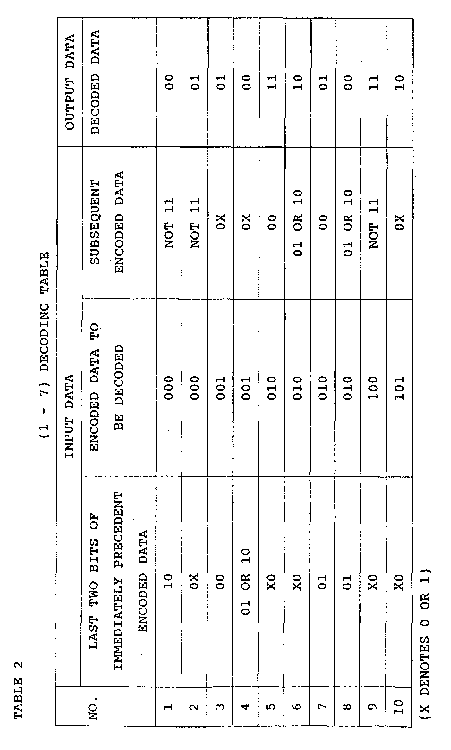
Thus, when the (1-7) encoding scheme is used,
for decoding of encoded data which were encoded, it is
necessary to use not only the encoded data which were
encoded and are a decoding target but also encoded
data which was a decoding target before this encoded
data and subsequent encoded data.
Therefore, in a recording format shown in
Fig. 12, the Sync 1206 containing prefix encoded data
is placed before the data portion 1207 of each sector
so as to decode the top data, while the postamble
(suffix data) 1208 is placed after the data portion
1207 so as to decode the last data.
According to other encoding schemes,
precedent and subsequent data are not needed for
encoding or decoding, a data string having a
predetermined length is uniquely converted into an
encoded data string having a predetermined length with
reference to a predetermined conversion table during
encoding, and an encoded data string having a
predetermined length is uniquely converted into a data
string having a predetermined length with reference to
a predetermined conversion table during decoding.
When such an encoding scheme is used, it is not
necessary to add decoding-purpose data before and
after a data portion unlike described above.
For example, the standard called ASMO
requires to use the NRZI+ method which is one type of
such encoding schemes, to thereby record in divided
data recording areas in a distributed manner.
In a conventional optical memory, a
resolution for reproduction of a signal is determined
almost by the wavelength λ of reproduction light and
the numerical aperture (NA) of an object lens, and a
pit pitch at a detection limit is approximately λ
/(2·NA). However, in these years, since it is not
easy to shorten the wavelength of reproduction light
or increase the numerical aperture of an object lens,
recording mediums, reproduction methods and the like
are improved in an effort to enhance a recording
density of information. With respect to magneto-optic
recording mediums (magneto-optic disks) in particular,
various types of ideas for improvement in recording
density of information have been proposed.
For instance, according to a technique
described in Japanese Patent Application Laid-Open No.
6-290496, magnetic walls coming under a reproduction
light beam are moved one after another, the movements
of the magnetic walls are detected, and a resolution
for reproduction is improved beyond a detection limit
which is determined by the wavelength mentioned above
and the numerical aperture of an object lens (DWDD
scheme). This technique permits to obtain a
particularly favorable reproduction signal, when at
least one layer or all layers of a reproduction layer,
which is a first magnetic layer wherein a magnetic
wall coming under a reproduction light beam moves, a
recording layer which holds a recording signal, and a
switching layer which controls magnetic coupling of
the recording layer and the reproduction layer are
magnetically isolated between information tracks.
In this manner, use of a super resolution
technique such as the DWDD scheme makes it possible to
greatly improve a recording density beyond an optical
limit of λ/(2·NA) in a data area which is for
rewriting data. However, pre-formatted addresses,
control information for tracking and the like are
engraved on an optical disk as concave and convex pits.
A recording density of these pits is under a certain
restriction by a reproduction limit which is dependent
upon the value λ/(2·NA). This leads to problems such
as a deterioration in recording density of an optical
disk, a drop in format efficiency, etc. This will now
be briefly described.
In a conventional optical disk, grooves,
areas between the grooves and the like are used as
recording tracks. Since a signal for tracking control
is obtained from these grooves, there is a restriction
upon an optical resolution which is for a track pitch
to obtain a tracking guide signal from these grooves.
Because of this, it is very difficult to reduce the
track pitch. Where a conventional recording and
reproducing method is used, when a track pitch is
reduced, cross talk from an adjacent track makes
reproduction difficult. Since a track pitch
restricted by cross talk is approximately equal to a
lower limit track pitch which is for obtaining a
tracking signal from a groove, this is not a big
problem in a conventional optical disk. However,
where a reproduction method utilizing DWDD is used,
since a signal is read out during a super resolution
operation by means of movements of a magnetic wall,
cross talk from an adjacent track is reduced. This
permits to record and reproduce with a track density
which is the same or higher than a conventional track
density. Still, it is not possible to improve a track
density because of a track pitch restriction, since a
tracking guide signal is obtained. Among proposed as
means to overcome this problem is an optical disk
using the sample servo method in which adjacent tracks
share wobble pits which are for detection of a
tracking signal and data recording areas are formed as
grooves (Patent Application No. 2000-188200,
PCT/JP01/05232 (which is a patent application which
currently does not stand laid open, and thus, is not
prior art) which is a patent application in which an
inventor is the same as the inventor for this
application). This invention realizes a high density
track pitch.
The restriction upon a recording density in
these pit portions by a reproduction limit which is
dependent on the value λ/(2 · NA) gives rise to the
following problem in terms of a format efficiency.
Considering a sector that an address has 40
bytes and data have 2048 bytes for instance, in the
case of a conventional optical disk (a medium which
does not use a super resolution reproduction method),
a recording density in address portions (areas where
addresses are recorded) is 0.5µm/bit and a recording
density in data portions (areas where data are
recorded) is similarly about 0.5µm/bit.
In this case, a proportion of address data
to the entire data (which is called "address
redundancy") is 0.5 × 40 × 8 / (0.5 × (40 + 2048) ×
8) = 1.91 %.
In the case of an optical disk utilizing a
super resolution reproduction method such as the DWDD
type (or the CAD type, the FAD (Front Aperture
Detection) type or the RAD (Rear Aperture Detection)
type, etc.), while a recording density in an address
portion is 0.5µm/bit, a recording density in a data
portion is about 0.1µm/bit, and hence, the address
redundancy greatly increases to 0.5 × 40 × 8 / ((0.5
× 40 + 0.1 × 2048) × 8) = 8.9 %. The poor format
efficiency is attributed to a format structure of a
conventional optical disk in which one address is
added to one sector.
To overcome the poor format efficiency, such
a structure has been proposed in which a disk is
divided into a plurality of segments and 1-bit
addresses are added to the segments (Japanese Patent
Application Laid-Open No. 11-021885, Japanese Patent
Application Laid-Open No. 11-329265 and Patent
Application No. 2000-339516 (which is a patent
application which currently does not stand laid open,
and thus, is not prior art) which are patent
applications in which an inventor is the same as the
inventor for this application). This eliminates the
one-to-one relationship between addresses and sectors
and accordingly improves a format efficiency.
While a track density needs be improved when
an optical disk is to be made a high-density optical
disk using super resolution reproduction such as DWDD,
a track density beyond an optical resolution of
recording/reproduction light is indispensable. To
realize such a high density, the sample servo method
is essential as a tracking method as described in
relation to the conventional techniques. Where the
sample servo method is used, data in a sector which is
a unit for one rewriting is divided and recorded over
a plurality of segments. An optical disk drive using
a conventional sample servo method, for the purpose of
realizing such division and recording of data, uses a
modulation code which permits to execute modulation
and demodulation regardless of the dependency upon
precedent and subsequent data during recording and
reproduction. Examples are the NRZI modulation method
in the HS standard, the NRZI+ modulation method in the
ASMO standard, the 4-15 modulation method as a
position modulation method, etc. Modulation codes for
these are codes under no run length restriction, or
codes under a very long run length restriction even if
the codes are under restriction.
However, for realization of high-density
recording with a recording/reproduction film using
DWDD, a restriction upon a modulation code attributed
to a reproduction characteristic of a recording film
is created. A DWDD reproduction signal is generated
as a magnetic wall toward the traveling direction of a
light beam. However, as the length of a mark for
recording becomes long, a magnetic wall against the
traveling direction of the light beam, too, moves. A
signal generated in accordance with the movements of
the magnetic walls is called a ghost signal, and
significantly disturbs reproduction of data. Hence,
it is necessary to prevent generation of the ghost
signal. The probability of ghost signal generation
becomes high when the length of a recording mark
reaches a certain level or more. Noting this, it is
desirable that the length of a recording mark, which
is to be recorded in a DWDD recording film, is as
short as possible. To a modulation method for DWDD,
codes under a run length restriction such as 1-7 codes
and 2-7 codes are therefore suitable.
In addition, it is necessary to improve a
linear recording density so as to expand a recording
capacity of a disk. In this case, a limit on a linear
recording density is determined by a limit over the
length of a mark which can be recorded and reproduced
in a DWDD-type recording/reproduction film. This is
because the intensity of a DWDD-type reproduction
signal is not dependent upon an optical resolution of
reproduction light at all. A limit over the length of
a mark which can be recorded and reproduced in a DWDD-type
recording/reproduction film is normally about 0.1
µm. For an improvement in recording density per bit
beyond a limit over the length of a mark which can be
recorded and reproduced as well, it is advantageous to
perform encoding with a run length restriction and
record and reproduce data. Where 1-7 encoding is
executed for instance, a linear recording density is
0.075µm/bit when the minimum length of a mark which
can be recorded is 0.1µm, while where 2-7 encoding is
executed, a linear recording density is 0.067µm/bit
when the mark length is 0.1µm, thereby shortening the
length per bit than the minimum recording mark length
and improving a recording density.
The standard known as ASMO described in
relation to the conventional techniques, too, requires
to divide a sector which is a unit for one rewriting
into a plurality of recording areas for NRZI+ encoding
and recording. During this NRZI+ encoding, a run
length restriction is very long and it is accordingly
difficult to extract a demodulation clock from a
reproduction signal. The ASMO standard therefore uses
an external clock system which generates
recording/reproduction clocks from pits engraved in
advance in a disk. According to a conventional sample
servo method which is generally used, too,
recording/reproduction clocks are generated from pits
engraved in advance in a disk, in a similar fashion.
However, use of a super resolution reproduction method
such as the DWDD scheme in this manner in an effort to
improve a linear recording density leads to the
following problem. It is not possible to perform
super resolution reproduction on clock pits which are
for generation of a reference clock for recording and
reproduction, and therefore, a reproduction limit is
an optical limit of a light beam. The limit is
normally about 0.5µm. On the contrary, a
reproduction limit of a DWDD signal, which is read out
by a super resolution reproduction method, is about
0.1µm which is as five times high as or higher, a
reproduction clock extracted at a reproduction limit
of 0.5µm is insufficient as a clock for reproduction
of a 0.1µm-mark, and thus, the accuracy of clocks
runs short. Hence, it is necessary to extract a
highly accurate reproduction clock from a reproduction
signal for realization of a high density by a super
resolution reproduction method. However, a
conventional optical disk complying with the ASMO
standard or a sample servo scheme is on an assumption
that a reproduction clock is extracted from a clock
pit, and a modulation code uses a modulation method
with which it is not possible to extract a
reproduction clock from a reproduction signal. With
an optical disk system using a conventional sample
servo method or the like which requires to divide a
sector which is a unit for rewriting into a plurality
of recording areas, it is not possible to execute
recording or reproduction at a high density using
super resolution such as that of the DWDD type.
To solve the problem described above, it is
necessary to restrict the minimum recording mark
length and the maximum recording mark length using a
run length limit encoding scheme (which may be the (1-7)
encoding scheme or the like for instance), prevent
ghost over a long mark or a bit reproduction error
over a single mark, and extract a reproduction clock
from an inversion part of a reproduction signal which
is generated as a result of the run length restriction
mentioned above. Further, since it is necessary to
use a sample servo method for the purpose of improving
a track density as described above, it is necessary to
divide a sector which is a unit for rewriting into
segments which are a plurality of areas and record.
However, when the run length limit encoding scheme
described above is used, in order to ensure that
encoding and decoding end within one sector or one
continuous data recording area, it is necessary to
place a prefix data and a suffix data respectively
before and after encoded data to be recorded.
However, when prefix data and a suffix data
are placed respectively before and after encoded data
to be recorded, an effective data recording density of
this recording medium decreases.
Particularly in the event that a recording
track is divided into a number of data recording areas
and data are recorded in such a manner that encoding
and decoding complete within one continuous data
recording area (i.e., in the event that one round of a
disk-shaped recording medium is divided into 1000 or
more data recording areas for instance), an effective
data recording density (a density which is obtained by
converting a data volume of recording data per unit
surface area (channel bit count) into a data volume of
pre-encoding data (input data)) of this recording
medium largely decreases.
Further, the following problem occurs when a
track density is improved by a sample servo method and
a sector which is a unit for rewriting is divided into
segments which are a plurality of areas. In a data
recording area which is in the vicinity of a pit area
which is for detection of a tracking servo signal,
birefringence changes in the data recording area
because of an influence by a pre-pit area, thereby the
envelope of a reproduction signal changes (This
envelope variation will be hereinafter referred to as
a skew distortion.). In a reproducing apparatus, a
skew distortion makes it difficult to binarize a
reproduction signal (i.e., to digitize one bit) an
area near a pre-pit area accordingly becomes unusable
as a data recording area, which serves as a cause of a
deterioration in recording density of the high-density
optical disk. While there is a method of reducing a
skew distortion as much as possible to thereby use a
data recording area which is in the vicinity of a pre-pit
area, in this case, the skew distortion changes
substantially because of a phase difference between P-polarized
light and S-polarized light of an optical
pick-up which executes reproduction, and therefore, in
order to perform reproduction with little skew
distortion, it is necessary to ensure that the phase
difference of the optical pick remains within ±5
degrees. This also serves as a difficulty against
commercialization of a high-density optical disk.
The present invention aims at providing
means which encodes data of a sector which is a unit
for rewriting under a run length restriction, divides
into a plurality of areas and records and accordingly
providing a high-density optical disk. In the case of
a recording and reproducing medium in which recording
and reproduction are executed by a super resolution
reproduction method according to which a data
recording area is beyond an optical resolution, the
present invention brings about an even more
significant effect. The present invention also aims
at a recording medium in which such data are recorded
which makes it easy to accurately binarize a
reproduction signal which has a skew distortion (a
low-frequency waveform distortion) or a differential
signal between two consecutive reproduction signals.
The first invention is directed to a
recording medium, comprising: a pre-pit area
comprising pre-pits; and a plurality of data recording
areas which are divided by the pre-pit area and in
which a data block is recorded which is obtained by
dividing one data stream which is formed by encoded
data which are encoded by an encoding scheme including
a run length limit encoding scheme, wherein in at
least one data recording area, data having a
predetermined value of at lease one bit are further
recorded in front of the data block.
In a conventional recording medium, encoding
and decoding complete within one data recording area.
For example, a conventional recording medium
which uses a run length limit encoding scheme has a
structure that prefix data, a data block and suffix
data are recorded in each data recording area and
encoding and decoding end within each data recording
area.
With prefix data (which may be 001 or the
like for instance) added to and recorded at the top of
each data recording area, it is possible to decode top
data in the data block, and with constant data (which
may be 001 or the like for instance) added to and
recorded at the end of each data recording area, it is
possible to decode last data in the data block
(excluding the added data).
In the conventional recording medium which
uses the run length limit encoding scheme, since
encoding and decoding complete within each one of the
data recording areas, it is necessary that decoding-purpose
data are added to and recorded at the top and
the end of each data recording area, which
deteriorates an effective recording density of the
recording medium as a whole.
The present invention achieves an effect
that it is possible to realize a recording medium
which has a high effective recording density, owing to
continuity between encoded data belonging to each data
recording area (e.g., a data recording area in each
segment) and encoded data belonging to precedent and
subsequent data recording areas.
According to the present invention, addition
of small data makes it possible to divide a data
volume equivalent to one sector (which is a unit of a
chunk of data to be recorded or reproduced, and is one
ECC block in an embodiment) for instance into a
plurality of segments and record.
Hence, unlike the conventional recording
medium, it is not necessary to ensure that a channel
bit count (recordable bit count) of one data recording
area (e.g., a data recording area in each segment) is
the same as a channel bit count of one sector in the
recording medium according to the present invention.
The recording medium according to the present
invention has a higher level of freedom regarding a
format than the conventional recording medium has.
The present invention achieves an effect
that it is possible to realize a recording medium
which has a high recording density.
The present invention achieves an effect
that particularly in a recording medium wherein one
sector is divided into a number of data recording
areas (e.g., a disk-shaped recording medium in which a
recording track whose length is one round is divided
into 1000 or more data recording areas), a recording
medium which has a high effective recording density is
realized.
In an optical disk, for example, in a
portion where a beam spot of a light beam has just
moved from a pre-pit area to a data recording area, a
reproduction signal has a large low-frequency skew
distortion. Hence, it is difficult to binarize a
reproduction signal which was reproduced in the
conventional recording medium.
In the recording medium according to the
present invention, since predetermined additional data
of one bit or more are recorded at the beginning of
each data recording area, it is possible to accurately
binarize a reproduction signal utilizing this, as in a
reproducing apparatus according to an embodiment.
The present invention achieves an effect
that it is possible to realize a recording medium
which permits a reproducing apparatus to accurately
binarize a reproduction signal which contains a skew
distortion (a low-frequency waveform distortion).
The section reading, "plurality of data
recording areas which are divided by the pre-pit area
and in which a data block is recorded which is
obtained by dividing one data stream which is formed
by encoded data which are encoded by an encoding
scheme including a run length limit encoding scheme"
refers to data streams of encoded data which are
encoded by an encoding scheme including a run length
limit encoding scheme, which means that a data stream
in which adjacent pieces of encoded data are
associated with each other is recorded over a
plurality of data recording areas.
Hence, for instance, for the purpose of
decoding encoded data at the top of a data block
recorded in a data recording area, encoded data in a
precedent data block are used, while for the purpose
of decoding encoded data at the end of the data block
recorded in the data recording area, encoded data in a
subsequent data block are used.
Thus, it is not necessary to add and record
decoding-purpose data at the top of each data
recording area (excluding the top data recording area),
or to add and record decoding-purpose data at the end
of each data recording area (excluding the last data
recording area).
Where it is not necessary to use encoded
data in a precedent data block for the purpose of
decoding encoded data at the top of a data block
recorded in a data recording area, this data block and
the precedent data block belong to different data
streams.
The "pre-pit" is a physical concave or
convex portion disposed in a recording medium. An
example is a pre-pit formed on an optical disk
substrate.
The "run length limit encoding scheme"
includes the (1-7) encoding scheme, the (2-7) encoding
scheme and the like. In the event that a recording
density remains the same, such an encoding scheme
generally permits to extend the shortest recording
mark longer than a recording density per bit and
restricts the longest recording mark, thereby allowing
to generate a reference clock for reproduction from a
reproduction signal.
The "recording medium" is any desired medium
(any desired recording element, a medium having any
desired shape) in which digital data are recorded.
Examples are optical disks (including phase-conversion
optical disks and magneto-optical disks), magnetic
cards and the like.
The "data having a predetermined value of at
lease one bit" may be a known value or a value which
is unknown at the time of reproduction. Being "known"
means being known at the time of recording of this
data or reproduction of this data. For instance, this
may be a certain value (0 or 1), data at the last one
bit of an immediately precedent data block (The data
are known at the time of recording of the 1-bit data.),
or data at the last one bit recorded in an immediately
precedent data recording area (The data are known at
the time of reproduction of the 1-bit data.).
The channel bit count of the added data is
any desired figure which is 1 or larger.
The second invention is directed to a
recording medium, comprising: a pre-pit area
comprising pre-pits; and a plurality of data recording
areas which are divided by the pre-pit areas and in
which a data block is recorded which is obtained by
dividing one data stream which is formed by encoded
data which are encoded by an encoding scheme including
a run length limit encoding scheme, wherein in at
least one data recording area, data having the same
value as the last one bit of the encoded data in the
data recording area which is before the data recording
area are further recorded in front of the data block.
The present invention achieves an effect
that it is possible to realize a recording medium
which has a high effective recording density, owing to
continuity between encoded data belonging to each data
recording area and encoded data belonging to precedent
and subsequent data recording areas.
The present invention achieves an effect
that it is possible to realize a recording medium
which has a high effective recording density.
The present invention achieves an effect
that it is possible to realize a recording medium
which permits a reproducing apparatus to accurately
binarize a reproduction signal which contains a skew
distortion (a low-frequency waveform distortion).
In a reproducing apparatus for the recording
medium according to the present invention in which
encoded data encoded by a run length limit encoding
scheme and NRZI-converted for instance are recorded,
as a differential signal between two consecutive
reproduction signals is generated, it is possible to
decode the NRZI-converted encoded data without
influenced by a skew distortion and accordingly
correct an error.
The present invention achieves an effect
that it is possible to realize a recording medium
which can be reproduced using a reproducing apparatus
which has a simple structure.
The "data having the same value as the
encoded data at the last one bit in the data recording
area which is before the data recording area" may have
one bit or a plurality of bits (and the plurality of
bits are all "the same value as the encoded data at
the last one bit").
The third invention is directed to the
recording medium of the first invention, wherein the
data block has the encoded data in a data volume which
is an integer multiple of 2 if a data volume is
converted into a volume of data before being encoded
by a run length limit encoding scheme.
According to the (1-7) encoding scheme for
example, 2-bit input data are converted into three
bits, and encoded data are generated in units of three
bits (the number of channel bits).
Since a data block recorded in the recording
medium according to the present invention has a data
capacity which is an integer multiple of 2 (The
capacity of a data block is expressed as an effective
data size as it is before encoded by a run length
limit encoding scheme.), it is possible to simplify a
control circuit for an encoder which encodes data in
units of three channel bits (which correspond to the
2-bit input data) and a decoder which decodes data in
units of three channel bits (and it is possible to
simplify a processing circuit which is at a joint
between adjacent data blocks in particular).
In addition, it is possible to select the
size of a data block in units of two bits which are
smaller values than units of eight bits or the like
according to a conventional technique.
An optimal channel bit count M of a data
block is expressed by the following formulas, where a
channel bit count of bits which can be physically
recorded in each data recording area is N, a channel
bit count of data other than in data blocks is K, a
unit in which data are processed is L, and a channel
bit count of bits which are not used among the channel
bit count N is P:
M = L × TRUNC ((N - K) / L)
P = N - (M + K) = MOD ((N - K) / L)
The symbol TRUNC () denotes a function for
generating a numerical figure which consists only of
an integer portion of a numerical figure in
parentheses (i.e., for rounding down decimal figures).
The symbol MOD () denotes a function which expresses a
remainder which is obtained by division described in
().
While the maximum value of P is seven bits
in a conventional recording medium wherein the channel
bit count is eight bits for instance, the maximum
value of P, when expressed as the number of channel
bits, is two channel bits in the recording medium
according to the present invention.
The present invention achieves an effect
that it is possible to realize a recording medium
which is less wasted and has a high recording density.
The fourth invention is directed to a
recording apparatus, comprising: an encoding unit
which generates a plurality of data blocks which are
obtained by dividing one data stream which is formed
by encoded data which are obtained by encoding input
data by an encoding scheme including a run length
limit encoding scheme; a data adding unit which adds
data having a predetermined value of at lease one bit
to the top of at least one of the divided data blocks
and generates a data block which contains thus added
data; and a recording unit which records the data
block which contains thus added data in the recording
medium.
The present invention achieves an effect
that it is possible to realize a recording medium
which has a high effective recording density, owing to
continuity between encoded data belonging to each data
recording area and encoded data belonging to precedent
and subsequent data recording areas.
The present invention achieves an effect
that it is possible to realize a recording apparatus
for recording encoded data at a high effective
recording density particularly in a recording medium
wherein one sector is divided into a number of data
recording areas (e.g., a disk-shaped recording medium
in which a recording track whose length is one round
is divided into 1000 or more data recording areas).
In an optical disk for example, since a
reproduction signal has a large low-frequency skew
distortion in a portion where a beam spot of a light
beam has just moved from a pre-pit area to a data
recording area, it is difficult to binarize a
reproduction signal according to a conventional
technique. In the recording medium according to the
present invention, predetermined data are recorded at
the beginning of each data recording area. Hence, it
is possible to accurately binarize a reproduction
signal utilizing this, as in a reproducing apparatus
according to an embodiment for example. The present
invention achieves an effect that it is possible to
realize a recording apparatus for recording data which,
utilizing the added data, is capable of accurately
binarizing a reproduction signal even when the
reproduction signal has a skew distortion (a low-frequency
waveform distortion).
The "data block which contains thus added
data" means data having a predetermined value of at
lease one bit and a data block as they are combined
with each other.
The encoding unit may divide input data
first to thereby generate a plurality of data blocks,
and then encode each data block by an encoding scheme
including a run length limit encoding scheme to
thereby generate a plurality of data blocks of encoded
data.
Alternatively, the encoding unit may first
encode one data stream by an encoding scheme including
a run length limit encoding scheme, and then divide
thus encoded data stream into a plurality of data
blocks.
Alternatively, the encoding unit may first
encode one data stream by a run length limit encoding
scheme, then divide thus encoded data stream into a
plurality of data blocks, and thereafter convert each
data block by other conversion method (such as NRZI
conversion).
The encoding unit according to each
invention includes all these structures described
above but is not limited to these examples above.
This is similar as to the encoding unit according to
the fifth invention and the encoding steps according
to the eleventh invention and the twelfth invention.
The encoding unit and the data adding unit
may constitute blocks which are independent of and
separate from each other, or may have a structure
which is the two integrated with each other in such a
manner that the two can not be separated from each
other.
The fifth invention is directed to a
recording apparatus, comprising: an encoding unit
which generates a plurality of data blocks which are
obtained by dividing one data stream which is formed
by encoded data which are obtained by encoding input
data by an encoding scheme including a run length
limit encoding scheme; a data adding unit which adds
data having the same value as the last one bit of the
encoded data in the data block which is before at
least one of the divided data blocks to the top of at
least one of the divided data blocks and generates a
data block which contains thus added data; and a
recording unit which records the data block which
contains thus added data in the recording medium.
The present invention achieves an effect
that it is possible to realize a recording apparatus
which records data in a recording medium which has a
high effective recording density, owing to continuity
between encoded data belonging to each data recording
area and encoded data belonging to precedent and
subsequent data recording areas.
The present invention achieves an effect
that it is possible to realize a recording apparatus
which records encoded data in a recording medium at a
high effective recording density and with a high error
correcting capability.
The present invention achieves an effect
that it is possible to realize a recording apparatus
which records, in a recording medium data which permit
a reproducing apparatus to accurately binarize a
reproduction signal which contains a skew distortion
(a low-frequency waveform distortion).
The present invention achieves an effect
that it is possible to realize a recording apparatus
which records, in a recording medium, data which can
be reproduced using a reproducing apparatus which has
a simple structure.
The sixth invention is directed to the
recording apparatus of the fourth invention, wherein
the data block has the encoded data in a data volume
which is an integer multiple of 2 if a data volume is
converted into a volume of data before being encoded
by a run length limit encoding scheme.
Since a data block recorded in the recording
medium according to the present invention has a data
capacity which is an integer multiple of 2 (The
capacity of a data block is expressed as an effective
data size as it is before encoded by a run length
limit encoding scheme.), it is possible to simplify a
control circuit for an encoder which encodes data in
units of three channel bits (which correspond to the
2-bit input data) and a decoder which decodes data in
units of three channel bits (and it is possible to
simplify a processing circuit which is at a joint
between adjacent data blocks in particular).
In addition, it is possible to select the
size of a data block in units of two bits which are
smaller values than units of eight bits or the like
according to a conventional technique.
The present invention achieves an effect
that it is possible to realize a recording apparatus
having a simple structure which records, in a
recording medium, data at a high recording density
while avoiding a wasteful use.
The seventh invention is directed to the
recording apparatus of any one of the fourth through
the sixth inventions, wherein the encoding unit or the
data adding unit adds, after the last piece of the
encoded data, data having a predetermined value of n
bits (where n is any desired positive integer).
After recording and reproduction of encoded
data which were encoded by an encoding scheme
including a run length limit encoding scheme using
data which follows data which are an encoding target,
for the purpose of decoding the last data in the data
stream, the subsequent data are further needed.
The recording apparatus according to the
present invention therefore requires to add data
having a certain value (which may be 001 or the like
for instance) after the last encoded data in the data
stream.
The figure n is any desired value. For
instance, data having n bits may be added and recorded
after the last data in the data stream, and any
desired data having k bits (where k is any desired
positive integer) may be further recorded after the
data having n bits.
The eighth invention is directed to a
reproducing apparatus, comprising: a reproducing unit
which reproduces signals recorded in a recording
medium and outputs reproduction signals; a difference
detecting unit which generates differential signals
which represent a difference between two consecutive
ones of the reproduction signals; a binary data
generating unit which generates binary data which are
binarized based on the differential signals; and a
decoding unit which decodes the binary data by a run
length limit encoding scheme.
In an optical disk or the like for example,
since a reproduction signal has a large low-frequency
skew distortion in a portion where a beam spot of a
light beam has just moved from a pre-pit area to a
data recording area, it is difficult to binarize a
reproduction signal according to a conventional
technique.
The reproducing apparatus according to the
present invention subtracts two consecutive
reproduction signals as they are analog signals for
example to thereby generate the differential signal
(which is a differential signal between the analog
signals), or converts two consecutive reproduction
signals into digital signals having a plurality of
bits (10-bit data for example) and then generates a
differential signal between the two consecutive
digital signals having a plurality of bits (which is a
differential signal between the plurality of bits).
The differential signal is thereafter binarized.
Since the differential signal between the
analog signals or the differential signal between the
plurality of bits is generated first, even when the
reproduction signals contain a skew distortion (a low-frequency
waveform distortion), the skew is cancelled
and fails to be contained in the differential signal.
The present invention achieves an effect
that it is possible to realize a reproducing apparatus
which accurately binarizes a reproduction signal
without influenced by a skew.
In a conventional reproducing apparatus
which reproduces NRZI-converted encoded data for
instance, since reproduction signals are binarized and
a differential signal between thus binarized two
consecutive reproduction signals is generated to
thereby execute decoding, a skew is influential.
The present invention achieves an effect
that it is possible to realize a reproducing apparatus
which accurately binarizes a reproduction signal
without influenced by a skew and simultaneously
decodes (inverse conversion) an NRZI-converted
reproduction signal.
The ninth invention is directed to a
reproducing apparatus, comprising: a reproducing unit
which reproduces, from a recording medium, encoded
data which are encoded by an encoding scheme including
a run length limit encoding scheme and recorded as
they are divided into a plurality of data blocks; and
a decoding unit which, using the encoded data of the
data block and the encoded data of the next data block,
decodes the encoded data of the data block or the next
data block.
The present invention achieves an effect
that it is possible to realize a reproducing apparatus
which reproduces and decodes encoded data which are
recorded in a recording medium at a high effective
recording density, owing to continuity between encoded
data belonging to each data recording area and encoded
data belonging to precedent and subsequent data
recording areas.
A conventional reproducing apparatus which
uses a run length limit encoding scheme for instance
is capable of only reproducing a signal from a
recording medium in which recorded within each data
recording area is such a data block which permits
decoding to finish only within each data block.
The present invention achieves an effect
that it is possible to realize a reproducing apparatus
particularly for a recording medium in which data
covering one sector are divided over a number of data
recording areas (For example, recording tracks (each
having a length equivalent to one round within a disk)
in a disk-shaped recording medium are each divided
into 1000 or more data recording areas.) and recorded
at a high effective recording density.
The tenth invention is directed to a
reproducing apparatus, comprising: a reproducing unit
which reproduces and outputs, from each one of a
plurality of data recording areas of a recording
medium, reproduction signals of data blocks and
predetermined data further recorded before the data
blocks; a binarizing unit which binarizes the
reproduction signals and outputs binary signals; and a
decoding unit which combines, in the order of
reproduction from the data recording areas, the binary
signals of a plurality of the data blocks with each
other except for the predetermined data of other data
blocks than at least the top data block, and decodes
the binary signals thus combined by a run length limit
encoding scheme.
The present invention achieves an effect
that it is possible to realize a reproducing apparatus
which reproduces and decodes encoded data which are
recorded in a recording medium at a high effective
recording density, as a data stream encoded by a run
length limit encoding scheme is divided into a
plurality of data blocks and each data block is
recorded in each data recording area. As a
reproduction signal is binarized using predetermined
data as in an embodiment for instance, it is possible
to binarize the reproduction signal without influenced
by a skew.
The predetermined data is any desired data
having one bit or more.
The decoder unit may decode from a binarized
signal, excluding the predetermined data other than in
at least the data block located at the top, or the
binarizing unit may not binarize these predetermined
data (The embodiments are the latter.).
The eleventh invention is directed to a
reproducing apparatus, comprising: a reproducing unit
which reproduces a data stream of encoded data which
are encoded by an encoding scheme including a run
length limit encoding scheme from a recording medium;
a counter which counts the number of encoded data of
the data stream, the number of encoding processes or
the number of decoded data; a last encoded data
detecting unit which detects a last encoded data of
the data stream based on the value of the counter; and
a decoding unit which, when the last encoded data
detecting unit detects that a decoding-target encoded
data is the last encoded data, decodes the decoding-target
encoded data using at least the decoding-target
encoded data and data having a constant value.
In conventional reproducing apparatus which
uses an encoding scheme including a run length limit
encoding scheme which requires to use subsequent
encoded data at the time of decoding, for the purpose
of decoding the last encoded data in a data stream, it
is necessary to reproduce from a recording medium
subsequent encoded data which follows the last encoded
data.
The reproducing apparatus according to the
present invention decodes the last encoded data using
data having a certain value (which are typically data
held in the decoder unit) held in the reproducing
apparatus.
The present invention achieves an effect
that it is possible to realize a reproducing apparatus
which decodes a reproduction signal reproduced from a
recording medium in which data for decoding the last
encoded data are not recorded.
The counter and the last encoded data
detector unit may directly count the number of encoded
data or the like, or indirectly count the number of
encoded data. This virtually includes counting of the
number of encoded data of the data stream, the number
of encoding processes or the number of decoded data.
This is counting of channel bits one bit or
three bits each, for instance. This is to count the
number of encoding conversions for example or to count
the number of decoded data (the number of clocks).
Since 3-bit encoded data are generated
through one encoding conversion, it is possible to
calculate the number of encoded data based on counting
of the number of encoding conversions by the formula
below:
The number of encoded data = 3 × the number
of encoding conversions
In a similar fashion, with respect to
encoded data which were encoded by the (1-7) encoding
scheme for example, since 2-bit decoded data are
generated through decoding of 3-bit encoded data, it
is possible to calculate the number of encoded data
based on counting of the number of decoded data by the
formula below:
The number of encoded data = 1.5 × the
number of decoded data
An example will now be considered that 900
reproduction clocks (clocks for encoded data) are
generated per segment (including a pre-pit area),
encoded data are reproduced with reference to the 111-st
through the 890-th reproduction clocks (The first
through 110-th and the 891-st through the 900-th
clocks are for areas in which data are not recorded
(pre-pit areas).), and the 410-th clock is for the
last encoded data (Data are recorded from the 111-st
through the 410-th clocks.).
The counter is reset at the 110-th
reproduction clock (i.e., becomes zero), and when the
value in the counter reaches 300 (the 410-th clock),
the last encoded data detector unit detects the last
encoded data.
Alternatively, the counter is reset at the
0-th reproduction clock (= the 900th clock) (i.e.,
becomes zero), and when the value in the counter
reaches 410 (the 410-th clock), the last encoded data
detector unit detects the last encoded data (Since it
is known that there is not encoded data from the first
through 110-th clocks, the number of encoded data of a
data stream is virtually counted.).
By a method according to the example above
or the like, the last encoded data is detected.
The twelfth invention is directed to a
recording method, comprising: an encoding step of
generating a plurality of data blocks which are
obtained by dividing one data stream which is formed
by encoded data which are obtained by encoding input
data by an encoding scheme including a run length
limit encoding scheme; a data adding step of adding
data having a predetermined value of at lease one bit
to the top of at least one of the divided data blocks
and generating a data block which contains thus added
data; and a recording step of recording the data block
which contains thus added data in the recording medium.
The present invention achieves an effect
that it is possible to realize a recording method of
recording encoded data in a recording medium at a high
effective recording density, owing to continuity
between encoded data belonging to each data recording
area and encoded data belonging to precedent and
subsequent data recording areas.
The present invention achieves an effect
that it is possible to realize a recording method of
recording encoded data at a high effective recording
density and under a run length limit restriction
particularly in a recording medium in which one sector
is divided into a number of data recording areas (e.g.,
a disk-shaped recording medium in which a recording
track whose length is one round is divided into 1000
or more data recording areas).
The recording method according to the
present invention requires to record predetermined
data at the beginning of each data recording area.
Hence, using the reproducing method according to the
present invention, it is possible to accurately
binarize a reproduction signal utilizing this as in
the reproducing method according to an embodiment for
example.
The present invention achieves an effect
that it is possible to realize a recording method of
recording data which permits accurate binarization of
a reproduction signal, owing to use of the added data
even when the reproduction signals contain a skew
distortion (a low-frequency waveform distortion).
The thirteenth invention is directed to a
recording method, comprising: an encoding step of
generating a plurality of data blocks which are
obtained by dividing one data stream which is formed
by encoded data which are obtained by encoding input
data by an encoding scheme including a run length
limit encoding scheme; a data adding step of adding
data having the same value as the last one bit of the
encoded data in the data block which is before at
least one of the divided data blocks to the top of at
least one of the divided data blocks and generates a
data block which contains thus added data; and a
recording step of recording the data block which
contains thus added data in the recording medium.
The present invention achieves an effect
that it is possible to realize a recording method of
recording data in a recording medium at a high
effective recording density, owing to continuity
between encoded data belonging to each data recording
area and encoded data belonging to precedent and
subsequent data recording areas.
The present invention achieves an effect
that it is possible to realize a recording method of
recording encoded data in a recording medium at a high
effective recording density and with a high error
correcting capability.
The present invention achieves an effect
that it is possible to realize a recording method of
recording, in a recording medium data which permit a
reproducing apparatus to accurately binarize a
reproduction signal which contains a skew distortion
(a low-frequency waveform distortion).
The fourteenth invention is directed to the
recording method of the twelfth invention, wherein the
data block has the encoded data in a data volume which
is an integer multiple of 2 if a data volume is
converted into a volume of data before being encoded
by a run length limit encoding scheme.
Since a data block recorded in a recording
medium by the recording method according to the
present invention has a data capacity which is an
integer multiple of 2 (The capacity of a data block is
expressed as an effective data size as it is before
encoded by a run length limit encoding scheme.), it is
possible to simplify the encoding process of encoding
data in units of three channel bits (which correspond
to the 2-bit input data) and the decoding process of
decoding data in units of three channel bits (and it
is possible to simplify processing over a joint
between adjacent data blocks in particular).
In addition, it is possible to select the
size of a data block in units of two bits which are
smaller values than units of eight bits or the like
according to a conventional technique.
The present invention achieves an effect
that it is possible to realize an inexpensive
recording method of recording, in a recording medium,
data at a high recording density while avoiding a
wasteful use.
The fifteenth invention is directed to the
recording method of any one of the twelfth through the
fourteenth inventions, wherein at the encoding step or
the data adding step, data having a predetermined
value of n bits (where n is any desired positive
integer) are added after the last piece of the encoded
data.
The recording method according to the
present invention requires to add data having a
constant value (which may be 1 for instance) after the
last encoded data in the data stream. Therefore, it
is possible to decode the last encoded data, using a
reproducing apparatus.
The sixteenth invention is directed to a
reproduction method, comprising: a reproducing step of
reproducing signals recorded in a recording medium and
outputting reproduction signals; a difference
detecting step of generating differential signals
which represent a difference between two consecutive
ones of the reproduction signals; a binary data
generating step of generating binary data which are
binarized based on the differential signals; and a
decoding step of decoding the binary data by a run
length limit encoding scheme.
The present invention achieves an effect
that it is possible to realize a reproduction method
of accurately binarizing a reproduction signal without
influenced by a skew.
The seventeenth invention is directed to a
reproduction method, comprising: a reproducing step of
reproducing, from a recording medium, encoded data
which are encoded by an encoding scheme including a
run length limit encoding scheme and recorded as they
are divided into a plurality of data blocks; and a
decoding step of, using the encoded data of the data
block and the encoded data of the next data block,
decoding the encoded data of the data block or the
next encoded data.
The present invention achieves an effect
that it is possible to realize a reproduction method
of reproducing and decoding encoded data which are
recorded in a recording medium at a high effective
recording density, owing to continuity between encoded
data belonging to each data recording area and encoded
data belonging to precedent and subsequent data
recording areas.
The present invention achieves an effect
that it is possible to realize a reproduction method
particularly for a recording medium in which data
covering one sector are divided over a number of data
recording areas (For example, recording tracks (each
having a length equivalent to one round within a disk)
in a disk-shaped recording medium are each divided
into 1000 or more data recording areas.) and recorded
at a high effective recording density.
The eighteenth invention is directed to a
reproduction method, comprising: a reproducing step of
reproducing and outputting, from each one of a
plurality of data recording areas of a recording
medium, reproduction signals of data blocks and
predetermined data further recorded before the data
blocks; a binarizing step of binarizing the
reproduction signals and outputting binary signals;
and a decoding step of combining, in the order of
reproduction from the data recording areas, the binary
signals of a plurality of the data blocks with each
other except for the predetermined data of other data
blocks than at least the top data block, and decoding
the binary signals thus combined by a run length limit
encoding scheme.
The present invention achieves an effect
that it is possible to realize a reproduction method
of reproducing and decoding encoded data which are
recorded in a recording medium at a high effective
recording density, as a data stream encoded by a run
length limit encoding scheme is divided into a
plurality of data blocks and each data block is
recorded in each data recording area.
As a reproduction signal is binarized using
predetermined data as in an embodiment for instance,
it is possible to binarize the reproduction signal
without influenced by a skew.
The nineteenth invention is directed to a
reproduction method, comprising: a reproducing step of
reproducing, from a recording medium, a data stream of
encoded data which are encoded by an encoding scheme
including a run length limit encoding scheme; a
counting step of counting the number of encoded data
of the data stream, the number of encoding processes
or the number of decoded data; a last encoded data
detecting step of detecting a last encoded data of the
data stream based on the value of the counter; and a
decoding step of, when the last encoded data detecting
unit detects that a decoding-target encoded data is
the last encoded data, decoding the decoding-target
encoded data while using at least the decoding-target
encoded data and data having a constant value.
The present invention achieves an effect
that it is possible to realize a reproduction method
of decoding a reproduction signal reproduced from a
recording medium in which data for decoding the last
encoded data are not recorded.
While the novel features of the present
invention are those described particularly in the
attached claims, the present invention, both in terms
of structure and content, will be more apparently
understood and evaluated, together with other objects
and features, when taken in conjunction with the
following detailed description which would be
understood with reference to the associated drawings.
It is to be noted that some or all drawings
show an overview for the purpose of illustration and
do not necessarily depict relative sizes, positions
and the like of elements.
With reference to the associated drawings,
embodiments will now be described which are the best
mode for implementing the present invention.
An embodiment 1 of the present invention
will now be described.
Part (a) of Fig. 1 shows a general overall
structure of a magneto-optical disk 100 according to
the embodiment 1 of the present invention.
In part (a) of Fig. 1, denoted at is an
optical disk substrate, denoted at 102 is a DWDD
recording/reproduction film which permits super
resolution reproduction, denoted at 103 is a first
recording track, denoted at 104 is a second recording
track which is adjacent to the first recording track,
denoted at 105 are segments obtained by dividing the
first recording track 103 and the second recording
track 104 into 1280 pieces, denoted at 106 and 113 are
pre-pit areas (pre-formatted areas).
The pre-formatted areas 106 and 113 comprise
clock pits, servo pits for tracking, and address pits
which are indicative of position information regarding
a disk.
As shown in the drawing, the first recording
track 103 and the second recording track 104 are
spiral areas which start and end at the pre-pit areas:
When the spiral recording tracks are traced from an
inner round toward an outer round of the magneto-optical
disk, the second recording track 104 ends at
the pre-pit area 113, and the first recording track
103 starts where the second recording track 104 ends
(the pre-pit area 113).
In part (a) of Fig. 1, while the magneto-optical
disk is a disk whose diameter is about 50 mm,
a track pitch of the first recording track 103 and the
second recording track 104 is about 0.6µm. In part
(a) of Fig. 1 which aims at describing a format
structure of the magneto-optical disk, as compared to
the size of the magneto-optical disk as a whole, the
first recording track 103 and the second recording
track 104 which are adjacent to each other are shown
as they are extremely enlarged.
Part (b) of Fig. 1 is a schematic enlarged
view of one segment 105.
In part (b) of Fig. 1, denoted at 105 is a
segment (which is comprised of one recording track and
one pre-pit area), denoted at 106 is a pre-pit area
(pre-formatted area), and a ditch portion (groove
portion) 111 having a length 107 is a recording track
(data recording area) for recording data.
The pre-pit area 106 comprises clock pits
115, wobble pits 108 and 109, and address pits 110 in
which address information is distributed one bit each
at the beginning of a segment.
Inter-ditch portions (land portions) 114
having a length 107 magnetically block adjacent ditch
portions from each other.
The clock pits 115 are located at the top of
the respective segments. With a frequency-divided
signal obtained by dividing an output signal from a
voltage controlled oscillator synchronized to a
detection signal indicative of the clock pits of the
respective segments, it is possible to use the output
signal from the voltage controlled oscillator as a
synchronization clock for data encoding during
recording. The output signal from the voltage
controlled oscillator is used also as a
synchronization clock for a window clock generation
circuit which detects the wobble pits 108 and 109 and
the address pits 110.
The paired wobble pits 108 and 109 are
located half a track displaced in opposite directions
to each other with respect to center lines of the
recording tracks 103 and 104, and the polarities of
the paired wobble pits 108 and 109 are inverted every
round of the recording tracks 103 and 104.
A tracking error signal is generated based
on a difference in terms of the amount of reflected
light from said wobble pits 108 and 109, and tracking
control of a light beam is performed such that the
amounts of reflected light from the wobble pits 108
and 109 will be equal to each other.
Whether there are the address pits 110
provides one bit of information per segment. 80
pieces of the address pits 110 gathered together make
one piece of position information. The position
information expresses a segment position along a track
direction and the radius direction on the magneto-optical
disk. As for a method of recording such
address information, applications regarding a
distributed address format (Japanese Patent
Application Laid-Open No. 11-021885 and Japanese
Patent Application Laid-Open No. 11-329265) describe
the details.
A master optical disk is processed by
etching with a laser beam, thereby generating a clock
pit, two wobble pits, an address pit and a ditch
portion on the master disk.
Transferred from a stamper at the time of
injection, the clock pit 115, the wobble pits 108 and
109, the address pit 110 and the ditch portion 111 are
formed on the optical disk substrate 101. On the
optical disk substrate 101 of polycarbonate molded by
the injection method, the DWDD recording/reproduction
film 102 is formed together with a protection layer by
a sputtering method.
The magneto-optical disk according to the
present invention formed in this manner comprises the
spiral-shaped recording tracks 103 and 104 and the
like, the recording tracks 103 and 104 and the like
are divided each into 1280 pieces of the segments 105
by the pre-pit areas 106 which are disposed radially
(aligned along the radius direction of the magneto-optical
disk).
The pre-pit areas 106 in the respective
segments are aligned along the radius direction of the
magneto-optical disk. Hence, when expressed in
angular coordinates whose origin is the center of the
magneto-optical disk, the pre-pit areas are located at
every 360 degrees / 1280 pieces = 0.28125 degree on
the magneto-optical disk, regardless of distances of
positions at which the recording tracks are located
from the origin.
One segment 105 comprises one pre-pit area
106 and the ditch portion 111 which is one data
recording area.
The magneto-optical disk according to the
present invention comprises the wobble pits 108 and
109 for tracking in the pre-pit areas 106, and either
the wobble pits 108 or 109 are shared by adjacent
recording tracks.
Based on such a structure, the first
recording track 103 and the second recording track 104
are provided alternately each other which have
different tracking polarities (with the wobble pits
108 and 109 respectively located one on the right-hand
side and the other on the left-hand side to extension
of the recording track in one case, and with the
wobble pits 108 and 109 respective located one on the
left-hand side and the other on the right-hand side in
the opposite manner in other case).
In the data recording areas (the ditch
portions 111), encoded data are continuously recorded.
As described later, this embodiment requires
to encode an ECC block by the (1-7) encoding scheme
and then execute NRZI-conversion. Encoded data having
run length thus generated of 2T through 8T (where T
denotes a time length of a channel bit equivalent to
one bit) are recorded. However, in some cases, the
run length may become 1T (The same values do not
appear in a row.) as for the top one bit and the last
one bit. A reproduction signal with a run length of
1T has a higher basic frequency than an ordinary
reproduction signal whose run length is 2T through 8T,
and therefore, may make reproduction difficult.
When the data described above are recorded
in the pre-write portion 116 or the post-write portion
117, the run lengths in the top one bit and the last
one bit practically become 2T or longer, which in turn
makes it possible to correctly reproduce the top one
bit and the last one bit without fail.
Part (c) of Fig. 1 schematically shows the
waveform of an analog reproduction signal 118 for data
which are recorded in the segment 105.
As shown in the drawing, the analog
reproduction signal as it is immediately after an
optical pick up moves to the ditch portion 111 from
the pre-pit area 106 contains a skew (a low-frequency
envelope distortion) denoted at 119. Because of this,
even when the analog reproduction signal is binarized
with reference to a constant level 120 which serves as
a threshold value, it is not possible to correctly
binarize in the skew portion 119.
Further, as schematically shown in Fig. 2,
the magneto-optical disk according to the embodiment 1
is divided into a plurality of data zones 201 in
accordance with a distance along the radius direction.
A constant volume of data are recorded in
the respective segments within the same data zone, and
as the data zone is closer to the outer round, more
data are recorded in the respective segments. Hence,
in a recording/reproduction mode at a constant
recording data rate for instance, the magneto-optical
disk rotates at a constant angular velocity within the
same data zone, but within different data zones, the
magneto-optical disk rotates at a slower angular
velocity as the data zone is closer to the outer round.
Fig. 3 is a drawing which shows a structure
of a recording apparatus for the optical disk
according to the embodiment 1.
In the drawing, denoted at 100 is the
magneto-optical disk, denoted at 301 is a magnetic
head, and denoted at 302 is the optical pick-up. The
magnetic head 301 and the optical pick-up 302 move on
the magneto-optical disk 100, while remaining faced
with each other with the magneto-optical disk 100
positioned between the two.
The magneto-optical disk 100 according to
this embodiment records and reproduces data by means
of laser-pulsed magnetic field modulation. At the
time of recording, in a condition that the magnetic
head 301 is developing a magnetic field, the optical
pick-up 302 irradiates laser light upon the recording
film, whereby data are recorded in the magneto-optical
disk. At the time of reproduction, with laser light
irradiated upon the recording film, reflected light
which is polarized along the direction of the magnetic
field during recording is detected, whereby signals
recorded in the magneto-optical disk are reproduced.
The recording apparatus for the optical disk
(a recording unit of an optical disk drive) comprises
the magnetic head 301, the optical pick-up 302, an ECC
encoder 308 (ECC stands for Error Correction Code), a
RAM 307, an encoding unit 306, a data adding part 305,
a magnetic head driving part 304, a laser driving part
303, a write/read control part 309 and a
synchronization clock generating part 310.
The synchronization clock generating part
310 generates synchronization clocks which serve as a
reference during recording, from the clock pits 115
which are formed on the magneto-optical disk 100.
The synchronization clock generating part
310 sends synchronization clocks to the data adding
part 305, the write/read control part 309, the
encoding unit 306, the ECC encoder, the RAM 307, etc.
The write/read control part 309 receives the
synchronization clocks, and controls operations of the
ECC encoder 308, the RAM 307, the encoding unit 306,
the data adding part 305 and the laser driving part
303.
Input data (recording data) are fed to the
ECC encoder 308.
After storing the input data in the RAM 307,
the ECC encoder 308 generates an ECC block to which
redundancy data are added and in which data are
interleaved.
An ECC block is an aggregation of 38336-B
data (including 32-kB data and the redundancy data)
generated through one ECC encoding process, and is the
minimum write/read unit.
A (1-7) encoder and an NRZI convertor are
reset for every ECC block, and (1-7) encoding and NRZI
conversion are newly started at the top of the ECC
blocks.
After (1-7) encoded and NRZI-converted, a
new ECC block is recorded (excluding prefix data and
the like) starting at the top of a new segment in the
recording medium.
The ECC encoder 308 divides and outputs,
approximately for each data block, thus generated ECC
block.
One data block is converted into encoded
data by the encoding unit 306, added to with necessary
data by the data adding part, and recorded in one data
recording area.
The encoding unit 306 comprises a (1-7)
encoder 312 and an NRZI convertor 311.
The (1-7) encoder 312 receives the ECC block
outputted from the ECC encoder 308, encodes the ECC
block by the (1-7) encoding scheme in synchronization
to an encoding clock generated by the synchronization
clock generating part 310 (Through conversion, a run
length of the ECC block is restricted. That is, the
number of zeroes appearing in a row is restricted to
the range of 1 through 7.), and outputs encoded data.
As shown in Table 1, encoded data encoded by
the (1-7) encoding scheme has a data volume which is
1.5 times as large as that of original data, and
therefore, encoded data resulting from one ECC block
have a size of about 58 kB (channel bit count).
The write/read control part 309 counts the
encoding clocks and identifies the last bit of a data
block.
When the write/read control part 309
identifies the last bit of a data block, the (1-7)
encoder 312 stops operating after the last bit is
outputted, and starts operating again at the timing of
starting transmission of the next data block.
As described later, before encoding data
representing one ECC block, the encoding unit 306 is
set with an initial value (prefix data), and starts
encoding at the initial value.
Before outputting an encoded data block
located at the top (a top portion of one ECC block),
the encoding unit 306 outputs 3-bit prefix encoded
data 407 (encoded data having the initial value).
Values of the 3-bit prefix encoded data 407 are shown
under the INPUT DATA section, 2, "ENCODED DATA OF
PREFIX INPUT DATA" section in Table 3 (001 or 010 in
accordance with a 2-bit value which is at the top of
one ECC block).
The purpose of generating the 3-bit prefix
encoded data and recording in the recording medium is
to correctly encode the first three bits of the
encoded data of one ECC block (The last two bits of
precedent encoded data are used. In the embodiment 1,
01 or 10 is used.).
In a similar fashion, the encoding unit 306
additionally receives 2p pieces (where p is a positive
integer) of suffix data (which are data representing
successive zeroes in the embodiment) after the last
data of one ECC block, and after encoding the last
data block (the last portion of the ECC block),
further encodes the suffix data and outputs suffix
encoded data 408.
The ECC encoder 308 stores the suffix data
in the RAM 307, and after outputting the last data
block, outputs the suffix data following this.
The encoded data outputted from the (1-7)
encoder 312 are transmitted to the NRZI convertor 311.
The NRZI convertor 311 is reset before
receiving the added data block to one ECC block, and
outputs output data 0.
The NRZI convertor 311 receives the encoded
data outputted from the (1-7) encoder 312, and outputs
NRZI-converted encoded data.
NRZI conversion is an encoding scheme which
requires to invert the level of a (0 → 1 or 1 → 1)
signal only when the next bit is 1.
Ones do not appear in a row in the encoded
data encoded by the (1-7) encoding scheme according to
this embodiment, and during operations of the NRZI
convertor, an (0 → 1) output is inverted at a rising
edge of the data.
In other words, the NRZI convertor 311
starts at an initial value 0 and is inverted from 1 to
0 or from 0 to 1 every time the input data change from
0 to 1.
Fig. 5 is a timing chart which shows
operations of the NRZI convertor 311.
Numerical values of the input data to the
NRZI convertor 311 are shown in part (a) of Fig. 5,
and the waveform is shown in part (b) of Fig. 5. In
accordance with the input data shown in parts (a) and
(b) of Figs. 5, the NRZI convertor 311 outputs output
data as that shown in part (c) of Fig. 5.
While a bit rate and an information volume
of the NRZI-converted encoded data remain the same as
those of the original encoded data (In NRZI-converted
encoded data, information exists at a point of level
change), the basic frequency is low. Since the basic
frequency of the data becomes low, it is possible to
record data in the recording medium at a high
recording density.
The data adding part 305 receives the prefix
encoded data 407 outputted from the NRZI convertor 311
(the encoding unit 306), the data blocks of the
encoded data and the suffix encoded data 408, adds
constant data 406 (data having five bits in total) and
data 405 (data which have four bits in total and are
denoted at the reference symbol 409) which have the
same value as the encoded data at the last one bit of
the precedent data block, both of which will be
described later, respectively before the prefix
encoded data 407 and the suffix encoded data 408, and
outputs thus added data block.
In a similar manner, the data 405 (data
which have four bits in total and are denoted at the
reference symbol 409) which have the same value as the
encoded data in the last one bit are added after the
last encoded data of each data block, and the data are
outputted.
The data adding part 305 is formed by one D
flip-flop for instance. Before starting outputting of
the encoded data of the ECC block, the D flip-flop is
reset and outputs zero.
Before loading the prefix encoded data 407
and outputting, the data adding part 305 outputs zero
(the constant data 406) for a 5-clock period. A 4-clock
period corresponds to the pre-write portion 116.
Data recorded during the last 1-clock period are top
effective data which are recorded in the data
recording area.
In addition, after the encoded data of each
data block or the suffix encoded data 408 are loaded
and outputted, the data 405 having the same value as
the encoded data at the last one bit of each data
block or the suffix encoded data 408 are held.
Following the last encoded data of each data block,
the data 405 are outputted for a 4-clock period (The
4-clock period corresponds to the post-write portion
117. These four bits are illustrated as they are
included in the symbol 408.).
During a period in which the optical pick-up
moves over the pre-pit area, the data adding part 305
holds the data 405 (excluding after outputting the
suffix encoded data 408).
Before the next data block is loaded and
outputted, the data 405 are outputted further for a 5-clock
period. A 4-clock period corresponds to the
pre-write portion 116. Data recorded during the last
1-clock period are top effective data which are
recorded in the data recording area.
The function of the data adding part 305
described above is easily executed by means of clock
control.
In other embodiments, the data adding part
305 is integrated with the NRZI convertor 311.
The magnetic head driving part 304 receives
the added data block from the data adding part 305,
and energizes the magnetic head 301 with a current
which is in accordance with each piece of the encoded
data in the added data block. The magnetic head 301
develops a magnetic field which is in accordance with
this current.
When the magnetic head driving part 304
energizes the magnetic head 301 with a current, the
write/read control part 309 transmits to the laser
driving part 303 pulses having the same pitches
(constant pitches) as bit pitches of each piece of the
encoded data (channel bits). The laser driving part
303 outputs laser light having said constant pitches,
and the laser light heats up the recording film of the
magneto-optical disk via the optical pick-up 302. As
a result, the encoded data (channel bits) are recorded
in the recording film.
In this manner, the data blocks containing
the added data are recorded in the data recording
areas in the respective segments of the magneto-optical
disk 100.
In the magneto-optical disk according to the
embodiment 1, a channel bit count recordable in each
data recording area is different between the data
zones, and the recording capacity increases as the
data zone is closer to the outer round.
It is possible to record data having 468
bits (when expressed as the number of data before
encoding by the (1-7) encoding scheme) in one segment
within the inner-most data zone and record data having
986 bits in one segment within the outer-most data
zone.
It is possible to record one ECC block, with
the ECC block divided into the number of segments
which is calculated as TRUNC (8 · Q / N) + 1, where a
channel bit count of one ECC block is Q bytes and a
channel bit count recordable in the data recording
area of each segment is N bits (TRUNC denotes a
function for outputting a value which is obtained by
rounding down decimal figures of a calculated value in
the parentheses.).
According to rough calculation, in the
inner-most data zone, one ECC block is recorded over
656 segments, according to TRUNC (8 bits × (32 kB +
5088 + 480) / 468) + 1 = 656. In the outer-most data
zone, one ECC block is recorded over 312 segments,
according to TRUNC (8 bits × (32 kB + 5088 + 480) /
986) + 1 = 312 (5088 bytes and 480 bytes are
redundancy data of the ECC block.).
Fig. 4 shows a method according to which the
ECC encoder 308 reads out an ECC block written in the
RAM 307, the encoding unit 306 encodes the ECC block
and the data adding part 305 adds predetermined data
to a data block.
The ECC encoder 308 writes one ECC block and
suffix data (The data are data of repeated 00.
Encoded by the (1-7) encoder 312, the data become the
3-bit suffix encoded data 408 (which are data of
repeated 001) having 2p bits (where p is a positive
integer) in the RAM 307.
The ECC encoder 308 reads a data block
(which will become the first data block 402 after
encoded) of data recorded in the top segment within
one ECC block 401, from the RAM 307.
Before starting encoding of an ECC block,
the (1-7) encoder 312 is set to an initial value as
described later.
The (1-7) encoder 312 encodes the initial
value to thereby generate and output the 3-bit prefix
encoded data 407, and receives the first data block to
be inputted, encodes the first data block to thereby
generate and output the first data block 402 which is
formed by the encoded data.
The data adding part 305 receives the 3-bit
prefix encoded data 407 and the first data block 402,
adds the constant data 406 having five bits (The data
may be two bits or more. The data are all zero in the
embodiment 1.) to the top of these encoded data, adds
the 4-bit data 409 which have the same value as the
data 405 in the last one bit of the data block 402
after the data block 402, and outputs the first data
block which contains the added data.
The first four bits of the 5-bit constant
data 406 are recorded in the pre-write portion 116.
The added first data block, which is formed by the
last one bit of the 5-bit constant data 406, the 3-bit
prefix encoded data 407 and the first data block 402,
is recorded in the data recording area within the
first segment 111.
Although not being effective encoded data,
these first four bits recorded in the pre-write
portion 116 prevent the run length of the 1-bit
constant data 406 from becoming 1T and accordingly
guarantee the run length of 2T or longer.
Further, the data adding part 305 stores the
value of the last piece of the encoded data 405 in the
first data block 402.
Even after outputting the first added data
block (including the last piece of the encoded data
405), the data adding part 305 keeps outputting the
last piece of the encoded data 405 of the first data
block 402 further for a 4-bit period (409. Only one
bit or more needs be contained.). The 4-bit data 409
are recorded in the post-write portion 117.
Although not being effective encoded data,
these four bits recorded in the post-write portion 117
prevent the run length of the last piece of the
encoded data 405 of the first data block 402 from
becoming 1T and accordingly guarantee the run length
of 2T or longer.
The formula below holds satisfied in the
embodiment 1.
One channel bit (constant data 406) + three
channel bits (prefix encoded data 407) + the channel
bit count of the first data block 402 = the channel
bit count of the data area within one segment
In an optical disk drive which needs a
constant period of time until a laser light output
stabilizes after the start of recording, the data
adding part 305 outputs a header portion having a
constant data length (a 32-bit data string having the
value 0 for instance) and a Sync portion having a
constant data length (a synchronizing portion), the 3-bit
prefix encoded data 407. These data are recorded
in the first segment 111.
The data length of the header portion is
determined so that a recording time for the header
portion will be longer than a period of time needed
for a laser light output to stabilize after the start
of recording. This makes it possible to guarantee the
reliability of a reproduction signal for data
following the header portion.
The Sync portion is a known signal for byte
synchronization of a data string which follows the
header portion. This is 8-bit data which may be
11110000 for example.
Next, the ECC encoder 308 reads a data block
(which will become the second data block 403 after
encoded) of data recorded in the second segment within
one ECC block 401, from the RAM 307.
The (1-7) encoder 312 encodes the data block
of the data which are to be recorded in the second
segment, and generates and outputs the second data
block 403 (which is formed by the encoded data). When
the (1-7) encoder 312 (1-7) encodes the data located
at the top of the second data block, subsequent 2-bit
data and the last 1-bit data of the first data block
are used. In other subsequent data blocks as well,
when the top data in each data block are (1-7) encoded,
subsequent 2-bit data and the last 1-bit data of the
immediately precedent data block are used. Thus, in a
practical sense, the stream (which is the ECC block in
the embodiment) as a whole is (1-7) encoded (without
any break), and the data blocks obtained by dividing
the stream are recorded over the plurality of segments.
The data adding part 305 receives the second
data block 403, adds 5-bit data (which only need to
contain two bits or more) having the same value as the
last piece of the encoded data 405 of the first data
block 402 to the top of the second data block 403,
adds the 4-bit data 409 having the same value as the
encoded data 405 in the last one bit of the data block
403 after the data block 403, and accordingly
generates a second data block which contains the added
data.
As described above, the data adding part 305
stores the last piece of the encoded data 405 of the
first data block 402.
The first four bits within the 5-bit data
having the same value as the last piece of the encoded
data 405 of the first data block 402 are recorded in
the pre-write portion 116. The second data block,
which is formed by the last one bit of the 5-bit data
having the same value as the last piece of the encoded
data 405 of the first data block 402 and the added
data which are formed by the second data block 403, is
recorded in the data recording area within the second
segment 111.
Although not being effective encoded data,
these first four bits recorded in the pre-write
portion 116 prevent the run length of the 1-bit data
added at the top and having the same value as the last
piece of the encoded data 405 of the first data block
402 from becoming 1T and accordingly guarantee the run
length of 2T or longer.
Further, the data adding part 305 stores the
value of the last piece of the encoded data 405 in the
second data block 403.
Even after outputting the second added data
block 403 (including the last piece of the encoded
data 405), the data adding part 305 keeps outputting
the last piece of the encoded data 405 of the second
data block 403 further for a 4-bit period (409. Only
one bit or more needs be contained.). The 4-bit data
409 are recorded in the post-write portion 117.
Although not being effective encoded data,
this 4-bit data recorded in the post-write portion 117
prevent the run length of the last piece of the
encoded data 405 of the second data block 403 from
becoming 1T and accordingly guarantee the run length
of 2T or longer.
The formula below holds satisfied in the
embodiment 1.
One channel bit (encoded data 405) + the
channel bit count of the second data block 403 = the
channel bit count of the data area within one segment
Next, the ECC encoder 308 reads a data block
(which will become the third data block 403 after
encoded) of data recorded in the third segment within
one ECC block 401, from the RAM 307.
The (1-7) encoder 312 encodes the data block
which is to be recorded in the third segment, and
generates and outputs the third data block 403 (which
is formed by the encoded data). As described above,
when the (1-7) encoder 312 (1-7) encodes the data
located at the top of the third data block, subsequent
2-bit data and the last 1-bit data of the second data
block are used.
The data adding part 305 receives the third
data block 403, adds 5-bit data (which only need to
contain two bits or more) having the same value as the
last piece of the encoded data 405 of the second data
block 403 to the top of the third data block 403, adds
the 4-bit data 409 having the same value as the last
data 405 of the last one bit of the third data block
403 after the data block 403, and accordingly
generates a third data block which contains the added
data.
As described above, the data adding part 305
stores the last piece of the encoded data 405 of the
second data block 403.
The first four bits within the 5-bit data
having the same value as the last piece of the encoded
data 405 of the second data block 403 are recorded in
the pre-write portion 116. The third data block,
which is formed by the last one bit of the 5-bit data
having the same value as the last piece of the encoded
data 405 of the second data block 403 and the added
data which are formed by the third data block 403, is
recorded in the data recording area within the third
segment 111.
Although not being effective encoded data,
these first four bits recorded in the pre-write
portion 116 prevent the run length of the 1-bit data
added at the top and having the same value as the last
piece of the encoded data 405 of the second data block
403 from becoming 1T and accordingly guarantee the run
length of 2T or longer.
Further, the data adding part 305 stores the
value of the last piece of the encoded data 405 in the
third data block 403.
Even after outputting the added third data
block 403 (including the last piece of the encoded
data 405), the data adding part 305 keeps outputting
the last piece of the encoded data 405 of the third
data block 403 further for a 4-bit period (409. Only
one bit or more needs be contained.). The 4-bit data
409 are recorded in the post-write portion 117.
Although not being effective encoded data,
these four bits recorded in the post-write portion 117
prevent the run length of the last piece of the
encoded data 405 of the third data block 403 from
becoming 1T and accordingly guarantee the run length
of 2T or longer.
The formula below holds satisfied in the
embodiment 1.
One channel bit (encoded data 405) + the
channel bit count of the third data block 403 = the
channel bit count of the data area within one segment
This will be thereafter repeated.
Since the (1-7) encoding scheme requires to
input 2-bit data and output 3-bit encoded data (the
number of channel bits), each data block (such as 402)
preferably contains data whose volume, if converted
into a data volume as it is before encoded by the (1-7)
encoding scheme, is an integer multiple of 2. This
allows to simplify a control circuit for a clock
signal for the encoding unit 306, etc.
In the embodiment 1, when data are to be
recorded in the inner-most data zone for instance, the
capacity of the data block is 468 bits, while when
data are to be recorded in the outer-most data zone
for instance, the capacity of the data block is 986
bits, both of which being an integer multiple of 2
(The capacity of a data block is expressed as an
effective data size as it is before encoded by a run
length limit encoding scheme.).
The capacity of the data recording area in
each segment does not need to be an integer multiple
of eight bits (as expressed as a pre-encoding
effective data size), but may be any chosen length as
far as being integer multiple of 2 to thereby realize
recording without a wasteful use.
A method will now be described of recording
the last piece of data of one ECC block 401 in the
last segment.
The last segment usually comprises a
remainder area. The constant data (predetermined
data) 408 are recorded in the remainder area.
Hence, as for the last piece of data of last
segment, it is possible to establish encoding and
decoding by the (1-7) encoding scheme, utilizing the
known data in the next remainder area.
Next, the ECC encoder 308 reads a data block
(which will become the last data block 404 after
encoded) of data recorded in the last segment within
one ECC block 401 and constant data (The data are
repeated 00 (an even number of zeroes) in this
embodiment. When encoded, the data become the
constant encoded data 408.), from the RAM 307.
The (1-7) encoder 312 encodes the data block
which is to be recorded in the last segment to thereby
generate the last data block 404 formed by the encoded
data, encodes constant data (repeated 00) to thereby
generate the constant encoded data 408 (repeated 001),
and outputs these data.
The data adding part 305 receives the last
data block 404 and the constant encoded data 408, adds
5-bit data (which only need to contain two bits or
more) having the same value as the last piece of the
encoded data 405 of the second last data block 403 to
the top of the last data block 404, and accordingly
generates the last data block which contains the added
data.
As described above, the data adding part 305
stores the last piece of the encoded data 405 of the
second last data block 403.
The first four bits within the 5-bit data
having the same value as the last piece of the encoded
data 405 of the second last data block 403 are
recorded in the pre-write portion 116 of the last
segment 111. The last data block, which is formed by
last one bit of the 5-bit data having the same value
as the last piece of the encoded data 405 of the
second last data block 403, the last data block 404,
and the last added data which are formed by the
constant encoded data 408, is recorded in the data
recording area within the last segment 111.
Although not being effective encoded data,
these first four bits recorded in the pre-write
portion 116 prevent the run length of the 1-bit data
added at the top and having the same value as the last
piece of the encoded data 405 of the second last data
block 403 becoming 1T and accordingly guarantee the
run length of 2T or longer.
The constant encoded data 408 are determined
so as to have such a channel bit count which satisfies
the recording capacity of the last data recording area
111. It is preferable that about four bits are
recorded in the post-write portion 117 beyond the last
data recording area 111.
Although not being effective encoded data,
these four bits recorded in the post-write portion 117
prevent the run length of the last piece of the
encoded data 405 of the third data block 403 from
becoming 1T and accordingly guarantee the run length
of 2T or longer.
In the embodiment 1, the constant data 408
are data in which 3-bit value 001 repeatedly appears
(which may be 001001... for instance). The 3-bit
value 001 is encoded data of a situation that values
of data which is an encoding target and the next data
following this encoding target data are all 00 (See
Table 1.).
The channel bit count of the constant data
408 is calculated from the following formula:
(The channel bit count of the constant data
408) = (The channel bit count of the data area within
one segment) - (The channel bit count of the last data
block 404) - one bit + four bits
The term "- one bit" in the formula above
denotes the last 1-bit encoded data 405 added to the
top.
The term "+ four bits" means the 4-bit
recorded in the post-write portion 117.
The magneto-optical disk according to the
embodiment 1 comprises the plurality of data zones and
a different number of data are recorded in one segment,
and therefore, the number of data of the constant data
408 is different between the different zones.
The number of data of the constant data 408
is at least two bits or more, and in the event that
the number of data of the constant data 408 calculated
from the formula above is zero or one, one segment is
further added to this ECC block. the encoded data 405
located at the last one bit of the precedent segment
are recorded at the top of thus added one segment, and
the constant data 408 (the continuation of the
constant data 408 recorded in the precedent segment)
are written after this.
As described above, the recording apparatus
encodes one ECC block 401 and divides the same into a
plurality of data blocks which are to be recorded in
segments, adds 1-bit (in terms of the number of
effective data) data at the top of each data block,
and records the 1-bit data and the data blocks in the
recording medium when the optical pick-up 302 moves
over the data recording areas.
According to the embodiment, data
(predetermined data) having the same value as the last
encoded data of a data block within an immediately
precedent data recording area are recorded at the top
of a data recording area of the recording medium.
Instead of this, any desired data (predetermined data)
having one bit or more may be recorded at the top of
each data recording area. For instance, data which
are the same as any desired data added to the pre-write
portion or the post-write portion, or
alternatively, constant data of 1 or 0 may be recorded
at the top of each data recording area.
Fig. 6 shows a structure of the (1-7)
encoder 312.
D flip-flops (D-FF) 601, 602, 603 and 604
are serial input parallel output shift registers over
four stages, and shift input data from the (1-7),
encoder 312 received at a D-input terminal of the D
flip-flop 601 and individually output in parallel.
A (1-7) coding convertor 605 receives output
signals from the D flip-flops 603 and 604 (2-bit data
which are an encoding target), output signals from the
D flip-flops 601 and 602 (2-bit data which are the
next encoding target) and an output signal from a D
flip-flop 609 (the last one bit of encoded data which
were encoded immediately before), and outputs 3-bit
encoded data in accordance with a conversion rule
shown in Table 1.
A structure of the (1-7) coding convertor
605 may be any desired structure.
For example, the (1-7) coding convertor 605,
owing to a gate circuit structure, generates output
signals based on the input signals. In other
embodiments, the (1-7) coding convertor 605 is formed
by a ROM, receives the input signals at read address
terminals of the ROM, and reads output signals from
the ROM at addresses designated by the input signals
fed to the address terminals.
D flip- flops 606, 607, 608 and 609 are
parallel input serial output shift registers over four
stages, shift encoded data received at D-input
terminals of the D flip- flops 606, 607 and 608 (the
output signals from the (1-7) coding convertor 605),
and output at output terminals of the D flip- flops 608
and 609.
An output signal from the D flip-flop 608
(encoded data) is the output signal from the (1-7)
encoder 312.
An output signal from the D flip-flop 609
(encoded data) is fed to the (1-7) coding convertor
605.
Fig. 7 is a flow chart which shows
operations of the (1-7) encoder 312.
First, two clock signals are fed to the D
flip- flops 601, 602, 603 and 604, signals already in
the D flip- flops 601 and 602 are transferred to the D
flip- flops 603 and 604, and new 2-bit input data are
loaded in the D flip-flops 601 and 602 (Step 701).
Next, the (1-7) coding convertor 605
receives output signals from the D flip- flops 601, 602,
603, 604 and 609, generates 3-bit encoded data in
accordance with the conversion rule shown in Table 1,
and outputs (Step 702). This encoded data are encoded
data of data loaded in the D flip- flops 603 and 604.
Next, at a step 703, output signals from the
(1-7) coding convertor 605 are loaded in the D flip- flops
606, 607, 608 and 609, these D flip-flops
receive three clock signals and shift thus loaded data.
Three pieces of encoded data in the D flip- flops 606,
607 and 608 are serially outputted. The last one bit
of encoded data in the D flip-flop 606 is transferred
to the D flip-flop 609.
The steps 701 through 703 described above
are repeated.
When the 2-bit data at the end of the data
block recorded in each segment are encoded, the last
2-bit data are loaded in the D flip- flops 603 and 604,
the last one bit of encoded data which were encoded
immediately before is loaded in the D flip-flop 609,
the 2-bit data at the top of the next segment are
loaded in the D flip- flops 601 and 602, and encoding
is performed. That is, using the data in the data
blocks in two adjacent segments, encoding is executed
by the (1-7) encoding scheme.
As the last one bit of the data block is
outputted, the (1-7) encoder 312 stops operating.
The optical pick-up moves to the next
segment, and as timing for generating encoded data to
be recorded in the next segment comes, the (1-7)
encoder 312 starts operating again.
When the 2-bit data at the top of the data
block recorded in each segment are encoded, the
operations may be resumed in the condition that the
last encoding process of the precedent segment has
completed. The top 2-bit data loaded in the D flip- flops
601 and 602 are transferred to the D flip- flops
603 and 604, and subsequent 2-bit data loaded in the D
flip- flops 601 and 602, the last one bit of the last
encoded data of the data block recorded in the
immediately precedent segment is loaded in the D flip-flop
609, and encoding is performed.
As described above, control of the clock
signals makes it possible to easily execute encoding
of 2-bit data at the end of the data block to be
recorded in each segment and 2-bit data at the top of
the data block to be recorded in the next segment.
Encoding of a top data of data of an ECC
block signal will now be described with reference to
Table 3.
According to a run length limit encoding
scheme such as the (1-7) encoding scheme, it is not
possible to uniquely determine encoded data only with
data which are an encoding target. According to the
(1-7) encoding scheme, encoded data are determined by
data which are an encoding target, precedent encoded
data and data which are the next encoding target.
In a similar fashion, according to a run
length limit encoding scheme such as the (1-7)
encoding scheme, it is possible to correctly encode
encoded data using data which are an encoding target
and precedent and subsequent encoded data.
In the embodiment 1, with prefix 3-bit
encoded data generated and recorded, it is possible to
correctly encode and decode a top data of data of one
ECC block.
Table 3 shows encoding of a top data of data
of one ECC block. Table 3 shows particular data as
they are encoded in accordance with Table 1.

Since there are no data before a top data of
data of one ECC block, prefix data are added and
encoding is started.
To be more specific, before starting
encoding of the data of one ECC block, the D flip-flops
601 through 604 and 609 are initialized.
In the embodiment 1, considering that
encoding of data of 2-bit data 00 appearing infinitely
in a row generates encoded data of 3-bit data 001
appearing infinitely in a row, the D flip-flops 601
through 604 are set to zero and the D flip-flop 609 is
set to one (which corresponds to the last one bit of
the encoded data 001).
The steps 701 through 703 are executed,
thereby generating the first piece of encoded data.
Encoded data (001) of the data 00 loaded in the D
flip-flops 603 and 604 (the INPUT DATA section, 1, "
INPUT DATA PRECEDENT TO PREFIX INPUT DATA" in Table 3)
are loaded in the D flip-flops 606 through 608 and
outputted (the OUTPUT DATA section, 1, "ENCODED DATA
OF INPUT DATA PRECEDENT TO PREFIX INPUT DATA" in Table
3). However, this encoded data (which are entirely
001) are not used.
The steps 701 through 703 are executed,
thereby generating the second piece of encoded data.
First, the data 00 loaded in the D flip-flops 601 and
602 (the INPUT DATA section, 2, "PREFIX INPUT DATA" in
Table 3) are transferred to the D flip- flops 603 and
604, and 2-bit data at the top of the data of one ECC
block (the INPUT DATA section, 3, "TOP INPUT DATA TO
BE ENCODED" in Table 3) are loaded in the D flip-flops
601 and 612.
The last one bit of the encoded data (001)
is loaded in the D flip-flop 609.
The data loaded in the D flip-flops 601
through 604 and 609 are fed to the (1-7) coding
convertor 605 (the INPUT DATA section, 2, "PREFIX
INPUT DATA" in Table 3), and the encoded data are
outputted.
The encoded data are loaded in the D flip-flops
606 through 608 and outputted (the OUTPUT DATA
section, 2, "ENCODED DATA OF PREFIX INPUT DATA" in
Table 3). This encoded data are referred to as the
prefix data 407 and become 001 or 010 in accordance
with subsequent data (2-bit data at the top of the
data of one ECC block). The prefix encoded data 407
are necessary for decoding of the 2-bit data at the
top of the data of one ECC block, and therefore,
recorded in the recording medium.
The steps 701 through 703 are executed,
thereby generating the third piece of encoded data.
The 2-bit data at the top of the data of one ECC block
previously loaded in the D flip-flops 601 and 602 (the
INPUT DATA section, 3, "TOP INPUT DATA TO BE ENCODED"
in Table 3) are transferred to the D flip- flops 603
and 604, and subsequent 2-bit data of one ECC block
(the INPUT DATA section, 4, "SUBSEQUENT INPUT DATA" in
Table 3) are loaded in the D flip- flops 601 and 602.
The (1-7) coding convertor 605 receives the
data loaded in the D flip-flops 601 through 604 and
609 (The last one bit of the encoded data is loaded in
the D flip-flop 609.), and outputs the encoded data.
The encoded are loaded in the D flip-flops
606 through 608 and outputted (the OUTPUT DATA section,
3, "ENCODED DATA OF TOP INPUT DATA" in Table 3). This
encoded data are recorded in the recording medium.
This will be then repeated.
Table 5 shows decoding of a top encoded data
of the encoded data of one ECC block which are the
output data shown in Table 3. Table 5 will be.
described in detail in relation to the (1-7) encoder.
In a similar fashion, since there are no
subsequent data to the last piece of the data of one
ECC block, constant data (which are 00 in the
embodiment 1) are added after this and encoding is
performed.
Table 4 shows encoding of the last piece of
the data of one ECC block. Table 4 shows particular
data as they are encoded in accordance with Table 1.
To be more specific, at the time of transfer
of the last piece of the data of one ECC block loaded
in the D flip-flops 601 and 602 (the INPUT DATA
section, 1, "LAST INPUT DATA TO BE ENCODED" in Table
4) to the D flip- flops 603 and 604, suffix data 00
read from the RAM 307 (the INPUT DATA section, 2,
"SUFFIX INPUT DATA 1" in Table 4) are loaded in the D
flip- flops 601 and 602.

Loading of the last data in the D flip- flops
601 and 602 or transfer to the D flip- flops 603 and
604 is detected as a counter incorporated in the (1-7)
encoder 312 counts the number of input data (input
clock count), the number of encoded data which are
outputted, the number of executed data conversions or
the like.
The last encoded data of the data of one ECC
block loaded in the D flip- flops 603 and 604 is loaded
to the D flip-flops 606 through 608 and outputted (the
OUTPUT DATA section, 1, "ENCODED DATA OF LAST INPUT
DATA" in Table 4). This encoded data are recorded in
the recording medium.
After the last piece of the data of one ECC
block is encoded, the steps 701 through 703 are
executed once again and encoded data are accordingly
generated. The 2-bit suffix input data 00 previously
loaded in the D flip-flops 601 and 602 (the INPUT DATA
section, 2, "SUFFIX INPUT DATA 1" in Table 4) are
transferred to the D flip- flops 603 and 604, and new
2-bit suffix input data 00 (the INPUT DATA section, 3,
"SUFFIX INPUT DATA 2" in Table 4) are loaded in the D
flip- flops 601 and 602.
Encoded data (It is to be noted the data are
entirely 001.) of the suffix input data 1 (00) loaded
in the D flip- flops 603 and 604 are loaded to the D
flip-flops 606 through 608 and outputted (the OUTPUT
DATA section, 2, "ENCODED DATA OF SUFFIX INPUT DATA 1"
in Table 4). These data are referred to as the suffix
encoded data 408.
Next, the steps 701 through 703 are executed
once again and encoded data are accordingly generated.
The 2-bit suffix input data 00 previously loaded in
the D flip-flops 601 and 602 (the INPUT DATA section,
3, "SUFFIX INPUT DATA 2" in Table 4) are transferred
to the D flip- flops 603 and 604, and new 2-bit suffix
input data 00 (not shown in Table 4) are loaded in the
D flip- flops 601 and 602.
Encoded data (which are entirely 001.) of
the suffix input data 2 (00) loaded in the D flip- flops
603 and 604 are loaded to the D flip-flops 606
through 608 and outputted (the OUTPUT DATA section, 3,
"ENCODED DATA OF SUFFIX INPUT DATA 2" in Table 4).
This will be then repeated. The suffix
encoded data 408 are the generic name of these data
(repetition of 001).
In the embodiment 1, after encoded data of
one ECC block are recorded to the end in the last
segment of one ECC block, the suffix encoded data 408
described above are recorded at least two bits (00).
When there is some room with respect to the channel
bit count of the last segment of one ECC block, the
suffix encoded data (001) are repeatedly recorded.
The data at the fourth and the following
bits are dummy data.
Still, since the suffix encoded data 408 are
always repetition of 001, even if the 3-bit suffix
encoded data (001) described above do not exist, it is
possible to encode all of the encoded data (See an
embodiment 2.).
Table 6 shows decoding of the encoded data
of Table 4. Table 6 will be described in detail in
relation to the (1-7) encoder.
Fig. 8 shows a structure of a reproducing
apparatus for the optical disk according to the
embodiment 1.
In the drawing, denoted at 801 is a
reproducing amplifier, denoted at 802 is a 10-bit A/D
convertor (analog/digital convertor), denoted at 803
is a (1-D) computing unit, denoted at 804 is a RAM,
denoted at 805 is a viterbi decoder, denoted at 806 is
a decoder using the (1-7) encoding scheme, and denoted
at 807 is an ECC decoder.
Reflected light of laser light converged
from the optical pick-up 302 is separated by a
splitter (not shown) into light components which are
in two deflection surfaces. Thus separated two light
components are converted by two optical detectors (not
shown) into two electric signals. The two electric
signals are fed to a subtractor (not shown). The
subtractor outputs a differential signal which
represents a difference between the two electric
signals.
After amplified by the reproducing amplifier
801, the differential signal is fed to the 10-bit A/D
convertor 802 and converted into a 10-bit digital
reproduction signal. The A/D convertor 802 sample-holds
an input signal for every clock and digitizes
the same, and outputs a digital reproduction signal.
The 10-bit digital reproduction signal (10-bit
encoded data which are NRZI-converted) is fed to
the (1-D) computing unit 803, and is converted into a
differential signal (10-bit digital reproduction
signal) of two consecutive reproduction signals.
Said differential signal of two consecutive
reproduction signals is fed to the viterbi decoder 805
and subjected to maximum likelihood decoding,
binarized (converted into 1-bit encoded data), and
decoded by the NRZI scheme.
The viterbi decoder 805 outputs corrected
encoded data (binary data) and transmits the same to
the (1-7) decoder 806.
The (1-7) decoder 806 receives the corrected
encoded data (binary data) and decodes by the (1-7)
encoding scheme.
The data decoded by the (1-7) encoding
scheme are fed to the ECC decoder 807 and written in
the RAM 804. Following this, the data written in the
RAM 804 are decoded by the ECC decoder 807 and error-corrected.
The decoded data are read out from the RAM
804. Unnecessary data (suffix data, etc.) are removed
when the decoded data are written in the RAM 804, and
the respective data blocks (the data blocks of the
respective segments) are connected into a continuous
data stream when the ECC-decoded data are read out
from the RAM 804.
The synchronization clock generating part
310 receives the reproduction signals outputted from
the reproducing amplifier 801, and generates a
reproduction clock.
With reference to Fig. 16, a method of
decoding encoded data will now be described. Part (a)
of Fig. 16 shows portions of the first recording track
103 and the second recording track 104. The
reproducing amplifier 801 outputs data blocks (which
are shown in part (b) of Fig. 16) reproduced from the
respective data recording areas 111 such as the first
recording track 103. The top data block in an ECC
block contains the constant data 406, the prefix
encoded data 407 and the first data block 402. The
second through the second last data blocks of the ECC
block each contain the data 405 (predetermined data),
which are the same as the last piece of encoded data
of the immediately precedent data block, and the data
block 403. The last data block in the ECC block
contains the data 405 (predetermined data), which are
the same as the last piece of encoded data of the
immediately precedent data block, the last data block
404 and the suffix encoded data 408.
The (1-D) computing unit 803 and the viterbi
decoder 805 binarize the output signals outputted
(part (b) of Fig. 16) from the reproducing amplifier.
As described in detail in relation to the (1-7)
encoder, although the first one bit (predetermined
data 405) in each data block plays an important role
in removal of an influence exerted by a skew
distortion and correct binarization of the
reproduction signals, the predetermined data 405
themselves are not binarized. As shown in part (c) of
Fig. 16, in an output signal (binary data) from the
viterbi decoder 805, the top data block of the ECC
block comprises the prefix encoded data 407 and the
first data block 402. The second through the second
last data blocks of the ECC block each contain the
data block 403 (excluding the predetermined data 405).
The last data block of the ECC block comprises the
last data block 404 and the suffix encoded data 408
(excluding the predetermined data 405).
The (1-7) decoder 806 removes the
predetermined data recorded before the top through the
second through the last data blocks of the ECC block
(the data 405 which are the same as the last piece of
encoded data of the immediately precedent data block),
and decodes the binary signal by a run length limit
encoding scheme. As described later, when the encoded
data at the top of each data block are to be decoded,
decoding is performed using the last piece of encoded
data of the immediately precedent data block, whereas
when the encoded data at the end of each data block
are to be decoded, decoding is performed using the
encoded data at the top of the next data block. Hence,
the (1-7) decoder 806 practically combines the binary
signals representing a plurality of said data blocks
to each other in the order of reproduction from the
data recording areas, and decodes the combined binary
signal as a whole as one data stream by a run length
limit encoding scheme (part (d) of Fig. 16). The (1-7)
decoder 806 practically outputs one decoded data
stream as shown in part (e) of Fig. 16.
The ECC decoder 807 further decodes the data
stream shown in part (e) of Fig. 16 and outputs.
The (1-D) computing unit 803 comprises a
delaying element 811 and a subtractor 812 (Fig. 8).
Fig. 9 is a timing chart shows waveforms of
the respective portions of the (1-D) computing unit
803.
In Fig. 9, denoted at 901 is the waveform of
an input signal to the (1-D) computing unit 803 (the
10-bit digital reproduction signal outputted from the
A/D convertor 802), denoted at 902 is the waveform of
an output signal from the delaying element 811,
denoted at 903 is the waveform of an output signal
from the subtractor 812, and denoted at 904(a) is the
waveform of an output signal (a signal which is
binarized) from the viterbi decoder 805. Denoted at
904(b) is a digital value of the output signal from
the viterbi decoder 805.
Although denoted at 901 through 904 are all
10-bit digital signals, the signals are shown as
analog signals for the convenience of illustration.
Further, Fig. 9 shows a waveform in a
portion where two segment switch with each other.
Denoted at 906 is a reproducing period for
the data recording area 111 of a precedent segment,
denoted at 907 is a period of the pre-pit area 106,
and denoted at 908 is a reproducing period for the
data recording area 111 of a subsequent segment.
Denoted at 909 is a period of one clock (one piece of
data).
Fig. 9 omits the pre-write portion 116 and
the post-write portion 117, and shows the period of
the pre-pit area 106 narrower than it actually is.
The 10-bit digital reproduction signal 901
outputted from the A/D convertor 802 is fed to the
delaying element 811 and the subtractor 812.
The delaying element 811 delays the 10-bit
digital reproduction signal 901 by one clock, and
outputs a delayed 10-bit digital reproduction signal
902.
The subtractor 812 subtracts the delayed 10-bit
digital reproduction signal 902 from the 10-bit
digital reproduction signal 901, and outputs a
differential signal 903 representing the subtraction
result ((differential signal 903) = (reproduction
signal 901) - (reproduction signal 902)).
The reproduction signal has a large skew in
portions where the optical pick-up moves to the ditch
portion 111 from the pre-pit area 106 (sections
denoted at 119 in part (c) of Fig. 1, 908 within 901
and 902 in Fig. 9). Since a skew component is a
component whose frequency is far lower than a
frequency of encoded data, skew components (DC
transitions) of two reproduction signals which are
apart in time by one clock are equal.
The subtractor 812 performs subtraction of
the two signals 901 and 902, thereby canceling the
skew components. Hence, the differential signal 903
not influenced by the skew components is generated.
Meanwhile, a differential signal on encoded
data 911 added to the top is not generated. This
removes the encoded data added to the top out from the
reproduction signals.
A differential signal is generated from the
second encoded data (data at the top of the data
block) 912. For instance, the differential signal on
the second encoded data 912 is expressed by the
formula below:
differential signal 903 = second encoded
data 912 - first encoded data 911
Thus generated differential signal can be
viewed as the output signal from the (1-7) decoder as
it is made into 10-bit data and is added to with a
noise.
From the data encoded by the (1-7) encoding
scheme to which a noise was added (10-bit digital
data), the viterbi decoder 805 selects binary encoded
data which is at the shortest encoding distance using
a viterbi algorithm, and outputs.
In this manner, the (1-D) computing unit 803
excludes an influence exerted by skew components and
generates differential signals regarding the
reproduction signals.
The differential signals are S(1) - S(0),
S(2) - S(1), S(3) - S(2), ... S(n) - S(n-1), where the
digital reproduction signals outputted from the A/D
convertor are 10-bit digital data S(0), S(1), S(2), ...
S(n).
Since the reproduction signal of the last
encoded data of a precedent data block is S'(n)
assuming that the digital reproduction signals of the
precedent data block are 10-bit digital data S'(0),
S'(1), S'(2), ... S'(n), S(1) - S(0) = S(1) - S'(n)
from S'(n) = S(0) (The influence exerted by skew
components and the like is removed.).
Hence, the differential signals generated
from the reproduction signals of two data blocks are
S'(1) - S'(0), S'(2) - S'(1), S'(3) - S'(2), ... S'(n)
- S'(n-1), S(1) - S'(n), S(2) - S(1), S(3) - S(2), ...
S(n) - S(n-1), thus showing continuity between
adjacent data blocks.
In the (1-D) computing unit 803, it is
important to accurately obtain the differential
signals.
In the magneto-optical disk according to the
embodiment 1, data (the added data 911 shown in Fig.
9) having the same value as the last encoded data 910
of a precedent segment (Fig. 9) are recorded at the
top of the data recording area of each segment, and
therefore, it is possible to accurately obtain the
differential signals without influenced by skews.
In 901 shown in Fig. 9, but for the added 1-bit
data 911, the subtractors 812 and 913 can not
detect a change from the data 911 to 912.
As denoted at 901 and 902 in part (c) of Fig.
1 and Fig. 9, owing to an influence by a DC component
in the pre-pit area 106, an influence of birefringence
in the medium, etc., large fluctuations (skews), as
they are taken as DC, are created between the data
recording areas before and after the pre-pit area in
reproduction waveforms. Hence, it is extremely
difficult to obtain the accurate differential signal
903 between the data 912 which is at the top of the
section 908 and the last data 910 in the section 906 =
the reproduction signal 912 - the reproduction signal
910.
While a method used requires to binarize
reproduction signals themselves and then generate a
differential signal between two consecutive
reproduction signals (detect a change from the data
910 to 912) instead of using a method which requires
to note only a point of change and detect a
differential signal because of this, since this method,
too, is influenced by skews of the reproduction
signals, it is difficult to accurately reproduce
encoded data which were recorded.
Since a ditch portion or an inter-ditch
portion immediately after the pre-pit area 106 is an
area where a skew easily occurs in a reproduction
signal, the area has been considered inappropriate as
a data recording area. According to the embodiment 1,
as data containing 1-bit data added to this area are
recorded, it was possible to accurately and stably
reproduce data utilizing this 1-bit data.
The viterbi decoder 805 receives two
differential signals 903, performs maximum likelihood
decoding, decodes through NRZI conversion, and outputs
binarized encoded data 904(a), (b).
Thus outputted binary encoded data 904(a),
(b) are data which were decoded through NRZI
conversion.
The encoded data 904(a), (b), if including
no error, are the same signals as the input signal to
the NRZI convertor 311 (Fig. 3) as it is during
recording.
The viterbi decoder 805 receives a
differential signal (10-bit digital reproduction
signal) between two consecutive reproduction signals
outputted from the (1-D) computing unit 803, and
performs maximum likelihood decoding.
Assume that output signals from the 10-bit
A/D convertor 802 are S(0), S(1), S(2), ... S(n) in
this order. It is assumed that S(0) is a reproduction
signal having the same value as the last data of the
precedent added data block, and S(1), S(2), ... S(n)
are 10-bit digital signals.
The (1-D) computing unit 803 receives S(0),
S(1), ... S(n) described above, and outputs S(1) -
S(0), S(2) - S(1), S(3) - S(2), ... S(n) - S(n-1).
Expected values of these output signals are
three values of A, 0 or -A (where A is a 10-bit
digital signal). A, 0 and -A correspond respectively
to differential signals on binary data 1, 0 and -1.
The viterbi decoder 805 applies output
signals containing noise components from the (1-D)
computing unit 803 to A (upward arrow), 0 (horizontal
arrow) and -A (downward arrow), thereby determining
transition states at all bits. Calculating a path
matrix which represents the likelihood in each path
transition and sequentially determining the most
probable (most likely) path, the viterbi decoder 805
establishes transition states at the respective points
(St1, St0).
The viterbi decoder 805 binarizes thus
established states, and outputs binarized encoded data
904(a), (b)
The (1-7) decoder 806 using the (1-7)
encoding scheme will now be described in more details.
Fig. 10 shows a structure of the (1-7)
decoder 806 (Fig. 8) which uses the (1-7) encoding
scheme.
D flip-flops (D-FF) 1001 through 1008 are
serial input parallel output shift registers over
eight stages, and shift input data from the (1-7)
decoder 806 received at a D-input terminal of the D
flip-flop 1001 and individually output in parallel.
A (1-7) coding convertor 1009 receives
output signals from the D flip-flops 1002 and 1003
(the top two bits of encoded data which are the next
decoding target), output signals from the D flip-flops
1004 through 1006 (encoded data which are a decoding
target) and output signals from the D flip-flops 1007
and 1008 (the last two bits of encoded data which were
a decoding target immediately before), and outputs 2-bit
encoded data in accordance with the conversion
rule shown in Table 2.
A structure of the (1-7) coding convertor
1009 may be any desired structure.
D flip- flops 1010 and 1011 are parallel
input serial output shift registers over two stages,
shift decoded data received at D-input terminals of
the D flip-flops 1010 and 1011 (the output signals
from the (1-7) decoding convertor 1009), and output at
output terminal of the D flip-flop 1011.
The encoded data outputted from the D flip-flop
1011 are an output signal from the (1-7) decoder
806.
Fig. 11 is a flow chart which shows
operations of the (1-7) decoder 806 which uses the (1-7)
encoding scheme.
First, three clock signals are fed to D
flip-flops 1101 through 1008, signals already in the D
flip- flops 1004 and 1005 are transferred to the D
flip- flops 1007 and 1008, signals already in the D
flip-flops 1001 through 1003 are transferred to the D
flip-flops 1004 through 1006, and new 3-bit input data
(encoded data) are loaded in the D flip-flops 1001 and
1003 (Step 1101).
Next, the (1-7) coding convertor 1009
receives the output signals from the D flip-flops 1002
through 1008, generates and outputs 2-bit decoded data
in accordance with the conversion rule shown in Table
2 (Step 1102).
Next, at a step 1103, output signals from
the (1-7) coding convertor 1009 are loaded in the D
flip- flops 1010 and 1011, these D flip-flops receive
two clock signals and shift thus loaded data. The two
pieces of encoded data in the D flip- flops 1010 and
1011 are serially outputted.
The steps 1101 through 1103 described above
will be then repeated.
When encoded data in the last three bits in
the data block recorded in each segment are to be
decoded, the last two bits of encoded data which were
decoded immediately before are loaded in the D flip- flops
1007 and 1008, the last 3-bit data are loaded in
the D flip-flops 1004 through 1006, encoded data at
the top three bits of the next segment (The 1-bit data
added to the top is removed.) loaded in the D flip-flops
1001 through 1003, and decoding is performed.
In short, using data of data blocks in two adjacent
segments, decoding is performed by the (1-7) encoding
scheme.
Hence, as for the decoding described above,
the decoding is executed upon loading of encoded data
at the top three bits of the next segment. In a
section of the pre-pit area disposed between two data
recording areas, the (1-7) decoder 806 stops operating.
When encoded data in the top three bits in
the data block recorded in each segment are to be
decoded, the (1-7) decoder 806 which stopped operating
in the section of the pre-pit area may be resumed.
The last two bits of the last encoded data
of the data block recorded in a precedent segment are
transferred from the D flip- flops 1004 and 1005 to the
D flip- flops 1007 and 1008, the top 3-bit encoded data
are transferred from the D flip-flops 1001 through
1003 into the D flip-flops 1004 through 1006,
subsequent 3-bit encoded data are loaded into the D
flip-flops 1001 through 1003 (The encoded data loaded
in the D flip-flop 1001 are not used for decoding.),
and decoding is performed.
As described above, control of the clock
signals makes it possible to easily execute decoding
3-bit encoded data at the end of the data block to be
recorded in each segment and 3-bit encoded data at the
top of the data block to be recorded in the next
segment.
Decoding of encoded data at the top of one
ECC block will now be described with reference to
Table 5.
According to the (1-7) encoding scheme,
using encoded data which are a decoding target and
precedent and subsequent encoded data, it is possible
to correctly decode encoded data.
In the embodiment 1, with prefix 3-bit
encoded data generated and recorded, it is possible to
correctly encode and decode a top data of data of one
ECC block.
Table 5 shows decoding of a top data of data
of one ECC block. Table 5 shows particular data as
they are decoded in accordance with Table 2.

As described earlier, 3-bit prefix encoded
data are recorded in front of encoded data of one ECC
block (Constant 1-bit data 0 added to the top have
been already removed.). Using the prefix encoded data,
it is possible to correctly decode the top encoded
data.
After decoding of the encoded data of one
ECC block is started, first, the steps 1101 through
1103 are executed twice in a row. This loads the 3-bit
prefix encoded data (the INPUT DATA section, 2,
"PREFIX ENCODED DATA TO BE DECODED" in Table 5) into
the D flip-flops 1004 through 1006, and loads the 3-bit
encoded data at the top (the INPUT DATA section, 3,
"TOP ENCODED DATA TO BE DECODED" in Table 5) into the
D flip-flops 1001 through 1003.
Next, the steps 1101 through 1103 are
executed for the third time.
The last two bits of the prefix encoded data
loaded in the D flip- flops 1005 and 1006 are
transferred to the D flip- flops 1007 and 1008, the top
3-bit encoded data are loaded into the D flip-flops
1004 through 1006, and subsequent 3-bit encoded data
(the INPUT DATA section, 4, "SUBSEQUENT ENCODED DATA"
in Table 5) are newly loaded into the D flip-flops
1001 through 1003.
The (1-7) coding convertor 1009 decodes the
encoded data loaded in the D flip-flops 1002 through
1008. Thus decoded data are loaded into the D flip- flops
1010 and 1011 and outputted (the OUTPUT DATA
section, 3, "DECODED DATA OF TOP ENCODED DATA" in
Table 5).
Decoding of the last encoded data of the
encoded data of one ECC block will now be described
with reference to Table 6.
In the magneto-optical disk according to the
embodiment 1, constant encoded data (which are 001 in
the embodiment 1) are added and recorded after the
last encoded data of the encoded data of one ECC block.
Using thus added constant encoded data, it is possible
to decode the last encoded data of the encoded data of
the one ECC block.
Table 6 shows decoding of the last encoded
data of encoded data of one ECC block. Table 5 shows
particular data as they are decoded in accordance with
Table 2.

The steps 1101 through 1103 are executed.
The last two bits of the second last piece
of the encoded data loaded in the D flip-flops 1005
and 1006 (the INPUT DATA section, 0, "LAST TWO BITS OF
IMMEDIATELY PRECEDENT ENCODED DATA" in Table 6) are
transferred to the D flip- flops 1007 and 1008, the 3-bit
last piece of the encoded data (the INPUT DATA
section, 1, "LAST ENCODED DATA TO BE ENCODED" in Table
6) are transferred to the D flip-flops 1004 through
1006 from the D flip-flops 1001 through 1003, and
subsequent 3-bit suffix encoded data (the INPUT DATA
section, 2, "SUFFIX ENCODED DATA 1" in Table 6) are
newly loaded into the D flip-flops 1001 through 1003.
The (1-7) coding convertor 1009 decodes the
encoded data loaded in D flip-flops 1002 through 1008.
Thus decoded data (data obtained by decoding the last
piece of the encoded data) are loaded into the D flip- flops
1010 and 1011 and outputted (the OUTPUT DATA
section, 1, "DECODED DATA OF LAST ENCODED DATA" in
Table 6).
This may be or may not be followed by
decoding of subsequent suffix encoded data 1, etc. In
the event that decoding is performed, data obtained by
decoding the subsequent suffix encoded data 1 or the
like are 00 (the OUTPUT DATA section, 2, "DECODED DATA
OF SUFFIX ENCODED DATA 1" or the like in Table 6). In
this embodiment, decoding of the suffix encoded data
is not executed.
Since the two bits at the top of the 3-bit
suffix encoded data I are used in order to decode the
last piece of the encoded data, the two bits at the
top of the suffix encoded data 1 at least are recorded
in the magneto-optical disk.
As described above, the recording apparatus
according to the embodiment 1 divides continuous
encoded data into a plurality of data recording areas
and records the same in the magneto-optical disk, and
adds data having the same value as the last piece of
encoded data recorded in the precedent data recording
area to the top of the next data recording area and
records the same.
The reproducing apparatus according to the
embodiment 1, by means of a simple structure, encodes
by the (1-7) encoding scheme and decodes encoded data
which are divided and recorded in different segments.
In the magneto-optical disk according to the
embodiment 1, a small volume of additional information
are added to encoded data of one ECC block divided
into a plurality of segments (encoded by the (1-7)
encoding scheme), accordingly made into such a
condition which allows easy decoding, and recorded.
Further, it is possible to freely determine
a channel bit count of each segment in 2-bit units
which are smaller units than units of bytes, and hence,
realize a high density magneto-optical disk which has
a high format efficiency.
The recent years have seen an increasing
interest in a magneto-optical disk of a magnetic wall
movement detection type which makes it possible to
record data whose mark length (a length of one bit of
data on a data recording area in a recording medium)
is equal to or shorter than a spot diameter of a light
beam (See Japanese Patent Application Laid-Open No. 6-290496.).
In a magneto-optical recording medium of a
magnetic wall movement detection type, a recording
film is comprised of three layers of a recording layer,
an intermediate layer and a reproduction layer. When
a light beam is irradiated during reproduction, a
temperature gradient is created in a portion of the
recording film which is to be reproduced. In the
recording film of this magneto-optical recording
medium, when a constant temperature gradient is
created, a magnetic wall of the reproduction layer
within a recorded magnetic domain (which is a boundary
surface between a magnetic domain which constitutes 1-bit
recording data and an adjacent magnetic domain)
moves and the length of the magnetic domain to be
reproduced increases because of the movement of the
magnetic wall. Since the length of the magnetic
domain which used to be equal to or shorter than a
spot diameter of the light beam is extended and
accordingly becomes about the same as the spot
diameter of the light beam, it is possible to detect a
reproduction signal for this expanded magnetic domain
with the optical pick-up.
In this manner, a reproducing resolution
which is equal to or smaller than the spot diameter of
the light beam is realized.
Since a magneto-optical recording medium of
a magnetic wall movement detection type has a
characteristic that a DC distortion (skew) is easily
developed in a pre-pit area, the present invention
which permits removal of a skew influence is
particularly effective to a magneto-optical recording
medium of a magnetic wall movement detection type and
a recording apparatus and a reproducing apparatus for
the same.
In addition, since a frequency of a
reproduction signal for a magneto-optical recording
medium of a magnetic wall movement detection type
which realizes recording at a high density becomes
very high, when encoded data encoded by the NRZI
scheme are recorded, the present invention, which
makes it possible to reduce a basic frequency of the
reproduction signals, is particularly suitable to a
magneto-optical recording medium of a magnetic wall
movement detection type, etc.
In the magneto-optical disk according to the
embodiment 1, the predetermined data 406 (which are 0
in the embodiment 1) having one bit (a bit count of
effective data) and 3-bit prefix encoded data (001 or
010) are recorded at the top of encoded data of one
ECC block.
In a magneto-optical disk according to an
embodiment 2, the predetermined data 406 (which may be
0 for example) having one bit (a bit count of
effective data) and the last two bits of 3-bit prefix
encoded data (01 or 10) are recorded at the top of
encoded data of one ECC block.
This is because only the last two bits of 3-bit
prefix encoded data (01 or 10) are needed for
decoding of a top encoded data of encoded data of one
ECC block.
The magneto-optical disk according to the
embodiment 2 is otherwise the same as the magneto-optical
disk according to the embodiment 1.
In the last segment of one ECC block on the
magneto-optical disk according to the embodiment 1,
the suffix encoded data 408 are recorded even after
recording of the last piece of encoded data.
In the last segment of one ECC block on a
magneto-optical disk according to an embodiment 3,
nothing is recorded after recording of the last piece
of encoded data.
In a reproducing apparatus for the magneto-optical
disk according to the embodiment 3, at the
time of decoding of the last piece of encoded data,
the following processing which is different from
ordinary processing is executed.
In Fig. 10, for decoding of the last piece
of encoded data, the last two of encoded data which
were decoded immediately before are transferred to the
D flip- flops 1007 and 1008 from the D flip- flops 1004
and 1005, the 3-bit last piece of the encoded data are
transferred to the D flip-flops 1004 through 1006 from
the D flip-flops 1001 through 1003, and a constant
value 001 (the value in the INPUT DATA section, 2,
"SUFFIX ENCODED DATA 1" in Table 6; recorded by the
(1-7) decoder 806) is loaded in the D flip-flops 1001
through 1003.
The (1-7) coding convertor 1009 receives the
encoded data outputted from the D flip-flops 1002
through 1008, decodes, and outputs decoded data. The
decoded data are loaded in the D flip- flops 1010 and
1011, shifted and outputted.
A clock counter (not shown) built within the
(1-7) decoder 806 detects the last piece of the
encoded data.
The clock counter may count the number of
encoded data inputted to the (1-7) decoder 806, the
number of decoding processes performed by the (1-7)
decoder 806, or the number of decoded data outputted
from the (1-7) decoder 806, for instance.
As the value in the INPUT DATA section, 2,
"SUFFIX ENCODED DATA 1" in Table 6 shows, since the
suffix encoded data 408 are always succession of 001
in this embodiment, it is possible to realize the
magneto-optical disk according to the embodiment 3 and
the reproducing apparatus for the same.
Since the data loaded in the D flip-flop
1001 are not used, 000 may be loaded in the D flip-flops
1001 through 1003 instead of the constant value
001.
With respect to this point, the magneto-optical
disk according to the embodiment 3 and the
reproducing apparatus for the same are the same as the
magneto-optical disk according to the embodiment 1 and
the reproducing apparatus for the same.
A recording method for a recording medium
according to an embodiment 4 will now be described.
Fig. 13 shows the recording method for the
recording medium according to the embodiment 4.
First, input data are encoded, ECC encoding
is executed, and an ECC block is generated (Step 1301).
Next, a plurality of data blocks are
generated which are obtained by dividing one data
stream (ECC block) (Step 1302).
Next, prefix data are added before the top
data block, and suffix data are added after the last
data block (Step 1303).
Next, each data block is encoded by the (1-7)
encoding scheme and the NRZI scheme (Step 1304).
When the top data in each data block are to be encoded,
encoding is executed using the last data of an
immediately precedent data block, and when the last
data in each data block are to be encoded, encoding is
executed using the top data of the last data block.
Next, data having a constant value are added
before the prefix encoded data and the top data block,
thereby generating a data block which contains the
added data (Step 1305).
A bit count of the data having the constant
value may be any desired count. It is preferable that
the data having the constant value are 5-bit data
which contain 1-bit data which are effective data and
4-bit data which are to be recorded in the pre-write
portion (The five bits are data of entirely equal
values).
It is preferable that after the top data
block, 4-bit data having the same value as the last 1-bit
encoded data of the top data block are added.
Thus added 4-bit data are recorded in the post-write
portion of the recording medium at the next step 1306.
Next, the top data block containing the
added data are recorded in the top segment of the
recording medium (Step 1306). The 4-bit data
described above are recorded in the pre-write portion
and the post-write portion, respectively.
Next, data having the same value as the last
1-bit encoded data of the precedent data block are
added before the second data block, thereby generating
a data block which contains the added data (Step 1307).
A bit count of the data having the same
value as the last 1-bit encoded data of the precedent
data block may be any desired count. It is preferable
that this data having the same value are 5-bit data
which contain one bit which is effective data and 4-bit
data which are to be recorded in the pre-write
portion (The five bits are data of entirely equal
values).
It is preferable that after the second data
block, 4-bit data having the same value as the last 1-bit
encoded data of the second data block are added.
Thus added 4-bit data are recorded in the post-write
portion of the recording medium at the next step 1308.
Next, the second data block containing the
added data are recorded in the second segment of the
recording medium (Step 1308). The 4-bit data
described above are recorded in the pre-write portion
and the post-write portion, respectively.
The step 1307 and the step 1308 will be then
repeated, thereby generating a third data block which
contains added data and recording thus generated data
block in the third segment of the recording medium.
Next, data having the same value as the last
1-bit encoded data of the precedent data block are
added before the last data block and suffix encoded
data, thereby generating a data block which contains
the added data (Step 1309).
A bit count of the data having the same
value as the last 1-bit encoded data of the precedent
data block may be any desired count. It is preferable
that this data having the same value are 5-bit data
which contain one bit which is effective data and 4-bit
data which are to be recorded in the pre-write
portion (The five bits are data of entirely equal
values).
The suffix encoded data preferably fill up
the data recording area of the recording medium and
have a channel bit count which permits further 4-bit
suffix encoded data to be recorded in the pre-write
portion and the post-write portion. Thus added 4-bit
data are recorded in the post-write portion of the
recording medium at the subsequent step 1310.
Next, the last data block containing the
added data are recorded in the last segment of the
recording medium (Step 1310). The 4-bit data
described above are recorded in the pre-write portion
and the post-write portion, respectively.
The steps 1301 through 1310 will be then
repeated.
A reproduction method for a recording medium
according to an embodiment 5 will now be described.
The reproduction method according to the embodiment 5
is for reproducing data from a recording medium in
which data were recorded by the recording method
according to the embodiment 4 described above.
Fig. 14 shows the reproduction method for
recording medium according to the embodiment 5.
First, a reproduction signal for one ECC
block is reproduced from the recording medium (Step
1401). A signal for one ECC block is recorded as it
is divided over a plurality of segments.
Next, the reproduction signal is converted
into 10-bit digital data S(0), S(1), S(2), ... S(n)
(Step 1402). The reproduction signals read out from
the pre-write portions and the post-write portions are
not converted, but are removed.
Next, differential signals S(1) - S(0), S(2)
- S(1), S(3) - S(2), ... S(n) - S(n-1) between two
consecutive reproduction signals are generated (Step
1403).
Assuming that the reproduction signal for
the precedent data block is 10-bit digital data S(0),
S(1), S(2), ... S(n), since the reproduction signal
for the last encoded data of the precedent data block
is S'(n), S(1) - S'(n) from S(1) = S(0) (The influence
exerted by skew components and the like is removed.).
Hence, the differential signals for two
consecutive segments are S'(1) - S'(0), S'(2) - S'(1),
S'(3) - S'(2), ... S'(n) - S'(n-1), S(1) - S'(n), S(2)
- S(1), S(3) - S(2), ... S(n) - S(n-1), thus showing
continuity between adjacent data blocks.
Next, a path matrix which represents the
likelihood is calculated from the differential signals
and the most probable path is accordingly determined,
and the differential signals are binarized (Step 1404).
At this stage, NRZI conversion decoding has completed.
Next, the binary data are decoded by the (1-7)
encoding scheme (Step 1405). It is possible to
decode the last encoded data of one data block using
this last encoded data, the second last encoded data
and the top encoded data of the next data block.
In a similar fashion, it is possible to
decode the top encoded data of the next data block
using the last encoded data of the precedent data
block, the top encoded data of the next data block and
the second encoded data from the top of the next data
block.
Using prefix encoded data and suffix encoded
data, it is possible to decode the top encoded data of
the top data block and the last encoded data of the
last data block.
Next, the decoded data described above are
decoded by an ECC encoding scheme (Step 1406).
Next, the decoded data are outputted as a
continuous data stream (Step 1407).
The steps 1401 through 1407 will be then
repeated.
A reproduction method for a recording medium
according to an embodiment 6 will now be described.
According to the recording method according
to the embodiment 4 described earlier, suffix encoded
data are recorded after the last data block in a
recording method. According to a recording method
according to other embodiment, nothing is recorded
after the last data block.
The reproduction method according to the
embodiment 6 is a reproduction method which requires
to reproduce data from a recording medium in which
nothing is recorded after the last data block.
Fig. 15 shows the reproduction method for
recording medium according to the embodiment 6. The
reproduction method for recording medium according to
the embodiment 6 is the same flow chart which is
basically the same as the reproduction method for
recording medium according to the embodiment 5.
First, a reproduction signal for one ECC
block is reproduced from the recording medium (Step
1501). A signal for one ECC block is recorded as it
is divided over a plurality of segments.
Next, the reproduction signal is converted
into 10-bit digital data S(0), S(1), S(2), ... S(n)
(Step 1502). The reproduction signals read out from
the pre-write portions and the post-write portions are
not converted, but are removed.
Next, differential signals S(1) - S(0), S(2)
- S(1), S(3) - S(2), ... S(n) - S(n-1) between two
consecutive reproduction signals are generated (Step
1503).
The differential signals have continuity
between adjacent data blocks.
Next, a path matrix which represents the
likelihood is calculated from the differential signals
and the most probable path is accordingly determined,
and the differential signals are binarized (Step 1504).
At this stage, NRZI conversion decoding has completed.
Next, a counter k representing the number of
encoded data which have been already decoded is set to
k = 0 (initialized) (Step 1505).
Next, the binary encoded data are decoded
three bits each by the (1-7) encoding scheme (Step
1506).
Next, k = k + 3 is set (Step 1507).
Next, whether the value k is the same as the
number klast of the last encoded data is checked (Step
1508).
When the value k is the same as the number
klast of the last encoded data, the sequence proceeds
to a step 1509.
When the value k is not the same as the
number klast of the last encoded data, the sequence
returns to the step 1506, and the steps 1506 through
1508 are repeated.
Using the second last encoded data, the last
encoded data and the top encoded data of the next data
block, it is possible to decode the last encoded data
of one data block.
In a similar fashion, it is possible to
decode the top encoded data of the next data block
using the last encoded data of the precedent data
block, the top encoded data of the next data block and
the second encoded data from the top of the next data
block.
Use of prefix encoded data makes it possible
to decode the top encoded data of the top data block.
At the step 1509, the last encoded data of
the last data block, the second last encoded data, the
last encoded data and the constant value (which is 001
in this embodiment) are used together, and decoding is
executed by the (1-7) encoding scheme.
Next, the decoded data described above are
decoded by an ECC encoding scheme (Step 1510).
Next, the decoded data are outputted as a
continuous data stream (Step 1511).
The steps 1501 through 1511 will be then
repeated.
In the embodiments described above, an ECC
block is divided into a plurality of data blocks first,
and each data block is then encoded by the (1-7)
encoding scheme and NRZI-converted. Yet, when the top
data of each data block are to be encoded by the (1-7)
encoding scheme, encoding is performed using the last
data of an immediately precedent data block, and when
the last data of each data block are to be encoded by
the (1-7) encoding scheme, encoding is performed using
the top data of the next data block.
However, the structure according to the
present invention is not limited to this: After
encoding of an ECC block as a whole by the (1-7)
encoding scheme, generated encoded data are written in
the RAM, the encoded data may be then divided into a
plurality of data blocks and read out, and then NRZI-converted
for each data block.
In a similar fashion, generated encoded data
may be written in the RAM after encoding of an ECC
block as a whole by the (1-7) encoding scheme and NRZI
conversion, and the encoded data may be then divided
into a plurality of data blocks and read out.
Any one of the structures described above is
included in the technical scope of the encoding unit
described in the attached claims.
Further, while the embodiments require to
generate an ECC block first, this is not limiting:
Other encoded signal may be used, or data which are
not encoded may be used.
Although the (1-7) encoding scheme is used
in the embodiments of the present invention, instead
of this, the present invention can be implemented
using other run length limit encoding scheme (which
may be the (2-7) encoding scheme for instance) or any
other desired run length limit encoding scheme which
requires to use precedent or subsequent encoded data
for execution of decoding.
In addition, the present invention is
applicable to recording mediums of any one of the CAV
(Constant Angular Velocity) type which requires to
rotate a recording medium into constant revolutions
for recording and reproduction, the CLV (Constant
Linear Velocity) type which requires to rotate a
recording medium in such a manner that a linear
velocity will be constant for recording and
reproduction and the ZCLV method (Zoned CLV) type and
the like.
Further, the present invention is applicable
not only to magneto-optical disks but also to any
desired recording mediums such as phase-conversion
optical disks, magnetic cards and the like.
The recording method or the reproduction
method according to the embodiments described above
can be executed, as a recording medium, in which
software program is recorded for a recording or
reproduction method for execution of all or some of
the functions of the recording method or the
reproduction method according to the embodiments
described above, is mounted to a reader apparatus for
recording medium (recording medium for a software
program) disposed to a recording apparatus or
reproducing apparatus for recording medium (recording
medium for data) such as optical disks, and the
software program is loaded in the recording apparatus
or reproducing apparatus and executed.
The present invention achieves an
advantageous effect that it is possible to realize a
recording medium which has a high effective recording
density and a recording apparatus and a reproducing
apparatus for the same, owing to continuity between
encoded data belonging to each data recording area and
encoded data belonging to precedent and subsequent
data recording areas.
In addition, it becomes possible to
determine a channel bit count of a data recording area
independently of a data volume of one ECC block, which
in turn permits to realize a high density recording
medium having a high format efficiency and a recording
apparatus and a recording method for the same.
The present invention achieves an
advantageous effect that particularly in a recording
medium wherein one ECC block is divided into a number
of data recording areas (e.g., a disk-shaped recording
medium in which a recording track whose length is one
round is divided into 1000 or more data recording
areas), it is possible to realize a recording medium
which has a high effective recording density and a
high error correcting capability, and a recording
apparatus and a recording method for the same.
The present invention achieves an
advantageous effect that it is possible to realize a
recording medium which permits a reproducing apparatus
to accurately binarize a reproduction signal which
contains a skew distortion (a low-frequency waveform
distortion), and a recording apparatus and a recording
method for the same.
Further, with a reproducing apparatus for a
recording medium which holds encoded data which were
encoded by the (1-7) encoding scheme and NRZI-converted
for example, it is possible to decode
encoded data with reference to predetermined data for
each data recording area without influenced by a skew
distortion.
The present invention achieves an
advantageous effect that it is possible to realize a
recording medium which can be more accurately
reproduced with a reproducing apparatus which has a
simple structure, and a recording apparatus and a
recording method for the same.
The present invention achieves an
advantageous effect that it is possible to realize a
recording medium which permits to simplify structures
of clock control circuits of a recording apparatus and
a reproducing apparatus, and a recording apparatus for
the same.
The present invention achieves an
advantageous effect that it is possible to realize a
reproducing apparatus and a reproduction method having
simple structures which accurately reproduce a
reproduction signal.
The present invention achieves an
advantageous effect that it is possible to realize a
reproducing apparatus and a reproduction method which
make it possible to reproduce data from the recording
medium according to the present invention.
The present invention achieves an
advantageous effect that it is possible to realize a
reproducing apparatus and a reproduction method which
make it possible to decode a reproduction signal
reproduced from a recording medium in which suffix
data, which are for decoding of the last piece of
encoded data, are not recorded.
An advantageous effect is obtained that when
encoded data or the like of one ECC block are recorded
in a plurality of segments, in the event that data
which are as large as a channel bit count are recorded
in the last segment and there is no more room for
recording of suffix data, it is not necessary to add
one new segment to this ECC block only for the purpose
of recording suffix data.
While the foregoing has described preferred
embodiments of the present invention in detail to a
constant extent, the disclosure regarding the details
on the structures according to the preferred
embodiments shall be modified, and it is possible to
change a combination and order of the respective
elements without deviating from the scope of the
claimed invention and the idea of the invention.
The recording medium, and the recording
apparatus, the reproducing apparatus, the recording
method and the reproduction method for the same
according to the present invention are useful as a
recording medium such as an optical disk for recording
various types of digital data, such as a video signal,
an audio signal and computer data for instance, and a
recording apparatus, a reproducing apparatus, a
recording method and a reproduction method for the
same.
Claims (19)
- A recording medium, comprising:wherein in at least one data recording area, data having a predetermined value of at lease one bit are further recorded in front of said data block.a pre-pit area comprising pre-pits; anda plurality of data recording areas which are divided by said pre-pit areas and in which a data block is recorded which is obtained by dividing one data stream which is formed by encoded data which are encoded by an encoding scheme including a run length limit encoding scheme,
- A recording medium, comprising:wherein in at least one data recording area, data having the same value as the last one bit of said encoded data in said data recording area which is before said data recording area are further recorded in front of said data block.a pre-pit area comprising pre-pits; anda plurality of data recording areas which are divided by said pre-pit areas and in which a data block is recorded which is obtained by dividing one data stream which is formed by encoded data which are encoded by an encoding scheme including a run length limit encoding scheme,
- The recording medium of claim 1, wherein said data block has said encoded data in a data volume which is an integer multiple of 2 if a data volume is converted into a volume of data before being encoded by a run length limit encoding scheme.
- A recording apparatus, comprising:an encoding unit which generates a plurality of data blocks which are obtained by dividing one data stream which is formed by encoded data which are obtained by encoding input data by an encoding scheme including a run length limit encoding scheme;a data adding unit which adds data having a predetermined value of at lease one bit to the top of at least one of divided said data blocks and generates a data block which contains thus added data; anda recording unit which records said data block which contains thus added data in said recording medium.
- A recording apparatus, comprising:an encoding unit which generates a plurality of data blocks which are obtained by dividing one data stream which is formed by encoded data which are obtained by encoding input data by an encoding scheme including a run length limit encoding scheme;a data adding unit which adds data having the same value as the last one bit of said encoded data in said data block which is before at least one of divided said data blocks to the top of at least one of divided said data blocks and generates a data block which contains thus added data; anda recording unit which records said data block which contains thus added data in said recording medium.
- The recording apparatus of claim 4, wherein said data block has said encoded data in a data volume which is an integer multiple of 2 if a data volume is converted into a volume of data before being encoded by a run length limit encoding scheme.
- The recording apparatus of any one of claims 4 through 6, wherein said encoding unit or said data adding unit adds, after the last piece of said encoded data, data having a predetermined value of n bits (where n is any desired positive integer).
- A reproducing apparatus, comprising:a reproducing unit which reproduces signals recorded in a recording medium and outputs reproduction signals;a difference detecting unit which generates differential signals which represent a difference between two consecutive ones of said reproduction signals;a binary data generating unit which generates binary data which are binarized based on said differential signals; anda decoding unit which decodes said binary data by a run length limit encoding scheme.
- A reproducing apparatus, comprising:a reproducing unit which reproduces, from a recording medium, encoded data which are encoded by an encoding scheme including a run length limit encoding scheme and recorded as they are divided into a plurality of data blocks; anda decoding unit which, using said encoded data of said data block and said encoded data of the next data block, decodes said encoded data of said data block or the next data block.
- A reproducing apparatus, comprising:a reproducing unit which reproduces and outputs, from each one of a plurality of data recording areas of a recording medium, reproduction signals of data blocks and predetermined data further recorded before said data blocks;a binarizing unit which binarizes said reproduction signals and outputs binary signals; anda decoding unit which combines, in the order of reproduction from said data recording areas, said binary signals of a plurality of said data blocks with each other except for said predetermined data of other data blocks than at least the top data block, and decodes said binary signals thus combined by a run length limit encoding scheme.
- A reproducing apparatus, comprising:a reproducing unit which reproduces a data stream of encoded data which are encoded by an encoding scheme including a run length limit encoding scheme from a recording medium;a counter which counts the number of encoded data of said data stream, the number of encoding processes or the number of decoded data;a last encoded data detecting unit which detects a last encoded data of said data stream based on the value of said counter; anda decoding unit which, when said last encoded data detecting unit detects that a decoding-target encoded data is said last encoded data, decodes said decoding-target encoded data using at least said decoding-target encoded data and data having a constant value.
- A recording method, comprising:an encoding step of generating a plurality of data blocks which are obtained by dividing one data stream which is formed by encoded data which are obtained by encoding input data by an encoding scheme including a run length limit encoding scheme;a data adding step of adding data having a predetermined value of at lease one bit to the top of at least one of divided said data blocks and generating a data block which contains thus added data; anda recording step of recording said data block which contains thus added data in said recording medium.
- A recording method, comprising:an encoding step of generating a plurality of data blocks which are obtained by dividing one data stream which is formed by encoded data which are obtained by encoding input data by an encoding scheme including a run length limit encoding scheme;a data adding step of adding data having the same value as the last one bit of said encoded data in said data block which is before at least one of divided said data blocks to the top of at least one of divided said data blocks and generates a data block which contains thus added data; anda recording step of recording said data block which contains thus added data in said recording medium.
- The recording method of claim 12, wherein said data block has said encoded data in a data volume which is an integer multiple of 2 if a data volume is converted into a volume of data before being encoded by a run length limit encoding scheme.
- The recording method of any one of claims 12 through 14, wherein at said encoding step or said data adding step, data having a predetermined value of n bits (where n is any desired positive integer) are added after the last piece of said encoded data.
- A reproduction method, comprising:a reproducing step of reproducing signals recorded in a recording medium and outputting reproduction signals;a difference detecting step of generating differential signals which represent a difference between two consecutive ones of said reproduction signals;a binary data generating step of generating binary data which are binarized based on said differential signals; anda decoding step of decoding said binary data by a run length limit encoding scheme.
- A reproduction method, comprising:a reproducing step of reproducing, from a recording medium, encoded data which are encoded by an encoding scheme including a run length limit encoding scheme and recorded as they are divided into a plurality of data blocks; anda decoding step of, using said encoded data of said data block and said encoded data of the next data block, decoding said encoded data of said data block or the next encoded data.
- A reproduction method, comprising:a reproducing step of reproducing and outputting, from each one of a plurality of data recording areas of a recording medium, reproduction signals of data blocks and predetermined data further recorded before said data blocks;a binarizing step of binarizing said reproduction signals and outputting binary signals; anda decoding step of combining, in the order of reproduction from said data recording areas, said binary signals of a plurality of said data blocks with each other except for said predetermined data of other data blocks than at least the top data block, and decoding said binary signals thus combined by a run length limit encoding scheme.
- A reproduction method, comprising:a reproducing step of reproducing, from a recording medium, a data stream of encoded data which are encoded by an encoding scheme including a run length limit encoding scheme;a counting step of counting the number of encoded data of said data stream, the number of encoding processes or the number of decoded data;a last encoded data detecting step of detecting a last encoded data of said data stream based on the value of said counter; anda decoding step of, when said last encoded data detecting unit detects that a decoding-target encoded data is said last encoded data, decoding said decoding-target encoded data while using at least said decoding-target encoded data and data having a constant value.
Applications Claiming Priority (3)
| Application Number | Priority Date | Filing Date | Title |
|---|---|---|---|
| JP2000302597 | 2000-10-02 | ||
| JP2000302597 | 2000-10-02 | ||
| PCT/JP2001/008478 WO2002029811A1 (en) | 2000-10-02 | 2001-09-27 | Record medium, its recorder, its recording method, its reproducing apparatus, and its reproducing apparatus |
Publications (2)
| Publication Number | Publication Date |
|---|---|
| EP1324336A1 true EP1324336A1 (en) | 2003-07-02 |
| EP1324336A4 EP1324336A4 (en) | 2007-07-25 |
Family
ID=18783925
Family Applications (1)
| Application Number | Title | Priority Date | Filing Date |
|---|---|---|---|
| EP01970260A Withdrawn EP1324336A4 (en) | 2000-10-02 | 2001-09-27 | RECORDING MEDIUM, RECORDER, RECORDING METHOD AND PLAYBACK DEVICE |
Country Status (8)
| Country | Link |
|---|---|
| US (1) | US20040095831A1 (en) |
| EP (1) | EP1324336A4 (en) |
| JP (1) | JPWO2002029811A1 (en) |
| KR (1) | KR100562973B1 (en) |
| CN (1) | CN1316491C (en) |
| AU (1) | AU2001290299A1 (en) |
| TW (1) | TW579505B (en) |
| WO (1) | WO2002029811A1 (en) |
Cited By (1)
| Publication number | Priority date | Publication date | Assignee | Title |
|---|---|---|---|---|
| CN101800053A (en) * | 2010-03-31 | 2010-08-11 | 中国电子科技集团公司第三十研究所 | Magnetic disk erasing method |
Families Citing this family (8)
| Publication number | Priority date | Publication date | Assignee | Title |
|---|---|---|---|---|
| JP2004253048A (en) * | 2003-02-19 | 2004-09-09 | Fuji Electric Holdings Co Ltd | Master disk for magnetic transfer, method for manufacturing the same, and magnetic transfer method |
| ES2383893T3 (en) * | 2003-04-28 | 2012-06-27 | Panasonic Corporation | Recording medium, playback device, recording procedure, playback procedure, program, and integrated circuit to record / play a video and graphics stream with window information on a graphic display |
| EP1625581A1 (en) * | 2003-05-09 | 2006-02-15 | Koninklijke Philips Electronics N.V. | Copy window setpoint control for domain expansion reading |
| US8050166B1 (en) * | 2010-05-07 | 2011-11-01 | General Electric Company | System and method for improved data storage |
| JP5785913B2 (en) * | 2012-07-30 | 2015-09-30 | 日立コンシューマエレクトロニクス株式会社 | Optical information reproduction device |
| US11151265B2 (en) * | 2019-04-29 | 2021-10-19 | International Business Machines Corporation | Secure data storage based on obfuscation by distribution |
| CN112436823B (en) * | 2020-12-07 | 2025-03-14 | 西安赫至创芯信息科技有限公司 | A low-complexity 1-bit signal decoder and its design method |
| US12250290B2 (en) | 2022-02-08 | 2025-03-11 | Samsung Display Co., Ltd. | System and method for efficient transition encoding |
Family Cites Families (13)
| Publication number | Priority date | Publication date | Assignee | Title |
|---|---|---|---|---|
| JPH01319176A (en) * | 1988-06-20 | 1989-12-25 | Hitachi Ltd | Optical recording and reproducing system, recording encoding system and optical recording and reproducing device |
| JP2658741B2 (en) * | 1992-06-29 | 1997-09-30 | 株式会社日立製作所 | Optical recording / reproducing method |
| JPH07226034A (en) * | 1994-02-10 | 1995-08-22 | Canon Inc | Information recording method |
| JPH087492A (en) * | 1994-06-22 | 1996-01-12 | Sony Corp | Optical data recording / reproducing device |
| JPH087491A (en) * | 1994-06-22 | 1996-01-12 | Sony Corp | Optical data recording / reproducing device |
| JPH087495A (en) * | 1994-06-27 | 1996-01-12 | Hitachi Ltd | Data recording / reproducing apparatus and medium |
| JP3239663B2 (en) * | 1995-01-25 | 2001-12-17 | ソニー株式会社 | Modulation method, modulation device and demodulation device |
| JP3063598B2 (en) * | 1995-12-01 | 2000-07-12 | 三菱電機株式会社 | Optical disk and optical disk device |
| JPH10320917A (en) * | 1997-05-19 | 1998-12-04 | Sony Corp | Digital signal processing method and digital signal reproducing apparatus |
| JP2000090464A (en) * | 1998-09-07 | 2000-03-31 | Pioneer Electronic Corp | Optical pickup and information reproducing device |
| CN1203471C (en) * | 1999-01-29 | 2005-05-25 | 松下电器产业株式会社 | Disklike storage medium and tracking method using same |
| EP1045391A1 (en) * | 1999-04-16 | 2000-10-18 | Koninklijke Philips Electronics N.V. | Method and device for recording information in units |
| JP3487582B2 (en) * | 1999-11-19 | 2004-01-19 | 松下電器産業株式会社 | Optical disk and optical disk device |
-
2001
- 2001-09-27 EP EP01970260A patent/EP1324336A4/en not_active Withdrawn
- 2001-09-27 CN CNB018198619A patent/CN1316491C/en not_active Expired - Fee Related
- 2001-09-27 AU AU2001290299A patent/AU2001290299A1/en not_active Abandoned
- 2001-09-27 KR KR1020037004659A patent/KR100562973B1/en not_active Expired - Fee Related
- 2001-09-27 JP JP2002533300A patent/JPWO2002029811A1/en active Pending
- 2001-09-27 WO PCT/JP2001/008478 patent/WO2002029811A1/en not_active Ceased
- 2001-09-27 US US10/398,028 patent/US20040095831A1/en not_active Abandoned
- 2001-09-28 TW TW090124094A patent/TW579505B/en not_active IP Right Cessation
Cited By (1)
| Publication number | Priority date | Publication date | Assignee | Title |
|---|---|---|---|---|
| CN101800053A (en) * | 2010-03-31 | 2010-08-11 | 中国电子科技集团公司第三十研究所 | Magnetic disk erasing method |
Also Published As
| Publication number | Publication date |
|---|---|
| WO2002029811A1 (en) | 2002-04-11 |
| CN1316491C (en) | 2007-05-16 |
| KR100562973B1 (en) | 2006-03-23 |
| US20040095831A1 (en) | 2004-05-20 |
| CN1478276A (en) | 2004-02-25 |
| AU2001290299A1 (en) | 2002-04-15 |
| TW579505B (en) | 2004-03-11 |
| JPWO2002029811A1 (en) | 2004-02-19 |
| KR20030033086A (en) | 2003-04-26 |
| EP1324336A4 (en) | 2007-07-25 |
Similar Documents
| Publication | Publication Date | Title |
|---|---|---|
| US7355936B2 (en) | Disc recording medium, disc drive apparatus, and reproduction method | |
| KR100779412B1 (en) | Recording medium, recording method, reproducing method, recording apparatus and reproducing apparatus | |
| US6587417B2 (en) | Optical disk, optical disk recording method and optical disk apparatus | |
| KR100965014B1 (en) | Information processing apparatus and data recording method using optical recording medium | |
| JP3964086B2 (en) | Information recording / reproducing device | |
| EP1324336A1 (en) | Record medium, its recorder, its recording method, its reproducing apparatus, and its reproducing apparatus | |
| US5821883A (en) | Data modulation apparatus and data modulation apparatus including means for adding constant data to the ends of input address data and recording data necessary for run-length limited (1,7) decoding | |
| US20030117926A1 (en) | Address decoder | |
| JP3191376B2 (en) | Information recording method | |
| JP3191763B2 (en) | Information recording medium | |
| JP3223881B2 (en) | Information recording device | |
| JP2001067818A (en) | Digital signal recording method, its apparatus, and recording medium |
Legal Events
| Date | Code | Title | Description |
|---|---|---|---|
| PUAI | Public reference made under article 153(3) epc to a published international application that has entered the european phase |
Free format text: ORIGINAL CODE: 0009012 |
|
| 17P | Request for examination filed |
Effective date: 20030401 |
|
| AK | Designated contracting states |
Designated state(s): AT BE CH CY DE DK ES FI FR GB GR IE IT LI LU MC NL PT SE TR |
|
| AX | Request for extension of the european patent |
Extension state: AL LT LV MK RO SI |
|
| RBV | Designated contracting states (corrected) |
Designated state(s): AT BE CH DE FR GB LI |
|
| A4 | Supplementary search report drawn up and despatched |
Effective date: 20070625 |
|
| 17Q | First examination report despatched |
Effective date: 20070907 |
|
| STAA | Information on the status of an ep patent application or granted ep patent |
Free format text: STATUS: THE APPLICATION IS DEEMED TO BE WITHDRAWN |
|
| 18D | Application deemed to be withdrawn |
Effective date: 20080118 |