EP1324146A1 - Jam clearance in a post-fuser path in a xerographic printing apparatus - Google Patents
Jam clearance in a post-fuser path in a xerographic printing apparatus Download PDFInfo
- Publication number
- EP1324146A1 EP1324146A1 EP02028663A EP02028663A EP1324146A1 EP 1324146 A1 EP1324146 A1 EP 1324146A1 EP 02028663 A EP02028663 A EP 02028663A EP 02028663 A EP02028663 A EP 02028663A EP 1324146 A1 EP1324146 A1 EP 1324146A1
- Authority
- EP
- European Patent Office
- Prior art keywords
- post
- path
- fuser
- sheet
- sheets
- Prior art date
- Legal status (The legal status is an assumption and is not a legal conclusion. Google has not performed a legal analysis and makes no representation as to the accuracy of the status listed.)
- Granted
Links
- 238000000034 method Methods 0.000 claims description 11
- 230000007423 decrease Effects 0.000 claims description 3
- 238000011144 upstream manufacturing Methods 0.000 claims description 3
- 238000012545 processing Methods 0.000 abstract description 6
- 239000000463 material Substances 0.000 description 11
- 239000002245 particle Substances 0.000 description 5
- 238000005056 compaction Methods 0.000 description 3
- 238000010438 heat treatment Methods 0.000 description 3
- 238000011161 development Methods 0.000 description 2
- 230000000694 effects Effects 0.000 description 2
- 239000000835 fiber Substances 0.000 description 2
- 239000000843 powder Substances 0.000 description 2
- 238000012546 transfer Methods 0.000 description 2
- 230000001419 dependent effect Effects 0.000 description 1
- 238000001514 detection method Methods 0.000 description 1
- 238000003384 imaging method Methods 0.000 description 1
- 238000012544 monitoring process Methods 0.000 description 1
- 230000003287 optical effect Effects 0.000 description 1
- 108091008695 photoreceptors Proteins 0.000 description 1
- 239000011148 porous material Substances 0.000 description 1
- 238000002360 preparation method Methods 0.000 description 1
- 238000007711 solidification Methods 0.000 description 1
- 230000008023 solidification Effects 0.000 description 1
Images


Classifications
-
- B—PERFORMING OPERATIONS; TRANSPORTING
- B65—CONVEYING; PACKING; STORING; HANDLING THIN OR FILAMENTARY MATERIAL
- B65H—HANDLING THIN OR FILAMENTARY MATERIAL, e.g. SHEETS, WEBS, CABLES
- B65H5/00—Feeding articles separated from piles; Feeding articles to machines
- B65H5/06—Feeding articles separated from piles; Feeding articles to machines by rollers or balls, e.g. between rollers
- B65H5/062—Feeding articles separated from piles; Feeding articles to machines by rollers or balls, e.g. between rollers between rollers or balls
-
- B—PERFORMING OPERATIONS; TRANSPORTING
- B65—CONVEYING; PACKING; STORING; HANDLING THIN OR FILAMENTARY MATERIAL
- B65H—HANDLING THIN OR FILAMENTARY MATERIAL, e.g. SHEETS, WEBS, CABLES
- B65H29/00—Delivering or advancing articles from machines; Advancing articles to or into piles
- B65H29/12—Delivering or advancing articles from machines; Advancing articles to or into piles by means of the nip between two, or between two sets of, moving tapes or bands or rollers
-
- B—PERFORMING OPERATIONS; TRANSPORTING
- B65—CONVEYING; PACKING; STORING; HANDLING THIN OR FILAMENTARY MATERIAL
- B65H—HANDLING THIN OR FILAMENTARY MATERIAL, e.g. SHEETS, WEBS, CABLES
- B65H29/00—Delivering or advancing articles from machines; Advancing articles to or into piles
- B65H29/52—Stationary guides or smoothers
-
- B—PERFORMING OPERATIONS; TRANSPORTING
- B65—CONVEYING; PACKING; STORING; HANDLING THIN OR FILAMENTARY MATERIAL
- B65H—HANDLING THIN OR FILAMENTARY MATERIAL, e.g. SHEETS, WEBS, CABLES
- B65H5/00—Feeding articles separated from piles; Feeding articles to machines
- B65H5/36—Article guides or smoothers, e.g. movable in operation
-
- G—PHYSICS
- G03—PHOTOGRAPHY; CINEMATOGRAPHY; ANALOGOUS TECHNIQUES USING WAVES OTHER THAN OPTICAL WAVES; ELECTROGRAPHY; HOLOGRAPHY
- G03G—ELECTROGRAPHY; ELECTROPHOTOGRAPHY; MAGNETOGRAPHY
- G03G15/00—Apparatus for electrographic processes using a charge pattern
- G03G15/20—Apparatus for electrographic processes using a charge pattern for fixing, e.g. by using heat
- G03G15/2003—Apparatus for electrographic processes using a charge pattern for fixing, e.g. by using heat using heat
- G03G15/2014—Apparatus for electrographic processes using a charge pattern for fixing, e.g. by using heat using heat using contact heat
- G03G15/2017—Structural details of the fixing unit in general, e.g. cooling means, heat shielding means
- G03G15/2028—Structural details of the fixing unit in general, e.g. cooling means, heat shielding means with means for handling the copy material in the fixing nip, e.g. introduction guides, stripping means
-
- B—PERFORMING OPERATIONS; TRANSPORTING
- B65—CONVEYING; PACKING; STORING; HANDLING THIN OR FILAMENTARY MATERIAL
- B65H—HANDLING THIN OR FILAMENTARY MATERIAL, e.g. SHEETS, WEBS, CABLES
- B65H2402/00—Constructional details of the handling apparatus
- B65H2402/30—Supports; Subassemblies; Mountings thereof
- B65H2402/31—Pivoting support means
-
- B—PERFORMING OPERATIONS; TRANSPORTING
- B65—CONVEYING; PACKING; STORING; HANDLING THIN OR FILAMENTARY MATERIAL
- B65H—HANDLING THIN OR FILAMENTARY MATERIAL, e.g. SHEETS, WEBS, CABLES
- B65H2404/00—Parts for transporting or guiding the handled material
- B65H2404/10—Rollers
- B65H2404/14—Roller pairs
-
- B—PERFORMING OPERATIONS; TRANSPORTING
- B65—CONVEYING; PACKING; STORING; HANDLING THIN OR FILAMENTARY MATERIAL
- B65H—HANDLING THIN OR FILAMENTARY MATERIAL, e.g. SHEETS, WEBS, CABLES
- B65H2404/00—Parts for transporting or guiding the handled material
- B65H2404/60—Other elements in face contact with handled material
- B65H2404/61—Longitudinally-extending strips, tubes, plates, or wires
- B65H2404/611—Longitudinally-extending strips, tubes, plates, or wires arranged to form a channel
-
- B—PERFORMING OPERATIONS; TRANSPORTING
- B65—CONVEYING; PACKING; STORING; HANDLING THIN OR FILAMENTARY MATERIAL
- B65H—HANDLING THIN OR FILAMENTARY MATERIAL, e.g. SHEETS, WEBS, CABLES
- B65H2511/00—Dimensions; Position; Numbers; Identification; Occurrences
- B65H2511/20—Location in space
- B65H2511/22—Distance
-
- B—PERFORMING OPERATIONS; TRANSPORTING
- B65—CONVEYING; PACKING; STORING; HANDLING THIN OR FILAMENTARY MATERIAL
- B65H—HANDLING THIN OR FILAMENTARY MATERIAL, e.g. SHEETS, WEBS, CABLES
- B65H2511/00—Dimensions; Position; Numbers; Identification; Occurrences
- B65H2511/50—Occurence
- B65H2511/52—Defective operating conditions
- B65H2511/528—Jam
-
- B—PERFORMING OPERATIONS; TRANSPORTING
- B65—CONVEYING; PACKING; STORING; HANDLING THIN OR FILAMENTARY MATERIAL
- B65H—HANDLING THIN OR FILAMENTARY MATERIAL, e.g. SHEETS, WEBS, CABLES
- B65H2601/00—Problem to be solved or advantage achieved
- B65H2601/10—Ensuring correct operation
- B65H2601/11—Clearing faulty handling, e.g. jams
-
- G—PHYSICS
- G03—PHOTOGRAPHY; CINEMATOGRAPHY; ANALOGOUS TECHNIQUES USING WAVES OTHER THAN OPTICAL WAVES; ELECTROGRAPHY; HOLOGRAPHY
- G03G—ELECTROGRAPHY; ELECTROPHOTOGRAPHY; MAGNETOGRAPHY
- G03G2215/00—Apparatus for electrophotographic processes
- G03G2215/00362—Apparatus for electrophotographic processes relating to the copy medium handling
- G03G2215/00535—Stable handling of copy medium
- G03G2215/00548—Jam, error detection, e.g. double feeding
-
- G—PHYSICS
- G03—PHOTOGRAPHY; CINEMATOGRAPHY; ANALOGOUS TECHNIQUES USING WAVES OTHER THAN OPTICAL WAVES; ELECTROGRAPHY; HOLOGRAPHY
- G03G—ELECTROGRAPHY; ELECTROPHOTOGRAPHY; MAGNETOGRAPHY
- G03G2221/00—Processes not provided for by group G03G2215/00, e.g. cleaning or residual charge elimination
- G03G2221/16—Mechanical means for facilitating the maintenance of the apparatus, e.g. modular arrangements and complete machine concepts
- G03G2221/1672—Paper handling
Definitions
- the present invention relates to printing apparatus, in particular to clearance of jammed sheets as could be found in the post-fuser path of a xerographic printer or copier.
- a charge-retentive member In electrophotographic printers commonly in use today, a charge-retentive member is charged to a uniform potential and thereafter exposed to a light image of an original document to be reproduced. The exposure discharges the charge-retentive surface in exposed or background areas and creates an electrostatic latent image on the member which corresponds to the image areas contained within the original document. Subsequently, the electrostatic latent image on the charge-retentive surface is made visible by developing the image with developing powder referred to in the art as toner.
- Most development systems employ a developer material which comprises both charged carrier particles and charged toner particles which triboelectrically adhere to the carrier particles.
- the toner particles are attracted from the carrier particles by the charge pattern of the image areas on the charge-retentive area to form a powder image on the photoconductive area.
- This image is subsequently transferred to a support surface, such as copy paper, to which it is permanently affixed by heating or by the application of pressure.
- the charge-retentive member is cleaned of any residual toner that may remain thereon in preparation for the next imaging cycle.
- the toner image is applying heat and pressure by passing the print sheet containing the unfused toner images between a pair of opposed roller members at least one of which is internally heated.
- the temperature of the toner material is elevated to a temperature at which the toner material coalesces and becomes tacky. This heating causes the toner to flow to some extent into the fibers or heated.
- the temperature of the toner material is elevated to a temperature at which the toner material coalesces and becomes tacky. This heating causes the toner to flow to some extent into the fibers or pores of the sheet.
- solidification of the toner material causes the toner material to become bonded to the sheet.
- the resulting output sheet be fed to a subsequent processing station, such as an inverter, collator, stapler, booklet maker, etc.
- a subsequent processing station such as an inverter, collator, stapler, booklet maker, etc.
- the volume of space immediately downstream of the fuser in the process direction which can be called the "post-fuser path" be effectively shaped in a funnel configuration, so that a sheet passing through the post-fuser path is directed toward a fairly narrow opening, such as toward a stapler.
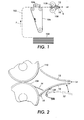
- FIG. 1 is an elevational view of some basic elements of an electrostatographic p rinter, illustrating a practical problem addressed by the present invention.
- Blank sheets are drawn one at a time from a supply stack 100 and conveyed, by known means, through a paper path 102 along a process direction P.
- marking material forming an image is electrostatically transferred to each sheet by one or more corotrons 106 or equivalent devices.
- the sheet is sent through fuser rolls 108 and 110. After fusing, the sheet can be sent on for further processing, such as stapling or binding.
- the sheets pass through the post-fuser path which is of a general funnel shape, such as formed by surfaces of baffles 10 and 12, whereby the vertical width of the path decreases to a relatively narrow slot 14, through which the sheet can be directed to a subsequent processing station.
- the post-fuser path which is of a general funnel shape, such as formed by surfaces of baffles 10 and 12, whereby the vertical width of the path decreases to a relatively narrow slot 14, through which the sheet can be directed to a subsequent processing station.
- a problem can occur if the subsequent processing station following slot 14 is unable to accept input of a sheet, such as if the station is malfunctioning. If a sheet S cannot be accepted through slot 14 and is nonetheless pushed forward by the motion of fuser rolls 108, 110, the sheet S will jam and be compacted between surfaces formed by baffles 10 and 12.
- the funnel-like surfaces of the baffles 10, 12 tend to exacerbate a jamming problem, because the shape causes a very compact accordion-folding of the moving sheet.
- the post-fuser path will fill up quickly with one or more sheets, and the compaction of sheets is liable to damage the hardware around baffles 10 and 12.
- the present invention is directed toward avoiding and obviating damage that can be caused in a post-fuser path in a printing apparatus, or indeed any post-roller path in any apparatus which feeds sheet material.
- an apparatus useful in moving sheets comprising a first roller and a second roller, forming a nip therebetween; means defining a substantially enclosed post-roller path d ownstream of t he n ip along a p rocess d irection toward a n output opening; and opening means for increasing a size of the post-roller path.
- the detecting means including a first monitor for determining a presence of a sheet upstream of the nip along the process direction and a second monitor for determining a presence of a sheet downstream of the output opening along the process direction.
- first and second rollers are fuser rollers.
- the apparatus further comprises a charge-retentive member upstream of the nip.
- FIG. 2 is an elevational view of a post-fuser path in an electrostatographic printer, showing one embodiment of the present invention.
- surfaces defining the post-fuser path to the output opening, or slot, 14 are defined by what can be called plates or "baffles" 10 and 12.
- baffles 10 and 12 are shown as smooth plates in the illustrated embodiments, either of the surfaces converging toward slot 14 can be effectively formed by fingers, ridges, etc., or to some extent by surfaces of neighboring hardware.
- the baffles 10 and 12 form a funnel in the vertical direction, wherein the vertical cross-section of the post-fuser path decreases along the process direction. More broadly, the surfaces of baffles 10 and 12 in effect substantially enclose the post-fuser path for purposes of directing sheets from the nip between rolls 108 and 110 to the slot 14.
- one or more stripper fingers such as 16, which have the purpose of stripping sheets from the image-side (in this case, the lower side) of sheets emerging from the nip between rolls 108 and 110.
- stripper fingers and their associated mounts are likely to be damaged by the impaction of sheets within the post-fuser path.
- the lower baffle 10 is pivotably mounted, such as on hinge 18, within the body of the printing machine, and thus provides a movable surface defining the post-fuser path.
- the baffle 10 is held in a basic position by a spring force provided by a spring 20, which can be a spring of any type, and could include, for example, a counterweight system to provide the spring force.
- a spring force provided by a spring 20, which can be a spring of any type, and could include, for example, a counterweight system to provide the spring force.
- a spring force provided by a spring 20, which can be a spring of any type, and could include, for example, a counterweight system to provide the spring force.
- any downward force greater than the spring force of spring 20 will cause the baffle 10 to be pushed downward, and, as shown, increase a size of or in other words "open” the post-fuser path.
- the downward force would of course be provided by the presence of any sheets stuck in the post-fuser path, or in other words a "
- a spring force associated with spring 20 is chosen based on the expected force of sheets being crumpled by jamming within the post-fuser path, which in turn may be affected by, for instance, the speed of sheets being fed through fuser rolls 108, 110.
- FIG 3 shows another embodiment of the present invention.
- the lower baffle 10 is supported in its basic upward position by a flexible linkage generally indicated as 30.
- the linkage 30 is in turn held in place by a trip member indicated as 32.
- a portion 34 of trip member 32 extends through an opening 11 in baffle 10 and into the post-fuser path, and is thus positioned to contact a jammed sheet in the post-fuser path.
- trip member 32 will assume the position shown in phantom as 32'.
- baffle 10 When this occurs, linkage 30 is no longer supported by trip member 32 and will then flex in the direction shown by arrow 36. When linkage 30 thus flexes, baffle 10 will move downward, in a similar manner as in the Figure 2 embodiment, and the volume of the post-fuser path will open, as described above, to avoid compaction and provide easy removal of crumpled sheets. After crumpled sheets are removed, baffle 10 can be returned to its basic, upward position, and trip member can be reset to once again support flexible linkage 30.
- Figure 3 shows one arrangement of hardware to enable a "trip" for opening the volume in the post-fuser path
- other mechanical arrangements having substantially the same effect would be apparent to one of skill in the art.
- Such arrangements may include springs or equivalent elements to enhance performance, either in determining under what conditions b affle 10 should move downwards, and/or to facilitate a reset of baffle 10 to its basic position.
- FIG. 4 shows another embodiment of the present invention.
- the position of lower baffle 10 is directly controlled by an electronic control system, here indicated as 40.
- control system 40 can be embodied as a routine within a larger control system governing the entire printing apparatus.
- jamming conditions within the post-fuser path can be inferred by monitoring the behavior of sheets passing into the fuser nip between rolls 108 and 110 and exiting through slot 14.
- a monitor 42 (which may be of any variety used in determining sheet position, such as a mechanical sensor or an optical sensor) monitors the feeding of sheets into the fuser, and if the apparatus is working properly, a sheet detected at monitor 42 should be detected at a monitor 44, disposed along paper path 102 just after slot 14, within a predetermined time window thereafter. If a sheet detected by monitor 42 is not matched by a subsequent detection of the sheet by monitor 44, the condition is consistent with a jam in the post-fuser path. Control system 40, detecting this condition, then causes baffle 10 to move to a downward position which opens the post-fuser path. The downward movement of baffle 10 can be performed by an electromechanical actuator 46 of any type, such as an electromagnetic plunger or servomotor.
- the illustrated embodiments of the present invention are directed toward avoiding and obviating damage that can be caused in a post-fuser path in a printing apparatus, the invention can be applied to any post-roller path in any apparatus which feeds sheet material.
Landscapes
- Engineering & Computer Science (AREA)
- Mechanical Engineering (AREA)
- Physics & Mathematics (AREA)
- General Physics & Mathematics (AREA)
- Controlling Sheets Or Webs (AREA)
- Paper Feeding For Electrophotography (AREA)
- Separation, Sorting, Adjustment, Or Bending Of Sheets To Be Conveyed (AREA)
- Fixing For Electrophotography (AREA)
Abstract
Description
- The present invention relates to printing apparatus, in particular to clearance of jammed sheets as could be found in the post-fuser path of a xerographic printer or copier.
- In electrophotographic printers commonly in use today, a charge-retentive member is charged to a uniform potential and thereafter exposed to a light image of an original document to be reproduced. The exposure discharges the charge-retentive surface in exposed or background areas and creates an electrostatic latent image on the member which corresponds to the image areas contained within the original document. Subsequently, the electrostatic latent image on the charge-retentive surface is made visible by developing the image with developing powder referred to in the art as toner. Most development systems employ a developer material which comprises both charged carrier particles and charged toner particles which triboelectrically adhere to the carrier particles. During development the toner particles are attracted from the carrier particles by the charge pattern of the image areas on the charge-retentive area to form a powder image on the photoconductive area. This image is subsequently transferred to a support surface, such as copy paper, to which it is permanently affixed by heating or by the application of pressure. Following transfer of the toner image to a support surface, the charge-retentive member is cleaned of any residual toner that may remain thereon in preparation for the next imaging cycle.
- One a pproach to fixing, or "fusing," the toner image is applying heat and pressure by passing the print sheet containing the unfused toner images between a pair of opposed roller members at least one of which is internally heated. During this procedure, the temperature of the toner material is elevated to a temperature at which the toner material coalesces and becomes tacky. This heating causes the toner to flow to some extent into the fibers or heated. During this procedure, the temperature of the toner material is elevated to a temperature at which the toner material coalesces and becomes tacky. This heating causes the toner to flow to some extent into the fibers or pores of the sheet. Thereafter, as the toner material cools, solidification of the toner material causes the toner material to become bonded to the sheet.
- After the fusing step, it is common that the resulting output sheet be fed to a subsequent processing station, such as an inverter, collator, stapler, booklet maker, etc. In order to direct a sheet emerging from the fuser rolls to the next processing station, it is common that the volume of space immediately downstream of the fuser in the process direction, which can be called the "post-fuser path" be effectively shaped in a funnel configuration, so that a sheet passing through the post-fuser path is directed toward a fairly narrow opening, such as toward a stapler.
- Figure 1 is an elevational view of some basic elements of an electrostatographic p rinter, illustrating a practical problem addressed by the present invention. Blank sheets are drawn one at a time from a
supply stack 100 and conveyed, by known means, through apaper path 102 along a process direction P. At a charge-retentive surface such as onphotoreceptor 104, marking material forming an image is electrostatically transferred to each sheet by one ormore corotrons 106 or equivalent devices. Following transfer, the sheet is sent throughfuser rolls - Following the fuser along process direction P, it is typical that the sheets pass through the post-fuser path which is of a general funnel shape, such as formed by surfaces of
baffles narrow slot 14, through which the sheet can be directed to a subsequent processing station. - As can be seen in the Figure, a problem can occur if the subsequent processing
station following slot 14 is unable to accept input of a sheet, such as if the station is malfunctioning. If a sheet S cannot be accepted throughslot 14 and is nonetheless pushed forward by the motion offuser rolls baffles baffles baffles - The present invention is directed toward avoiding and obviating damage that can be caused in a post-fuser path in a printing apparatus, or indeed any post-roller path in any apparatus which feeds sheet material.
- According to one aspect of the present invention, there is provided an apparatus useful in moving sheets, comprising a first roller and a second roller, forming a nip therebetween; means defining a substantially enclosed post-roller path d ownstream of t he n ip along a p rocess d irection toward a n output opening; and opening means for increasing a size of the post-roller path.
- In a further embodiment the detecting means including a first monitor for determining a presence of a sheet upstream of the nip along the process direction and a second monitor for determining a presence of a sheet downstream of the output opening along the process direction.
- In a further embodiment the first and second rollers are fuser rollers.
- In a further embodiment the apparatus further comprises a charge-retentive member upstream of the nip.
Further embodiments are defined in the dependent claims. -
- Figure 1 is an elevational view of elements of an electrostatographic printer in the prior art, illustrating a problem addressed by the present invention.
- Figure 2 is an elevational view of a post-fuser path in an electrostatographic printer, showing one embodiment of the present invention.
- Figure 3 is an elevational view of a post-fuser path in an electrostatographic printer, showing another embodiment of the present invention.
- Figure 4 is an elevational view of a post-fuser path in an electrostatographic printer, showing another embodiment of the present invention.
-
- In the various Figures, like numerals indicate functionally analogous elements.
- Figure 2 is an elevational view of a post-fuser path in an electrostatographic printer, showing one embodiment of the present invention. At the exit side of the fusing apparatus formed largely by
rolls baffles slot 14 can be effectively formed by fingers, ridges, etc., or to some extent by surfaces of neighboring hardware.) As can be seen, in a basic state, thebaffles baffles rolls slot 14. - In a typical fuser apparatus, there is further provided one or more stripper fingers such as 16, which have the purpose of stripping sheets from the image-side (in this case, the lower side) of sheets emerging from the nip between
rolls - According to the Figure 2 embodiment, the
lower baffle 10 is pivotably mounted, such as onhinge 18, within the body of the printing machine, and thus provides a movable surface defining the post-fuser path. Further, thebaffle 10 is held in a basic position by a spring force provided by aspring 20, which can be a spring of any type, and could include, for example, a counterweight system to provide the spring force. As can be seen by the "down" or "open" position of the baffle indicated as 10', any downward force greater than the spring force ofspring 20 will cause thebaffle 10 to be pushed downward, and, as shown, increase a size of or in other words "open" the post-fuser path. The downward force would of course be provided by the presence of any sheets stuck in the post-fuser path, or in other words a "jam condition," such as shown in Figure 1 above. - By thus "opening" the post-fuser path, first, more volume is available to avoid further compaction of sheets fed into the post-fuser path; and, second, the crumpled jammed sheets can be relatively easily removed by hand from the post-fuser path. In this embodiment, after the crumpled sheets are removed from the post-fuser path,
spring 20 will returnbaffle 10 to its basic position. - In the Figure 2 embodiment, a spring force associated with
spring 20 is chosen based on the expected force of sheets being crumpled by jamming within the post-fuser path, which in turn may be affected by, for instance, the speed of sheets being fed throughfuser rolls - Figure 3 shows another embodiment of the present invention. Instead of being springably mounted as in the previous embodiment, in Figure 3 the
lower baffle 10 is supported in its basic upward position by a flexible linkage generally indicated as 30. Thelinkage 30 is in turn held in place by a trip member indicated as 32. Aportion 34 oftrip member 32 extends through anopening 11 inbaffle 10 and into the post-fuser path, and is thus positioned to contact a jammed sheet in the post-fuser path. When the post-fuser path fills up with a crumpled sheet during a jam condition, eventually the sheet will push downportion 34, and, as shown in the Figure,trip member 32 will assume the position shown in phantom as 32'. When this occurs,linkage 30 is no longer supported bytrip member 32 and will then flex in the direction shown byarrow 36. Whenlinkage 30 thus flexes,baffle 10 will move downward, in a similar manner as in the Figure 2 embodiment, and the volume of the post-fuser path will open, as described above, to avoid compaction and provide easy removal of crumpled sheets. After crumpled sheets are removed,baffle 10 can be returned to its basic, upward position, and trip member can be reset to once again supportflexible linkage 30. - Although Figure 3 shows one arrangement of hardware to enable a "trip" for opening the volume in the post-fuser path, other mechanical arrangements having substantially the same effect would be apparent to one of skill in the art. Such arrangements may include springs or equivalent elements to enhance performance, either in determining under what conditions b
affle 10 should move downwards, and/or to facilitate a reset ofbaffle 10 to its basic position. - Figure 4 shows another embodiment of the present invention. In this embodiment, the position of
lower baffle 10 is directly controlled by an electronic control system, here indicated as 40. Of course controlsystem 40 can be embodied as a routine within a larger control system governing the entire printing apparatus. In this embodiment, jamming conditions within the post-fuser path can be inferred by monitoring the behavior of sheets passing into the fuser nip betweenrolls slot 14. Briefly, a monitor 42 (which may be of any variety used in determining sheet position, such as a mechanical sensor or an optical sensor) monitors the feeding of sheets into the fuser, and if the apparatus is working properly, a sheet detected atmonitor 42 should be detected at amonitor 44, disposed alongpaper path 102 just afterslot 14, within a predetermined time window thereafter. If a sheet detected bymonitor 42 is not matched by a subsequent detection of the sheet bymonitor 44, the condition is consistent with a jam in the post-fuser path.Control system 40, detecting this condition, then causesbaffle 10 to move to a downward position which opens the post-fuser path. The downward movement ofbaffle 10 can be performed by anelectromechanical actuator 46 of any type, such as an electromagnetic plunger or servomotor. - Although the illustrated embodiments of the present invention are directed toward avoiding and obviating damage that can be caused in a post-fuser path in a printing apparatus, the invention can be applied to any post-roller path in any apparatus which feeds sheet material.
Claims (10)
- An apparatus useful in moving sheets, comprising:a first roller and a second roller, forming a nip therebetween;means defining a substantially enclosed post-roller path downstream of the nip along a process direction toward an output opening; andopening means for increasing a size of the post-roller path.
- The apparatus of claim 1, wherein a dimension of the post-roller path decreases from the nip to the output opening.
- The apparatus of claim 1, further comprising
detecting means for detecting a jam condition within the post-roller path; and
wherein the opening means increase a size of the post-roller path in response to detecting a jam condition. - The apparatus of claim 1, the means defining the post-roller path including at least one movable surface.
- The apparatus of claim 4, further comprising at least one spring for holding the movable surface in a basic position with a predetermined spring force.
- The apparatus of claim 4, the opening means including moving means for moving the movable surface.
- The apparatus of claim 6, the moving means including an electromechanical actuator.
- The apparatus of claim 1, the detecting means including a member positioned for contacting a jammed sheet in the post-roller path.
- The apparatus of claim 1, the detecting means including at least one monitor for determining a presence of a sheet upstream of the nip along the process direction.
- The apparatus of claim 1, the detecting means including at least one monitor for determining a presence of a sheet downstream of the output opening along the process direction.
Applications Claiming Priority (2)
| Application Number | Priority Date | Filing Date | Title |
|---|---|---|---|
| US10/022,899 US6640059B2 (en) | 2001-12-20 | 2001-12-20 | Apparatus for facilitating jam clearance in a printer |
| US22899 | 2008-01-23 |
Publications (2)
| Publication Number | Publication Date |
|---|---|
| EP1324146A1 true EP1324146A1 (en) | 2003-07-02 |
| EP1324146B1 EP1324146B1 (en) | 2006-04-05 |
Family
ID=21812004
Family Applications (1)
| Application Number | Title | Priority Date | Filing Date |
|---|---|---|---|
| EP02028663A Expired - Lifetime EP1324146B1 (en) | 2001-12-20 | 2002-12-20 | Jam clearance in a post-fuser path in a xerographic printing apparatus |
Country Status (5)
| Country | Link |
|---|---|
| US (1) | US6640059B2 (en) |
| EP (1) | EP1324146B1 (en) |
| JP (1) | JP2003195590A (en) |
| BR (1) | BR0205404A (en) |
| DE (1) | DE60210404T2 (en) |
Cited By (1)
| Publication number | Priority date | Publication date | Assignee | Title |
|---|---|---|---|---|
| TWI408521B (en) * | 2008-03-03 | 2013-09-11 | Lite On Electronics Guangzhou | Fuser mechanism |
Families Citing this family (9)
| Publication number | Priority date | Publication date | Assignee | Title |
|---|---|---|---|---|
| US6823167B1 (en) * | 2003-04-30 | 2004-11-23 | Xerox Corporation | Paper sensitive spring loaded prefuser paper guide |
| US20050008408A1 (en) * | 2003-07-11 | 2005-01-13 | Kabushiki Kaisha Toshiba | Fixing device and image forming apparatus |
| US20060088346A1 (en) * | 2004-10-25 | 2006-04-27 | Xerox Corporation | Floating stripper finger assembly and a fuser having same |
| JP4834485B2 (en) * | 2005-09-16 | 2011-12-14 | 株式会社リコー | Transfer fixing device and image forming apparatus |
| JP2009210822A (en) * | 2008-03-04 | 2009-09-17 | Kyocera Mita Corp | Image forming apparatus |
| CN102950919B (en) * | 2011-08-18 | 2015-09-02 | 山东新北洋信息技术股份有限公司 | Paper delivery mechanism, printing equipment and terminal device |
| JP2016084207A (en) * | 2014-10-24 | 2016-05-19 | キヤノン株式会社 | Sheet conveyance device and image formation apparatus |
| US11220119B2 (en) | 2017-11-20 | 2022-01-11 | Hewlett-Packard Development Company, L.P. | Media sensing |
| JP7454940B2 (en) * | 2019-12-19 | 2024-03-25 | 株式会社Pfu | Media transport device |
Citations (6)
| Publication number | Priority date | Publication date | Assignee | Title |
|---|---|---|---|---|
| US4497569A (en) * | 1982-09-21 | 1985-02-05 | Xerox Corporation | Copy processing system for a reproduction machine |
| JPS62102266A (en) * | 1985-10-30 | 1987-05-12 | Kyocera Corp | Electrophotographing device |
| JPS6387464A (en) * | 1986-09-30 | 1988-04-18 | Fuji Xerox Co Ltd | Jam preventing device of fixing device |
| EP0278237A1 (en) * | 1987-02-13 | 1988-08-17 | International Business Machines Corporation | Roll fuser jam clearance mechanism |
| EP0870707A1 (en) * | 1997-04-11 | 1998-10-14 | Xerox Corporation | Jam clearance features for modular-type decurler having continuous bending nip |
| US5839032A (en) * | 1996-03-08 | 1998-11-17 | Ricoh Company, Ltd. | Image forming apparatus having selectably controlled sheet discharge paths |
Family Cites Families (4)
| Publication number | Priority date | Publication date | Assignee | Title |
|---|---|---|---|---|
| US5245395A (en) | 1991-09-06 | 1993-09-14 | Xerox Corporation | Recording substrate wave restrictor |
| EP0934555B1 (en) * | 1996-10-22 | 2002-01-09 | Océ Printing Systems GmbH | Shutter device enabling access to paper path in single sheet printers and photocopiers |
| US5822668A (en) | 1997-04-11 | 1998-10-13 | Xerox Coporation | Fuser subsystem module for an electrophotographic printer which pivots open for jam clearance |
| JP3965024B2 (en) * | 2000-03-09 | 2007-08-22 | 株式会社リコー | Fixing apparatus and image forming apparatus |
-
2001
- 2001-12-20 US US10/022,899 patent/US6640059B2/en not_active Expired - Lifetime
-
2002
- 2002-12-13 JP JP2002361872A patent/JP2003195590A/en active Pending
- 2002-12-17 BR BR0205404-3A patent/BR0205404A/en not_active Application Discontinuation
- 2002-12-20 DE DE60210404T patent/DE60210404T2/en not_active Expired - Lifetime
- 2002-12-20 EP EP02028663A patent/EP1324146B1/en not_active Expired - Lifetime
Patent Citations (6)
| Publication number | Priority date | Publication date | Assignee | Title |
|---|---|---|---|---|
| US4497569A (en) * | 1982-09-21 | 1985-02-05 | Xerox Corporation | Copy processing system for a reproduction machine |
| JPS62102266A (en) * | 1985-10-30 | 1987-05-12 | Kyocera Corp | Electrophotographing device |
| JPS6387464A (en) * | 1986-09-30 | 1988-04-18 | Fuji Xerox Co Ltd | Jam preventing device of fixing device |
| EP0278237A1 (en) * | 1987-02-13 | 1988-08-17 | International Business Machines Corporation | Roll fuser jam clearance mechanism |
| US5839032A (en) * | 1996-03-08 | 1998-11-17 | Ricoh Company, Ltd. | Image forming apparatus having selectably controlled sheet discharge paths |
| EP0870707A1 (en) * | 1997-04-11 | 1998-10-14 | Xerox Corporation | Jam clearance features for modular-type decurler having continuous bending nip |
Non-Patent Citations (2)
| Title |
|---|
| PATENT ABSTRACTS OF JAPAN vol. 011, no. 311 (P - 625) 12 October 1987 (1987-10-12) * |
| PATENT ABSTRACTS OF JAPAN vol. 012, no. 315 (M - 735) 26 August 1988 (1988-08-26) * |
Cited By (1)
| Publication number | Priority date | Publication date | Assignee | Title |
|---|---|---|---|---|
| TWI408521B (en) * | 2008-03-03 | 2013-09-11 | Lite On Electronics Guangzhou | Fuser mechanism |
Also Published As
| Publication number | Publication date |
|---|---|
| DE60210404D1 (en) | 2006-05-18 |
| DE60210404T2 (en) | 2006-09-07 |
| US20030118357A1 (en) | 2003-06-26 |
| BR0205404A (en) | 2004-07-20 |
| JP2003195590A (en) | 2003-07-09 |
| US6640059B2 (en) | 2003-10-28 |
| EP1324146B1 (en) | 2006-04-05 |
Similar Documents
| Publication | Publication Date | Title |
|---|---|---|
| US5138390A (en) | Cleaning sheet for fixating rotational member and image forming apparatus having fixating rotational member | |
| JP3386235B2 (en) | Transfer paper guide device | |
| US4408757A (en) | Sheet separating device | |
| US6640059B2 (en) | Apparatus for facilitating jam clearance in a printer | |
| JPH09297481A (en) | Image forming device | |
| EP1333339B1 (en) | Stripper fingers and associated mounts for a xerographic fusing apparatus | |
| US6782228B1 (en) | Intermittent stripper fingers and baffle for stripping copy media from a heated fuser roll | |
| US20110305490A1 (en) | Dual position pre-transfer assembly | |
| US11835902B2 (en) | Image reading apparatus and image forming system | |
| US7263322B2 (en) | Fuser smart cleaning and oiling assembly | |
| EP1376254B1 (en) | Jam clearance member for media in an electrophotographic apparatus | |
| US5241354A (en) | Symmetrically flexible sheet stripping apparatus | |
| JPH10297796A (en) | Self-adjustment sheet baffle device | |
| JP5910225B2 (en) | Fixing device and image forming apparatus | |
| US20150117917A1 (en) | Print medium supporting device and image forming apparatus having the same | |
| US8422932B2 (en) | Active sheet stripping from belt via small radius feature | |
| JPH0233175A (en) | Improved type fixing apparatus system | |
| US5920746A (en) | Transfer apparatus | |
| EP1431840B1 (en) | Toner image transfer apparatus | |
| US7310491B2 (en) | Non-gouging sheet stripper assembly | |
| US6265694B1 (en) | Sheet stripping method and apparatus and a fusing mechanism including same | |
| JP2004212755A (en) | Image forming device | |
| JPH09288432A (en) | Image forming device | |
| JPH0554455U (en) | Image forming device | |
| JP2535025Y2 (en) | Recording paper transport device |
Legal Events
| Date | Code | Title | Description |
|---|---|---|---|
| PUAI | Public reference made under article 153(3) epc to a published international application that has entered the european phase |
Free format text: ORIGINAL CODE: 0009012 |
|
| AK | Designated contracting states |
Designated state(s): AT BE BG CH CY CZ DE DK EE ES FI FR GB GR IE IT LI LU MC NL PT SE SI SK TR |
|
| AX | Request for extension of the european patent |
Extension state: AL LT LV MK RO |
|
| 17P | Request for examination filed |
Effective date: 20040102 |
|
| AKX | Designation fees paid |
Designated state(s): DE FR GB |
|
| 17Q | First examination report despatched |
Effective date: 20041011 |
|
| GRAP | Despatch of communication of intention to grant a patent |
Free format text: ORIGINAL CODE: EPIDOSNIGR1 |
|
| GRAS | Grant fee paid |
Free format text: ORIGINAL CODE: EPIDOSNIGR3 |
|
| GRAA | (expected) grant |
Free format text: ORIGINAL CODE: 0009210 |
|
| AK | Designated contracting states |
Kind code of ref document: B1 Designated state(s): DE FR GB |
|
| REG | Reference to a national code |
Ref country code: GB Ref legal event code: FG4D |
|
| REF | Corresponds to: |
Ref document number: 60210404 Country of ref document: DE Date of ref document: 20060518 Kind code of ref document: P |
|
| ET | Fr: translation filed | ||
| PLBE | No opposition filed within time limit |
Free format text: ORIGINAL CODE: 0009261 |
|
| STAA | Information on the status of an ep patent application or granted ep patent |
Free format text: STATUS: NO OPPOSITION FILED WITHIN TIME LIMIT |
|
| 26N | No opposition filed |
Effective date: 20070108 |
|
| REG | Reference to a national code |
Ref country code: FR Ref legal event code: PLFP Year of fee payment: 14 |
|
| REG | Reference to a national code |
Ref country code: FR Ref legal event code: PLFP Year of fee payment: 15 |
|
| PGFP | Annual fee paid to national office [announced via postgrant information from national office to epo] |
Ref country code: GB Payment date: 20161128 Year of fee payment: 15 Ref country code: DE Payment date: 20161121 Year of fee payment: 15 Ref country code: FR Payment date: 20161121 Year of fee payment: 15 |
|
| REG | Reference to a national code |
Ref country code: DE Ref legal event code: R119 Ref document number: 60210404 Country of ref document: DE |
|
| GBPC | Gb: european patent ceased through non-payment of renewal fee |
Effective date: 20171220 |
|
| REG | Reference to a national code |
Ref country code: FR Ref legal event code: ST Effective date: 20180831 |
|
| PG25 | Lapsed in a contracting state [announced via postgrant information from national office to epo] |
Ref country code: FR Free format text: LAPSE BECAUSE OF NON-PAYMENT OF DUE FEES Effective date: 20180102 Ref country code: DE Free format text: LAPSE BECAUSE OF NON-PAYMENT OF DUE FEES Effective date: 20180703 |
|
| PG25 | Lapsed in a contracting state [announced via postgrant information from national office to epo] |
Ref country code: GB Free format text: LAPSE BECAUSE OF NON-PAYMENT OF DUE FEES Effective date: 20171220 |