EP1324057B1 - Electronic energy meter, in particular domestic meter - Google Patents
Electronic energy meter, in particular domestic meter Download PDFInfo
- Publication number
- EP1324057B1 EP1324057B1 EP02024724.3A EP02024724A EP1324057B1 EP 1324057 B1 EP1324057 B1 EP 1324057B1 EP 02024724 A EP02024724 A EP 02024724A EP 1324057 B1 EP1324057 B1 EP 1324057B1
- Authority
- EP
- European Patent Office
- Prior art keywords
- meter
- current
- current transformers
- module
- plug
- Prior art date
- Legal status (The legal status is an assumption and is not a legal conclusion. Google has not performed a legal analysis and makes no representation as to the accuracy of the status listed.)
- Expired - Lifetime
Links
- 230000005611 electricity Effects 0.000 description 13
- 238000004804 winding Methods 0.000 description 4
- 239000011162 core material Substances 0.000 description 2
- 238000009434 installation Methods 0.000 description 2
- NIXOWILDQLNWCW-UHFFFAOYSA-N Acrylic acid Chemical compound OC(=O)C=C NIXOWILDQLNWCW-UHFFFAOYSA-N 0.000 description 1
- 230000005540 biological transmission Effects 0.000 description 1
- 239000004020 conductor Substances 0.000 description 1
- 238000005265 energy consumption Methods 0.000 description 1
- 125000000524 functional group Chemical group 0.000 description 1
Images
Classifications
-
- G—PHYSICS
- G01—MEASURING; TESTING
- G01D—MEASURING NOT SPECIALLY ADAPTED FOR A SPECIFIC VARIABLE; ARRANGEMENTS FOR MEASURING TWO OR MORE VARIABLES NOT COVERED IN A SINGLE OTHER SUBCLASS; TARIFF METERING APPARATUS; MEASURING OR TESTING NOT OTHERWISE PROVIDED FOR
- G01D4/00—Tariff metering apparatus
- G01D4/02—Details
-
- G—PHYSICS
- G01—MEASURING; TESTING
- G01R—MEASURING ELECTRIC VARIABLES; MEASURING MAGNETIC VARIABLES
- G01R22/00—Arrangements for measuring time integral of electric power or current, e.g. electricity meters
-
- G—PHYSICS
- G01—MEASURING; TESTING
- G01R—MEASURING ELECTRIC VARIABLES; MEASURING MAGNETIC VARIABLES
- G01R22/00—Arrangements for measuring time integral of electric power or current, e.g. electricity meters
- G01R22/06—Arrangements for measuring time integral of electric power or current, e.g. electricity meters by electronic methods
- G01R22/061—Details of electronic electricity meters
- G01R22/065—Details of electronic electricity meters related to mechanical aspects
-
- G—PHYSICS
- G01—MEASURING; TESTING
- G01R—MEASURING ELECTRIC VARIABLES; MEASURING MAGNETIC VARIABLES
- G01R11/00—Electromechanical arrangements for measuring time integral of electric power or current, e.g. of consumption
- G01R11/02—Constructional details
- G01R11/12—Arrangements of bearings
- G01R11/14—Arrangements of bearings with magnetic relief
-
- Y—GENERAL TAGGING OF NEW TECHNOLOGICAL DEVELOPMENTS; GENERAL TAGGING OF CROSS-SECTIONAL TECHNOLOGIES SPANNING OVER SEVERAL SECTIONS OF THE IPC; TECHNICAL SUBJECTS COVERED BY FORMER USPC CROSS-REFERENCE ART COLLECTIONS [XRACs] AND DIGESTS
- Y04—INFORMATION OR COMMUNICATION TECHNOLOGIES HAVING AN IMPACT ON OTHER TECHNOLOGY AREAS
- Y04S—SYSTEMS INTEGRATING TECHNOLOGIES RELATED TO POWER NETWORK OPERATION, COMMUNICATION OR INFORMATION TECHNOLOGIES FOR IMPROVING THE ELECTRICAL POWER GENERATION, TRANSMISSION, DISTRIBUTION, MANAGEMENT OR USAGE, i.e. SMART GRIDS
- Y04S20/00—Management or operation of end-user stationary applications or the last stages of power distribution; Controlling, monitoring or operating thereof
- Y04S20/30—Smart metering, e.g. specially adapted for remote reading
Definitions
- the invention relates to an electronic electricity meter, in particular household meter according to claim 1.
- the so-called calibration validity period of electronic electricity meters is limited in time. To check the meter this is to be removed or replaced. For this purpose, the supply connection of the pantograph must be de-energized.
- the calibration law does not allow the functions of an electricity meter to be modified by a software update or to correct software errors. Again, this requires the installation and removal of the electricity meter.
- Conventional electronic electricity meters have a current transformer or sensor, as well as an electronic measuring module. These two elements form a unit that measures and displays energy consumption.
- the publication EP 0 913 696 A2 shows a modular electronic electricity meter with a module M, which contains both a counter module and current transformer.
- the module is inserted in a first housing.
- Another housing contains a card for additional functions.
- connection device for a three-phase meter has become known.
- Power terminals for connection to the four conductors of a power network and two external power converters are formed on an adapter terminal block.
- the adapter terminal block continues to point Counter-side terminals, which are connected by means of pins with the terminals of a three-phase meter.
- the mains and meter-side connections are connected so that the two external current transformers are connected to the three power meters of the three-phase meter according to an aron circuit.
- the invention has for its object to provide an electronic electricity meter, in particular household meter, which does not have the disadvantages mentioned above.
- a separate meter module is housed within a sealable meter base unit.
- the counter module is can be plugged together with the meter base unit via a plug connector.
- the meter base unit in turn has a sealable housing in which the electronic meter module is housed.
- the interface between the current transformer on the one hand and counter module on the other hand is clearly defined and therefore meets the accuracy requirements of the counter when using different counter modules.
- Module housings and meter housings can be secured by a metering test, as required by the regulations.
- the meter base unit with the integrated current transformers can be certified indefinitely or at least have a significantly longer calibration validity than electronic meters. They can therefore remain indefinitely in the installation.
- the current transformer remote from the counter module can be regarded as separate or external current transformers and be treated as current transformers.
- the meter module is a self-contained electronic electricity meter with its own housing that allows replacement without having to unplug the meter base unit.
- the counter module thus falls under the calibration law for electronic electricity meters.
- the current transformers are current-compensated.
- the transmission ratio of primary current to secondary current is clearly coupled to the ratio of primary to secondary winding (compensation winding). Changes in the core properties or the contact resistance of the connectors are eliminated by the loop gain of the compensation control in a wide range.
- the current transformers are idle. Due to the core material used and the dielectric strength, the windings are made idle-proof. Thus, during module replacement, it is not necessary to short-circuit the windings of the current transformer.
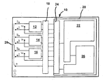
- the single figure shows the schematic representation of the functional groups of the electronic electricity meter according to the invention.
- the box 10 is intended to indicate a sealable housing for an electronic electricity meter.
- the housing 10 Within the housing 10 are three current transformers 12, 14 and 16, which may be arranged on a circuit board, not shown.
- the board also has seven terminals for fixed connection to the mains. In the present case, therefore, a three-phase meter is indicated. It is understood that a normal AC meter can be formed in the same way.
- first connector part 18 At the output of the current transformer 12 to 16 there is a first connector part 18, the details of which are not shown. Also, the connector part 18 is fixedly mounted on the board, not shown.
- a second housing 20 which is detachably housed in the housing 10. It is also sealable.
- a counter module 22 which is connected to a connector part 24 in the housing 20.
- the plug connection parts 18 and 24 can establish an electrical connection between the current transformers 12 to 16 and the counter module by simply plugging together.
- housing 20 In the housing 20 are also additional modules 26 for the supply and operation of the counter module, which need not be discussed in detail. This is part of the state of the art.
- the housing 20 can be readily removed, e.g. for replacement with another housing containing a counter module.
- the terminals, which are designated together with 28, remain firmly connected to the network.
- the current transformers 12 to 16 are designed so that they do not have to be short-circuited when idling.
Description
Die Erfindung bezieht sich auf einen elektronischen Elektrizitätszähler, insbesondere Haushaltszähler nach dem Anspruch 1.The invention relates to an electronic electricity meter, in particular household meter according to claim 1.
Die so genannte Eichgültigkeitsdauer von elektronischen Elektrizitätszählern ist zeitlich begrenzt. Zur Überprüfung des Zählers ist dieser auszubauen bzw. auszuwechseln. Hierfür muss der Versorgungsanschluss des Stromabnehmers spannungslos geschaltet werden.The so-called calibration validity period of electronic electricity meters is limited in time. To check the meter this is to be removed or replaced. For this purpose, the supply connection of the pantograph must be de-energized.
Das Eichgesetz erlaubt nicht, die Funktionen eines Elektrizitätszählers durch ein Software Update zu modifizieren oder Softwarefehler zu korrigieren. Auch hierfür ist ein Ein- und Ausbau des Elektrizitätszählers erforderlich.The calibration law does not allow the functions of an electricity meter to be modified by a software update or to correct software errors. Again, this requires the installation and removal of the electricity meter.
Herkömmliche elektronische Elektrizitätszähler haben einen Stromwandler bzw. - sensor, sowie ein elektronisches Messmodul. Diese beiden Elemente bilden eine Einheit, durch die der Energieverbrauch gemessen und angezeigt wird.Conventional electronic electricity meters have a current transformer or sensor, as well as an electronic measuring module. These two elements form a unit that measures and displays energy consumption.
Die Druckschrift
Aus der Druckschrift
Der Erfindung liegt die Aufgabe zugrunde, einen elektronischen Elektrizitätszähler, insbesondere Haushaltszähler, zu schaffen, der die oben genannten Nachteile nicht aufweist.The invention has for its object to provide an electronic electricity meter, in particular household meter, which does not have the disadvantages mentioned above.
Diese Aufgabe wird durch einen elektronischen Elektrizitätszahler mit den Merkmalen des Anspruchs 1 gelöst.This object is achieved by an electronic electricity payer with the features of claim 1.
Bei dem erfindungsgemäßen Eiektrizitatszähler ist ein separates Zählermodul innerhalb einer plombierbaren Zählerbasiseinheit untergebracht. Das Zählermodul ist über einen Steckverbinder mit der Zählerbasiseinheit zusammensteckbar. Die Zählerbasiseinheit weist ihrerseits ein plombierbares Gehäuse auf, in dem auch das elektronische Zählermodul untergebracht ist. Eine solche Anordnung weist etliche Vorteile auf.In the Eiektrizitatszähler invention a separate meter module is housed within a sealable meter base unit. The counter module is can be plugged together with the meter base unit via a plug connector. The meter base unit in turn has a sealable housing in which the electronic meter module is housed. Such an arrangement has several advantages.
Bei einem Wechsel des Zählermoduls muss die Stromversorgung des Stromabnehmers nicht unterbrochen werden. Das Wechseln des Zählermoduls hat die gleiche Bedeutung wie das Wechseln des Zählers in einem klassischen Messsatz, bei dem Stromwandler und Elektrizitätszähler zwei voneinander unabhängige Geräte sind.When changing the counter module, the power supply of the pantograph must not be interrupted. Replacing the meter module has the same meaning as changing the meter in a classic meter set where the CTs and electricity meters are two independent units.
Die Schnittstelle zwischen Stromwandler einerseits und Zählermodul andererseits ist eindeutig definiert und genügt mithin den Genauigkeitsanforderungen des Zählers bei Verwendung unterschiedlicher Zählermodule.The interface between the current transformer on the one hand and counter module on the other hand is clearly defined and therefore meets the accuracy requirements of the counter when using different counter modules.
Modulgehäuse und Zählergehäuse sind eichtechnisch absicherbar, wie dies den Bestimmungen zufolge erforderlich ist.Module housings and meter housings can be secured by a metering test, as required by the regulations.
Die Zählerbasiseinheit mit den integrierten Stromwandlem sind zeitlich unbegrenzt beglaubigungsfähig oder verfügen zumindest über eine deutlich längere Eichgültigkeit als elektronische Zähler. Sie können daher auf unbestimmte Dauer in der Installation verbleiben. Somit können die vom Zählermodul abgesetzten Stromwandler wie separate bzw. externe Stromwandler betrachtet werden und eichrechtlich wie Stromwandler behandelt werden.The meter base unit with the integrated current transformers can be certified indefinitely or at least have a significantly longer calibration validity than electronic meters. They can therefore remain indefinitely in the installation. Thus, the current transformer remote from the counter module can be regarded as separate or external current transformers and be treated as current transformers.
Das Zählermodul ist ein eigenständiger elektronischer Elektrizitätszähler mit einem eigenen Gehäuse, das ein Austauschen ermöglicht, ohne dass die Zählerbasiseinheit vom Netz getrennt werden muss. Das Zählermodul fällt somit unter das Eichrecht für elektronische Elektrizitätszähler.The meter module is a self-contained electronic electricity meter with its own housing that allows replacement without having to unplug the meter base unit. The counter module thus falls under the calibration law for electronic electricity meters.
Nach einer Ausgestaltung der Erfindung sind die Stromwandler stromkompensiert. Das Übersetzungsverhältnis von Primärstrom zu Sekundärstrom ist eindeutig an das Verhältnis von Primär- zu Sekundärwicklung (Kompensationswicklung) gekoppelt. Änderungen der Kerneigenschaften oder des Übergangswiderstandes der Steckverbindungen werden durch die Schleifenverstärkung der Kompensationsregelung in einem weiten Bereich eliminiert.According to one embodiment of the invention, the current transformers are current-compensated. The transmission ratio of primary current to secondary current is clearly coupled to the ratio of primary to secondary winding (compensation winding). Changes in the core properties or the contact resistance of the connectors are eliminated by the loop gain of the compensation control in a wide range.
Bei der Erfindung sind die Stromwandler leerlauffest. Durch das eingesetzte Kernmaterial und die Spannungsfestigkeit werden die Wicklungen leerlauffest gemacht. Somit ist während des Modulaustausches nicht erforderlich, die Wicklungen des Stromwandlers kurzzuschließen.In the invention, the current transformers are idle. Due to the core material used and the dielectric strength, the windings are made idle-proof. Thus, during module replacement, it is not necessary to short-circuit the windings of the current transformer.
Ein Ausführungsbeispiel der Erfindung wird nachfolgend anhand einer Zeichnung näher erläutert.An embodiment of the invention will be explained in more detail with reference to a drawing.
Die einzige Figur zeigt die schematische Darstellung der Funktionsgruppen des erfindungsgemäßen elektronischen Elektrizitätszählers.The single figure shows the schematic representation of the functional groups of the electronic electricity meter according to the invention.
Mit dem Kasten 10 soll ein plombierbares Gehäuse für einen elektronischen Elektrizitätszähler angedeutet sein. Innerhalb des Gehäuses 10 befinden sich drei Stromwandler 12, 14 und 16, die auf einer nicht weiter dargestellten Platine angeordnet sein können. Auf der Platine befinden sich außerdem sieben Klemmen für die feste Verbindung mit dem Stromnetz. Im vorliegenden Fall ist mithin ein Drehstromzähler angedeutet. Es versteht sich, dass in gleicher Weise ein normaler Wechselstromzähler ausgebildet sein kann.The
Am Ausgang der Stromwandler 12 bis 16 befindet sich ein erstes Steckverbindungsteil 18, dessen Einzelheiten nicht weiter dargestellt sind. Auch das Steckverbindungsteil 18 ist auf der nicht gezeigten Platine fest angeordnet.At the output of the
Innerhalb des Gehäuses 10 befindet sich ein zweites Gehäuse 20, das lösbar im Gehäuse 10 untergebracht ist. Es ist ebenfalls plombierbar. Im Gehäuse 20 befindet sich ein Zählermodul 22, das mit einem Steckverbindungsteil 24 im Gehäuse 20 verbunden ist. Die Steckverbindungsteile 18 und 24 können durch ein einfaches Zusammenstecken eine elektrische Verbindung zwischen den Stromwandlern 12 bis 16 und dem Zählermodul herstellen.Within the
Im Gehäuse 20 befinden sich außerdem Zusatzmodule 26 für die Versorgung und den Betrieb des Zählermoduls, worauf im Einzelnen nicht eingegangen werden muss. Dies gehört zum Stand der Technik.In the
Nach dem Öffnen des Gehäuses 10 kann das Gehäuse 20 ohne weiteres entfernt werden, z.B. zum Austausch mit einem anderen ein Zählermodul enthaltendes Gehäuse. Hierbei können die Klemmen, die zusammen mit 28 bezeichnet sind, fest mit dem Netz verbunden bleiben. Die Stromwandler 12 bis 16 sind im Übrigen so ausgelegt, dass sie im Leerlauf nicht kurzgeschlossen werden müssen.After opening the
Claims (2)
- An electronic energy meter, in particular a domestic meter, comprising• current terminals (28),• current transformers (12 to 16), which are connected to a first plug-and-socket connector assembly (18),• an electronic counter module (22), which is connected to a second plug-and-socket connector assembly (24) that can be plugged together with the first plug-and-socket connector assembly (18) for the electric connection of the current transformers (12 to 16) to the counter module (22), characterised in that• the current transformers (12 to 16) are disposed, in a short-circuit proof manner and together with the current terminals (28) and the first plug-and-socket connector assembly (18), in a sealable first case (10) of a meter base unit, and• the electronic counter module (22) is disposed in a separate sealable second case (20), which can be detachably attached in the first case (10).
- The energy counter according to claim 1, characterised in that the current transformers (12 to 16) are current compensated.
Applications Claiming Priority (2)
| Application Number | Priority Date | Filing Date | Title |
|---|---|---|---|
| DE20120947U | 2001-12-24 | ||
| DE20120947U DE20120947U1 (en) | 2001-12-24 | 2001-12-24 | Electronic electricity meter, especially household meter |
Publications (2)
| Publication Number | Publication Date |
|---|---|
| EP1324057A1 EP1324057A1 (en) | 2003-07-02 |
| EP1324057B1 true EP1324057B1 (en) | 2013-05-08 |
Family
ID=7965659
Family Applications (1)
| Application Number | Title | Priority Date | Filing Date |
|---|---|---|---|
| EP02024724.3A Expired - Lifetime EP1324057B1 (en) | 2001-12-24 | 2002-11-06 | Electronic energy meter, in particular domestic meter |
Country Status (2)
| Country | Link |
|---|---|
| EP (1) | EP1324057B1 (en) |
| DE (1) | DE20120947U1 (en) |
Families Citing this family (3)
| Publication number | Priority date | Publication date | Assignee | Title |
|---|---|---|---|---|
| DE10311441B4 (en) * | 2003-03-15 | 2005-03-10 | Emh Elek Zitaetszaehler Gmbh & | Electronic electricity meter |
| DE10311995A1 (en) * | 2003-03-19 | 2004-10-07 | ITF Fröschl GmbH | Exchangeable electronic model for measuring electrical energy / consumption / power |
| CN104391264B (en) * | 2014-12-05 | 2018-08-14 | 上海市计量测试技术研究院 | Multi-function electronic transformer checking system and method for calibration |
Citations (2)
| Publication number | Priority date | Publication date | Assignee | Title |
|---|---|---|---|---|
| DE19653475A1 (en) * | 1996-12-20 | 1998-06-25 | Siemens Ag | Electricity meter arrangement based on four-wire three-phase transformer meter |
| US20010043062A1 (en) * | 1998-03-18 | 2001-11-22 | Reid Drew A. | Modular sensor array, metering device and mounting and connection base |
Family Cites Families (10)
| Publication number | Priority date | Publication date | Assignee | Title |
|---|---|---|---|---|
| DE3933356A1 (en) * | 1989-10-06 | 1991-04-18 | Licentia Gmbh | ELECTRICITY COUNTER |
| GB9306648D0 (en) * | 1993-03-30 | 1993-05-26 | Midlands Electricity Plc | Modular electricity metering |
| EP0649024A1 (en) * | 1993-10-15 | 1995-04-19 | Zellweger Luwa Ag | Static electricity meter |
| DE29613420U1 (en) * | 1996-08-02 | 1996-10-31 | Elektra Tailfingen | Device for measuring and distributing electrical energy |
| DE19712239C1 (en) * | 1997-03-24 | 1998-08-27 | Siemens Ag | Electrical device housing, in particular for a consumption meter |
| WO1999008119A1 (en) * | 1997-08-12 | 1999-02-18 | Siemens Aktiengesellschaft | Electricity meter with a housing, an electric terminal arrangement and a printed circuit board |
| FI105723B (en) * | 1997-10-28 | 2000-09-29 | Enermet Oy | Modular measuring device for measuring electrical energy |
| JP3671706B2 (en) * | 1998-11-25 | 2005-07-13 | 松下電工株式会社 | Electricity meter |
| DE19962435A1 (en) * | 1999-12-22 | 2001-07-05 | Siemens Metering Ag Zug | Electricity meter with an additional computing module |
| DE10022532A1 (en) * | 2000-05-09 | 2000-12-21 | Langmatz Lic Gmbh | Current meter has housing with sealable cover and audio frequency powerline control receiver; meter housing or pref. cover has outwardly open pocket in which receiver can be inserted |
-
2001
- 2001-12-24 DE DE20120947U patent/DE20120947U1/en not_active Expired - Lifetime
-
2002
- 2002-11-06 EP EP02024724.3A patent/EP1324057B1/en not_active Expired - Lifetime
Patent Citations (2)
| Publication number | Priority date | Publication date | Assignee | Title |
|---|---|---|---|---|
| DE19653475A1 (en) * | 1996-12-20 | 1998-06-25 | Siemens Ag | Electricity meter arrangement based on four-wire three-phase transformer meter |
| US20010043062A1 (en) * | 1998-03-18 | 2001-11-22 | Reid Drew A. | Modular sensor array, metering device and mounting and connection base |
Also Published As
| Publication number | Publication date |
|---|---|
| EP1324057A1 (en) | 2003-07-02 |
| DE20120947U1 (en) | 2003-05-08 |
Similar Documents
| Publication | Publication Date | Title |
|---|---|---|
| EP2619595B1 (en) | Measurement system for monitoring at least one phase of a system | |
| DE10041599B4 (en) | Current sensor and electrical circuit using this | |
| EP2407996B1 (en) | Current sensing arrangement in an inverter | |
| DE102011016373A1 (en) | Battery block for use as energy storage in motor car, has contact elements provided at circuit board in sections, and monitoring and balancing circuits in contact with power connector at battery cells on circuit board via contact elements | |
| EP2741054B1 (en) | Smart meter | |
| DE10008602A1 (en) | Data processing apparatus such as personal computer, printer etc. | |
| DE602005006261T2 (en) | EQUIPMENT CONNECTION PART | |
| DE102013106216B4 (en) | Measuring device for current measurement | |
| DE202012010818U1 (en) | Smart meter | |
| EP1324057B1 (en) | Electronic energy meter, in particular domestic meter | |
| EP2745331B1 (en) | Junction box for determining string current in photovoltaic installations | |
| DE102017111245A1 (en) | power distribution | |
| DE10019092A1 (en) | Low voltage circuit breaker with an information store | |
| EP3489696A1 (en) | Current measuring device, series of current measuring devices and method for measuring an electric current | |
| DE10216330B4 (en) | Measuring equipment for process technology with central power supply | |
| EP2191539A2 (en) | Connection module, accumulator module, and assembly formed thereof for a pre-accumulator of a photovoltaic system | |
| EP2626710A1 (en) | Meter support housing for a meter cabinet | |
| EP1460438B1 (en) | Modular electricity meter | |
| AT508106B1 (en) | INVERTER FOR A PHOTOVOLTAIC SYSTEM WITH STRUCTURE MONITORING AND STRUCTURE MONITORING METHOD | |
| DE102004033844A1 (en) | Power supply device for multiple output voltages | |
| EP3986095A1 (en) | Relay assembly | |
| EP2446330A1 (en) | Input/output unit | |
| DE102009015698B4 (en) | Device for adapting the distribution of the conductors of power lines | |
| DE19957980B4 (en) | Electronic electricity meter | |
| DE202004002731U1 (en) | Transducer type electricity meter adapter has a current or voltage transducer, for each phase of a power supply, connected between a measurement transformer and an electrical power meter |
Legal Events
| Date | Code | Title | Description |
|---|---|---|---|
| PUAI | Public reference made under article 153(3) epc to a published international application that has entered the european phase |
Free format text: ORIGINAL CODE: 0009012 |
|
| AK | Designated contracting states |
Designated state(s): AT BE BG CH CY CZ DE DK EE ES FI FR GB GR IE IT LI LU MC NL PT SE SK TR |
|
| AX | Request for extension of the european patent |
Extension state: AL LT LV MK RO SI |
|
| 17P | Request for examination filed |
Effective date: 20030607 |
|
| AKX | Designation fees paid |
Designated state(s): AT CH DE DK LI NL SE |
|
| 17Q | First examination report despatched |
Effective date: 20071018 |
|
| RAP1 | Party data changed (applicant data changed or rights of an application transferred) |
Owner name: EMH METERING GMBH & CO. KG |
|
| REG | Reference to a national code |
Ref country code: DE Ref legal event code: R079 Ref document number: 50215765 Country of ref document: DE Free format text: PREVIOUS MAIN CLASS: G01R0022000000 Ipc: G01R0022060000 |
|
| GRAP | Despatch of communication of intention to grant a patent |
Free format text: ORIGINAL CODE: EPIDOSNIGR1 |
|
| RIC1 | Information provided on ipc code assigned before grant |
Ipc: G01R 22/06 20060101AFI20130206BHEP Ipc: G01D 4/02 20060101ALI20130206BHEP Ipc: G01R 22/00 20060101ALI20130206BHEP |
|
| GRAS | Grant fee paid |
Free format text: ORIGINAL CODE: EPIDOSNIGR3 |
|
| GRAA | (expected) grant |
Free format text: ORIGINAL CODE: 0009210 |
|
| AK | Designated contracting states |
Kind code of ref document: B1 Designated state(s): AT CH DE DK LI NL SE |
|
| REG | Reference to a national code |
Ref country code: CH Ref legal event code: EP Ref country code: CH Ref legal event code: NV Representative=s name: BOHEST AG, CH Ref country code: AT Ref legal event code: REF Ref document number: 611322 Country of ref document: AT Kind code of ref document: T Effective date: 20130515 |
|
| REG | Reference to a national code |
Ref country code: DE Ref legal event code: R096 Ref document number: 50215765 Country of ref document: DE Effective date: 20130704 |
|
| REG | Reference to a national code |
Ref country code: NL Ref legal event code: VDEP Effective date: 20130508 |
|
| PG25 | Lapsed in a contracting state [announced via postgrant information from national office to epo] |
Ref country code: SE Free format text: LAPSE BECAUSE OF FAILURE TO SUBMIT A TRANSLATION OF THE DESCRIPTION OR TO PAY THE FEE WITHIN THE PRESCRIBED TIME-LIMIT Effective date: 20130508 |
|
| PG25 | Lapsed in a contracting state [announced via postgrant information from national office to epo] |
Ref country code: DK Free format text: LAPSE BECAUSE OF FAILURE TO SUBMIT A TRANSLATION OF THE DESCRIPTION OR TO PAY THE FEE WITHIN THE PRESCRIBED TIME-LIMIT Effective date: 20130508 |
|
| PG25 | Lapsed in a contracting state [announced via postgrant information from national office to epo] |
Ref country code: NL Free format text: LAPSE BECAUSE OF FAILURE TO SUBMIT A TRANSLATION OF THE DESCRIPTION OR TO PAY THE FEE WITHIN THE PRESCRIBED TIME-LIMIT Effective date: 20130508 |
|
| PLBE | No opposition filed within time limit |
Free format text: ORIGINAL CODE: 0009261 |
|
| STAA | Information on the status of an ep patent application or granted ep patent |
Free format text: STATUS: NO OPPOSITION FILED WITHIN TIME LIMIT |
|
| 26N | No opposition filed |
Effective date: 20140211 |
|
| REG | Reference to a national code |
Ref country code: DE Ref legal event code: R097 Ref document number: 50215765 Country of ref document: DE Effective date: 20140211 |
|
| REG | Reference to a national code |
Ref country code: CH Ref legal event code: PCAR Free format text: NEW ADDRESS: HOLBEINSTRASSE 36-38, 4051 BASEL (CH) |
|
| PGFP | Annual fee paid to national office [announced via postgrant information from national office to epo] |
Ref country code: AT Payment date: 20141124 Year of fee payment: 13 |
|
| REG | Reference to a national code |
Ref country code: AT Ref legal event code: MM01 Ref document number: 611322 Country of ref document: AT Kind code of ref document: T Effective date: 20151106 |
|
| PG25 | Lapsed in a contracting state [announced via postgrant information from national office to epo] |
Ref country code: AT Free format text: LAPSE BECAUSE OF NON-PAYMENT OF DUE FEES Effective date: 20151106 |
|
| PGFP | Annual fee paid to national office [announced via postgrant information from national office to epo] |
Ref country code: CH Payment date: 20181126 Year of fee payment: 17 |
|
| PGFP | Annual fee paid to national office [announced via postgrant information from national office to epo] |
Ref country code: DE Payment date: 20190116 Year of fee payment: 17 |
|
| REG | Reference to a national code |
Ref country code: DE Ref legal event code: R119 Ref document number: 50215765 Country of ref document: DE |
|
| REG | Reference to a national code |
Ref country code: CH Ref legal event code: PL |
|
| PG25 | Lapsed in a contracting state [announced via postgrant information from national office to epo] |
Ref country code: CH Free format text: LAPSE BECAUSE OF NON-PAYMENT OF DUE FEES Effective date: 20191130 Ref country code: LI Free format text: LAPSE BECAUSE OF NON-PAYMENT OF DUE FEES Effective date: 20191130 |
|
| PG25 | Lapsed in a contracting state [announced via postgrant information from national office to epo] |
Ref country code: DE Free format text: LAPSE BECAUSE OF NON-PAYMENT OF DUE FEES Effective date: 20200603 |