EP1324010A1 - Angular position sensing apparatus and method - Google Patents
Angular position sensing apparatus and method Download PDFInfo
- Publication number
- EP1324010A1 EP1324010A1 EP02079830A EP02079830A EP1324010A1 EP 1324010 A1 EP1324010 A1 EP 1324010A1 EP 02079830 A EP02079830 A EP 02079830A EP 02079830 A EP02079830 A EP 02079830A EP 1324010 A1 EP1324010 A1 EP 1324010A1
- Authority
- EP
- European Patent Office
- Prior art keywords
- rotatable
- sensor assembly
- sensor
- rotatable body
- finger
- Prior art date
- Legal status (The legal status is an assumption and is not a legal conclusion. Google has not performed a legal analysis and makes no representation as to the accuracy of the status listed.)
- Withdrawn
Links
- 238000000034 method Methods 0.000 title claims description 20
- 230000004044 response Effects 0.000 claims abstract description 23
- 230000008878 coupling Effects 0.000 claims description 21
- 238000010168 coupling process Methods 0.000 claims description 21
- 238000005859 coupling reaction Methods 0.000 claims description 21
- 238000009434 installation Methods 0.000 claims description 18
- 150000001875 compounds Chemical class 0.000 claims description 4
- 230000002512 anti-withdrawal effect Effects 0.000 claims description 3
- 238000000926 separation method Methods 0.000 claims description 2
- 238000010276 construction Methods 0.000 description 4
- 238000011156 evaluation Methods 0.000 description 4
- 230000007246 mechanism Effects 0.000 description 4
- 230000009977 dual effect Effects 0.000 description 2
- 238000004519 manufacturing process Methods 0.000 description 2
- 238000012986 modification Methods 0.000 description 2
- 230000004048 modification Effects 0.000 description 2
- 239000000725 suspension Substances 0.000 description 2
- 230000005355 Hall effect Effects 0.000 description 1
- 230000005540 biological transmission Effects 0.000 description 1
- 230000001808 coupling effect Effects 0.000 description 1
- 230000003993 interaction Effects 0.000 description 1
- 230000000737 periodic effect Effects 0.000 description 1
- 230000002093 peripheral effect Effects 0.000 description 1
- 230000000750 progressive effect Effects 0.000 description 1
Images


Classifications
-
- B—PERFORMING OPERATIONS; TRANSPORTING
- B62—LAND VEHICLES FOR TRAVELLING OTHERWISE THAN ON RAILS
- B62D—MOTOR VEHICLES; TRAILERS
- B62D15/00—Steering not otherwise provided for
- B62D15/02—Steering position indicators ; Steering position determination; Steering aids
-
- G—PHYSICS
- G01—MEASURING; TESTING
- G01D—MEASURING NOT SPECIALLY ADAPTED FOR A SPECIFIC VARIABLE; ARRANGEMENTS FOR MEASURING TWO OR MORE VARIABLES NOT COVERED IN A SINGLE OTHER SUBCLASS; TARIFF METERING APPARATUS; MEASURING OR TESTING NOT OTHERWISE PROVIDED FOR
- G01D18/00—Testing or calibrating apparatus or arrangements provided for in groups G01D1/00 - G01D15/00
-
- G—PHYSICS
- G01—MEASURING; TESTING
- G01D—MEASURING NOT SPECIALLY ADAPTED FOR A SPECIFIC VARIABLE; ARRANGEMENTS FOR MEASURING TWO OR MORE VARIABLES NOT COVERED IN A SINGLE OTHER SUBCLASS; TARIFF METERING APPARATUS; MEASURING OR TESTING NOT OTHERWISE PROVIDED FOR
- G01D5/00—Mechanical means for transferring the output of a sensing member; Means for converting the output of a sensing member to another variable where the form or nature of the sensing member does not constrain the means for converting; Transducers not specially adapted for a specific variable
- G01D5/26—Mechanical means for transferring the output of a sensing member; Means for converting the output of a sensing member to another variable where the form or nature of the sensing member does not constrain the means for converting; Transducers not specially adapted for a specific variable characterised by optical transfer means, i.e. using infrared, visible, or ultraviolet light
- G01D5/32—Mechanical means for transferring the output of a sensing member; Means for converting the output of a sensing member to another variable where the form or nature of the sensing member does not constrain the means for converting; Transducers not specially adapted for a specific variable characterised by optical transfer means, i.e. using infrared, visible, or ultraviolet light with attenuation or whole or partial obturation of beams of light
- G01D5/34—Mechanical means for transferring the output of a sensing member; Means for converting the output of a sensing member to another variable where the form or nature of the sensing member does not constrain the means for converting; Transducers not specially adapted for a specific variable characterised by optical transfer means, i.e. using infrared, visible, or ultraviolet light with attenuation or whole or partial obturation of beams of light the beams of light being detected by photocells
- G01D5/347—Mechanical means for transferring the output of a sensing member; Means for converting the output of a sensing member to another variable where the form or nature of the sensing member does not constrain the means for converting; Transducers not specially adapted for a specific variable characterised by optical transfer means, i.e. using infrared, visible, or ultraviolet light with attenuation or whole or partial obturation of beams of light the beams of light being detected by photocells using displacement encoding scales
- G01D5/3473—Circular or rotary encoders
Definitions
- This invention relates to a position sensing method and apparatus and particularly to a sensor assembly for sensing the angular position of a rotatable body.
- a control signal representative of the angular position of the steering column.
- This control signal may be used, for example, to control a steer-by-wire steering system, to vary the setting of an active suspension system in response to turning movement of the vehicle, or to control a four-wheel steering system.
- the sensors employed to sense the angular position of a steering column are typically calibrated prior to installation on the steering column and it is imperative that the calibration zero position be maintained between the time that the sensor is calibrated and the time that the sensor is assembled onto the steering column. It is also imperative that, upon installation of the sensor on the steering column, the operative sensor member be free to rotate with the steering column whereby to generate a position signal indicative of the angular position of the steering column.
- This invention relates to an improved position sensor for use with a rotatable body.
- this invention relates to a position sensor having provision to maintain the zero calibration of the sensor prior to installation on the rotatable body and to automatically release the operative element of the sensor for rotation with the rotatable body in response to installation of the sensor on the rotatable body.
- One aspect of the invention relates to a method of mounting a sensor assembly on the rotatable body following calibration of the rotatable element of the sensor assembly.
- the rotatable element is calibrated; the rotatable element is lockingly engaged relative to the sensor housing to maintain the rotatable element in the calibrated position; and, with the rotatable element in the calibrated position, the sensor assembly is mounted on the rotatable body while simultaneously keying the rotatable element to the rotatable body and releasing the rotatable element from locking engagement with the sensor housing.
- This methodology maintains the zero calibration of the sensor prior to installation on the rotatable body and automatically releases the rotatable element of the sensor for turning movement with the rotatable body in response to mounting of the sensor on a rotatable body.
- the sensor assembly includes a connector member connected to the rotatable element and including a key structure for keying the connector member and rotatable element to the rotatable body and an anti-rotation structure for lockingly engaging the connector member to the sensor housing; the anti-rotation structure functions prior to the mounting step to maintain the calibrated position of the rotatable element; and, during the mounting step, the key structure functions to key the connector member and rotatable element to the rotatable body and the rotatable body is operative to move the anti-rotation structure out of locking engagement with a sensor housing.
- This methodology provides a ready and effective mechanism for maintaining zero calibration while automatically releasing the rotatable element of the sensor for rotation with the rotatable body in response to installation of the sensor on the rotatable body.
- the connector member comprises a ring member having an annular main body portion;
- the key structure comprises a key finger projecting from the main body portion and sized for coaction with a keyway on the rotatable body;
- the anti-rotation structure comprises an anti-rotation finger projecting from the main body portion at a location spaced circumferentially from the key finger and sized for receipt in a notch in the sensor housing.
- the anti-rotation finger includes a locking portion for engagement with the notch in the sensor housing and a release portion; and the release portion is operative during mounting of the sensor assembly on the rotatable body to move the locking portion out of engagement with the sensor housing notch in response to engagement of the release portion by the rotatable body.
- This specific connector member construction facilitates the step of releasing the rotatable element from locking engagement with the sensor housing in response to mounting of the sensor assembly on the rotatable body.
- the rotatable element of the sensor comprises a ring gear having circumferentially spaced teeth on its external periphery and circumferentially spaced notches on its internal periphery; and the connector member further includes a plurality of circumferentially spaced coupling fingers projecting from the main body portion for respective receipt in the notches in the internal periphery of the ring gear.
- the rotatable body comprises the steering column of a motor vehicle and the sensor assembly is operative to sense the angular position of the steering column and generate a control signal representative of the angular position of the steering column.
- the sensor assembly is of a type including a sensor housing, a rotatable element mounted in the housing, and means operative to sense the angular position of the rotatable element and generate a control signal representative of the angular position of the rotatable element.
- the sensor assembly further includes a connector member for selectively interconnecting the rotatable body, the sensor housing, and the rotatable element and the connector member includes a coupling structure for coupling the connector member to the rotatable element, a key structure for keying the connector member to the rotatable body in response to mounting of the sensor assembly on the rotatable body, an anti-rotation structure for lockingly engaging the connector member to the sensor housing to preclude rotation of the connector member and rotatable element relative to the sensor housing, and a release structure operative in response to mounting of the sensor assembly on the rotatable body to release the anti-rotation structure from locking engagement with the sensor housing and allow rotation of the rotatable element with the rotatable body.
- the recited connector member will be seen to provide a convenient means of maintaining the initial zero calibration of the sensor prior to installation on the rotatable body and to further provide automatic means to release the anti-rotation structure from locking engagement with the sensor housing in response to mounting of the sensor on the rotatable body.
- the connector member comprises a ring member adapted to be positioned in surrounding relation to the rotatable body; the ring member includes an annular main body portion; the key structure comprises a key finger projecting from the main body portion for coaction with a keyway on the rotatable body; the anti-rotation structure comprises an anti-rotation finger projecting from the main body portion at a location spaced circumferentially from the key finger and coacting with a notch in the sensor housing; and the release structure comprises a release portion of the anti-rotation finger positioned in the path of the rotatable body as the sensor assembly is mounted on the rotatable body and operative in response to engagement with the rotatable body to move the anti-rotation finger out of the notch of the sensor assembly.
- the specific connector member construction facilitates the selective coaction between the connector member, the sensor housing, the rotatable element, and the rotatable body.
- a pivot point is defined at the juncture of the anti-rotation finger and the main body portion and the point of engagement between the release portion of the anti-rotation finger and the rotatable body is spaced inwardly from the pivot point so that the anti-rotation finger is pivoted about the pivot point in response to engagement by the rotatable body.
- the finger comprises a compound finger including a first finger portion extending inwardly from the main body portion and a second finger portion doubled over with respect to the first finger portion so as to extend outwardly to define a free end adapted to coact with the notch in the sensor housing.
- This specific finger construction provides both a locking and a release function in a single finger configuration.
- the first portion of the compound finger extends downwardly and inwardly and the second portion extends upwardly and outwardly and has a length extending a length of the first portion so as to position the free end thereof above the main body portion to facilitate engagement with the sensor housing notch.
- the coupling structure comprises a plurality of circumferentially spaced coupling fingers projecting from the main body portion for engagement with the rotatable element and the coupling fingers are further operative to center the sensor assembly with respect to the rotatable body as the sensor assembly is mounted on the rotatable body.
- the coupling fingers will be seen to enable the connector member to perform the dual functions of coupling the connector member and the rotatable element and centering the sensor assembly on the rotatable body as the sensor assembly is mounted on the rotatable body.
- FIG. 1 The position sensor of the invention is seen in Figure 1 in association with a motor vehicle 10 shown fragmentary.
- Motor vehicle 10 includes a steering wheel 12, a steering column 14, an instrument panel 16, and a firewall 18.
- Steering column 14 is supported in known manner from the instrument panel 16 by a bracket structure 20 and extends through the firewall 18 for coaction in known manner with a steering mechanism.
- a sensor assembly 22 is provided in surrounding relation to steering column 14 to sense the angular position of the steering column and to generate a control signal representative of the angular position of the steering column.
- Sensor assembly 22 may be mounted as shown proximate the firewall 18 of the vehicle or, alternatively, as shown in dash lines, may be mounted proximate the steering wheel 12.
- Sensor assembly 22 ( Figures 2 and 3) comprises a sensor housing 24 an operative rotatable element in the form of a ring gear 26, a secondary gear 28 meshingly engaging with ring gear 26, an angle sensor 30 tracking the angular position of secondary gear 28, an electronic evaluation circuit 32 receiving input from the angle sensor 30, and a connector member 34.
- the sensor assembly 22 functions to track the angular position of the steering column 14 and generate a control signal representative of this angular position for transmittal to further vehicle control apparatus such as, for example, control apparatus constituting a steer-by-wire system for the vehicle.
- Housing 24 ( Figure 2) has a key hole shaped configuration and includes an annular generally cylindrical main body portion 24a and a stem portion 24b extending radially from the cylindrical main body portion 24a.
- Main body portion 24a defines a generally circular central opening 40 sized to pass steering column 14, and includes an upper annular wall portion 24c, a lower annular wall portion 24d, an outer peripheral annular wall 24e, an upper annular lip 24f defining opening 40, and a lower annular lip 24g further defining opening 40.
- An anti-rotation detent or notch 24h is provided in upper lip24f.
- Ring gear 26 is mounted within housing 24 and specifically is mounted in the space between the lower edge 24i of lip 24f and the upper edge 24j of lip 24g in concentrical relation to the central axis 42 of the main body portion of the housing.
- Ring gear 26 includes a plurality of circumferentially spaced teeth 26a on its external periphery and a plurality of circumferentially spaced notches 26b on its internal periphery.
- Second ring gear 28 is positioned within the housing 24 in meshing engagement with ring gear 26 and includes a plurality of circumferentially spaced teeth 28a. There may be, for example, a gear ratio of approximately 5.2:1.0 between ring gear 26 and secondary gear 28.
- Angle sensor 30 comprises a periodic angle sensor and may, for example, comprise a Hall Effect sensor.
- Electronic evaluation circuit 32 is of known form and is operative to receive input from angle sensor 30 and perform calculations required for determining the angular position of the steering column 14.
- This invention concerns primarily connector member 34 ( Figures 4 - 7) and the manner in which the connector member interconnects the various elements of the sensor assembly and facilitates the installation of the sensor assembly on the steering column while preserving the previously determined zero position calibration of the sensor.
- Connector member 34 comprises a grip ring member including an annular main body portion 34a, a key structure constituted by a key finger 34b projecting generally upwardly from main body portion 34a for coaction with an axial keyway 14a on the steering column, an anti-rotation structure in the form of an anti-rotation finger 34c projecting from the main body portion 34a at a location spaced circumferentially from key finger 34b for coaction with notch 24h in the sensor housing, a plurality of circumferentially spaced anti-withdrawal fingers 34d projecting generally outwardly from the main body portion for engagement with the sensor housing to preclude inadvertent separation of the ring member from the sensor housing, and a plurality of circumferentially spaced coupling fingers 34d extending generally downwardly from the main body portion for respective receipt in ring gear notches 26b whereby to couple the ring member to the ring gear.
- Anti-rotation finger 34c comprises a compound finger including a first finger portion 34e extending inwardly from the main body portion and a second finger portion 34f doubled over with respect to the first finger portion so as to extend outwardly and defining a free end 34g for coaction with notch 24f in the sensor housing.
- the first finger portion 34e extends downwardly and radially inwardly from the main body portion and the second finger portion 34f extends upwardly and outwardly and has a length exceeding the length of the first finger portion so as to position the free end 34g above the main body portion to facilitate engagement with the sensor housing notch 36f.
- a pivot point 34h will be seen to be defined at the juncture of the finger portion 34e and the main body portion 34a and the point of engagement 42 between the free end 14b of the steering column 14 and the anti-rotation finger 34c as the sensor assembly is installed on the steering column 14 is spaced radially inwardly from the pivot point so that the anti-rotation finger is pivoted about the pivot point 34h in response to engagement by the steering column 14 from the relaxed, pre-installation seen in Figure 5 to the displaced installation position seen Figures 4 and 7.
- the anti-withdrawal fingers 34c are positioned beneath the lip 24i of the main body housing portion to preclude withdrawal of the ring member from the housing and the coupling fingers 34d are respectively received in the notches 26b of the ring member whereby to couple the ring member 34 to the ring gear 26.
- the sensor assembly is calibrated to a zero position and this zero position is defined and maintained by engagement of the free end 34g of the anti-rotation finger 34c in the anti-rotation notch 24h of the sensor housing.
- This positive engagement of the anti-rotation finger in the anti-rotation notch eliminates the possibility that the zero position calibration of the sensor assembly will be disturbed during subsequent handling of the sensor assembly and, specifically, ensures that the zero calibration position will not be disturbed during shipment of the sensor assembly from the point of manufacture of the sensor assembly to a subsequent assembly point which may comprise, for example, an assembly point for the steering column assembly or, alternatively, may comprise a final assembly location.
- the sensor assembly Upon arrival at the sensor assembly at the steering column or the final assembly location, the sensor assembly is mounted on the steering column 14.
- FIG. 5 The mounting sequence is illustrated in successive Figures 5, 6 and 7, with Figure 5 showing the disposition of ring member 34 immediately prior to the installation of the sensor assembly on the steering column, Figure 6 showing the disposition of the ring member relative to the steering column upon initial contact between the free end 14a of the steering column and the anti-rotation finger 34c, and Figure 7 illustrating the installed disposition of the ring member on the steering column.
- the initial contact between the ring member and the steering column comprises sliding entry of the key finger 34b of the ring member into steering column keyway 14a whereby to locate the ring member circumferentially relative to the steering column and key the ring member to the steering column.
- anti-rotation finger 34c defines both a locking portion or structure for locking engagement with the sensor housing and a release portion or structure for coaction with the steering column to release the locking structure.
- the ring member turns with the steering column by virtue of the interaction of the key finger 34b and the keyway 14b; the ring gear 26 turns with the ring member by virtue of the coupling action of the coupling fingers 34d; the secondary gear 28 is driven by the ring member; the extent of rotation of the secondary gear is tracked by the angle sensor 30; the angle sensor 30 generates a signal for transmission to the electronic evaluation circuit 32; and the electronic evaluation circuit 32 evaluates the information received from angle sensor 30 and transmits the evaluated information, for example by way of leads 42, to an appropriate on-board vehicle mechanism such for example as a steer-by-wire system, a four wheel steering system, or active suspension system.
- an appropriate on-board vehicle mechanism such for example as a steer-by-wire system, a four wheel steering system, or active suspension system.
- the invention will seen to provide a method and apparatus whereby a sensor assembly may be calibrated and thereafter installed on a steering column or other rotatable body in a manner to ensure that the calibration is maintained between calibration and installation and in a manner to automatically release the operative sensor mechanism for free rotation with the rotatable body in response to installation on the rotatable body.
Landscapes
- Engineering & Computer Science (AREA)
- Physics & Mathematics (AREA)
- General Physics & Mathematics (AREA)
- Chemical & Material Sciences (AREA)
- Combustion & Propulsion (AREA)
- Transportation (AREA)
- Mechanical Engineering (AREA)
- Length Measuring Devices With Unspecified Measuring Means (AREA)
Abstract
A sensor assembly (22) for sensing the angular position of a rotatable body (14) such as a motor vehicle steering column. The sensor assembly (22) includes a ring gear (26) which is zero calibrated upon assembly of the sensor assembly (22). The sensor assembly (22) further includes a ring member (34) which functions to lock the ring gear (26) to the sensor housing (24) to maintain the zero calibration between the time of calibration and the subsequent mounting of the sensor assembly (22) on the steering column (14) and further functions to release the ring gear (26) for free rotation with the steering column (14) in response to mounting of the sensor assembly (22) on the steering column (14). The locking and releasing functions of the sensor assembly (22) are performed by a finger structure (34c) of the ring member (34) which includes a free end (34g) which is engaged in a notch (24h) in the sensor housing (24) upon calibration of the sensor assembly (22) to maintain the calibration setting and which further includes a release portion (34f) which is engaged by the steering column (14) as the sensor assembly (22) is mounted on the steering column (14) to pivot the finger structure in (34c) a sense to move the free end (34g) of the finger structure (34c) out of the housing notch (24h).
Description
- This invention relates to a position sensing method and apparatus and particularly to a sensor assembly for sensing the angular position of a rotatable body.
- It is desirable in many applications to sense the angular position of a rotatable body. For example, it is desirable in a motor vehicle to sense the angular position of the steering column and generally a control signal representative of the angular position of the steering column. This control signal may be used, for example, to control a steer-by-wire steering system, to vary the setting of an active suspension system in response to turning movement of the vehicle, or to control a four-wheel steering system.
- The sensors employed to sense the angular position of a steering column are typically calibrated prior to installation on the steering column and it is imperative that the calibration zero position be maintained between the time that the sensor is calibrated and the time that the sensor is assembled onto the steering column. It is also imperative that, upon installation of the sensor on the steering column, the operative sensor member be free to rotate with the steering column whereby to generate a position signal indicative of the angular position of the steering column.
- In one prior art design, these dual requirements have been satisfied by the use of an anti-rotation pin which lockingly interconnects the sensor operative member to the sensor housing to maintain the zero calibration position and which is removed following installation of the sensor on the steering column to allow the sensor operative member to freely rotate with the steering column. Whereas this pin design satisfies both requirements, the provision of the pin complicates the sensor design and increases the assembly time. The pin design also introduces the possibility that the installer may forget to remove the pin following installation of the sensor on the steering column.
- This invention relates to an improved position sensor for use with a rotatable body.
- More specifically this invention relates to a position sensor having provision to maintain the zero calibration of the sensor prior to installation on the rotatable body and to automatically release the operative element of the sensor for rotation with the rotatable body in response to installation of the sensor on the rotatable body.
- One aspect of the invention relates to a method of mounting a sensor assembly on the rotatable body following calibration of the rotatable element of the sensor assembly. According to the invention methodology, the rotatable element is calibrated; the rotatable element is lockingly engaged relative to the sensor housing to maintain the rotatable element in the calibrated position; and, with the rotatable element in the calibrated position, the sensor assembly is mounted on the rotatable body while simultaneously keying the rotatable element to the rotatable body and releasing the rotatable element from locking engagement with the sensor housing. This methodology maintains the zero calibration of the sensor prior to installation on the rotatable body and automatically releases the rotatable element of the sensor for turning movement with the rotatable body in response to mounting of the sensor on a rotatable body.
- According to a further aspect of the invention methodology, the sensor assembly includes a connector member connected to the rotatable element and including a key structure for keying the connector member and rotatable element to the rotatable body and an anti-rotation structure for lockingly engaging the connector member to the sensor housing; the anti-rotation structure functions prior to the mounting step to maintain the calibrated position of the rotatable element; and, during the mounting step, the key structure functions to key the connector member and rotatable element to the rotatable body and the rotatable body is operative to move the anti-rotation structure out of locking engagement with a sensor housing. This methodology provides a ready and effective mechanism for maintaining zero calibration while automatically releasing the rotatable element of the sensor for rotation with the rotatable body in response to installation of the sensor on the rotatable body.
- According to further aspect of the invention methodology, the connector member comprises a ring member having an annular main body portion; the key structure comprises a key finger projecting from the main body portion and sized for coaction with a keyway on the rotatable body; and the anti-rotation structure comprises an anti-rotation finger projecting from the main body portion at a location spaced circumferentially from the key finger and sized for receipt in a notch in the sensor housing. This specific connector member construction provides a ready and effective means of carrying out the invention methodology.
- According to a further feature of the invention, the anti-rotation finger includes a locking portion for engagement with the notch in the sensor housing and a release portion; and the release portion is operative during mounting of the sensor assembly on the rotatable body to move the locking portion out of engagement with the sensor housing notch in response to engagement of the release portion by the rotatable body. This specific connector member construction facilitates the step of releasing the rotatable element from locking engagement with the sensor housing in response to mounting of the sensor assembly on the rotatable body.
- According to a further feature of the invention methodology, the rotatable element of the sensor comprises a ring gear having circumferentially spaced teeth on its external periphery and circumferentially spaced notches on its internal periphery; and the connector member further includes a plurality of circumferentially spaced coupling fingers projecting from the main body portion for respective receipt in the notches in the internal periphery of the ring gear. This arrangement provides a ready and effective means of coupling the connector member to the ring member to facilitate carrying out the invention methodology.
- In the preferred embodiment of the invention the rotatable body comprises the steering column of a motor vehicle and the sensor assembly is operative to sense the angular position of the steering column and generate a control signal representative of the angular position of the steering column.
- With respect to the apparatus aspect of the invention, the sensor assembly is of a type including a sensor housing, a rotatable element mounted in the housing, and means operative to sense the angular position of the rotatable element and generate a control signal representative of the angular position of the rotatable element.
- According to the invention, the sensor assembly further includes a connector member for selectively interconnecting the rotatable body, the sensor housing, and the rotatable element and the connector member includes a coupling structure for coupling the connector member to the rotatable element, a key structure for keying the connector member to the rotatable body in response to mounting of the sensor assembly on the rotatable body, an anti-rotation structure for lockingly engaging the connector member to the sensor housing to preclude rotation of the connector member and rotatable element relative to the sensor housing, and a release structure operative in response to mounting of the sensor assembly on the rotatable body to release the anti-rotation structure from locking engagement with the sensor housing and allow rotation of the rotatable element with the rotatable body. The recited connector member will be seen to provide a convenient means of maintaining the initial zero calibration of the sensor prior to installation on the rotatable body and to further provide automatic means to release the anti-rotation structure from locking engagement with the sensor housing in response to mounting of the sensor on the rotatable body.
- According to further apparatus feature of the invention, the connector member comprises a ring member adapted to be positioned in surrounding relation to the rotatable body; the ring member includes an annular main body portion; the key structure comprises a key finger projecting from the main body portion for coaction with a keyway on the rotatable body; the anti-rotation structure comprises an anti-rotation finger projecting from the main body portion at a location spaced circumferentially from the key finger and coacting with a notch in the sensor housing; and the release structure comprises a release portion of the anti-rotation finger positioned in the path of the rotatable body as the sensor assembly is mounted on the rotatable body and operative in response to engagement with the rotatable body to move the anti-rotation finger out of the notch of the sensor assembly. The specific connector member construction facilitates the selective coaction between the connector member, the sensor housing, the rotatable element, and the rotatable body.
- According to a further apparatus aspect of the invention, a pivot point is defined at the juncture of the anti-rotation finger and the main body portion and the point of engagement between the release portion of the anti-rotation finger and the rotatable body is spaced inwardly from the pivot point so that the anti-rotation finger is pivoted about the pivot point in response to engagement by the rotatable body. This specific pivotal arrangement provides a ready and effective means of unlocking the rotatable element of the sensor from the sensor housing as the sensor is mounted on the rotatable body.
- According to a further apparatus aspect of the invention, the finger comprises a compound finger including a first finger portion extending inwardly from the main body portion and a second finger portion doubled over with respect to the first finger portion so as to extend outwardly to define a free end adapted to coact with the notch in the sensor housing. This specific finger construction provides both a locking and a release function in a single finger configuration.
- According to a further apparatus aspect of the invention, the first portion of the compound finger extends downwardly and inwardly and the second portion extends upwardly and outwardly and has a length extending a length of the first portion so as to position the free end thereof above the main body portion to facilitate engagement with the sensor housing notch.
- According to a further apparatus aspect of the invention, the coupling structure comprises a plurality of circumferentially spaced coupling fingers projecting from the main body portion for engagement with the rotatable element and the coupling fingers are further operative to center the sensor assembly with respect to the rotatable body as the sensor assembly is mounted on the rotatable body. The coupling fingers will be seen to enable the connector member to perform the dual functions of coupling the connector member and the rotatable element and centering the sensor assembly on the rotatable body as the sensor assembly is mounted on the rotatable body.
- The description herein makes reference to the accompanying drawings wherein like reference numerals refer to like parts throughout the several views, and wherein:
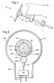
- Figure 1 is a fragmentary schematic view of a motor vehicle illustrating the steering column, instrument panel and fire wall of the vehicle;
- Figure 2 is a perspective view of a sensor assembly according to the invention;
- Figure 3 is a schematic cross sectional view taken on line 3-3 of Figure 2;
- Figure 4 is a perspective view of a connector member employed in the sensor assembly; and
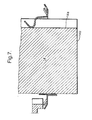
- Figures 5, 6, and 7 are progressive schematic views showing the installation of the sensor assembly on the steering column of the motor vehicle.
-
- Other applications of the present invention will become apparent to those skilled in the art when the following description of the best mode contemplated for practicing the invention is read in conjunction with the accompanying drawings.
- The position sensor of the invention is seen in Figure 1 in association with a
motor vehicle 10 shown fragmentary.Motor vehicle 10 includes asteering wheel 12, asteering column 14, aninstrument panel 16, and a firewall 18.Steering column 14 is supported in known manner from theinstrument panel 16 by abracket structure 20 and extends through the firewall 18 for coaction in known manner with a steering mechanism. - A
sensor assembly 22 according to the invention is provided in surrounding relation tosteering column 14 to sense the angular position of the steering column and to generate a control signal representative of the angular position of the steering column.Sensor assembly 22 may be mounted as shown proximate the firewall 18 of the vehicle or, alternatively, as shown in dash lines, may be mounted proximate thesteering wheel 12. - Sensor assembly 22 (Figures 2 and 3) comprises a
sensor housing 24 an operative rotatable element in the form of aring gear 26, asecondary gear 28 meshingly engaging withring gear 26, anangle sensor 30 tracking the angular position ofsecondary gear 28, anelectronic evaluation circuit 32 receiving input from theangle sensor 30, and aconnector member 34. - In overview, it will be understood that the
sensor assembly 22 functions to track the angular position of thesteering column 14 and generate a control signal representative of this angular position for transmittal to further vehicle control apparatus such as, for example, control apparatus constituting a steer-by-wire system for the vehicle. - Housing 24 (Figure 2) has a key hole shaped configuration and includes an annular generally cylindrical
main body portion 24a and astem portion 24b extending radially from the cylindricalmain body portion 24a. -
Main body portion 24a defines a generally circularcentral opening 40 sized to passsteering column 14, and includes an upperannular wall portion 24c, a lowerannular wall portion 24d, an outer peripheralannular wall 24e, an upperannular lip 24f defining opening 40, and a lowerannular lip 24g further definingopening 40. An anti-rotation detent ornotch 24h is provided in upper lip24f. -
Ring gear 26 is mounted withinhousing 24 and specifically is mounted in the space between thelower edge 24i oflip 24f and theupper edge 24j oflip 24g in concentrical relation to thecentral axis 42 of the main body portion of the housing.Ring gear 26 includes a plurality of circumferentially spacedteeth 26a on its external periphery and a plurality of circumferentially spacednotches 26b on its internal periphery. -
Second ring gear 28 is positioned within thehousing 24 in meshing engagement withring gear 26 and includes a plurality of circumferentially spacedteeth 28a. There may be, for example, a gear ratio of approximately 5.2:1.0 betweenring gear 26 andsecondary gear 28. -
Angle sensor 30 comprises a periodic angle sensor and may, for example, comprise a Hall Effect sensor. -
Electronic evaluation circuit 32 is of known form and is operative to receive input fromangle sensor 30 and perform calculations required for determining the angular position of thesteering column 14. - This invention concerns primarily connector member 34 (Figures 4 - 7) and the manner in which the connector member interconnects the various elements of the sensor assembly and facilitates the installation of the sensor assembly on the steering column while preserving the previously determined zero position calibration of the sensor.
-
Connector member 34 comprises a grip ring member including an annularmain body portion 34a, a key structure constituted by akey finger 34b projecting generally upwardly frommain body portion 34a for coaction with anaxial keyway 14a on the steering column, an anti-rotation structure in the form of ananti-rotation finger 34c projecting from themain body portion 34a at a location spaced circumferentially fromkey finger 34b for coaction withnotch 24h in the sensor housing, a plurality of circumferentially spacedanti-withdrawal fingers 34d projecting generally outwardly from the main body portion for engagement with the sensor housing to preclude inadvertent separation of the ring member from the sensor housing, and a plurality of circumferentially spacedcoupling fingers 34d extending generally downwardly from the main body portion for respective receipt inring gear notches 26b whereby to couple the ring member to the ring gear. -
Anti-rotation finger 34c comprises a compound finger including afirst finger portion 34e extending inwardly from the main body portion and asecond finger portion 34f doubled over with respect to the first finger portion so as to extend outwardly and defining afree end 34g for coaction withnotch 24f in the sensor housing. In relaxed configuration, thefirst finger portion 34e extends downwardly and radially inwardly from the main body portion and thesecond finger portion 34f extends upwardly and outwardly and has a length exceeding the length of the first finger portion so as to position thefree end 34g above the main body portion to facilitate engagement with thesensor housing notch 36f. Apivot point 34h will be seen to be defined at the juncture of thefinger portion 34e and themain body portion 34a and the point ofengagement 42 between thefree end 14b of thesteering column 14 and theanti-rotation finger 34c as the sensor assembly is installed on thesteering column 14 is spaced radially inwardly from the pivot point so that the anti-rotation finger is pivoted about thepivot point 34h in response to engagement by thesteering column 14 from the relaxed, pre-installation seen in Figure 5 to the displaced installation position seen Figures 4 and 7. Theanti-withdrawal fingers 34c are positioned beneath thelip 24i of the main body housing portion to preclude withdrawal of the ring member from the housing and thecoupling fingers 34d are respectively received in thenotches 26b of the ring member whereby to couple thering member 34 to thering gear 26. - At the site of manufacture of the sensor assembly the sensor assembly is calibrated to a zero position and this zero position is defined and maintained by engagement of the
free end 34g of theanti-rotation finger 34c in theanti-rotation notch 24h of the sensor housing. This positive engagement of the anti-rotation finger in the anti-rotation notch eliminates the possibility that the zero position calibration of the sensor assembly will be disturbed during subsequent handling of the sensor assembly and, specifically, ensures that the zero calibration position will not be disturbed during shipment of the sensor assembly from the point of manufacture of the sensor assembly to a subsequent assembly point which may comprise, for example, an assembly point for the steering column assembly or, alternatively, may comprise a final assembly location. Upon arrival at the sensor assembly at the steering column or the final assembly location, the sensor assembly is mounted on thesteering column 14. The mounting sequence is illustrated in successive Figures 5, 6 and 7, with Figure 5 showing the disposition ofring member 34 immediately prior to the installation of the sensor assembly on the steering column, Figure 6 showing the disposition of the ring member relative to the steering column upon initial contact between thefree end 14a of the steering column and theanti-rotation finger 34c, and Figure 7 illustrating the installed disposition of the ring member on the steering column. - As seen in Figure 5, the initial contact between the ring member and the steering column comprises sliding entry of the
key finger 34b of the ring member intosteering column keyway 14a whereby to locate the ring member circumferentially relative to the steering column and key the ring member to the steering column. - As seen in Figure 6, further movement of the sensor assembly onto the free end of the steering column results in the engagement
free end 14b of the steering column withanti-rotation finger 34c at thepoint 42 spaced radially inwardly from thepivot point 34h. - As seen in Figure 7, with continued movement of the sensor assembly onto the steering column, the anti-rotation finger is pivoted downwardly to the position seen in Figure 7 where in the
free end 34g has been rotated out of engagement withhousing notch 24f whereby to allow the ring member and ring gear to freely rotate with the steering column relative to the sensor housing. Note that during the mounting of the sensor assembly onto the steering column thecoupling fingers 34d further serve to center the sensor assembly on the steering column. It will be seen thatanti-rotation finger 34c defines both a locking portion or structure for locking engagement with the sensor housing and a release portion or structure for coaction with the steering column to release the locking structure. - In operation, the ring member turns with the steering column by virtue of the interaction of the
key finger 34b and thekeyway 14b; thering gear 26 turns with the ring member by virtue of the coupling action of thecoupling fingers 34d; thesecondary gear 28 is driven by the ring member; the extent of rotation of the secondary gear is tracked by theangle sensor 30; theangle sensor 30 generates a signal for transmission to theelectronic evaluation circuit 32; and theelectronic evaluation circuit 32 evaluates the information received fromangle sensor 30 and transmits the evaluated information, for example by way ofleads 42, to an appropriate on-board vehicle mechanism such for example as a steer-by-wire system, a four wheel steering system, or active suspension system. - The invention will seen to provide a method and apparatus whereby a sensor assembly may be calibrated and thereafter installed on a steering column or other rotatable body in a manner to ensure that the calibration is maintained between calibration and installation and in a manner to automatically release the operative sensor mechanism for free rotation with the rotatable body in response to installation on the rotatable body.
- While the invention has been described in connection with what is presently considered to be the most practical and preferred embodiment, it is to be understood that the invention is not to be limited to the disclosed embodiments but, on the contrary, is intended to cover various modifications and equivalent arrangements included within the spirit and scope of the appended claims, which scope is to be accorded the broadest interpretation so as to encompass all such modifications and equivalent structures as is permitted under the law.
Claims (28)
- A method of mounting a sensor assembly (22) on a rotatable body (14) following calibration of a rotatable element (26) of the sensor assembly, the method comprising:calibrating the rotatable element (26);lockingly engaging the rotatable element (26) relative to a sensor housing (24) to maintain the rotatable element (26) in the calibrated position; andwith the rotatable element (26) in the calibrated position, mounting the sensor assembly (22) on the rotatable body (14) while simultaneously keying the rotatable element (26) to the rotatable body (14), whereby to couple the rotatable element (26) to the rotatable body (14), and releasing the rotatable element (26) from locking engagement with the sensor housing (24), whereby the rotatable element (26) is free to rotate with the rotatable body (14).
- A method according to claim 1 wherein:the sensor assembly includes a connector member connected to the rotatable element and including a key structure for keying the mounting member and rotatable element to the rotatable body and an anti-rotation structure for lockingly engaging the connector member to the sensor housing;the anti-rotation structure functions prior to the mounting step to maintain the calibrated position of the rotatable element; andduring the mounting step, the key structure functions to key the mounting member and rotatable element to the rotatable body and the rotatable body is operative to move the anti-rotation structure out of locking engagement with the sensor housing.
- A method according to claim 2 wherein:the connector member comprises a ring member having an annular main body portion;the key structure comprises a key finger projecting from the main body portion and sized for coaction with a keyway on the rotatable body; andthe anti-rotation structure comprises an anti-rotation finger projecting from the main body portion at a location spaced circumferentially from the key finger and sized for receipt in a notch in the sensor housing.
- A method according to claim 3 wherein:the anti-rotation finger includes a locking portion for engagement with the notch in the sensor housing and a release portion; andthe release portion is operative during mounting of the sensor assembly on the rotatable body to move the locking portion out of engagement with the sensor housing notch in response to engagement of the release portion by the rotatable body.
- A method according to claim 4 wherein:the rotatable element comprises a ring gear having circumferentially spaced teeth on its external periphery and circumferentially spaced notches on its internal periphery; andthe connector member further includes a plurality of circumferentially spaced coupling fingers projecting from the main body portion for respective receipt in the notches in the internal periphery of the ring gear, whereby to couple the connecting member to the ring gear.
- A method according to claim 5 wherein the coupling fingers further function to center the sensor assembly on the rotatable body.
- A method according to claim 1 wherein:the rotatable body comprises a steering column of a motor vehicle; andthe sensor assembly is operative to sense the angular position of the steering column and generate a control signal representative of the angular position of the steering column.
- A sensor assembly (22) for sensing the angular portion of a rotatable body (14) and including a sensor housing (24), a rotatable element (26) mounted in the housing, and sensor means (30,32) operative to sense the angular position of the rotatable element (26) and generate a control signal representative of the angular position of the rotatable element (26), characterized in that:the sensor assembly (22) includes a connector member (34) for selectively interconnecting the rotatable body (14), the sensor housing (24), and the rotatable element (26);the connector member (34) includes a coupling structure (34a) for coupling the connector member (34) to the rotatable element (26), a key structure (34b) for keying the connector member to the rotatable body (14) in response to mounting of the sensor assembly (22) on the rotatable body (14), an anti-rotation structure (34c) for lockingly engaging the connector member (34) to the sensor housing (24) to preclude rotation of the connector member (34) and rotatable element (26) relative to the sensor housing (24), and a release structure (34h, 34f) operative in response to mounting of the sensor assembly (22) on the rotatable body (14) to release the anti-rotation structure (34c) from locking engagement with the sensor housing (24) and allow rotation of the rotatable element (26) with the rotatable body (14).
- A sensor assembly according to claim 8 wherein the connector member comprises a ring member adapted to be positioned in surrounding relation to the rotatable body.
- A sensor assembly according to claim 9 wherein:the ring member includes an annular main body portion;the key structure comprises a key finger projecting from the main body portion for coaction with a keyway on the rotatable body;the anti-rotation structure comprises an anti-rotation finger projecting from the main body portion at a location spaced circumferentially from the key finger and coacting with a notch in the sensor housing; andthe release structure comprises a release portion of the anti-rotation finger positioned in the path of the rotatable body as the sensor assembly is mounted on the rotatable body and operative in response to engagement with the rotatable body to move the anti-rotation finger out of the notch of the sensor assembly.
- A sensor assembly according to claim 10 wherein:a pivot point is defined at the juncture of the anti-rotation finger and the main body portion; andthe point of engagement between the release portion of the anti-rotation finger and the rotatable body is spaced from the pivot point so that the anti-rotation finger is pivoted about the pivot point in response to engagement by the rotatable body.
- A sensor assembly according to claim 11 wherein the anti-rotation finger comprises a compound finger including a first finger portion extending inwardly from the main body portion and a second finger portion doubled over with respect to the first finger portion so at to extend outwardly and defining a free end adapted to coact with the notch in the sensor housing.
- A sensor assembly according to claim 12 wherein:the first portion extends downwardly and inwardly; andthe second portion extends upwardly and outwardly and has a length exceeding the length of the first portion so as to position the free end thereof above the main body portion to facilitate engagement with the sensor housing notch.
- A sensor assembly according to claim 10 wherein:the coupling structure comprises a plurality of circumferentially spaced coupling fingers projecting from the main body portion for engagement with the rotatable element; andthe coupling fingers are further operative to center the sensor assembly with respect to the rotatable body as the sensor assembly is mounted on the rotatable body.
- A sensor assembly according to claim 14 wherein the connector member further includes a plurality of circumferentially spaced anti-withdrawal fingers projecting from the main body portion for engagement with the sensor housing and operative to preclude inadvertent separation of the connector member and rotatable element from the sensor housing.
- A sensor assembly according to claim 13 wherein the rotatable body comprises the steering column of a motor vehicle.
- A sensor assembly (22) for sensing the angular position of a rotatable body (14) and including an annular sensor housing (24) adapted to be positioned in surrounding relation to the rotatable body (14) and an annular rotatable sensor element (26) mounted for rotation within the sensor housing (24) in surrounding relation to the rotatable body (14), characterized in that the sensor assembly (22) further includes a connector ring (34) including a coupling structure (34d) for connecting the ring (34) to the rotatable element (26), a key structure (34b) for keying the connecter ring (34) to the rotatable body (14) in response to mounting of the sensor assembly (22) on the rotatable body (14), an anti-rotation structure (34c) for lockingly engaging the connector ring (34) to the sensor housing (24), and a release structure (34h, 34f) operative in response to mounting of the sensor assembly (22) on the rotatable body (14) to release the anti-rotation structure (34c) from locking engagement with the sensor housing (24) and allow the rotatable element (26) to rotate with the rotatable body (14).
- A sensor assembly according to claim 17 wherein:the rotatable body comprises the steering column of a motor vehicle; andthe sensor assembly further includes means operative to sense the angular position of the annular sensor element and generate a control signal representative of the angular position of the annular sensor element and thereby of the steering column.
- A sensor assembly according to claim 17 wherein:the connector ring includes an annular main body portion;the key structure is constituted by a key finger projecting from the main body portion; andthe anti-rotation structure and the release structure are constituted by a finger structure projecting from the main body portion and including an anti-rotation portion for locking engagement with the sensor housing and a release portion operative in response to engagement of the residual body as the sensor assembly is mounted on the rotatable body to move the anti-rotation portion out of engagement with the sensor housing.
- A sensor assembly according to claim 19 wherein the finger structure includes a first finger portion extending inwardly from the main body portion and a second finger portion doubled over with respect to the first finger portion so as to extend outwardly and defining a free end adapted to coact with a notch in the sensor housing.
- A sensor assembly (22) adapted to be calibrated to a zero position and thereafter installed onto a rotatable body (14) and operative when so installed to generate a control signal indicative of the angular position of the rotatable body (14), the sensor assembly (22) including:a locking structure (24h, 34c) operative to lock the sensor assembly (22) in the calibrated zero position; anda release structure (34h, 34f) operative in response to installation of the calibrated sensor assembly (22) on to the rotatable body (14) to disengage the locking structure (24h, 34c) and allow an operative element (26) of the sensor assembly (22) to rotate freely with the rotatable body (14) to provide an indication of the angular position of the rotatable body (14).
- A sensor assembly according to claim 21 wherein:the sensor assembly includes a housing;the operative element comprises a rotatable member mounted in the housing and operative to rotate with the rotatable body to provide an indication of the angular position of the rotatable body;the locking structure comprises structure to lockingly engage the rotatable member to the sensor housing; andthe release structure comprises structure to release the locking engagement of the rotatable member to the sensor housing and allow the rotatable member to rotate with the rotatable body.
- A sensor assembly according to claim 22 wherein the locking structure and the release structure are both provided by a finger structure rotatable with the rotatable member and coacting with detent structure of the sensor housing.
- A sensor assembly according to claim 23 wherein the finger structure includes a lock portion adapted for a coaction with the detent structure of the housing and a release portion positioned in the path of the rotatable body as the sensor assembly is installed on the rotatable body.
- As sensor assembly according to claim 24 wherein the sensor housing and the rotatable member have an angular configuration sized to encircle the rotatable body.
- A sensor assembly according to claim 25 wherein the finger structure is defined by an annular ring connected to and rotatable with the rotatable member.
- A sensor assembly according to claim 25 wherein:the rotatable body is the steering column of a motor vehicle; andthe sensor assembly functions to determine the angular position of the steering column.
- A sensor assembly according to claim 26 wherein:the rotatable member comprises a ring gear; and
the sensor assembly further includes a secondary gear driven by the ring gear and an angle detector tracking the angular movement of the secondary gear.
Applications Claiming Priority (2)
| Application Number | Priority Date | Filing Date | Title |
|---|---|---|---|
| US12818P | 2001-12-10 | ||
| US10/012,818 US6546780B1 (en) | 2001-12-10 | 2001-12-10 | Position sensor method and apparatus |
Publications (1)
| Publication Number | Publication Date |
|---|---|
| EP1324010A1 true EP1324010A1 (en) | 2003-07-02 |
Family
ID=21756841
Family Applications (1)
| Application Number | Title | Priority Date | Filing Date |
|---|---|---|---|
| EP02079830A Withdrawn EP1324010A1 (en) | 2001-12-10 | 2002-11-20 | Angular position sensing apparatus and method |
Country Status (2)
| Country | Link |
|---|---|
| US (1) | US6546780B1 (en) |
| EP (1) | EP1324010A1 (en) |
Cited By (1)
| Publication number | Priority date | Publication date | Assignee | Title |
|---|---|---|---|---|
| FR2896876A1 (en) * | 2006-01-30 | 2007-08-03 | Crouzet Automatismes Soc Par A | DETECTION DEVICE AND SEAT COMPRISING SUCH A DEVICE |
Families Citing this family (20)
| Publication number | Priority date | Publication date | Assignee | Title |
|---|---|---|---|---|
| FR2821668B1 (en) * | 2001-03-02 | 2003-05-02 | Moving Magnet Tech | POSITION SENSOR, PARTICULARLY FOR DETECTING THE TORSION OF A STEERING COLUMN |
| US6898900B2 (en) | 2002-03-20 | 2005-05-31 | Delphi Technologies, Inc. | Electronic position sensor for power operated accessory |
| US7142963B2 (en) * | 2003-01-17 | 2006-11-28 | General Motors Corporation | Driver control input device for drive-by-wire system |
| US6817226B2 (en) * | 2003-03-18 | 2004-11-16 | Delphi Technologies, Inc. | Sensing assembly and method of making same |
| US6805016B1 (en) * | 2003-03-24 | 2004-10-19 | Delphi Technologies, Inc. | Sensing assembly removably securable to a bearing mechanism |
| US7021160B2 (en) * | 2003-06-10 | 2006-04-04 | Delphi Technologies, Inc. | Apparatus for sensing position and/or torque |
| US7482801B2 (en) * | 2006-01-26 | 2009-01-27 | Electricfil Automotive | Device to mechanically secure a magnetic linear position sensor |
| FR2896581B1 (en) * | 2006-01-26 | 2008-07-04 | Electricfil Automotive Soc Par | DEVICE FOR MECHANICALLY LOCKING A MAGNETIC SENSOR OF LINEAR POSITION |
| DE102006023286A1 (en) * | 2006-05-18 | 2007-11-22 | Leopold Kostal Gmbh & Co. Kg | angle sensor |
| US8281687B2 (en) * | 2007-07-11 | 2012-10-09 | Panasonic Corporation | Rotation angle detection device |
| US7639004B2 (en) * | 2007-07-23 | 2009-12-29 | Gm Global Technology Operations, Inc. | Apparatus for sensing angular displacement between first and second rotating shafts including flux collectors |
| JP2009128163A (en) * | 2007-11-22 | 2009-06-11 | Alps Electric Co Ltd | Rotary angle detecting device |
| US8204712B2 (en) * | 2008-10-07 | 2012-06-19 | Eaton Corporation | Ternary sensor inputs |
| US8044787B2 (en) * | 2008-10-07 | 2011-10-25 | Eaton Corporation | Discrete sensor inputs |
| US8510004B2 (en) * | 2009-03-06 | 2013-08-13 | Eaton Corporation | Transmission control module with valve control |
| US10203033B2 (en) * | 2009-03-06 | 2019-02-12 | Eaton Cummins Automated Transmission Technologies Llc | Transmission control module with multiple sensor inputs |
| US8521376B2 (en) * | 2009-08-04 | 2013-08-27 | Eaton Corporation | Shift rail transmission position sensing |
| CN102941247B (en) * | 2012-11-06 | 2015-03-18 | 曲阜天博汽车零部件制造有限公司 | Anti-fault detecting device used in automated assembly production devices |
| GB2554655B (en) | 2016-09-30 | 2019-10-02 | Caterpillar Inc | A hydraulic actuator arrangement |
| CN114166170A (en) * | 2021-12-06 | 2022-03-11 | 东风汽车股份有限公司 | Zero calibration device and method for light truck corner sensor |
Citations (1)
| Publication number | Priority date | Publication date | Assignee | Title |
|---|---|---|---|---|
| EP0062842A2 (en) * | 1981-04-02 | 1982-10-20 | Siemens Aktiengesellschaft | Measuring gear with defined null point |
Family Cites Families (4)
| Publication number | Priority date | Publication date | Assignee | Title |
|---|---|---|---|---|
| FR2668258B1 (en) * | 1990-10-19 | 1994-05-13 | Cartier Systemes G | ROTATION ANGLE SENSOR FOR DETECTING THE DIRECTION OF ROTATION AND / OR THE NUMBER OF TURNS MADE, AND ASSISTED STEERING DEVICE OF VEHICLE COMPRISING SUCH A SENSOR. |
| US6155106A (en) * | 1997-10-29 | 2000-12-05 | Alps Electric Co., Inc. | Steering angle sensor unit |
| DE19942322A1 (en) * | 1999-09-06 | 2001-03-08 | Pwb Ruhlatec Ind Prod Gmbh | Reduction gear for rotating and swiveling movements |
| US6488115B1 (en) * | 2001-08-01 | 2002-12-03 | Delphi Technologies, Inc. | Apparatus and method for steering a vehicle |
-
2001
- 2001-12-10 US US10/012,818 patent/US6546780B1/en not_active Expired - Fee Related
-
2002
- 2002-11-20 EP EP02079830A patent/EP1324010A1/en not_active Withdrawn
Patent Citations (1)
| Publication number | Priority date | Publication date | Assignee | Title |
|---|---|---|---|---|
| EP0062842A2 (en) * | 1981-04-02 | 1982-10-20 | Siemens Aktiengesellschaft | Measuring gear with defined null point |
Cited By (3)
| Publication number | Priority date | Publication date | Assignee | Title |
|---|---|---|---|---|
| FR2896876A1 (en) * | 2006-01-30 | 2007-08-03 | Crouzet Automatismes Soc Par A | DETECTION DEVICE AND SEAT COMPRISING SUCH A DEVICE |
| WO2007085732A3 (en) * | 2006-01-30 | 2007-10-04 | Crouzet Automatismes | Detection device and seat comprising such a device |
| CN101379371B (en) * | 2006-01-30 | 2010-09-08 | 克劳齐特自动公司 | Detection device and seat comprising a device |
Also Published As
| Publication number | Publication date |
|---|---|
| US6546780B1 (en) | 2003-04-15 |
Similar Documents
| Publication | Publication Date | Title |
|---|---|---|
| US6546780B1 (en) | Position sensor method and apparatus | |
| US9122300B2 (en) | Rotary operation device | |
| EP0359673A2 (en) | Apparatus and method for detecting neutral steering angle of steering wheel system for vehicle | |
| US20020021254A1 (en) | On-vehicle rod antenna device | |
| US5309758A (en) | Steering angle sensor for automobile | |
| JPH09151923A (en) | Cover fixing structure to the end surface of the cylindrical body | |
| US10862382B2 (en) | Hydraulic steering arrangement | |
| US20110207348A1 (en) | Steering column module | |
| JPH0545977U (en) | Rotating connector | |
| US5949151A (en) | Antitheft apparatus for a vehicle | |
| US6404187B1 (en) | Actuator/sensor assembly | |
| US6692154B2 (en) | Unit consisting of a bearing with instrument and a housing joined by a monoblock sensor | |
| US5564313A (en) | Steering column assembly, especially for a motor vehicle | |
| US4560365A (en) | Vehicle speed sensor | |
| WO2012162520A1 (en) | Cap-installation signal system for filler neck cap | |
| US6119546A (en) | Apparatus for a steering wheel assembly | |
| GB2259488A (en) | A device to inhibit or limit depression of a control pedal in a vehicle | |
| US7398704B2 (en) | Sensor assembly and method of assembling a sensor module in a transmission | |
| US12330569B2 (en) | Steering device of automobile | |
| JP2646576B2 (en) | Travel control device for vehicles with automatic transmission | |
| EP1065107A3 (en) | Mounting structure for fitting a locking collar to a cable reel rotor | |
| US3732710A (en) | Lockable steering column assembly | |
| JPH0874978A (en) | Coaxial type inhibitor switch and alignment jig | |
| KR950010576Y1 (en) | Steering shaft for vehicle | |
| JP2001263459A (en) | Rotor for rotation speed sensor in automatic transmission and automatic transmission using the same |
Legal Events
| Date | Code | Title | Description |
|---|---|---|---|
| PUAI | Public reference made under article 153(3) epc to a published international application that has entered the european phase |
Free format text: ORIGINAL CODE: 0009012 |
|
| AK | Designated contracting states |
Designated state(s): AT BE BG CH CY CZ DE DK EE ES FI FR GB GR IE IT LI LU MC NL PT SE SK TR |
|
| AX | Request for extension of the european patent |
Extension state: AL LT LV MK RO SI |
|
| 17P | Request for examination filed |
Effective date: 20040102 |
|
| AKX | Designation fees paid |
Designated state(s): DE FR GB |
|
| 17Q | First examination report despatched |
Effective date: 20070712 |
|
| STAA | Information on the status of an ep patent application or granted ep patent |
Free format text: STATUS: THE APPLICATION IS DEEMED TO BE WITHDRAWN |
|
| 18D | Application deemed to be withdrawn |
Effective date: 20090602 |